

Heatilator GNBC30, GNBC33, GNBC36 Installation & Operating Instructions Manual
NOVUS SERIES
WARNING!
Improper installation, adjustment, alteration, service or maintenance can cause injury or property
damage. Refer to this manual. For assistance or additional information, consult a qualified installer,
service agency or the gas supplier.
B-VENT GAS APPLIANCE
GNBC30, 33, & 36
INSTALLATION & OPERATING
INSTRUCTIONS
WARNING: If the information in this manual
is not followed exactly, a fire or explosion may
result causing property damage, personal injury or loss of life.
Do not store or use gasoline or other flammable
vapors and liquids in the vicinity of this or any
other appliance.
What to do if you smell gas
Do not try to light any appliance.
Do not touch any electrical switch; do not use
any phone in your building.
Immediately call your gas supplier from a
neighbors phone. Follow the gas suppliers
instructions.
If you cannot reach your gas supplier, call the
fire department.
Installation and service must be performed by a
qualified installer, service agency or the gas
supplier.
01-02 1 28466 Rev H

NOVUS B-VENT INSTALLATION INSTRUCTIONS
Table of Contents
A. Preparation .................................................................................................................................................. 3
B. Location and Clearances ............................................................................................................................. 4
C. Framing ....................................................................................................................................................... 5
D. Setting the Appliance ...................................................................................................................................6
E. Venting ........................................................................................................................................................ 6
F. Utilities ...................................................................................................................................................... 10
G. Finishing .................................................................................................................................................... 13
H. Appliance Preparation................................................................................................................................13
I. Determining the Ignition Type ..................................................................................................................... 14
J. Lighting Instructions................................................................................................................................... 15
K. Seasonal Checklist.................................................................................................................................... 17
L. Start-up Issues .......................................................................................................................................... 18
M. Maintenance Instructions ........................................................................................................................... 19
N. Optional Components ................................................................................................................................21
O Replacement Parts .................................................................................................................................... 23
Index ......................................................................................................................................................... 27
Warranty.................................................................................................................................................... 28
28466 Rev H 2 01-02
NOVUS B-VENT INSTALLATION INSTRUCTIONS
A. PREPARATION
1. U.S. AND CANADA CERTIFICATION
The Novus B-Vent Gas Appliance has been tested in
accordance with the ANSI standard Z21.88-2000. In
Canada, the current CSA 2.33-2000, IR41, P4, and
IR55 and have been LISTED by Underwriters
Laboratories Inc. for installation as described in this
manual. All components are UL, AGA, CGA or CSA
safety certified.
2. LOCAL CODES
This installation must conform with local codes. In
the absence of local codes comply with the National
Fuel Gas Code ANSI Z223.1-latest edition in the U.S.A.,
and the CAN/CGA B149, Installation Codes in
Canada.
For assistance during installation contact your local
dealer or contact Heatilator Technical Services
Department, Hearth Technologies Inc., 1915 W.
Saunders Street, Mt. Pleasant, Iowa 52641, phone
1-800-843-2848.
HEATILATOR® and NOVUS® are registered
trademarks of Hearth Technologies Inc.
Tools and building supplies normally required for
installation:
Tools: Building Supplies:
Saw Wall-finishing materials
Pliers Framing material
Hammer Surround
Phillips screwdriver Caulking material
Tape measure
Plumb line
Level
Electric drill/bits
Square
Gloves
TYPICAL VERTICAL INSTALLATION
Note: Minimum and maximum clearances must be
maintained at all times. Illustrations throughout these
instructions reflect typical installations and are for design purposes only. Actual installation may vary slightly
due to individual design preferences.
The illustrations and diagrams used throughout these
installation instructions are not drawn to scale.
01-02 3 28466 Rev H
rebmuNgolataCnoitpircseD
EL63CBNGrebmuNedoCredrOecnailppA
NGSUVONsaG
BtneV-B
CgnitalucriC
63ecnailppA"63-63
ELsaGlarutaN,toliPgnidnatS-xiffusoN
BEL63CBNG rebmuNedoCedargpUhtiwrebmuNedoCredrOecnailppA
BxoberiFkcalB
BEL63CBNG ELPMAXE ,saGenaporP,"63,gnitalucriCtaeH,tneV-B,SUVONsaG-
tnenopmoCnoitallatsnInoitpircseD
41KA )deilppuston-dednemmocerylhgih(tikriaedistuO
NOVUS B-VENT INSTALLATION INSTRUCTIONS
NOVUS NOMENCLATURE
ecnailppA"33-33
ecnailppA"03-03
saGenaporP,toliPgnidnatS-L
saGlarutaN,noitingIcinortcelE-E
saGenaporP,noitingIcinortcelE-EL
xoberiFkcalBhtiwecnailppanoitingIcinortcelE
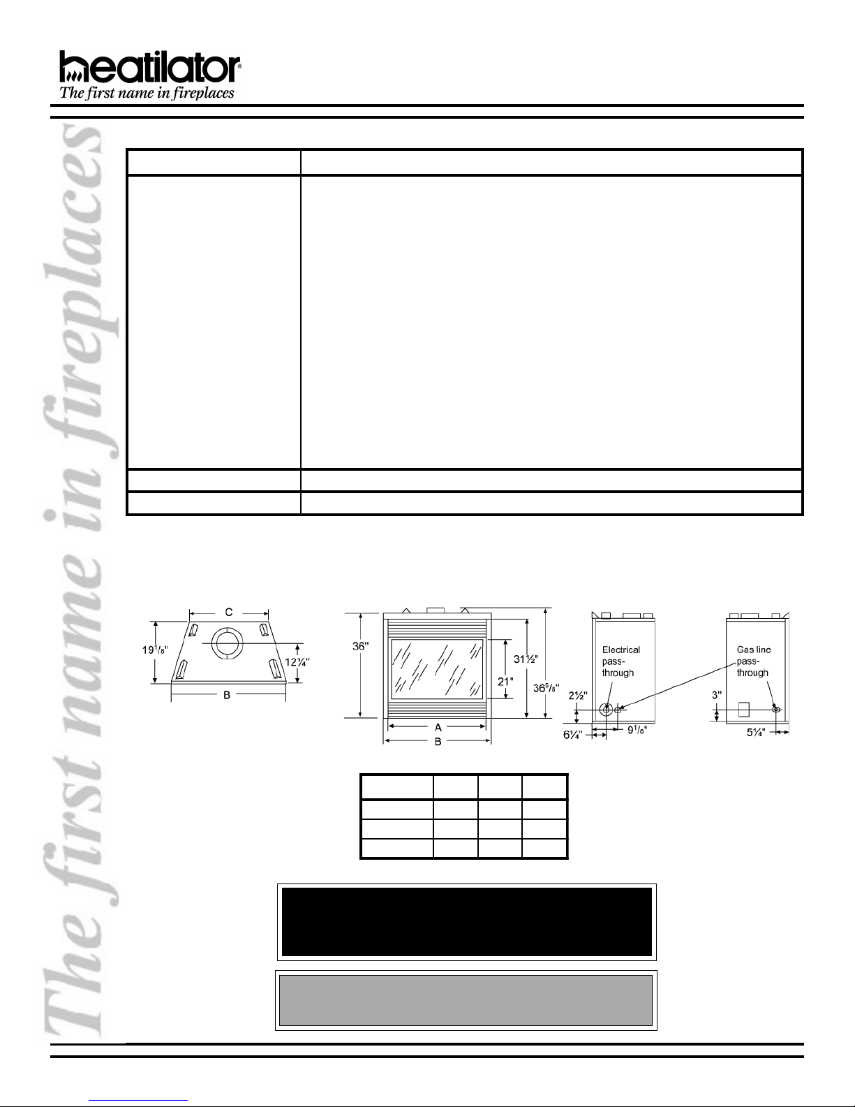
B. LOCATION AND CLEARANCES
Appliance Dimensions
LEDOMABC
7
03CBNG"0343
33CBNG"3373
63CBNG"6304
WARNING!
Due to high temperatures, the appliance should be located
out of traffic and away from furniture and draperies.
/8"85/8"
7
/8"115/8"
7
/8"415/8"
Do not expose appliance to the elements (such as rain, etc.)
28466 Rev H 4 01-02
CAUTION
NOVUS B-VENT INSTALLATION INSTRUCTIONS
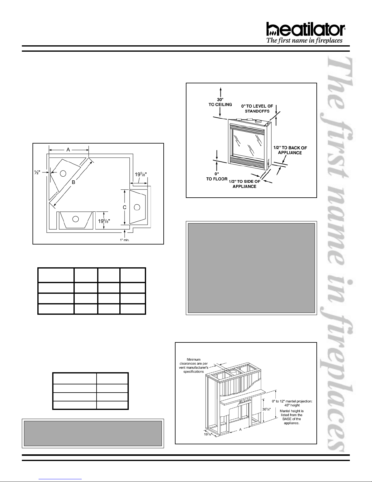
1. APPLIANCE LOCATIONS AND SPACE
REQUIREMENTS
Figure 1 illustrates a variety of ways the appliance
may be located in a room. The NOVUS Series may be
installed directly on the floor or raised on a hearth.
These appliances are certified for installation in a
bedroom, bed/sitting rooms or bathrooms in the U.S.
and Canada, provided that the bedroom or bathroom
has a volume of at least 540 cubic feet.
Common venting of this gas appliance with other gas
appliances is not allowed in multifamily dwellings.
Figure 1
Appliance Locations
LEDOMABC
03CBNG43
33CBNG63
63CBNG83
1
/4"84
1
/4"151/4"837/8"
3
/8"451/4"147/8"
1
2/
"537/8"
2. CLEARANCES
Figure 2 shows all clearances that must be
maintained around the appliance.
Figure 2
Appliance Clearances to Combustible Materials
We strongly recommend that you DO NOT install
B-Vent Gas Appliances in strong negative air
locations, such as a basement or a public facility.
Living rooms with cathedral ceilings could be
susceptible to a negative air situation, but such
installations can be overcome through raising
the termination, depending on specific
installations. This appliance uses room air for
normal operation and could have problems
establishing a positive draft in a negative air
location. In lieu, we recommend a direct vent
appliance.
Figure 3 shows a typical framing of this appliance using
combustible materials. All required clearances to
combustibles must be adhered to.
LEDOMA
7
03CBNG53
33CBNG83
63CBNG14
/8"
7
/8"
7
/8"
CAUTION
Wear gloves and safety glasses for protection.
01-02 5 28466 Rev H
C. FRAMING
Figure 3 - Framing
NOVUS B-VENT INSTALLATION INSTRUCTIONS
CAUTION
Provide adequate clearances around the air openings into the combustion chamber and adequate accessibility
clearances for servicing and proper operation.
D. SETTING THE APPLIANCE
1. POSITIONING THE APPLIANCE
This appliance may be placed on a smooth
combustible or noncombustible, continuous flat
surface. When the appliance is installed directly on
carpeting, tile or other combustible material other than
wood flooring, the appliance shall be installed on a
metal or wood panel extending the full width and depth
of the appliance. Slide the appliance into position and
level from side-to-side and front-to-back. Shim with
noncombustible materials as necessary.
Secure the appliance by bending out the nailing
flanges on each side of the appliance and nail to
framing. The nailing flanges have been positioned
5/8 inch back from the front of the appliance to allow
the addition of drywall.
WARNING!
To prevent contact with sagging or loose
insulation, the appliance must not be installed
against vapor barriers or exposed insulation.
Localized overheating could occur and a fire
E. VENTING
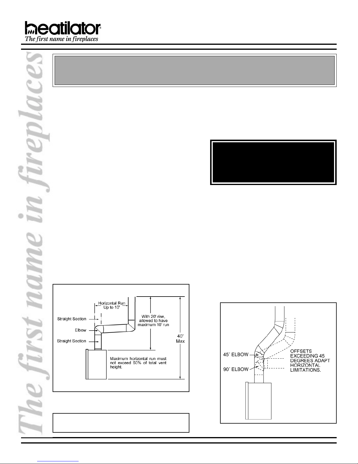
1. VENT HEIGHT
This appliance requires a 5 B-vent for operation.
Never downsize pipe. It must be terminated above
the roof line. Follow all B-vent requirements and
installation instructions, including minimum
clearances.
The minimum height of vent installation must be nine
feet from the top or twelve feet from the base of the
appliance. Horizontal run must never exceed 50% of
the height of the vent system as shown in Figure 4.
2. ATTACHING VENTING
a. Assembling Vent Sections. Attach straight vent
section to the top of appliance. Use only B-vent
sections.
b. Attaching the Vent to the Collar Shield. Three
tabs extend from the collar shield to the B-vent
section. Screw the tabs to the B-vent section using
self-tapping screws.
c. Using Elbows. Elbows exceeding 45° from the
vertical shall be considered horizontal and
therefore adapt horizontal run limitations. See
Figure 5.
Figure 4
Venting Off the Top of Appliance
Note: Vertical rise off the top of the firebox before elbow-
ing creates a less restrictive venting environment.
28466 Rev H 6 01-02
Figure 5 - Using Elbows
NOVUS B-VENT INSTALLATION INSTRUCTIONS
WARNING - RISK OF FIRE
Always maintain minimum clearances or greater
around the vent system. Do not pack air spaces with
insulation or other material. The flow of combustion
and ventilation air must not be obstructed.
WARNING!
The horizontal run of vent must have a 1/4 rise for
every 1 ft. of run towards the termination. Never allow
the vent to run downward. This could cause high
temperatures and may present a fire hazard.
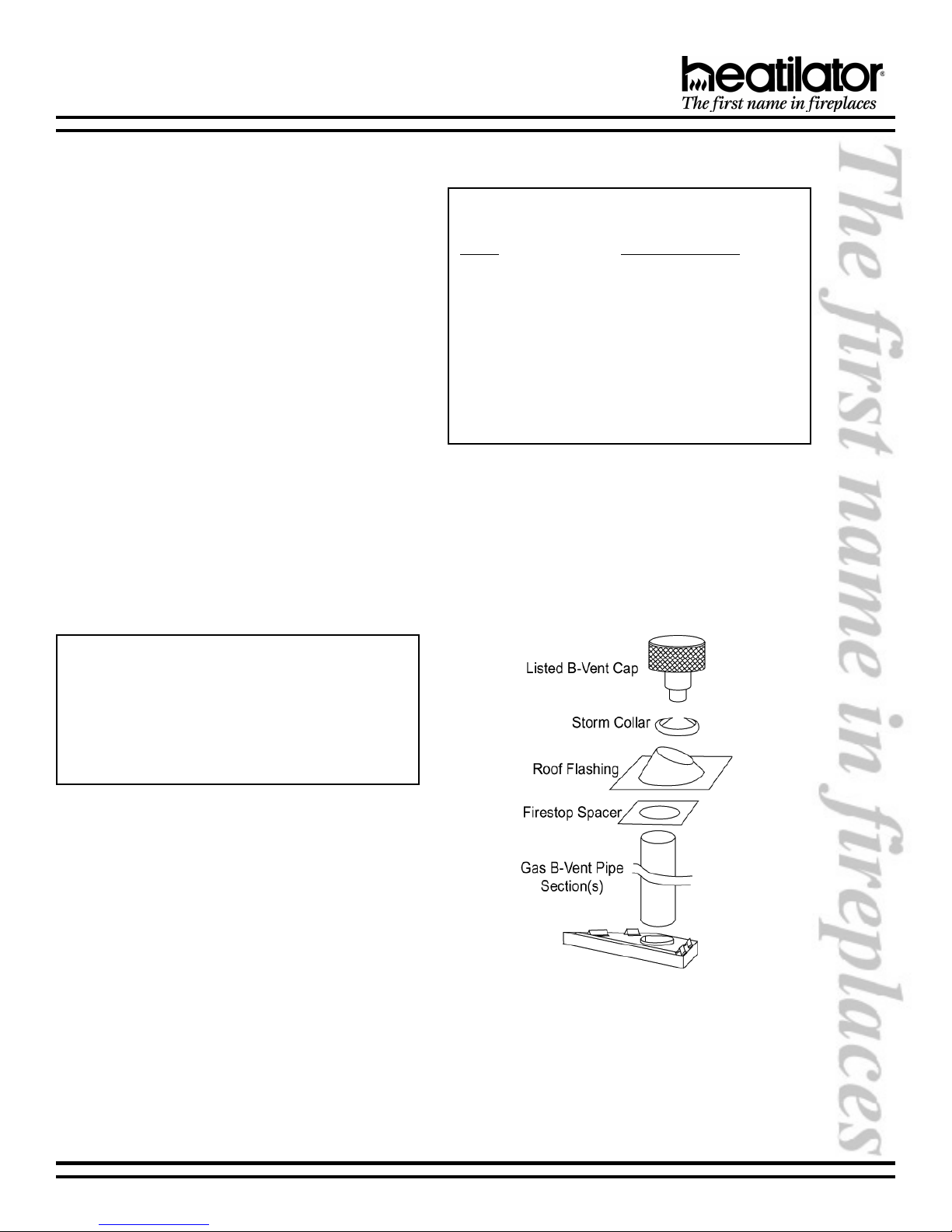
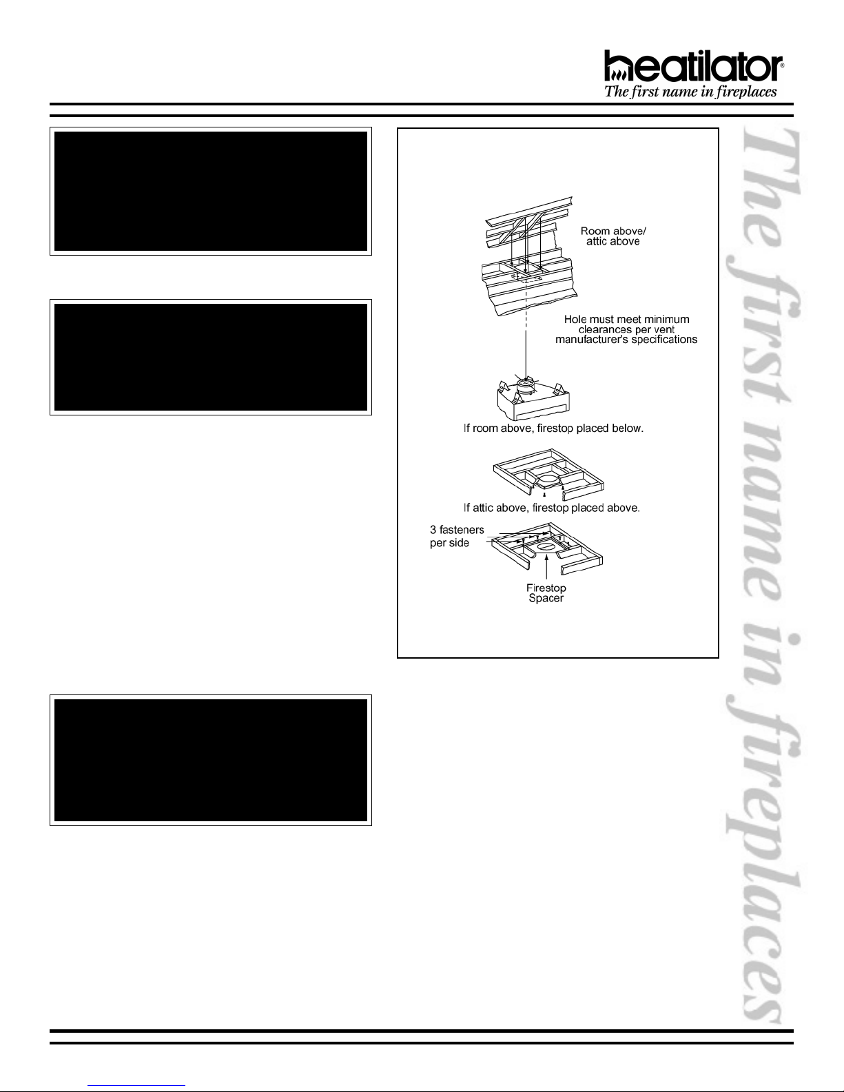
3. FIRESTOP SPACER/VENT
INSTALLATION
Frame an opening and install a firestop spacer
whenever the vent penetrates a ceiling floor area, as
shown in Figure 6. Frame the opening with the same
sized lumber as used in the ceiling/floor joist. Unless
the flue is offset, the hole should be directly above the
appliance. DO NOT pack insulation around the vent.
Assemble vent sections with three screws per joint.
WARNING!
When vent sections exceeding three feet in length
are installed between an offset/return, structural
support must be provided to reduce off-center
loading and prevent vent sections from separating
at the vent joints. Follow all B-vent manufacturer
guidelines.
Figure 6
Installing the Firestop Spacer
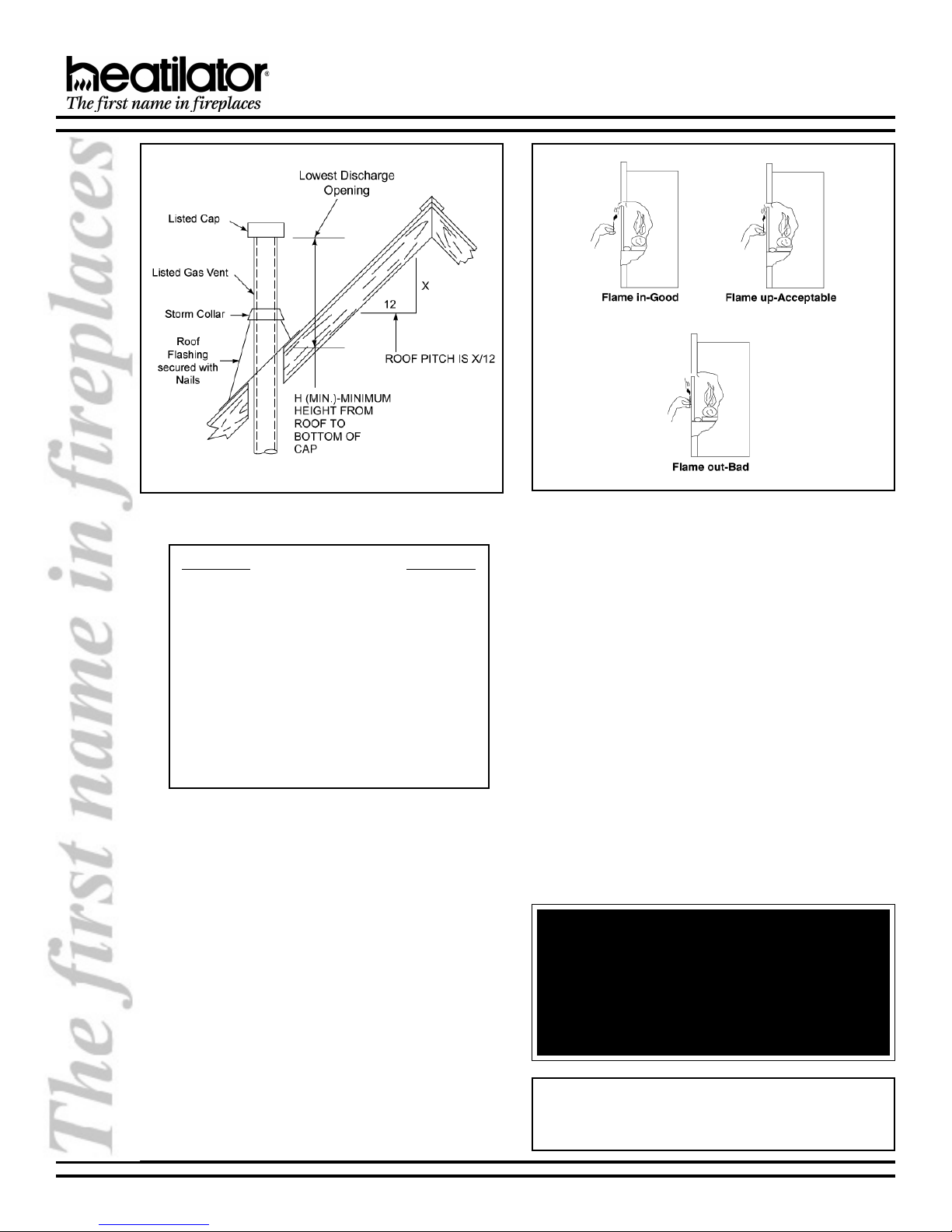
4. CHASE/TERMINATION INSTALLATION
Figure 7 and Table 1 specify minimum vent heights
for various pitched roofs. Vent sections may have to
be cut to a certain length.
These vent heights are necessary for safety and do
not ensure draft-free operation. Trees, buildings,
adjoining roof lines, adverse conditions, etc., may
create a need for a taller vent should down drafting
occur.
01-02 7 28466 Rev H
NOVUS B-VENT INSTALLATION INSTRUCTIONS
Figure 7
Vent Height for Vertical Termination
Roof Pitch H (Min.) Ft.
Flat to 6/12 ................................................ 1.0
6/12 to 7/12 ............................................... 1.25
Over 7/12 to 8/12 ...................................... 1.5
Over 8/12 to 9/12 ...................................... 2.0
Over 9/12 to 10/12 .................................... 2.5
Over 10/12 to 11/12 .................................. 3.25
Over 11/12 to 12/12 .................................. 4.0
Over 12/12 to 14/12 .................................. 5.0
Over 14/12 to 16/12 .................................. 6.0
Over 16/12 to 18/12 .................................. 7.0
Over 18/12 to 20/12 .................................. 7.5
Over 20/12 to 21/12 .................................. 8.0
Table 1
Vent Height
5. CHECK VENTING SYSTEM
Check the venting system to assure proper operation.
This can be done with a match while the appliance is
operating.
Hold a lighted match at the bottom edge of the draft
hood opening. If the flames and smoke remain upright,
ventilation is acceptable. If the flames and smoke are
drawn into the draft hood, this means ventilation is
good. If the flames and smoke are forced away from
the draft hood, this may indicate a ventilation blockage
or down draft resulting in gas spillage into the home.
If this occurs, turn off the appliance and do not burn it
until it has been inspected by a qualified service
person. See Figure8.
Figure 8
Testing Ventilation
6. INSTALLING AN OUTSIDE AIR KIT
(STRONGLY RECOMMENDED)
An AK14 Outside Air Kit should be purchased as a
feature with this appliance. An outside air kit helps to
decrease the amount of room air taken by utilizing
outside air for combustion. Figure 9 illustrates two of
many possible methods that can be used to supply
outside air to the appliance.
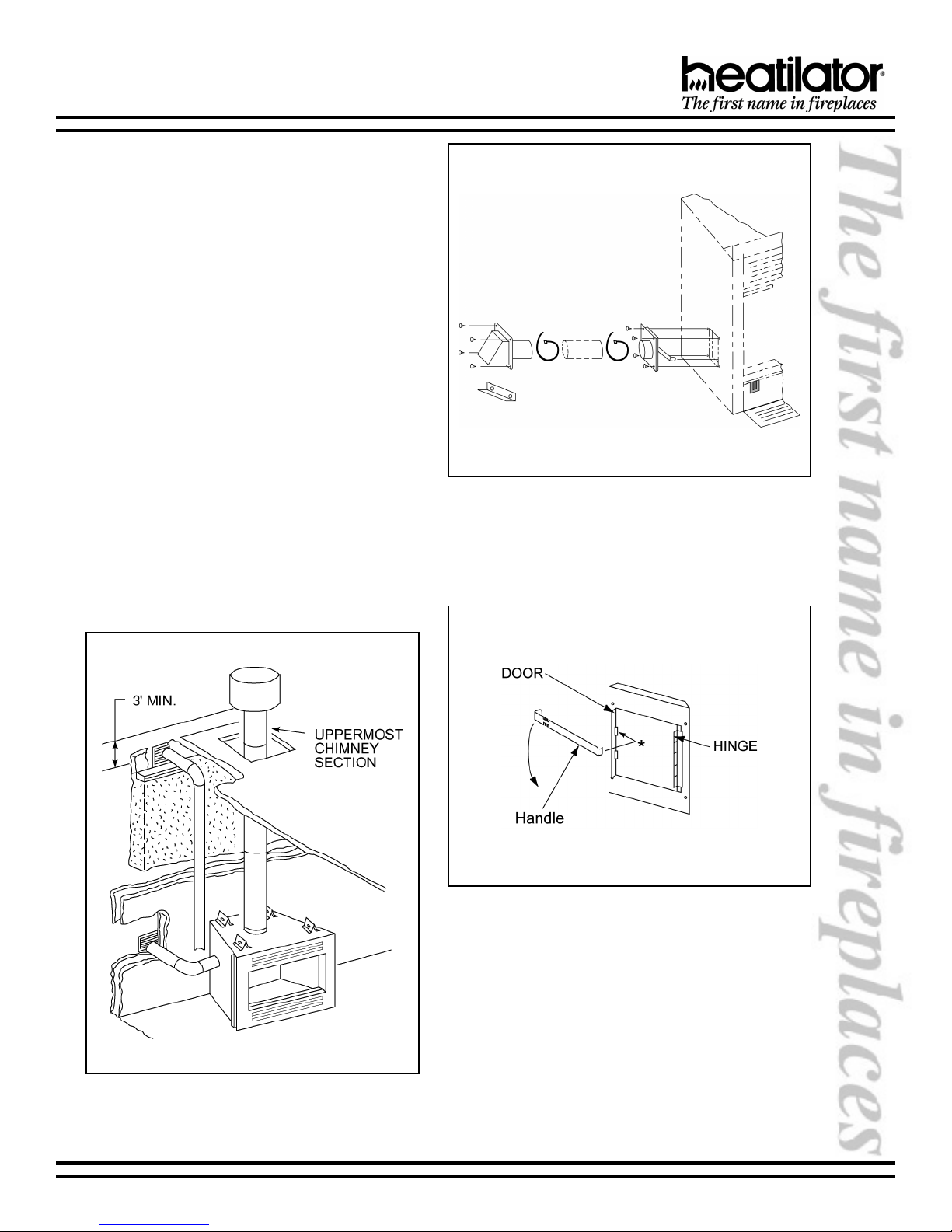
A maximum of 40 of air kit ducting is allowed. The air
kit must terminate at least three feet below the venting
termination and must terminate to the outside.
WARNING!
Exhaust products of gasoline engines are
hazardous. The outside air must not be taken from a
garage space, attic spaces, basements or above
the roofing where other heating appliances, fans or
chimneys exhaust or utilize air.
Note: The outside air kit can terminate at any level with
the exception that it must terminate at least one foot
below the chimney termination cap.
28466 Rev H 8 01-02
NOVUS B-VENT INSTALLATION INSTRUCTIONS
a. The air kit can only be installed on the left side of
the appliance. See Figures 10 and 11 for correct
orientation of the door assembly and handle. The
hinge will be toward the back of the appliance.
b. Remove the cover plate or knockout from the side
of the appliance and discard.
c. Partly open the air kit door. The hinge on the door
assembly should be located toward the back of
the appliance. If the hinge is not positioned in
this manner, the door will not function correctly.
d. Attach the door assembly to the appliance using
the screws provided.
e. Bend down the left tab on the lower left glass
retainer. Insert the narrow end of the handle
through the tab and into the upper slot on the air
kit door.
f. Check operation by pulling the handle out to open,
and pushing it in to close.
g. Mark and cut a hole in the building side for air
entry. This hole should allow some framing (two
sides) so the inlet tube assembly may be
fastened properly.
h. Assemble the flexible duct (not supplied) between
the door assembly and the inlet tube assembly.
Secure it in position with the supplied wire ties.
Figure 10 - Air Kit Installation
Figure 9 - Outside Air Locations
01-02 9 28466 Rev H
Figure 11 - Air Kit Door Assembly & Handle
 Loading...