

Page 1

INSTALLATION & OPERATING
INSTRUCTIONS
GFK-21 FAN KIT
If you need clarification of any of the instructions contained here contact your dealer or the Heatilator Technical Services Department
at 1-800-927-6841.
The GFK-21 Fan Kit has been designed to circulate room air through the appliance to enhance heat output. The fan kit operates on
120VAC, 60 Hz power. This is available through a receptacle in the factory installed junction box. The junction box is located in the
controls compartment of the appliance.
A variable speed control is provided with the fan kit to provide quiet forced air flow at the desired speeds. A temperature sensor switch,
which automatically turns the fan on and off, is also provided with this kit.
Check Contents of Shipping Carton
Compare contents of carton in Table 1 with the actual parts received. If any parts are missing or damaged, contact your dealer
before starting installation. Do not install a damaged fan kit.
Installation Precautions
The GFK-21 Fan Kit is tested and safe when installed in accordance with this installation manual. It is your responsibility to read
all instructions before starting installation and to follow these instructions carefully during installation to assure maximum
benefit from, and safe operation of, the fan.
This fan is carefully engineered and must be installed only as specified. If you modify it or any of its components, you may cause
a fire hazard and will void the warranty. In addition, such action may void the coverage provided by the owner’s home insurance.
CAUTION:
All wiring should be done by a qualified electrician and shall
be in compliance with local codes and with the National
Electric Code ANSI/NFPA NO. 70-current (in the United
States), or with the current CSA C22.1 Canadian Electric
Code (in Canada).
WARNING!
Do not connect 110-120VAC wiring to the gas control valve
of this fireplace.
Note: An arrow () found in the text signifies change in content.
05/04 4031-292 Rev D 1
Description Qty.
Fan Assemb ly 1
Cord Clip 2
Screws 8
Foam Tape 1
Speed Control 1
Temperature Sensor Switch 1
Control Nut 1
Control Knob 1
Magnetic Tape 2
Fan Bracket 1
Hook Tape 1
Loop Tape 1
Table 1 - Contents of Carton
Page 2

GFK-21 FAN KIT INSTALLATION INSTRUCTIONS
1. Install the Fan Bracket & Shield
a. Place the fan bracket around the fan. See Figure 1.
Figure 1 - Fan Bracket-No screws
b. Install the two screws through the fan bracket
into the back of the fan housing to hold the bracket
in place. See Figure 2.
d. If no fan shield is needed, install screws to hold
the front of the fan bracket in place. See Figure 4.
e. Attach the foam tape (Figure 5) and magnets
(Figure 6) to the fan. Cut one magnet strip in half
and use the remaining strip as needed.
Figure 4 - Fan Bracket
Figure 2 - Insert Screws
Figure 5 - Foam Tape
c. If the fan is being installed in a B-vent appliance,
the fan shield supplied with the appliance will
also need to be attached. See Figure 3.
Figure 3 - Fan Shield
2 4031-292 Rev D 05/04
Figure 6 - Magnets
Page 3
GFK-21 FAN KIT INSTALLATION INSTRUCTIONS
2. Remove Valve Assembly
On a Novus 30 in. appliance (GNDC30 or GNBC30
only) the valve assembly must be raised slightly to
allow the fan to be moved past it to the back of the
appliance.
3. Install the Fan
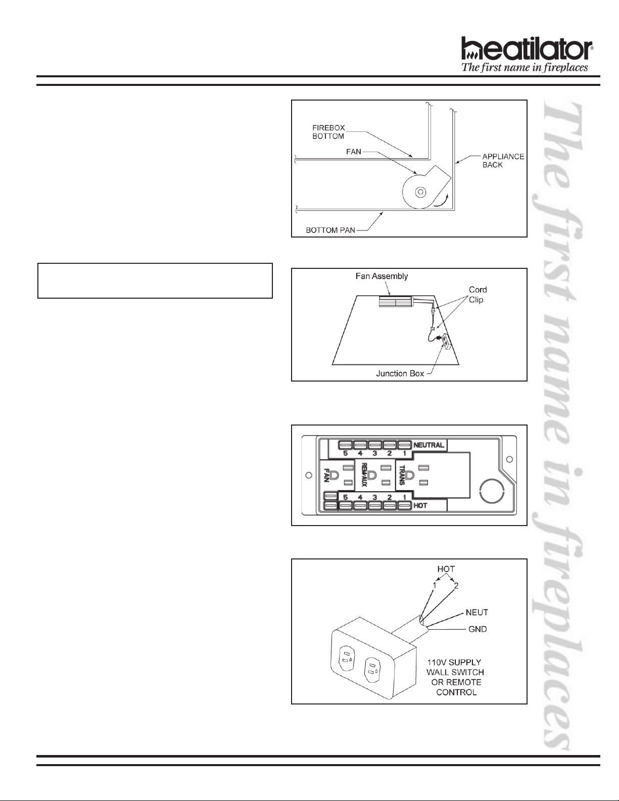
Position the fan all the way to the rear and center in
the appliance. Press the fan (magnets to the bottom)
to the back of the appliance. See Figure 7. Plug the
fan cord into the fan receptacle on the junction box.
See Figure 8.
Note: Refer to Figures 9 and 10 to determine which
junction box you have.
4. Install the Speed Control
(Junction Box A only)
Attach the speed control to the bottom pan using the
velcro tape provided. Attach the knob to the stem on
the speed control.
Figure 7 - Rotate Fan
Figure 8 - Position the Fan
Figure 9 - Junction Box A
Figure 10 - Junction Box B
05/04 4031-292 Rev D 3
Page 4
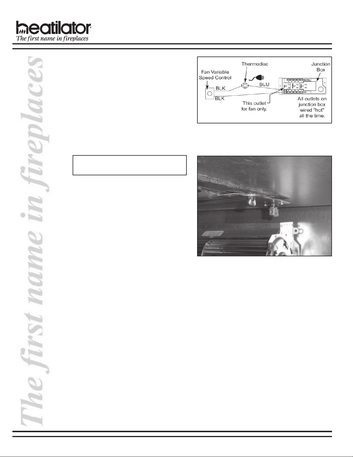
5. Install the Sensor Switch Bracket
(Junction Box A only)
a. Remove the wing nut on the right rear side of the
seal plate.
b. Install the middle hole of the bracket on the same
stud the wing nut was removed from. Replace
the wing nut and tighten the seal plate. See
Figure 13.
c. Connect the variable speed control and the
temperature sensor switch to the short lead
wires of the junction box by plugging in the male
to female connectors. See Figure 12.
Note: If using junction box B, discard the
temperature sensor switch and speed control.
d. Turn the 110-120VAC service on at the circuit
breaker and turn the speed control switch to the
“ON” position.
GFK-21 FAN KIT INSTALLATION INSTRUCTIONS
Figure 12 - Fan Wiring Diagram
Figure 11 - Install Sensor Switch Bracket
4 4031-292 Rev D 05/04
 Loading...