

Heatilator GGBR60, GGBR60IL, GGBR80, GGBR80L, GGBR80I Installation & Owner's Manual
...
WARNING!
Installation and service must be performed by a qualified installer, service agency or the gas supplier. Improper installation,
adjustment, alteration, service or maintenance can cause injury or property damage. Refer to this manual. For assistance or
additional information, consult a qualified installer, service agency or the gas supplier.
This manual must be used for installation of the
Geneva Series Gas Appliance and retained by the
homeowner for operation and maintenance
instructions.
CAUTION:
Do not expose the appliance to the
elements (such as rain, etc.).
Æ
INSTALLATION & OWNERS MANUAL
GENEVA SERIES B-VENT GAS APPLIANCE
MODELS: GGBR60, GGBR60L, GGBR60I, GGBR60IL
GGBR80, GGBR80L, GGBR80I, GGBR80IL
WARNING: If the information in this manual
is not followed exactly, a fire or explosion may
result causing property damage, personal injury or loss of life.
Do not store or use gasoline or other flammable
vapors and liquids in the vicinity of this or any other
appliance.
What to do if you smell gas
Do not try to light any appliance.
Do not touch any electrical switch; do not use
any phone in your building.
Immediately call your gas supplier from a
neighbors phone. Follow the gas suppliers
instructions.
If you cannot reach your gas supplier, call the
fire department.
Installation and service must be performed by a
qualified installer, service agency or the gas
supplier.
10/03 32912 Rev L 1

GENEVA SERIES B-VENT GAS APPLIANCE
TABLE OF CONTENTS
Design and Installation Considerations for B-Vents ...................................................................................................... 3
A. Appliance Specifications................................................................................................................................................ 4
B. Location and Clearances ............................................................................................................................................... 6
C. Framing .......................................................................................................................................................................... 7
D. Setting the Appliance ..................................................................................................................................................... 7
E. Venting ........................................................................................................................................................................... 8
F. Utilities ......................................................................................................................................................................... 11
G. Finishing ...................................................................................................................................................................... 14
H. Appliance Preparation ................................................................................................................................................. 14
I. Determining the Ignition ............................................................................................................................................... 16
J. Lighting Instructions ..................................................................................................................................................... 16
K. Seasonal Checklist ...................................................................................................................................................... 18
L. Start-up Issues ............................................................................................................................................................. 19
M. Maintenance Instructions ............................................................................................................................................. 20
N. Log Removal/Replacement ......................................................................................................................................... 22
O. Optional Components .................................................................................................................................................. 23
P. Replacement Parts ...................................................................................................................................................... 24
Index ............................................................................................................................................................................ 27
Limited Lifetime Warranty ............................................................................................................................................ 28
WARNING!
DO NOT use this appliance if any part has been under water. Immediately call a qualified service technician to
inspect the appliance and to replace any part of the control system and any gas control which has been under
water.
Safety Precautions
1. Please read these installation instructions completely before beginning installation procedures. Failure to follow them
could cause an appliance malfunction resulting in serious injury and/or property damage.
2. Always check your local building codes prior to installation. This installation must comply with all local, regional, state
and national codes and regulations.
3. Installation and repair should be done by a qualified service person. This appliance should also be inspected annually
by a qualified service person. More frequent inspections/cleaning may be required due to excessive lint from carpeting,
bedding materials, etc. It is imperative that the control compartment, burners and circulating air passageways of the
appliance be kept clean.
4. This is a vented decorative gas appliance. Do not burn wood or other material in this appliance.
5. NEVER leave children unattended when there is a fire burning in the appliance.
6. This appliance may only use the approved B-vent system shown in these installation instructions. Venting must not
be connected to chimney flue servicing a solid fuel burning appliance or a gas fuel burning appliance.
7. Use only the fuel gas specified on the rating label of this gas appliance.
8. The appliance area shall be kept clear and free from combustible materials, gasoline and other flammable vapors
and liquids.
9. While servicing this appliance, always shut off all electricity and gas to the appliance. This will prevent possible
electrical shock or burns. Also, make sure the appliance is completely cooled before servicing.
10. Do not use this appliance if any part has been under water. Immediately call a qualified service technician to inspect
the appliance and to replace any part of the control system and any gas control which has been under water.
11. Be sure to provide adequate clearances around the air openings into the combustion chamber and adequate
accessibility clearances for servicing and proper operation.
12. Provisions shall be made to provide adequate combustion and ventilation air. The flow of combustion and ventilation
air should not be obstructed.
2 32912 Rev L 10/03
GENEVA SERIES B-VENT GAS APPLIANCE
DESIGN AND INSTALLATION CONSIDERATION
When selecting a location for your B-Vent appliance, it is important to evaluate a number of considerations.
Modern construction techniques can create conditions that may not allow your vent to draft properly. This may
result in spillage from your B-Vent appliance, as well as cause other combustion appliances to operate incorrectly.
Tightly sealed construction is important for energy efficiency. Unfortunately, a great deal of effort has been
directed to tightening up sidewall construction, while considerably less attention has been paid to tightening
upper portions of the warm air envelope (insulated ceilings). This has increased the Stack Effect, a condition
that increases the negative pressure generated by the structure. This negative pressure will directly affect the
drafting performance of a B-Vent appliance vent. To minimize the negative pressure generated by stack effect,
make certain that all ductwork installed in the attic spaces is sealed airtight. Minimize the number of recessed
light fixtures installed in the insulated ceiling and use sealed recessed light fixtures. Finally, make certain the
whole house fans and attic access panels are tightly sealed. These are important design considerations that
must be observed during the design and construction stage of the home.
If you desire to put an appliance in your basement, we recommend that you consider a direct vent gas appliance.
Basements always have a significant negative air pressure that causes the B-Vent system to be more susceptible
to spillage and cold flue backdrafting. Since direct vent gas appliances are sealed, they are not affected by the
negative pressure that exists in basements.
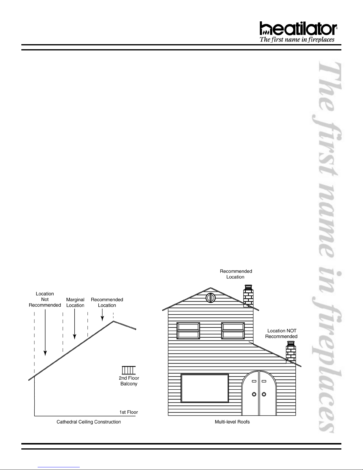
Finally, a B-Vent appliance performs best when the vent (roof termination) is located on the upper half of the roof,
especially when cathedral ceilings are present. Vents that are located on the lower half of the roof realize what is
known as lazy flue and will not draft as well as a vent that is located in the upper portion of the roof. The reason
for this is that the stack effect generated by the overall height of the living spaces inside the house will exceed the
draft generated by the vent system. If you desire to place an appliance in a location where the termination cap
would be located on the lower half of a roof; such as on an outside wall at the base of a cathedral ceiling, we
recommend that you consider using a direct vent gas appliance. This will ensure an appliance that operates
correctly.
These properties do not affect just your B-Vent appliance. They can cause any woodburning fireplace as well as
any conventionally vented (B-Vent) gas appliance to operate improperly. Careful planning at this stage of your
project will ensure satisfaction with the operation of your appliance once it is completed.
10/03 32912 Rev L 3
GENEVA SERIES B-VENT GAS APPLIANCE
A. APPLIANCE SPECIFICATIONS
U.S. and Canada Certification
The Geneva Series gas appliances have been tested in accordance with the standards ANSI Z21.50-1998, CGA 2.22M98, IR41, P4, and IR55 and have been listed by Underwriters Laboratories Inc. for installation and operation as described
in this manual. All components are UL, AGA, CGA or CSA safety certified.
Local Codes
This installation must conform with local codes. In the absence of local codes comply with the National Fuel Gas Code
ANSI Z223.1-latest edition in the U.S.A., and the CAN/CGA B149 Installation Codes in Canada.
If you need assistance during installation, please contact your local dealer or Heatilator Technical Services Department,
Hearth & Home Technologies Inc., 1915 W. Saunders Street, Mt. Pleasant, Iowa 52641, 1-800-927-6841.
Æ
HEATILATOR® is a registered trademark of Hearth & Home Technologies Inc., Division of HON INDUSTRIES.
WARNING!
Due to high temperatures, the appliance should be
located out of traffic and away from furniture and
draperies.
CAUTION:
Do not expose the appliance to the elements (such
as rain, etc.).
Note: Glass doors are not optional in the
Commonwealth of Massachusetts. They are required.
We strongly recommend that you DO NOT install
B-Vent Gas Appliances in strong negative air
locations, such as a basement or a public facility.
Living rooms with cathedral ceilings could be
susceptible to a negative air situation, but such
installations can be overcome through raising the
termination, depending on specific installations.
This appliance uses room air for normal operation
and could have problems establishing a positive
draft in a negative air location. In lieu, we
recommend a Direct Vent Gas Appliance.
4 32912 Rev L 10/03
GENEVA SERIES B-VENT GAS APPLIANCE
#golataCnoitpircseD
GGaveneGsaG
BtneV-B
RtnaidaR
06ecnailppA"63=06
LItoliPgnidnatS,saGlarutaN-xiffusoN
LI06RBGG rebmuNedoCedargpUhtiwrebmuNedoCredrOecnailppA
:elpmaxE
LI06RBGG tnettimretnI,saGenaporP,"63,tnaidaR,tneV-BaveneGsaG
erutalcnemoNAVENEG
ecnailppA"24=08
toliPgnidnatS,saGenaporP=L
noitingItoliPtnettimretnI,saGlarutaN=I
noitingItoliPtnettimretnI,saGenaporP=LI
ecnailppAnoitingItoliP
WARNING!
This appliance is tested and listed for use only with the optional accessories listed in these instructions. Use
of optional accessories not specifically tested for this appliance could void the appliance warranty and/or
result in a safety hazard.
Typical Installation Components
Note: Minimum and maximum clearances must be main-
tained at all times. Illustrations throughout these instructions reflect typical installations and are for design purposes only. Actual installation may vary slightly due to
individual design preferences.
The illustrations and diagrams used throughout these
installation instructions are not drawn to scale.
Tools and building supplies normally required for
installation:
Saw Wall-finishing materials
Pliers Framing material
Hammer Surround
Phillips screwdriver Caulking material
Tape measure Safety gloves
Plumb line Electric drill/bits
Level Framing Square
10/03 32912 Rev L 5
GENEVA SERIES B-VENT GAS APPLIANCE
B. LOCATION AND CLEARANCES
0RGHO $ % &
6HULHV
6HULHV
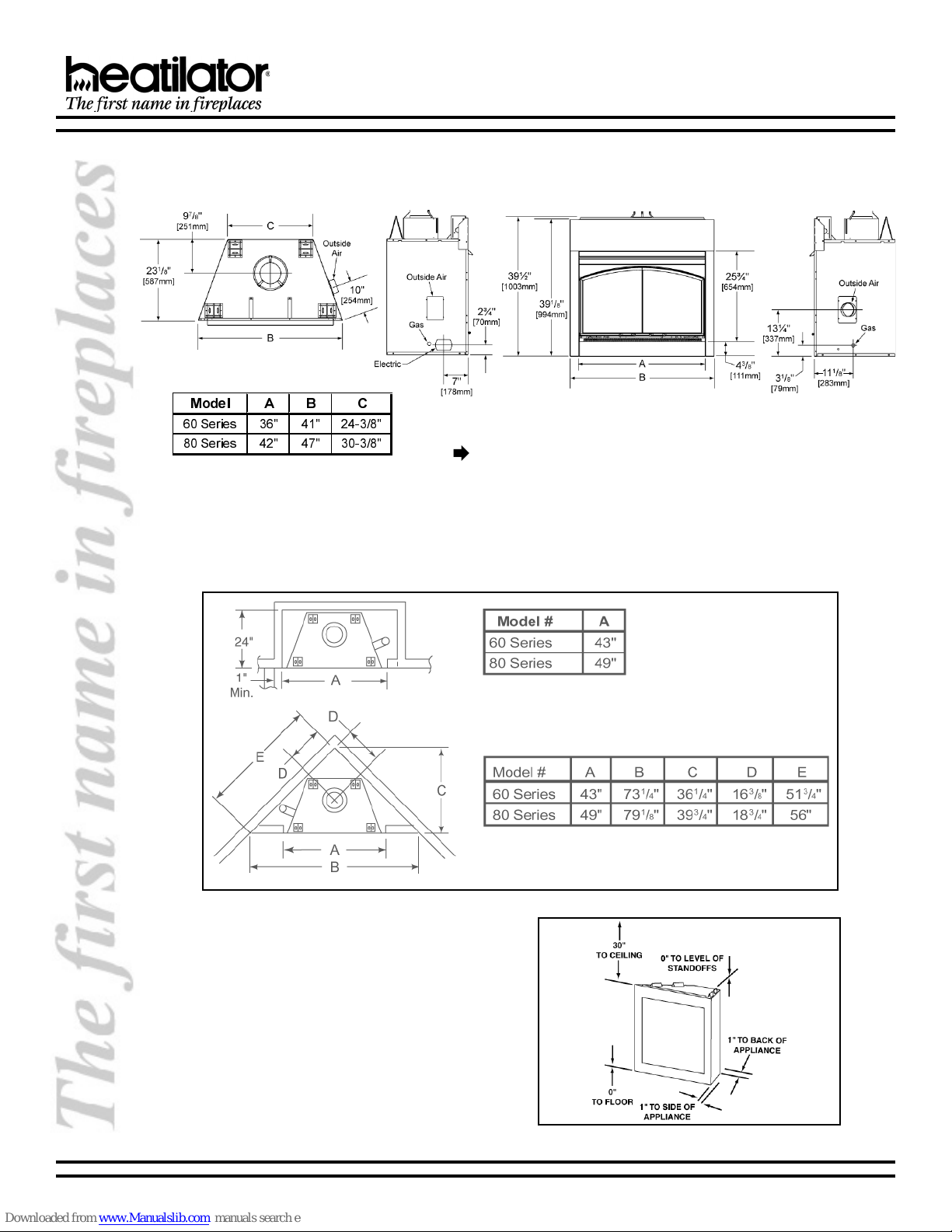
1. Appliance Locations and Space Requirements
Figure 1 illustrates a variety of ways the appliance may be located in a room. The Geneva Series gas appliances may
be installed directly on the floor or raised on a hearth. These appliances are certified for installation in a bedroom or
bed/sitting room in the U.S. and Canada, provided that the bedroom or bathroom has a volume of at least 1700 cubic
feet for the GGBR60 Series or 1800 cubic feet for the GGBR80 Series.
Dimensions
Æ
2. Clearances
Figure 2 shows all clearances that must be maintained
around the appliance.
6 32912 Rev L 10/03
Figure 1 - Appliance Locations
Figure 2 - Appliance Clearances to Combustible Materials
GENEVA SERIES B-VENT GAS APPLIANCE
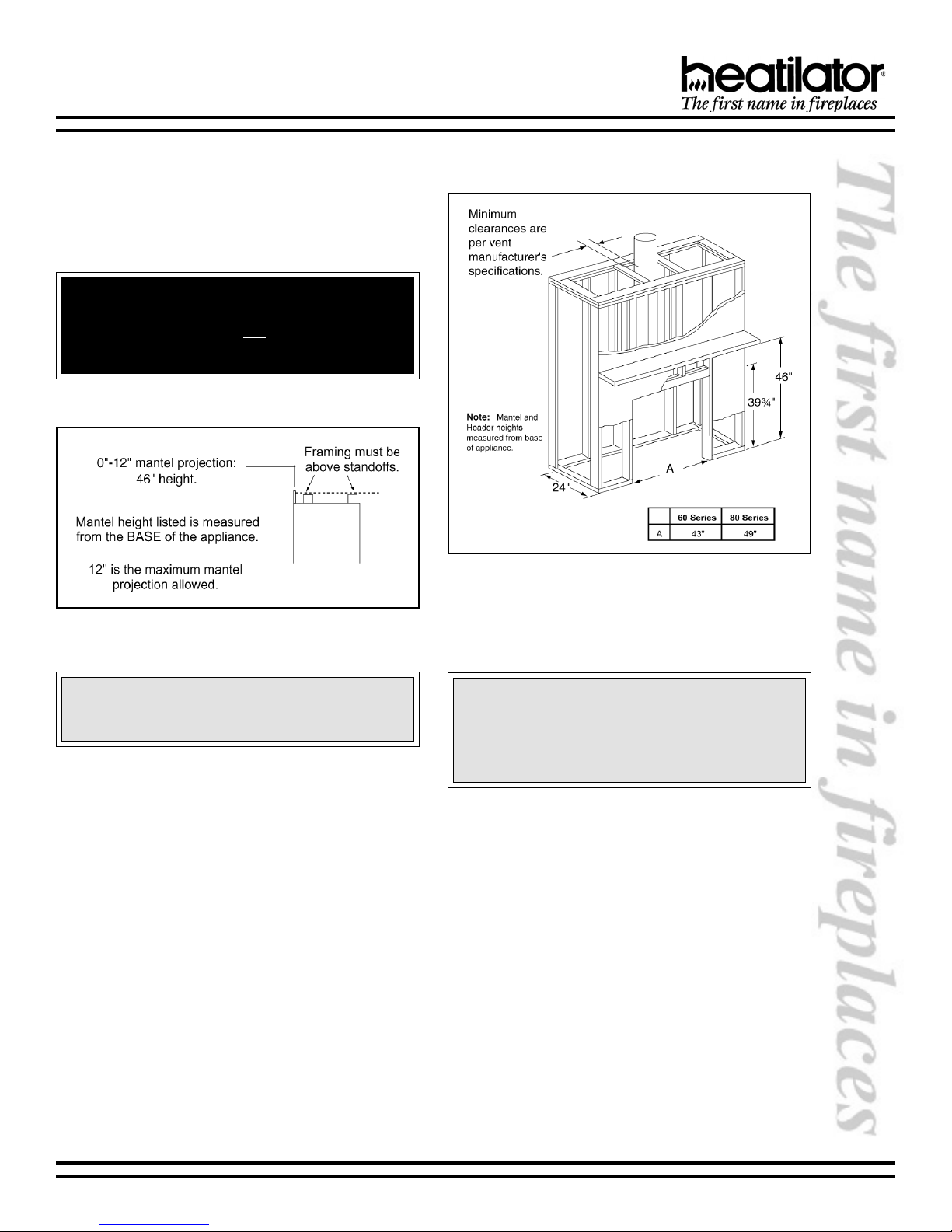
C. FRAMING
Figure 3 shows typical framing of this appliance using
combustible materials. Figures 3 and 4 show the minimum
mantel height. All required clearances to combustibles must
be adhered to.
WARNING!
To prevent contact with sagging or loose insulation, the appliance must
vapor barriers or exposed insulation.
GGBR60/80 MINIMUM MANTEL HEIGHT
not be installed against
Figure 3 - Framing
Figure 4
Mantel Heights
CAUTION:
Wear gloves and safety glasses for protection.
Provide adequate clearances around the air
openings into the combustion chamber and
adequate accessibility clearances for servicing and
proper operation.
CAUTION:
D. SETTING THE APPLIANCE
This appliance may be placed on a smooth combustible or noncombustible continuous, flat surface. When the appliance
is installed directly on carpeting, tile, or a combustible material other than wood flooring, the appliance shall be installed
on a metal or wood panel extending the full width and depth of the appliance. Slide the appliance into position and level
from side-to-side and front-to-back. Shim with noncombustible material as necessary.
Secure the appliance by bending out the nailing flanges on each side of the appliance and nail to framing. The nailing
flanges have been positioned 5/8 back from the front of the appliance to allow the addition of drywall.
10/03 32912 Rev L 7
GENEVA SERIES B-VENT GAS APPLIANCE
E. VENTING
Note: This appliance requires a 6 B-Vent for operation. NEVER DOWNSIZE PIPE.
WARNING!
This appliance may only use an approved B-Vent chimney system. It must not be connected to a chimney flue
servicing a separate solid fuel or gas fuel burning appliance.
1. Clearances
Vent clearances are per vent manufacturers specifications.
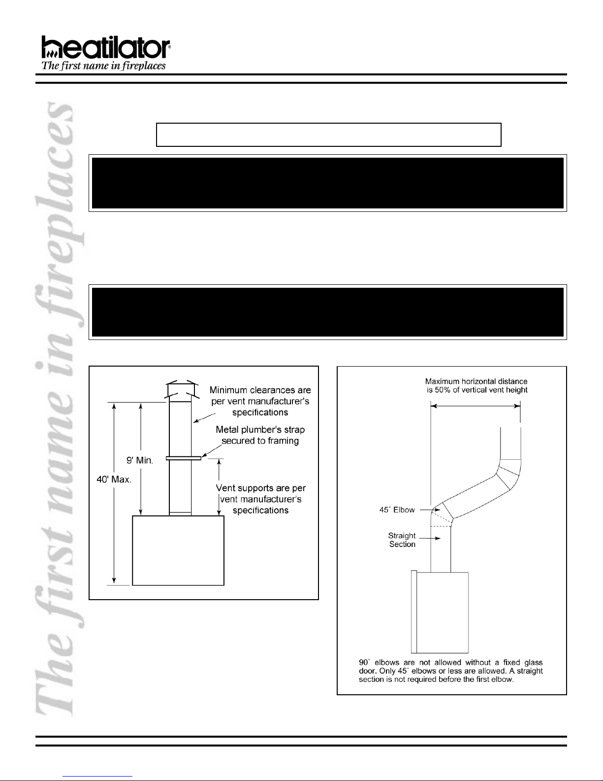
2. Vent Lengths
Various venting configurations are shown in Figures 5-7 from which maximum vent runs can be determined.
WARNING - RISK OF FIRE!
Always maintain minimum clearances or greater around the vent system. Do not pack air spaces with insulation or other material.
Figure 5
Top Vent - No Elbows
8 32912 Rev L 10/03
Figure 6
Venting off the Top of the Appliance
GENEVA SERIES B-VENT GAS APPLIANCE
3. 90° Elbows
A maximum of four 90° elbows may be used on this
appliance when used in conjunction with the fixed glass
doors shown below. See Figure7.
Acceptable fixed glass doors are:
DF361B/S
DF421B/S
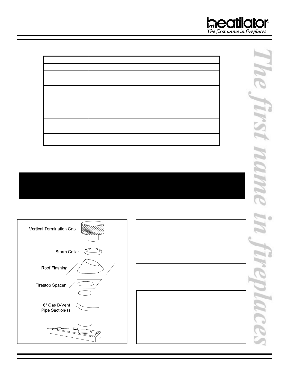
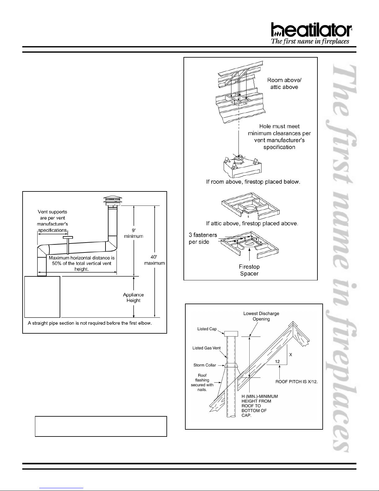
4. Firestop Spacer/Vent Installation
Frame an opening and install a firestop spacer
whenever the vent penetrates a ceiling/floor area, as
shown in Figure 8. Frame the opening with the same
sized lumber as used in the ceiling/floor joists. Unless
the flue is offset, the hole should be directly above the
appliance. DO NOT pack insulation around the vent.
Assemble vent sections as per manufacturers
specifications.
Figure 7 - 90° Elbows
5. Chase/Termination Installation
Figure 9 and Table 1 specify minimum vent heights for
various pitched roofs. Vent sections may have to be
cut to a certain length.
These vent heights are necessary for safety and do
not ensure draft-free operation. Trees, buildings,
adjoining roof lines, adverse conditions, etc. may create
a need for a taller vent should down drafting occur.
Note: To ensure proper operation, verify all venting
and the termination are unobstructed.
Figure 8 - Installing the Firestop Spacer
Figure 9 - Vent Height for Vertical Termination
10/03 32912 Rev L 9
 Loading...