

Heatilator GDST4336I, GDCR4136I, GDCL4136I, GDFL4136I Owner's Manual
Para obtener un ejemplar en Español de este
Manual del propietario, visite www.heatnglo.com.
Models:
GDST4336I
GDFL4136I
GDCR4136I
GDCL4136I
Pour demander un exemplaire en français de ce Manuel
du propriétaire, visitez www.heatnglo.com.
Owner’s Manual
Installation and Operation
NOTICE
DO NOT DISCARD THIS MANUAL
• Important operating
and maintenance
instructions included.
WARNING:
FIRE OR EXPLOSION HAZARD
Failure to follow safety warnings exactly
could result in serious injury, death, or
property damage.
• DO NOT store or use gasoline or other fl am-
mable vapors and liquids in the vicinity of this
or any other appliance.
• What to do if you smell gas
- DO NOT try to light any appliance.
- DO NOT touch any electrical switch. DO
NOT use any phone in your building.
- Leave the building immediately.
• Read, understand and follow
these instructions for safe
installation and operation.
DO NOT
DISCARD
• Leave this manual with
party responsible for use
and operation.
DANGER
HOT GLASS WILL
CAUSE BURNS.
DO NOT TOUCH GLASS
UNTIL COOLED.
NEVER ALLOW CHILDREN
TO TOUCH GLASS.
A barrier designed to reduce the risk of
burns from the hot viewing glass is provided
with this appliance and shall be installed for
the protection of children and other at-risk
individuals.
- Immediately call your gas supplier from
a neighbor’s phone. Follow the gas supplier’s instructions.
- If you cannot reach your gas supplier, call
the fi re department.
• Installation and service must be performed
by a qualifi ed installer, service agency, or the
gas supplier.
In the Commonwealth of Massachusetts installation must be
performed by a licensed plumber or gas fi tter.
See Table of Contents for location of additional Commonwealth
of Massachusetts requirements.
Heatilator • GDST4336I, GDFL4136I, GDCR4136I, GDCL4136I • 2129-900 Rev. W • 12/15
This appliance may be installed as an OEM
installation in manufactured home (USA
only) or mobile home and must be installed
in accordance with the manufacturer’s
instructions and the Manufactured Home
Construction and Safety Standard, Title 24
CFR, Part 3280 in the United States, or the
Standard for Installation in Mobile Homes,
CAN/CSA Z240 MH Series, in Canada.
This appliance is only for use with the type(s)
of gas indicated on the rating plate. This
appliance is not convertible for use with other
gases, unless a certifi ed kit is used.
1

Read this manual before installing or operating this appliance.
Please retain this owner’s manual for future reference.
A. Congratulations
Congratulations on selecting a Heatilator gas fi replace, an
elegant and clean alternative to wood burning fi replaces.
The Heatilator gas fi replace you have selected is designed
to provide the utmost in safety, reliability, and effi ciency.
This owner’s manual should be retained for future
reference. We suggest that you keep it with your other
important documents and product manuals.
The information contained in this owner’s manual, unless
noted otherwise, applies to all models and gas control
systems.
As the owner of a new fi replace, you’ll want to read and
carefully follow all of the instructions contained in this
owner’s manual. Pay special attention to all cautions and
warnings.
Homeowner Reference Information
Your new Heatilator gas fi replace will give you years of
durable use and trouble-free enjoyment. Welcome to the
Heatilator family of fi replace products!
We recommend that you record the following pertinent
information about your fi replace.
Model Name: ___________________________________________ Date purchased/installed: __________________
Serial Number: __________________________________________ Location on fi replace: _____________________
Dealership purchased from: _______________________________ Dealer Phone: __________________________
Notes: _______________________________________________________________________________________
_____________________________________________________________________________________________
Listing Label Information/Location
The model information regarding your specifi c fi replace can be found on
the rating plate usually located in the control area of the fi replace.
Type of Gas
Heat & Glo, a brand of Hearth & Home Technologies
7571 215th Street West, Lakeville, MN 55044
Not Not for for use use with with solid solid fuel.fuel.
((Ne Ne doit doit pas pas entre entre utilise utilise avec avec un un combustible combustible solide).solide).
Type Type o f of Gas Gas (Sorte (Sorte De De Gaz)Gaz)::
NNAATURALTURAL GASGAS
This This appliance appliance must must b e be installed installed in in accordance accordance with with local local codes, codes, if if any; any; if if not, not, follow follow ANSI ANSI Z223.1Z223.1
in in the the USA USA or or CAN/CGA CAN/CGA B149 B149 installation installation codes. codes. (Installer (Installer l’appareil l’appareil selon selon les les codes codes ou ou reglementsreglements
locaux locaux ou, ou, en en l’absence l’absence de de tels tels reglements, reglements, selon selon les les codes codes d’installation d’installation CAN/CGA-B149.)CAN/CGA-B149.)
ANSI ANSI Z21XX-XXXX Z21XX-XXXX · · CSA CSA 2.XX-MXX 2.XX-MXX
Gas and Electric
Information
Minimum Minimum Permissible Permissible Gas Gas Supply Supply for for Purposes Purposes of of Input Input Adjustment.Adjustment.
Approved Approved Minimum Minimum (De (De Gaz) Gaz) AcceptableAcceptable 0.00.0 in in w.c.w.c. (Po. (Po. Col. Col. d’eau)d’eau)
Maximum Maximum Pressure Pressure (Pression)(Pression) 0.00.0 in in w.c.w.c. (Po. (Po. Col. Col. d’eau)d’eau)
Maximum Maximum Manifold Manifold Pressure Pressure (Pression)(Pression) 0.00.0 in in w.c.w.c. (Po. (Po. Col. Col. d’eau)d’eau)
Minimum Minimum Manifold Manifold Pressure Pressure (Pression)(Pression) 0.00.0 in in w.c.w.c . (Po. (Po. Col. Col. d’eau)d’eau)
To ta l Total Electrical Electrical Requirements: Requirements: 000Vac, 000Vac, 00Hz., 00Hz., less less than than 00 00 AmperesAmperes
MADE MADE IN IN USAUSA
Model Number
ALTITUDE:ALTITUDE: 0-0000 0-0000 FT.FT. 0000-0000FT.0000-0000FT.
MAX. MAX. INPUT INPUT BTUH:BTUH: 00,00000,000 00,00000,000
MIN. MIN. INPUT INPUT BTUH:BTUH: 00,00000,000 00,00000,000
ORIFICE ORIFICE SIZE:S IZE: #XXXXX#XXXXX #XXXXX#XXXXX
Heatilator • GDST4336I, GDFL4136I, GDCR4136I, GDCL4136I • 2129-900 Rev. W • 12/152
IN IN CANADACANADA
Model:Model:
(Modele):(Modele):
SerialSerial
(Serie):(Serie):
XXXXXXXXXXXXXXXX
XXXXXXXXXXXXXXXX
Serial Number

Safety Alert Key:
• DANGER! Indicates a hazardous situation which, if not avoided will result in death or serious injury.
• WARNING! Indicates a hazardous situation which, if not avoided could result in death or serious injury.
• CAUTION! Indicates a hazardous situation which, if not avoided, could result in minor or moderate injury.
• NOTICE: Used to address practices not related to personal injury.
Table of Contents
A. Congratulations . . . . . . . . . . . . . . . . . . . . . . . . . . . . . . . . . 2
B. Limited Lifetime Warranty . . . . . . . . . . . . . . . . . . . . . . . . . . 5
1 Listing and Code Approvals
A. Appliance Certifi cation . . . . . . . . . . . . . . . . . . . . . . . . . . . . 7
B. Tempered Glass Specifi cations . . . . . . . . . . . . . . . . . . . . . 7
C. BTU Specifi cations . . . . . . . . . . . . . . . . . . . . . . . . . . . . . . . 7
D. High Altitude Installations . . . . . . . . . . . . . . . . . . . . . . . . . . 7
E. Non-Combustible Materials Specifi cation. . . . . . . . . . . . . . 7
F. Combustible Materials Specifi cation . . . . . . . . . . . . . . . . . 7
G. Electrical Codes . . . . . . . . . . . . . . . . . . . . . . . . . . . . . . . . . 7
H. Requirements for the Commonwealth of Massachusetts . . 8
User Guide
2 Operating Instructions
A. Gas Fireplace Safety . . . . . . . . . . . . . . . . . . . . . . . . . . . . . 9
B. Your Fireplace . . . . . . . . . . . . . . . . . . . . . . . . . . . . . . . . . . 9
C. Fan Kit (optional) . . . . . . . . . . . . . . . . . . . . . . . . . . . . . . . 10
D. Clear Space . . . . . . . . . . . . . . . . . . . . . . . . . . . . . . . . . . . 10
E. Decorative Doors and Fronts . . . . . . . . . . . . . . . . . . . . . . 10
F. Fixed Glass Assembly . . . . . . . . . . . . . . . . . . . . . . . . . . . 10
G. Remote Controls, Wall Controls and Wall Switches . . . . . 10
H. Before Lighting Fireplace . . . . . . . . . . . . . . . . . . . . . . . . . 10
I. Lighting Instructions (IPI) . . . . . . . . . . . . . . . . . . . . . . . . . 11
J. After Fireplace is Lit . . . . . . . . . . . . . . . . . . . . . . . . . . . . . 12
K. Frequently Asked Questions . . . . . . . . . . . . . . . . . . . . . . 12
3 Maintenance and Service
A. Maintenance Tasks-Homeowner . . . . . . . . . . . . . . . . . . . 13
B. Maintenance Tasks-Qualifi ed Service Technician . . . . . . 14
Installer Guide
4 Getting Started
A. Typical Appliance System. . . . . . . . . . . . . . . . . . . . . . . . . 15
B. Design and Installation Considerations . . . . . . . . . . . . . . 16
C. Tools and Supplies Needed . . . . . . . . . . . . . . . . . . . . . . . 16
D. Inspect Appliance and Components . . . . . . . . . . . . . . . . . 17
5 Framing and Clearances
A. Selecting Appliance Location . . . . . . . . . . . . . . . . . . . . . . 18
B. Constructing the Appliance Chase . . . . . . . . . . . . . . . . . . 19
C. Clearances . . . . . . . . . . . . . . . . . . . . . . . . . . . . . . . . . . . . 19
D. Mantel and Wall Projections . . . . . . . . . . . . . . . . . . . . . . . 21
6 Termination Locations
A. Vent Termination Minimum Clearances . . . . . . . . . . . . . . 23
7 Vent Information and Diagrams
A. Approved Pipe . . . . . . . . . . . . . . . . . . . . . . . . . . . . . . . . . 25
B. Vent Table Key . . . . . . . . . . . . . . . . . . . . . . . . . . . . . . . . . 25
C. Use of Elbows . . . . . . . . . . . . . . . . . . . . . . . . . . . . . . . . . 25
D. Measuring Standards . . . . . . . . . . . . . . . . . . . . . . . . . . . . 25
E. Vent Diagrams . . . . . . . . . . . . . . . . . . . . . . . . . . . . . . . . . 26
8 Vent Clearances and Framing
A. Pipe Clearances to Combustibles . . . . . . . . . . . . . . . . . . 36
B. Continue Adding Vent Components . . . . . . . . . . . . . . . . . 36
C. Wall Penetration Framing . . . . . . . . . . . . . . . . . . . . . . . . . 37
D. Vertical Penetration Framing . . . . . . . . . . . . . . . . . . . . . . 38
E. Install Attic Insulation Shield . . . . . . . . . . . . . . . . . . . . . . . 38
9 Appliance Preparation
A. Top Vent . . . . . . . . . . . . . . . . . . . . . . . . . . . . . . . . . . . . . . 39
B. Rear Vent . . . . . . . . . . . . . . . . . . . . . . . . . . . . . . . . . . . . . 40
C. Securing and Leveling the Appliance . . . . . . . . . . . . . . . . 41
10 Installing Vent Pipe (DVP and SLP Pipe)
A. Assemble Vent Sections (DVP Pipe Only) . . . . . . . . . . . . 43
B. Assemble Vent Sections (SLP Pipe Only) . . . . . . . . . . . . 44
C. Assemble Slip Sections . . . . . . . . . . . . . . . . . . . . . . . . . . 44
D. Secure the Vent Sections . . . . . . . . . . . . . . . . . . . . . . . . . 45
E. Disassemble Vent Sections . . . . . . . . . . . . . . . . . . . . . . . 45
F. Install Decorative Ceiling Components (SLP only) . . . . . . 46
G. Install Metal Roof Flashing . . . . . . . . . . . . . . . . . . . . . . . . 47
H. Assemble and Install Storm Collar . . . . . . . . . . . . . . . . . . 47
I. Install Vertical Termination Cap . . . . . . . . . . . . . . . . . . . . 48
J. Install Decorative Wall Components (SLP only) . . . . . . . . 48
K. Heat Shield Requirements for Horizontal Termination . . . 48
L. Install Horizontal Termination Cap (DVP and SLP Pipe) . 49
11 Gas Information
A. Fuel Conversion . . . . . . . . . . . . . . . . . . . . . . . . . . . . . . . . 50
B. Gas Pressure . . . . . . . . . . . . . . . . . . . . . . . . . . . . . . . . . . 50
C. Gas Connection . . . . . . . . . . . . . . . . . . . . . . . . . . . . . . . . 50
D. High Altitude Installations . . . . . . . . . . . . . . . . . . . . . . . . . 50
Heatilator • GDST4336I, GDFL4136I, GDCR4136I, GDCL4136I • 2129-900 Rev. W • 12/15
3

12 Electrical Information
A. Wiring Requirements . . . . . . . . . . . . . . . . . . . . . . . . . . . . 51
B. Intellifi re Ignition System Wiring . . . . . . . . . . . . . . . . . . . . 51
C. Optional Accessories Requirements . . . . . . . . . . . . . . . . 51
D. Electrical Service and Repair . . . . . . . . . . . . . . . . . . . . . . 51
E. Junction Box Installation. . . . . . . . . . . . . . . . . . . . . . . . . . 53
F. Wall Switch Installation for Fan (Optional) . . . . . . . . . . . . 53
13 Finishing
A. Splatter Guard . . . . . . . . . . . . . . . . . . . . . . . . . . . . . . . . . 54
B. Mantel and Wall Projections . . . . . . . . . . . . . . . . . . . . . . . 56
C. Facing Material . . . . . . . . . . . . . . . . . . . . . . . . . . . . . . . . . 57
14 Appliance Setup
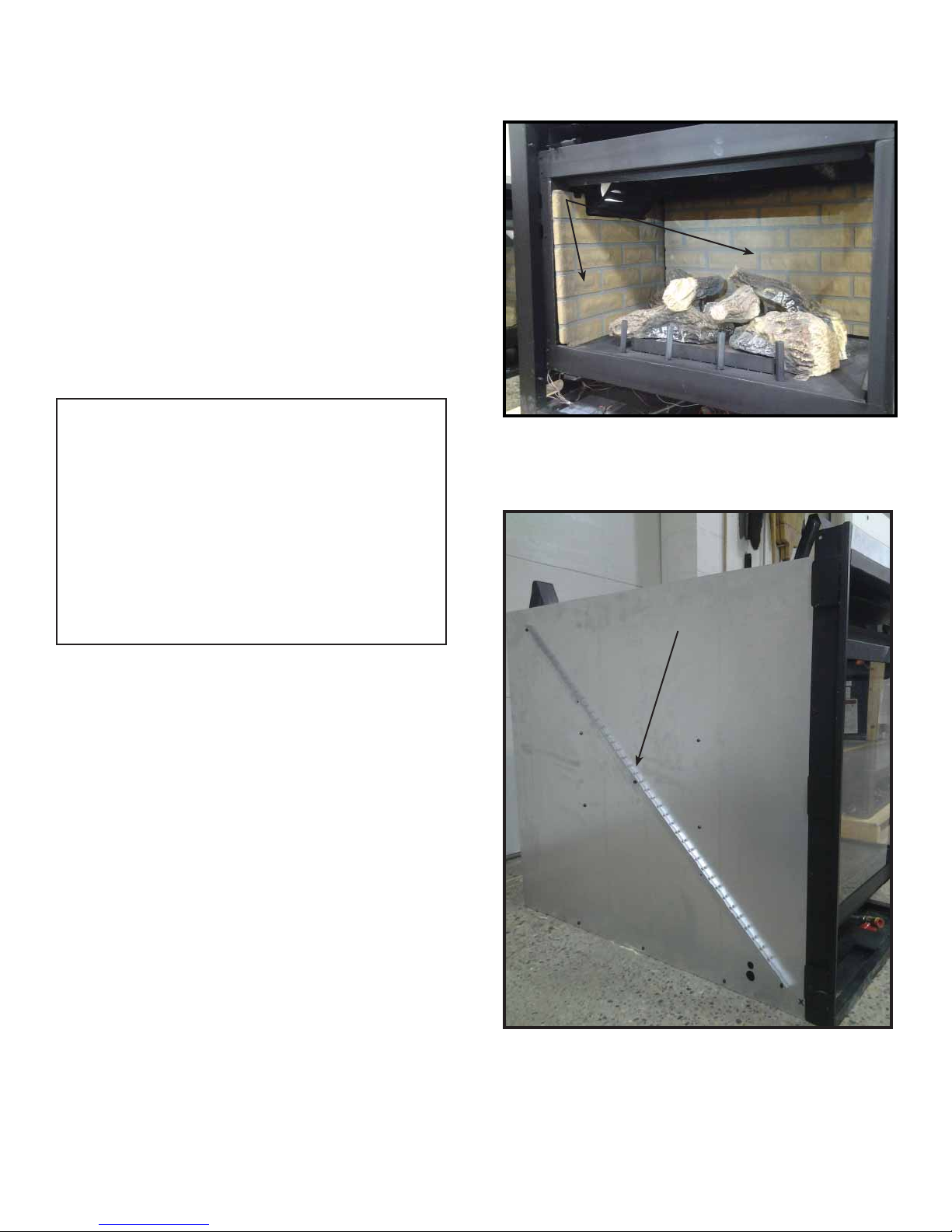
A. Remove Fixed Glass Assembly . . . . . . . . . . . . . . . . . . . . 58
B. Remove the Shipping Materials . . . . . . . . . . . . . . . . . . . . 58
C. Clean the Appliance . . . . . . . . . . . . . . . . . . . . . . . . . . . . . 58
D. Accessories . . . . . . . . . . . . . . . . . . . . . . . . . . . . . . . . . . . 58
E. Lava Rock and Glowing Ember Placement . . . . . . . . . . . 58
F. Install the Log Assembly. . . . . . . . . . . . . . . . . . . . . . . . . . 59
G. Fixed Glass Assembly . . . . . . . . . . . . . . . . . . . . . . . . . . . 62
H. Install Trim Kits and Surrounds . . . . . . . . . . . . . . . . . . . . 62
I. Air Shutter Setting . . . . . . . . . . . . . . . . . . . . . . . . . . . . . . 62
15 Troubleshooting
A. Intellifi re Ignition System . . . . . . . . . . . . . . . . . . . . . . . . . 63
16 Reference Materials
A. Appliance Dimension Diagram . . . . . . . . . . . . . . . . . . . . . 65
B. Vent Components Diagrams . . . . . . . . . . . . . . . . . . . . . . 68
C. Service Parts . . . . . . . . . . . . . . . . . . . . . . . . . . . . . . . . . . 77
D. Contact Information . . . . . . . . . . . . . . . . . . . . . . . . . . . . . 84
Heatilator • GDST4336I, GDFL4136I, GDCR4136I, GDCL4136I • 2129-900 Rev. W • 12/154
= Contains updated information.
Parts Labor Gas Wood Pellet
EPA
Wood
Coal Electric Venting
XXXXXXX
All parts and material except as
covered by Conditions,
Exclusions, and Limitations
listed
Igniters, electronic components,
and glass
XXXXX Factory-installed blowers
X Firepots and burnpots
5 years 1 year X X Castings and baffles
7 years 3 years X X X
Manifold tubes,
HHT chimney and termination
10
years
1 year X Burners, logs and refractory
Limited
Lifetime
3 yearsXXXXX Firebox and heat exchanger
XXXXXXX
All replacement parts
beyond warranty period
Warranty Period
HHT Manufactured Appliances and Venting
1 Year
Components Covered
3 years
2 years
90 Days
B. Limited Lifetime Warranty
Hearth & Home Technologies
LIMITED LIFETIME WARRANTY
Hearth & Home Technologies, on behalf of its hearth brands (“HHT”), extends the following warranty for HHT
gas, wood, pellet, coal and electric hearth appliances that are purchased from an HHT authorized dealer.
WARRANTY COVERAGE:
HHT warrants to the original owner of the HHT appliance at the site of installation, and to any transferee taking ownership
of the appliance at the site of installation within two years following the date of original purchase, that the HHT appliance
will be free from defects in materials and workmanship at the time of manufacture. After installation, if covered components manufactured by HHT are found to be defective in materials or workmanship during the applicable warranty period,
HHT will, at its option, repair or replace the covered components. HHT, at its own discretion, may fully discharge all of its
obligations under such warranties by replacing the product itself or refunding the verified purchase price of the product
itself. The maximum amount recoverable under this warranty is limited to the purchase price of the product. This warranty
is subject to conditions, exclusions and limitations as described below.
WARRANTY PERIOD:
Warranty coverage begins on the date of original purchase. In the case of new home construction, warranty coverage
begins on the date of first occupancy of the dwelling or six months after the sale of the product by an independent,
authorized HHT dealer/ distributor, whichever occurs earlier. The warranty shall commence no later than 24 months
following the date of product shipment from HHT, regardless of the installation or occupancy date. The warranty period for
parts and labor for covered components is produced in the following table.
The term “Limited Lifetime” in the table below is defined as: 20 years from the beginning date of warranty coverage for
gas appliances, and 10 years from the beginning date of warranty coverage for wood, pellet, and coal appliances. These
time periods reflect the minimum expected useful lives of the designated components under normal operating conditions.
XXX
X Molded refractory panels
X
See conditions, exclusions, and limitations on next page.
4021-645H 10/15 Page 1 of 2
Heatilator • GDST4336I, GDFL4136I, GDCR4136I, GDCL4136I • 2129-900 Rev. W • 12/15
Ignition Modules
5

B. Limited Lifetime Warranty (continued)
WARRANTY CONDITIONS:
• This warranty only covers HHT appliances that are purchased through an HHT authorized dealer or distributor. A list of
HHT authorized dealers is available on the HHT branded websites.
• This warranty is only valid while the HHT appliance remains at the site of original installation.
• This warranty is only valid in the country in which the HHT authorized dealer or distributor that sold the appliance
resides.
• Contact your installing dealer for warranty service. If the installing dealer is unable to provide necessary parts, contact
the nearest HHT authorized dealer or supplier. Additional service fees may apply if you are seeking warranty service
from a dealer other than the dealer from whom you originally purchased the product.
• Check with your dealer in advance for any costs to you when arranging a warranty call. Travel and shipping charges
for parts are not covered by this warranty.
WARRANTY EXCLUSIONS:
This warranty does not cover the following:
• Changes in surface finishes as a result of normal use. As a heating appliance, some changes in color of interior and
exterior surface finishes may occur. This is not a flaw and is not covered under warranty.
• Damage to printed, plated, or enameled surfaces caused by fingerprints, accidents, misuse, scratches, melted items,
or other external sources and residues left on the plated surfaces from the use of abrasive cleaners or polishes.
• Repair or replacement of parts that are subject to normal wear and tear during the warranty period. These parts
include: paint, wood, pellet and coal gaskets, firebricks, grates, flame guides, batteries and the discoloration of glass.
• Expansion, contraction, or movement of certain parts causing noise. These conditions are normal and complaints
related to this noise are not covered by this warranty.
• Damages resulting from: (1) failure to install, operate, or maintain the appliance in accordance with the installation
instructions, operating instructions, and listing agent identification label furnished with the appliance; (2) failure to
install the appliance in accordance with local building codes; (3) shipping or improper handling; (4) improper operation, abuse, misuse, continued operation with damaged, corroded or failed components, accident, or improperly/
incorrectly performed repairs; (5) environmental conditions, inadequate ventilation, negative pressure, or drafting
caused by tightly sealed constructions, insufficient make-up air supply, or handling devices such as exhaust fans or
forced air furnaces or other such causes; (6) use of fuels other than those specified in the operating instructions; (7)
installation or use of components not supplied with the appliance or any other components not expressly authorized
and approved by HHT; (8) modification of the appliance not expressly authorized and approved by HHT in writing;
and/or (9) interruptions or fluctuations of electrical power supply to the appliance.
• Non-HHT venting components, hearth components or other accessories used in conjunction with the appliance.
• Any part of a pre-existing fireplace system in which an insert or a decorative gas appliance is installed.
• HHT’s obligation under this warranty does not extend to the appliance’s capability to heat the desired space. Information is provided to assist the consumer and the dealer in selecting the proper appliance for the application. Consideration must be given to appliance location and configuration, environmental conditions, insulation and air tightness of
the structure.
This warranty is void if:
• The appliance has been over-fired or operated in atmospheres contaminated by chlorine, fluorine, or other damaging
chemicals. Over-firing can be identified by, but not limited to, warped plates or tubes, rust colored cast iron, bubbling,
cracking and discoloration of steel or enamel finishes.
• The appliance is subjected to prolonged periods of dampness or condensation.
• There is any damage to the appliance or other components due to water or weather damage which is the result of, but
not limited to, improper chimney or venting installation.
LIMITATIONS OF LIABILITY:
• The owner’s exclusive remedy and HHT’s sole obligation under this warranty, under any other warranty, express or
implied, or in contract, tort or otherwise, shall be limited to replacement, repair, or refund, as specified above. In no
event will HHT be liable for any incidental or consequential damages caused by defects in the appliance. Some states
do not allow exclusions or limitation of incidental or consequential damages, so these limitations may not apply to you.
This warranty gives you specific rights; you may also have other rights, which vary from state to state. EXCEPT TO
THE EXTENT PROVIDED BY LAW, HHT MAKES NO EXPRESS WARRANTIES OTHER THAN THE WARRANTY
SPECIFIED HEREIN. THE DURATION OF ANY IMPLIED WARRANTY IS LIMITED TO DURATION OF THE
EXPRESSED WARRANTY SPECIFIED ABOVE.
4021-645H 10/15 Page 2 of 2
Heatilator • GDST4336I, GDFL4136I, GDCR4136I, GDCL4136I • 2129-900 Rev. W • 12/156
1
1
Listing and Code Approvals
A. Appliance Certifi cation
MODELS: GDST4336I, GDFL4136I, GDCR4136I, GDCL4136I
LABORATORY: Underwriters Laboratories, Inc. (UL)
TYPE: Direct Vent Gas Appliance Heater
STANDARD: ANSI Z21.88-2014 • CSA 2.33-2014
This product is listed to ANSI standards for “Vented Gas
Appliance Heaters” and applicable sections of “Gas Burning Heating Appliances for Manufactured Homes and
Recreational Vehicles”, and “Gas Fired Appliances for
Use at High Altitudes”.
NOTICE: This installation must conform with local codes.
In the absence of local codes you must comply with the
National Fuel Gas Code, ANSI Z223.1-latest edition in
the U.S.A. and the CAN/CGA B149 Installation Codes in
Canada.
NOT INTENDED FOR USE AS A PRIMARY HEAT SOURCE.
This appliance is tested and approved as either supplemental room heat or as a decorative appliance. It should not be
factored as primary heat in residential heating calculations.
B. Tempered Glass Specifi cations
Hearth & Home Technologies appliances manufactured
with tempered glass may be installed in hazardous locations such as bathtub enclosures as defi ned by the Con-
sumer Product Safety Commission (CPSC). The tempered
glass has been tested and certifi ed to the requirements
of ANSI Z97.1 and CPSC 16 CFR 1202 (Safety Glazing
Certifi cation Council SGCC# 1595 and 1597. Architectur-
al Testing, Inc. Reports 02-31919.01 and 02-31917.01).
This statement is in compliance with CPSC 16 CFR Sec-
tion 1201.5 “Certifi cation and labeling requirements”
which refers to 15 U.S. Code (USC) 2063 stating “…Such
certifi cate shall accompany the product or shall otherwise
be furnished to any distributor or retailer to whom the
product is delivered.”
Some local building codes require the use of tempered
glass with permanent marking in such locations. Glass
meeting this requirement is available from the factory.
Please contact your dealer or distributor to order.
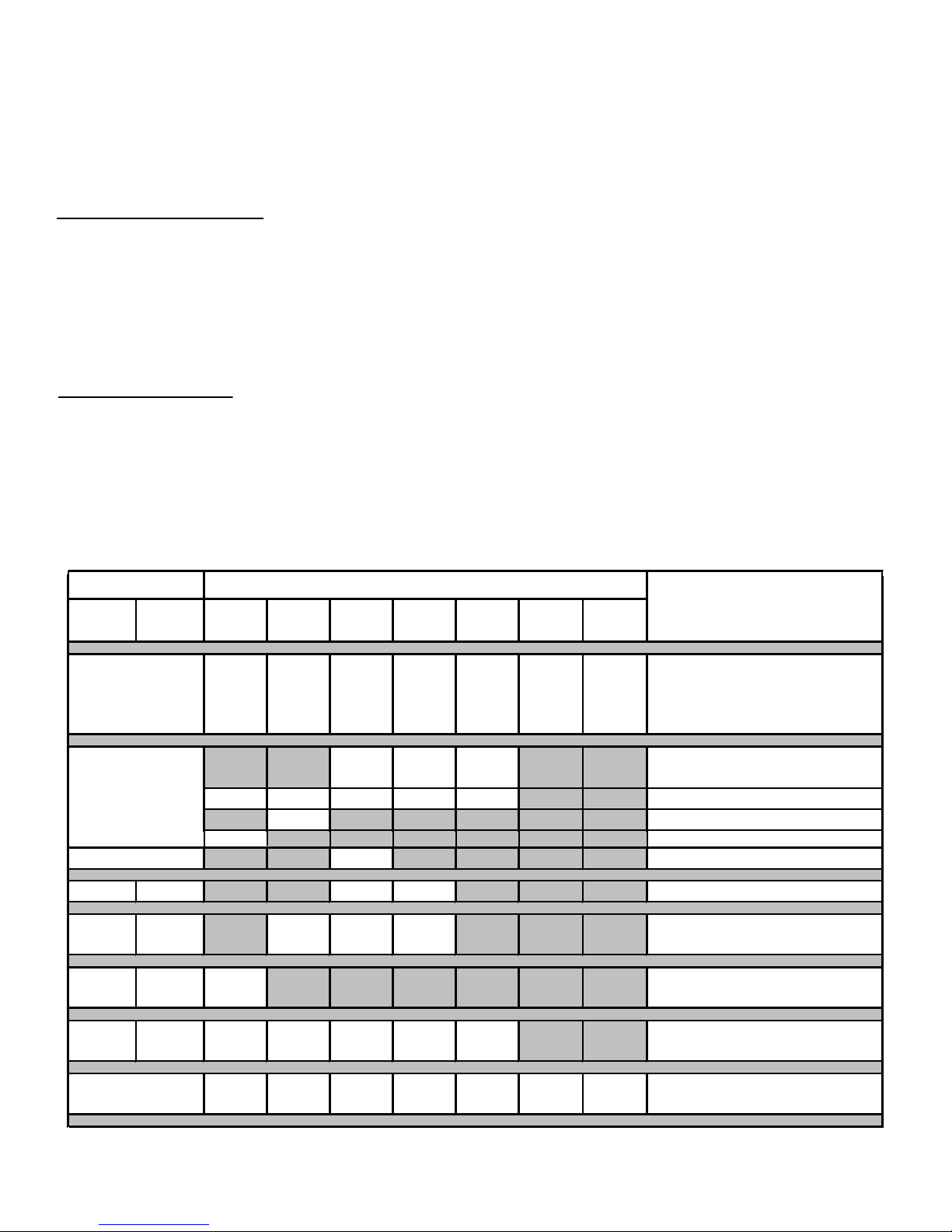
C. BTU Specifi cations
Models
(U.S. or Canada)
GDST4336I (NG)
GDFL4136I (NG)
GDCR4136I (NG)
GDCL4136I (NG)
GDST4336I (LP)
GDFL4136I (LP)
GDCR4136I (LP)
GDCL4136I (LP)
US
(0-2000 FT)
CANADA
(2000-4500FT)
US
(0-2000 FT)
CANADA
(2000-4500FT)
Maximum
Input
BTU/h
37,000 26,000 32
33,300 23,400 33
36,000 27,000 50
32.400 24,300 51
Minimum
Input
BTU/h
Orifi ce
Size
(DMS)
D. High Altitude Installations
NOTICE: If the heating value of the gas has been reduced,
these rules do not apply. Check with your local gas utility
or authorities having jurisdiction.
When installing above 2000 feet elevation:
• In the USA: Reduce input rate 4% for each 1000 feet
above 2000 feet.
• In CANADA: Reduce input rate 10% for elevations
between 2000 feet and 4500 feet. Above 4500 feet,
consult local gas utility.
Check with your local gas utility to determine proper orifi ce
size.
E. Non-Combustible Materials Specifi cation
Material which will not ignite and burn. Such materials
are those consisting entirely of steel, iron, brick, tile, concrete, slate, glass or plasters, or any combination thereof.
Materials that are reported as passing ASTM E 136,
Standard Test Method for Behavior of Materials in
a Vertical Tube Furnace at 750 ºC shall be considered
non-combustible materials.
F. Combustible Materials Specifi cation
Materials made of or surfaced with wood, compressed paper, plant fi bers, plastics, or other material that can ignite
and burn, whether fl ame proofed or not, or plastered or
unplastered shall be considered combustible materials.
G. Electrical Codes
NOTICE: This appliance must be electrically wired and
grounded in accordance with local codes or, in the absence
of local codes, with National Electric Code ANSI/NFPA
70-latest edition or the Canadian Electric Code CSA C22.1.
• A 110-120 VAC circuit for this product must be protected with
ground-fault circuit-interrupter protection, in compliance
with the applicable electrical codes, when it is installed in
locations such as in bathrooms or near sinks.
Heatilator • GDST4336I, GDFL4136I, GDCR4136I, GDCL4136I • 2129-900 Rev. W • 12/15
7

Note: The following requirements reference various
Massachusetts and national codes not contained in this
document.
H. Requirements for the Commonwealth of
Massachusetts
For all side wall horizontally vented gas fueled equipment
installed in every dwelling, building or structure used in
whole or in part for residential purposes, including those
owned or operated by the Commonwealth and where the
side wall exhaust vent termination is less than seven (7)
feet above fi nished grade in the area of the venting, in-
cluding but not limited to decks and porches, the following
requirements shall be satisfi ed:
Installation of Carbon Monoxide Detectors
At the time of installation of the side wall horizontal vented
gas fueled equipment, the installing plumber or gas fi tter
shall observe that a hard wired carbon monoxide detector
with an alarm and battery back-up is installed on the fl oor
level where the gas equipment is to be installed. In addition, the installing plumber or gas fi tter shall observe that
a battery operated or hard wired carbon monoxide detector with an alarm is installed on each additional level of
the dwelling, building or structure served by the side wall
horizontal vented gas fueled equipment. It shall be the
responsibility of the property owner to secure the services
of qualifi ed licensed professionals for the installation of
hard wired carbon monoxide detectors.
In the event that the side wall horizontally vented gas fueled equipment is installed in a crawl space or an attic,
the hard wired carbon monoxide detector with alarm and
battery back-up may be installed on the next adjacent
fl oor level.
In the event that the requirements of this subdivision can
not be met at the time of completion of installation, the
owner shall have a period of thirty (30) days to comply
with the above requirements; provided, however, that during said thirty (30) day period, a battery operated carbon
monoxide detector with an alarm shall be installed.
Inspection
The state or local gas inspector of the side wall horizontally vented gas fueled equipment shall not approve the
installation unless, upon inspection, the inspector observes carbon monoxide detectors and signage installed
in accordance with the provisions of 248 CMR 5.08(2)(a)1
through 4.
Exemptions
The following equipment is exempt from 248 CMR
5.08(2)(a)1 through 4:
• The equipment listed in Chapter 10 entitled “Equipment
Not Required To Be Vented” in the most current edition
of NFPA 54 as adopted by the Board; and
• Product Approved side wall horizontally vented gas fueled equipment installed in a room or structure separate
from the dwelling, building or structure used in whole or
in part for residential purposes.
MANUFACTURER REQUIREMENTS
Gas Equipment Venting System Provided
When the manufacturer of Product Approved side wall
horizontally vented gas equipment provides a venting
system design or venting system components with the
equipment, the instructions provided by the manufacturer
for installation of the equipment and the venting system
shall include:
• Detailed instructions for the installation of the venting
system design or the venting system components; and
• A complete parts list for the venting system design or
venting system.
Gas Equipment Venting System NOT Provided
When the manufacturer of a Product Approved side wall
horizontally vented gas fueled equipment does not provide the parts for venting the fl ue gases, but identifi es
“special venting systems”, the following requirements
shall be satisfi ed by the manufacturer:
Approved Carbon Monoxide Detectors
Each carbon monoxide detector as required in accordance with the above provisions shall comply with NFPA
720 and be ANSI/UL 2034 listed and IAS certifi ed.
Signage
A metal or plastic identifi cation plate shall be permanent-
ly mounted to the exterior of the building at a minimum
height of eight (8) feet above grade directly in line with the
exhaust vent terminal for the horizontally vented gas fueled heating appliance or equipment. The sign shall read,
in print size no less than one-half (1/2) inch in size, “GAS
VENT DIRECTLY BELOW. KEEP CLEAR OF ALL OBSTRUCTIONS”.
Heatilator • GDST4336I, GDFL4136I, GDCR4136I, GDCL4136I • 2129-900 Rev. W • 12/158
• The referenced “special venting system” instructions
shall be included with the appliance or equipment installation instructions; and
• The “special venting systems” shall be Product Approved by the Board, and the instructions for that system shall include a parts list and detailed installation
instructions.
A copy of all installation instructions for all Product Approved side wall horizontally vented gas fueled equipment, all venting instructions, all parts lists for venting
instructions, and/or all venting design instructions shall
remain with the appliance or equipment at the completion
of the installation.
See Gas Connection section for additional Commonwealth of Massachusetts requirements.
2
2
User Guide
Operating Instructions
A. Gas Fireplace Safety
WARNING! DO NOT operate fi replace before reading
and understanding operating instructions. Failure
to operate fi replace according to operating instructions
could cause fi re or injury.
DANGER
HOT GLASS WILL
CAUSE BURNS.
DO NOT TOUCH GLASS
UNTIL COOLED.
NEVER ALLOW CHILDREN
TO TOUCH GLASS.
• Keep children away.
• CAREFULLY SUPERVISE children in same room
as fi replace.
• Alert children and adults to hazards of high
temperatures.
High temperatures may ignite clothing or other
fl ammable materials.
• Clothing, furniture, draperies, and other fl ammable
materials must not be placed on or near the
appliance.
• Teach children to NEVER touch the fi replace.
• Consider not using the fi replace when children will be
present.
Contact your dealer for more information, or visit: www.
hpba.org/safety-information.
To prevent unintended operation when not using your fi re-
place for an extended period of time (summer months,
vacations, trips, etc):
• Remove batteries from remote controls.
• Turn off wall controls.
• Unplug 3 volt adapter plug and remove batteries on IPI
models.
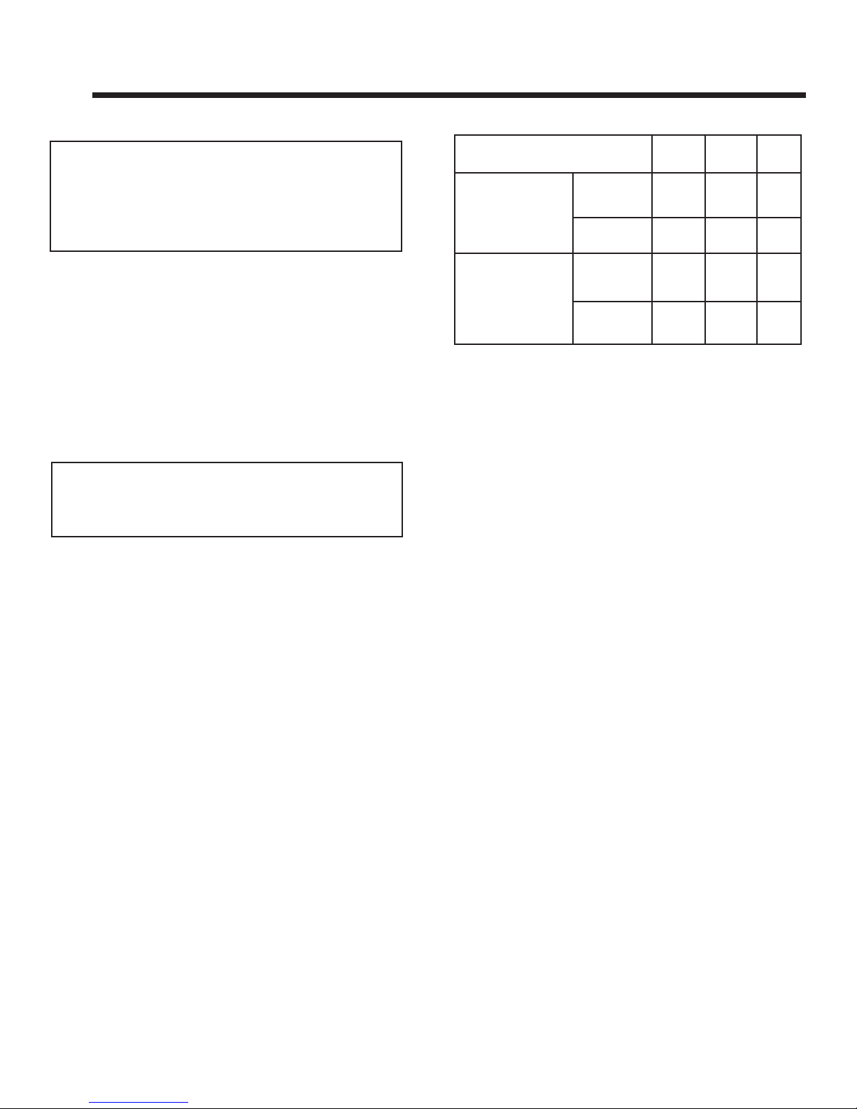
B. Your Fireplace
WARNING! DO NOT operate fi replace before read-
ing and understanding operating instructions. Failure
to operate fi replace according to operating instructions
could cause fi re or injury.
A barrier designed to reduce the risk of burns from the
hot viewing glass is provided with this appliance and
shall be installed for the protection of children and other
at-risk individuals. DO NOT operate the appliance with
the barrier removed. If the barrier becomes damaged,
the barrier shall be replaced with the manufacturer’s
barrier for this appliance.
Contact your dealer or Hearth & Home Technologies if the
barrier is not present or help is needed to properly install one.
Young children should be carefully supervised when they
are in the same room as the appliance. Toddlers, young
children and others may be susceptible to accidental
contact burns.
• A physical barrier is recommended if there are at risk
individuals in the house.
• To restrict access to a fi replace or stove, install an
adjustable safety gate to keep toddlers, young children
and other at risk individuals out of the room and away
from hot surfaces.
• Install a switch lock or a wall/remote control with child
protection lockout feature.
• Keep remote controls out of reach of children.
• Never leave children alone near a hot fi replace, whether
operating or cooling down.
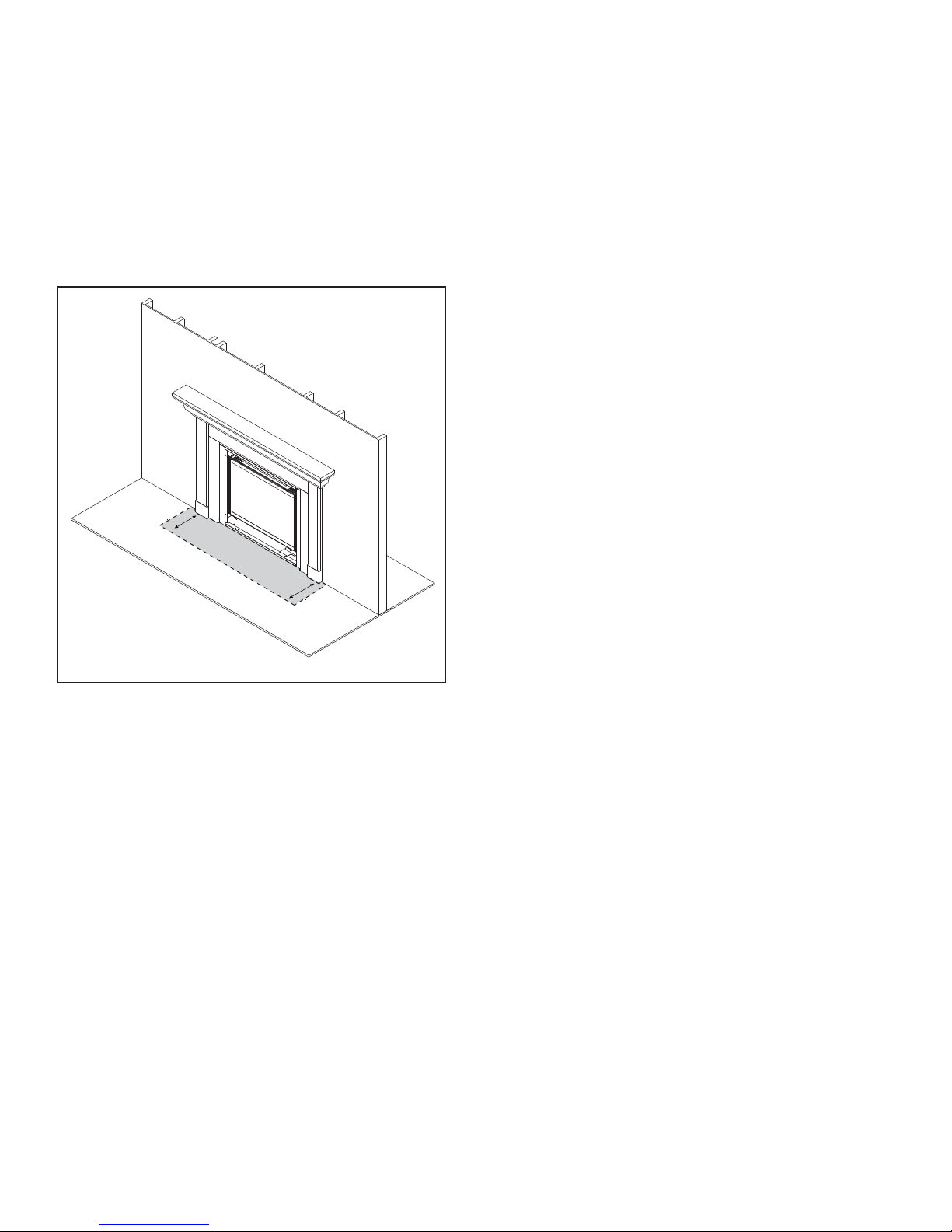
DECORATIVE DOORS
(NOT SHOWN)
SECTION 2.E.
FIXED GLASS ASSEMBLY
SECTION 14.K.
HEARTH
CLEAR SPACE
SECTION 2.D.
Figure 2.1 General Operating Parts
MANTEL
Heatilator • GDST4336I, GDFL4136I, GDCR4136I, GDCL4136I • 2129-900 Rev. W • 12/15
9
C. Fan Kit (optional)
If desired, a fan kit may be added. Contact your dealer to
order the correct fan kit.
D. Clear Space
WARNING! DO NOT place combustible objects in front
of the fi replace or block louvers. High temperatures may
start a fi re. See Figure 2.2.
Avoid placing candles and other heat-sensitive objects on
mantel or hearth. Heat may damage these objects.
3 FT. IN FRONT OF FIREPLACE
CLEAR SPACE
Figure 2.2 Clear Space
F. Fixed Glass Assembly
See Section 14.G.
G. Remote Controls, Wall Controls and Wall
Switches
Follow the instructions supplied with the control installed
to operate your fi replace:
For safety:
• Install a switch lock or a wall/remote control with child
protection lockout feature.
• Keep remote controls out of reach of children.
See your dealer if you have questions.
H. Before Lighting Fireplace
Before operating this fi replace for the fi rst time, have a
qualifi ed service technician:
• Verify all shipping materials have been removed from
inside and/or underneath the fi rebox.
• Review proper placement of logs, ember material and/or
other decorative materials.
• Check the wiring.
• Check the air shutter adjustment.
• Ensure that there are no gas leaks.
• Ensure that the glass is sealed and in the proper position
and that the integral barrier is in place.
WARNING! Risk of Fire or Asphyxiation! DO NOT operate fi replace with fi xed glass assembly removed.
E. Decorative Doors and Fronts
WARNING! Risk of Fire! Install ONLY doors or fronts
approved by Hearth & Home Technologies. Unapproved
doors or fronts may cause fi replace to overheat.
This fireplace has been supplied with an integral
barrier to prevent direct contact with the fi xed glass
panel. DO NOT operate the fi replace with the barrier
removed.
Contact your dealer or Hearth & Home Technologies if
the barrier is not present or help is needed to properly
install one.
For more information refer to the instructions supplied with
your decorative door or front.
Heatilator • GDST4336I, GDFL4136I, GDCR4136I, GDCL4136I • 2129-900 Rev. W • 12/1510
I. Lighting Instructions (IPI)
The IPI system may be operated with two D-cell batteries. When using batteries, unplug the transformer. To prolong battery
life, remove them when using the transformer.
FOR YOUR SAFETY READ BEFORE LIGHTING
WARNING: If you do not follow these instructions exactly, a fi re or explosion may result causing property damage, personal injury or loss of life.
A. This appliance is equipped with an intermittent pilot ignition (IPI) device which
automatically lights the burner. DO NOT try to light the burner by hand.
B. BEFORE LIGHTING, smell all around the appliance area for gas. Be sure to smell
next to the fl oor because some gas is heavier than air and will settle on the fl oor.
WHAT TO DO IF YOU SMELL GAS
• DO NOT try to light any appliance.
• DO NOT touch any electric switch; do not use any phone in your building.
• Immediately call your gas supplier from a neighbor’s phone. Follow the gas supplier’s instructions.
• If you cannot reach your gas supplier, call the fi re department.
C. Use only your hand to push in or turn the gas control knob. Never use tools. If
the knob will not push in or turn by hand, DO NOT try to repair it, call a qualifi ed
service technician. Force or attempted repair may result in a fi re or explosion.
D. DO NOT use this appliance if any part has been under water. Immediately call
a qualifi ed service technician to inspect the appliance and to replace any part of
the control system and any gas control which has been under water.
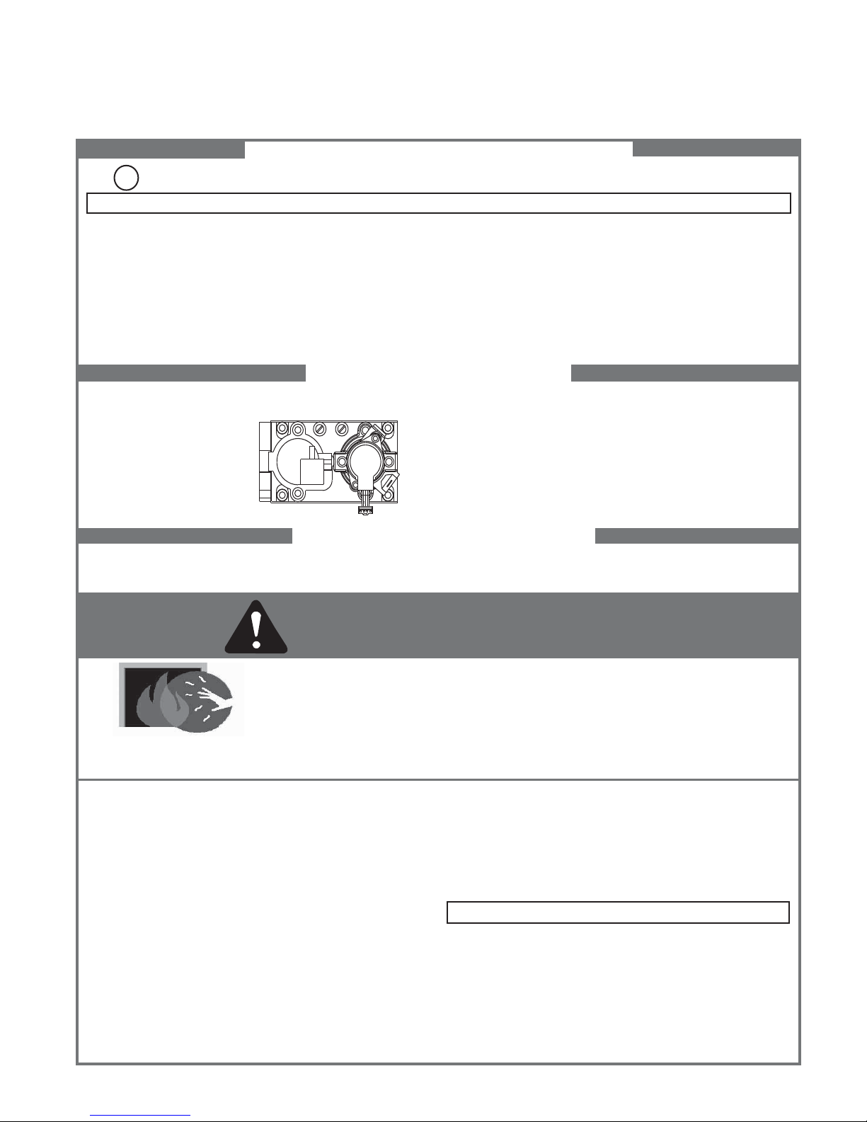
LIGHTING INSTRUCTIONS (IPI)
1. This appliance is equipped with an ignition device which
automatically lights the burner. DO NOT try to light the burner by hand.
GAS
VALVE
2. Wait fi ve (5) minutes to clear out any gas. Then smell for gas, including near the
fl oor. If you smell gas, STOP! Follow “B” in the Safety Information located on the
top of this label. If you do not smell gas, go to next step.
3. To light the burner:
Equipped with wall switch: Turn ON/OFF switch to ON.
Equipped with remote or wall control: Press ON or FLAME button.
Equipped with thermostat: Set temperature to desired setting.
4. If the appliance does not light after three tries, call your service technician or gas
supplier.
TO TURN OFF GAS TO APPLIANCE
1. Equipped with wall switch: Turn ON/OFF switch to OFF.
Equipped with remote or wall control: Press OFF button.
Equipped with thermostat: Set temperature to lowest setting.
2. Service technician should turn off electric power to the control when performing
service.
DANGER
HOT GLASS WILL CAUSE BURNS.
DO NOT TOUCH GLASS UNTIL COOLED.
NEVER ALLOW CHILDREN TO TOUCH GLASS.
A barrier designed to reduce the risk of burns from the hot viewing glass is provided with this
appliance and shall be installed for the protection of children and other at-risk individuals.
WARNING:
DO NOT CONNECT LINE VOLTAGE (110/120 VAC OR 220/240 VAC) TO THE CONTROL VALVE.
Improper installation, adjustment, alteration, service or maintenance can cause
injury or property damage. Refer to the owner’s information manual provided with
this appliance. For assistance or additional information, consult a qualifi ed installer,
service agency or the gas supplier.
This appliance needs fresh air for safe operation and must be installed so there are
provisions for adequate combustion and ventilation air.
If not installed, operated, and maintained in accordance with the manufacturer’s instructions, this product could expose you to substances in fuel or fuel combustion which
are known to the State of California to cause cancer, birth defects, or other reproductive
harm.
Keep burner and control compartment clean. See installation and operating instructions accompanying appliance.
Hearth & Home Technologies fi replace, please refer to www.fi replaces.com.
For additional information on operating your
CAUTION:
Hot while in operation. DO NOT touch. Keep children, clothing, furniture, gasoline
and other liquids having fl ammable vapors away.
DO NOT operate the appliance with fi xed glass assembly removed, cracked or
broken. Replacement of the fi xed glass assembly should be done by a licensed or
qualifi ed service person.
NOT FOR USE WITH SOLID FUEL
For use with natural gas and propane. A conversion kit, as supplied by the manufacturer, shall be used to convert this appliance to the alternate fuel.
Also Certifi ed for Installation in a Bedroom or a Bedsitting Room.
This appliance must be installed in accordance with local codes, if any; if none,
follow the National Fuel Gas Code, ANSIZ223.1/ NFPA 54, or the National Gas and
Propane Installation code, CSA B149.1.
593-913i
Heatilator • GDST4336I, GDFL4136I, GDCR4136I, GDCL4136I • 2129-900 Rev. W • 12/15
11
J. After Fireplace is Lit
Initial Break-in Procedure
• The fireplace should be run three to four hours
continuously on high.
• Turn the fi replace off and allow it to completely cool.
• Remove fi xed glass assembly. See Section 14.G.
• Clean fi xed glass assembly. See Section 3.
• Replace the fi xed glass assembly and run continuously
on high an additional 12 hours.
This cures the materials used to manufacture the fi re-
place.
NOTICE! Open windows for air circulation during fi re-
place break-in.
• Some people may be sensitive to smoke and odors.
• Smoke detectors may activate.
K. Frequently Asked Questions
ISSUE SOLUTIONS
Condensation on the glass
Blue fl ames
Odor from fi replace
Film on the glass
Metallic noise
Is it normal to see the pilot fl ame burn
continually?
This is a result of gas combustion and temperature variations. As the fi replace warms, this
condensation will disappear.
This is a result of normal operation and the fl ames will begin to yellow as the fi replace is al-
lowed to burn for 20 to 40 minutes.
When fi rst operated, this fi replace may release an odor for the fi rst several hours. This is
caused by the curing of materials from manufacturing. Odor may also be released from
fi nishing materials and adhesives used near the fi replace. These circumstances may require
additional curing related to the installation environment.
This is a normal result of the curing process of the paint and logs. Glass should be cleaned
within 3 to 4 hours of initial burning. A non-abrasive cleaner such as gas fi replace glass
cleaner may be necessary. See your dealer.
Noise is caused by metal expanding and contracting as it heats up and cools down, similar to
the sound produced by a furnace or heating duct. This noise does not affect the operation or
longevity of the fi replace.
In an intermittent pilot ignition system (IPI), the pilot fl ame should turn off when appliance is
turned off. Some optional control systems available with IPI models may allow pilot fl ame to
remain lit.
Heatilator • GDST4336I, GDFL4136I, GDCR4136I, GDCL4136I • 2129-900 Rev. W • 12/1512
3
3
Maintenance and Service
Any safety screen or guard removed for servicing must be
replaced prior to operating the fi replace.
When properly maintained, your fi replace will give you
many years of trouble-free service. We recommend annual service by a qualifi ed service technician.
A. Maintenance Tasks-Homeowner
Installation and repair should be done by a qualifi ed service
technician only. The fi replace should be inspected before
use and at least annually by a professional service person.
The following tasks may be performed annually by the
homeowner. If you are uncomfortable performing any of
the listed tasks, please call your dealer for a service appointment.
More frequent cleaning may be required due to lint from
carpeting or other factors. Control compartment, burner
and circulating air passageway of the fi replace must be
kept clean.
CAUTION! Risk of Burns! The fi replace should be turned
off and cooled before servicing.
Glass Cleaning
Frequency: Seasonally
By: Homeowner
Tools Needed: Protective gloves, glass cleaner, drop
cloth and a stable work surface.
CAUTION! Handle fi xed glass assembly with care.
Glass is breakable.
• Avoid striking, scratching or slamming glass
• Avoid abrasive cleaners
• DO NOT clean glass while it is hot
• Prepare a work area large enough to accommodate fi xed
glass assembly and door frame by placing a drop cloth
on a fl at, stable surface.
Note: Fixed glass assembly and gasketing may have residue that can stain carpeting or fl oor surfaces.
• Remove door or decorative front from fi replace and set
aside on work surface.
• See Section 14.G for instructions to remove fi xed glass
assembly.
• Clean glass with a non-abrasive commercially available
cleaner.
- Light deposits: Use a soft cloth with soap and water
- Heavy deposits: Use commercial fireplace glass
cleaner (consult with your dealer)
• Carefully set fi xed glass assembly in place on fi replace.
Hold glass in place with one hand and secure glass
latches with the other hand.
• Reinstall door or decorative front.
Heatilator • GDST4336I, GDFL4136I, GDCR4136I, GDCL4136I • 2129-900 Rev. W • 12/15
Doors, Surrounds, Fronts
Frequency: Annually
By: Homeowner
Tools needed: Protective gloves, stable work surface
• Assess condition of screen and replace as necessary.
• Inspect for scratches, dents or other damage and repair
as necessary.
• Check that louvers are not blocked.
• Vacuum and dust surfaces.
Remote Control
Frequency: Seasonally
By: Homeowner
Tools needed: Replacement batteries and remote con-
trol instructions.
• Locate remote control transmitter and receiver.
• Verify operation of remote. Refer to remote control
operation instructions for proper calibration and setup
procedure.
• Place batteries as needed in remote transmitters and
battery-powered receivers.
• Place remote control out of reach of children.
If not using your fi replace for an extended period of time
(summer months, vacations/trips, etc), to prevent unintended operation:
• Remove batteries from remote controls.
• Unplug 3 volt adapter plug on IPI models.
Venting
Frequency: Seasonally
By: Homeowner
Tools needed: Protective gloves and safety glasses.
• Inspect venting and termination cap for blockage or
obstruction such plants, bird nests, leaves, snow, debris,
etc.
• Verify termination cap clearance to subsequent construction (building additions, decks, fences, or sheds). See
Section 6.
• Inspect for corrosion or separation.
• Verify weather stripping, sealing and fl ashing remains
intact.
• Inspect draft shield to verify it is not damaged or missing.
13
B. Maintenance Tasks-Qualifi ed Service
Technician
The following tasks must be performed by a qualifi ed ser-
vice technician.
Gasket Seal and Glass Assembly Inspection
Frequency: Annually
By: Qualifi ed Service Technician
Tools needed: Protective gloves, drop cloth and a stable
work surface.
• Inspect gasket seal and its condition.
• Inspect fi xed glass assembly for scratches and nicks that
can lead to breakage when exposed to heat.
• Confi rm there is no damage to glass or glass frame.
Replace as necessary.
• Verify that fi xed glass assembly is properly retained and
attachment components are intact and not damaged.
Replace as necessary.
Logs
Frequency: Annually
By: Qualifi ed Service Technician
Tools needed: Protective gloves.
• Inspect for damaged or missing logs. Replace as necessary. Refer to Section 14 for log placement instructions.
• Verify correct log placement and no fl ame impingement
causing sooting. Correct as necessary.
Firebox
Frequency: Annually
By: Qualifi ed Service Technician
Tools needed: Protective gloves, sandpaper, steel wool,
cloths, mineral spirits, primer and touch-up paint.
• Inspect for paint condition, warped surfaces, corrosion
or perforation. Sand and repaint as necessary.
• Replace fi replace if fi rebox has been perforated.
Control Compartment and Firebox Top
Frequency: Annually
By: Qualifi ed Service Technician
Tools needed: Protective gloves, vacuum cleaner, dust
cloths
• Vacuum and wipe out dust, cobwebs, debris or pet hair.
Use caution when cleaning these areas. Screw tips that
have penetrated the sheet metal are sharp and should
be avoided.
• Remove all foreign objects.
• Verify unobstructed air circulation.
Burner Ignition and Operation
Frequency: Annually
By: Qualifi ed Service Technician
Tools needed: Protective gloves, vacuum cleaner, whisk
broom, fl ashlight, voltmeter, indexed drill bit set, and a
manometer.
• Verify burner is properly secured and aligned with pilot
or igniter.
• Clean off burner top, inspect for plugged ports, corrosion
or deterioration. Replace burner if necessary.
• Replace Glowing embers with new dime-size pieces.
DO NOT block ports or obstruct lighting paths. Refer to
Section 14 for proper ember placement.
• Verify batteries have been removed from battery back-up
IPI systems to prevent premature battery failure or
leaking.
• Check for smooth lighting and ignition carryover to all
ports. Verify that there is no ignition delay.
• Inspect for lifting or other fl ame problems.
• Verify air shutter setting is correct. See Section 14 for
required air shutter setting. Verify air shutter is clear of
dust and debris.
• Inspect orifi ce for soot, dirt and corrosion. Verify orifi ce
size is correct. See Service Parts List for proper orifi ce
sizing.
• Verify manifold and inlet pressures. Adjust regulator as
required.
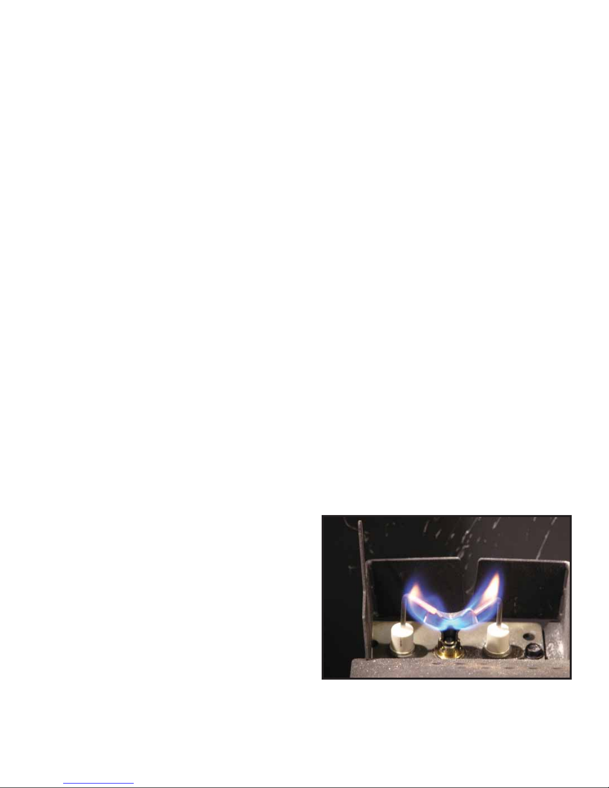
• Inspect pilot fl ame pattern and strength. See Figures 3.1
and 3.2 for proper pilot fl ame pattern. Clean or replace
orifi ce spud as necessary.
• Inspect IPI fl ame sensing rod for soot, corrosion and
deterioration. Polish with fi ne steel wool or replace as
required.
• Verify that there is not a short in fl ame sense circuit
by checking continuity between pilot hood and fl ame
sensing rod. Replace pilot as necessary.
Heatilator • GDST4336I, GDFL4136I, GDCR4136I, GDCL4136I • 2129-900 Rev. W • 12/1514
Figure 3.1 IPI Pilot Flame Patterns
4
Installer Guide
4
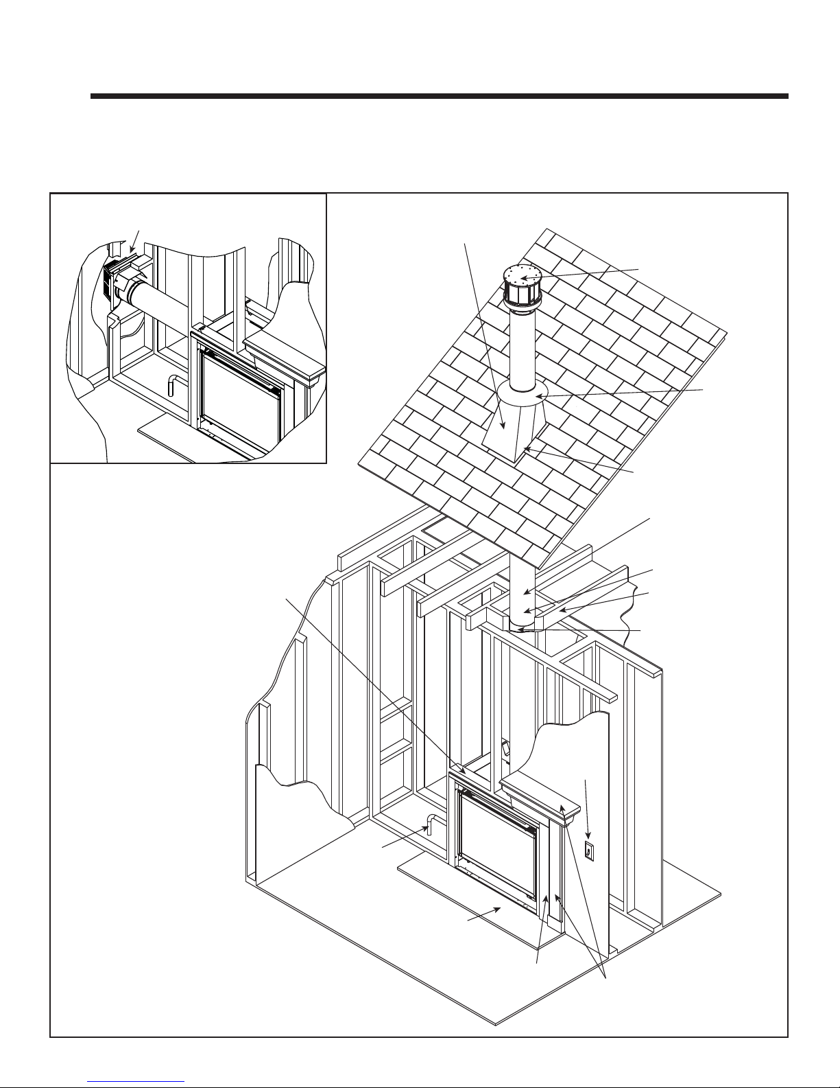
A. Typical Appliance System
NOTICE: Illustrations and photos refl ect typical installations and are for design purposes only. Illustrations/diagrams are not
drawn to scale. Actual product may vary from pictures in manual
Getting Started
HORIZONTAL
TERMINATION CAP
(SECTION 10.M)
FRAMING/HEADER
(SECTION 5.B)
NON-COMBUSTIBLE ROOF FLASHING
MAINTAINS MINIMUM CLEARANCE
AROUND PIPE (SECTION 10.D)
VERTICAL TERMINATION CAP
(SECTION 10.E)
STORM COLLAR
(SECTION 10.H)
VENT PIPE PENETRATES ROOF
PREFERABLY WITHOUT AFFECTING
ROOF RAFTERS (SECTION 8.D)
ATTIC INSULATION SHIELD (NOT
SHOWN) MUST BE USED HERE
TO KEEP INSULATION AWAY
FROM VENT PIPE IF ATTIC IS
INSULATED (SECTION 8.E)
VENT PIPE (SECTION 9 and 10)
FRAMING HEADED OFF
IN CEILING JOISTS
(SECTION 8.C)
CEILING FIRESTOP
ON FLOOR OF ATTIC
(SECTION 8.C)
Note: Dual venting configurations
ARE NOT allowed. Appliance MUST
be vented EITHER vertically OR
horizontally.
Figure 4.1 Typical System
Heatilator • GDST4336I, GDFL4136I, GDCR4136I, GDCL4136I • 2129-900 Rev. W • 12/15
GAS LINE
(SECTION 11.C)
HEARTH EXTENSION
SURROUND
OPTIONAL
WALL SWITCH
MANTEL AND
MANTEL LEG
(SECTION 5.D)
15

B. Design and Installation Considerations
Heatilator direct vent gas appliances are designed to operate with all combustion air siphoned from outside of the
building and all exhaust gases expelled to the outside. No
additional outside air source is required.
Installation MUST comply with local, regional, state and
national codes and regulations. Consult insurance carrier,
local building inspector, fi re offi cials or authorities having
jurisdiction over restrictions, installation inspection and
permits.
Before installing, determine the following:
• Where the appliance is to be installed.
• The vent system confi guration to be used.
• Gas supply piping requirements.
• Electrical wiring requirements.
• Framing and fi nishing details.
• Whether optional accessories—devices such as a fan,
wall switch, or remote control—are desired.
Improper installation, adjustment, alteration, service or
maintenance can cause injury or property damage. For
assistance or additional information, consult a qualifi ed
service technician, service agency or your dealer.
C. Tools and Supplies Needed
Before beginning the installation be sure that the following
tools and building supplies are available.
Tape measure Framing material
Pliers Non-corrosive leak check solution
Hammer Phillips screwdriver
Gloves Framing square
Voltmeter Electric drill and bits (1/4 in.)
Plumb line Safety glasses
Level Reciprocating saw
Manometer Flat blade screwdriver
1/2 - 3/4 in. length, #6 or #8 Self-drilling screws
Caulk (minimum of 300ºF continuous exposure rating)
One 1/4 in. female connection (for optional fan).
Installation and service of this
appliance should be performed by
qualifi ed personnel. Hearth & Home
Technologies recommends HHT
Factory Trained or NFI certified
professionals.
Heatilator • GDST4336I, GDFL4136I, GDCR4136I, GDCL4136I • 2129-900 Rev. W • 12/1516
D. Inspect Appliance and Components
DO NOT REMOVE STANDOFF
DO NOT REMOVE REFRACTORY
• Carefully remove the appliance and components from
the packaging.
• The vent system components and decorative fronts may
be shipped in separate packages.
• If packaged separately, the log set and appliance grate
must be installed.
• Report to your dealer any parts damaged in shipment,
particularly the condition of the glass.
• Read all of the instructions before starting the instal-
lation. Follow these instructions carefully during the
installation to ensure maximum safety and benefi t.
WARNING! Risk of Fire or Explosion! Damaged parts
could impair safe operation. DO NOT install damaged, in-
complete or substitute components. Keep appliance dry.
WARNING! Risk of Fire! DO NOT remove refractory.
Appliance could overheat!
DO NOT REMOVE REFRACTORY
Hearth & Home Technologies disclaims any responsibility for,
and the warranty will be voided by, the following actions:
• Installation and use of any damaged appliance or vent
system component.
• Modifi cation of the appliance or vent system.
• Installation other than as instructed by Hearth & Home
Technologies.
• Improper positioning of the gas logs or the glass door.
• Installation and/or use of any component part not approved
by Hearth & Home Technologies.
Any such action may cause a fi re hazard.
WARNING! Risk of Fire, Explosion or Electric Shock!
DO NOT use this appliance if any part has been under
water. Call a qualifi ed service technician to inspect the
appliance and to replace any part of the control system
and/or gas control which has been under water.
Figure 4.2 Do Not Remove Refractory
WARNING! Risk of Fire! DO NOT remove standoff.
Appliance could overheat!
DO NOT REMOVE STANDOFF
Heatilator • GDST4336I, GDFL4136I, GDCR4136I, GDCL4136I • 2129-900 Rev. W • 12/15
Figure 4.3 Do Not Remove Standoff
17
5
5
Framing and Clearances
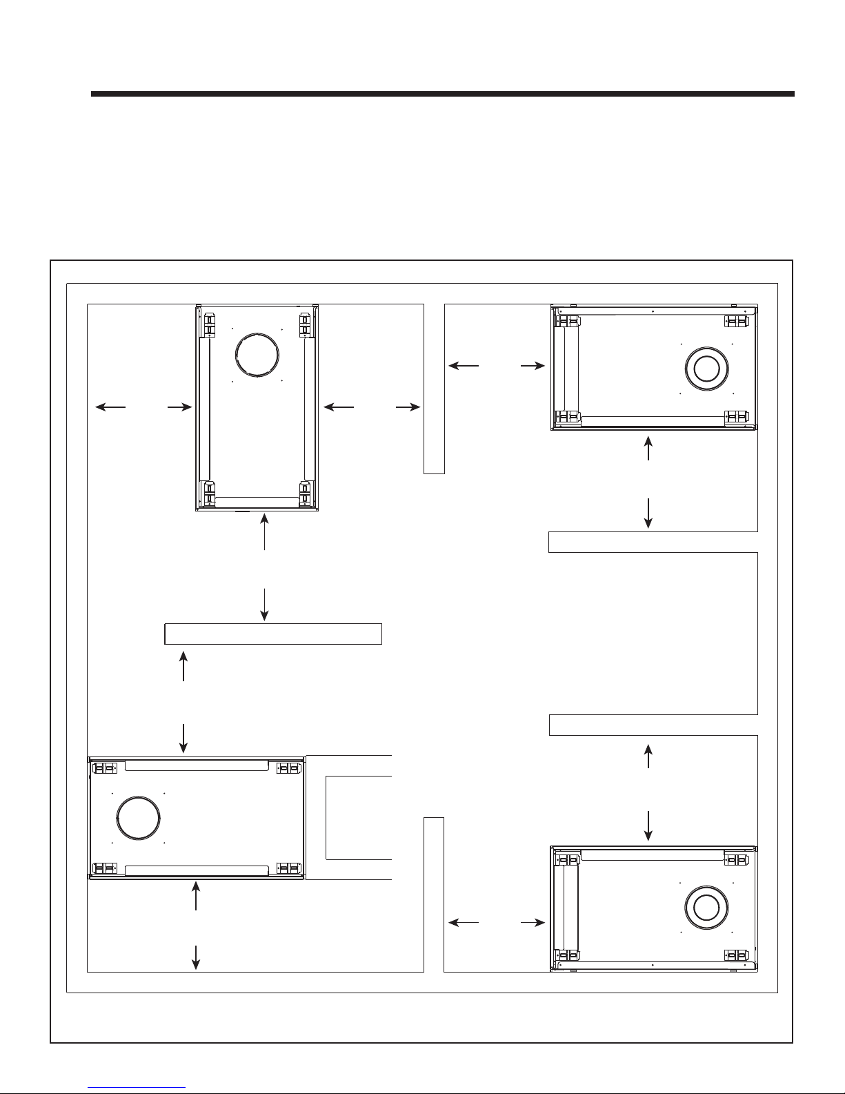
A. Selecting Appliance Location
When selecting a location for the appliance it is important to
consider the required clearances to walls (see Figure 5.1).
WARNING! Risk of Fire or Burns! Provide adequate
clearance around air openings and for service access.
Due to high temperatures, the appliance should be located out of traffi c and away from furniture and draperies.
36 in.
914 mm
GDFL4136I
36 in.
914 mm
NOTICE: Illustrations refl ect typical installations and are
FOR DESIGN PURPOSES ONLY. Illustrations/diagrams
are not drawn to scale. Actual installation may vary due to
individual design preference.
NOTICE: This See-Through appliance is NOT designed
or approved for an indoor/outdoor application.
36 in.
914 mm
GDCL4136I
36 in.
914 mm
36 in.
914 mm
GDST4336I
36 in.
914 mm
36 in.
914 mm
36 in.
914 mm
36 in.
914 mm
GDCR4136I
Figure 5.1 Appliance Locations
Heatilator • GDST4336I, GDFL4136I, GDCR4136I, GDCL4136I • 2129-900 Rev. W • 12/1518
B. Constructing the Appliance Chase
A chase is a vertical box-like structure built to enclose the
gas appliance and/or its vent system. In cooler climates
the vent should enclosed inside the chase.
NOTICE: Treatment of ceiling fi restops and wall shield
fi restops and construction of the chase may vary with the
type of building. These instructions are not substitutes
for the requirements of local building codes. Therefore,
you MUST check local building codes to determine the
requirements to these steps.
Chases should be constructed in the manner of all outside walls of the home to prevent cold air drafting problems. The chase should not break the outside building
envelope in any manner.
Walls, ceiling, base plate and cantilever fl oor of the chase
should be insulated. Vapor and air infi ltration barriers
should be installed in the chase as per regional codes for
the rest of the home. Additionally, in regions where cold
air infi ltration may be an issue, the inside surfaces may be
sheetrocked and taped for maximum air tightness.
To further prevent drafts, the wall shield and ceiling fi re-
stops should be caulked with caulk with a minimum of
300ºF continuous exposure rating to seal gaps. Gas line
holes and other openings should be caulked with caulk
with a minimum of 300ºF continuous exposure rating or
stuffed with unfaced insulation. If the appliance is being
installed on a cement surface, a layer of plywood may be
placed underneath to prevent conducting cold up into the
room.
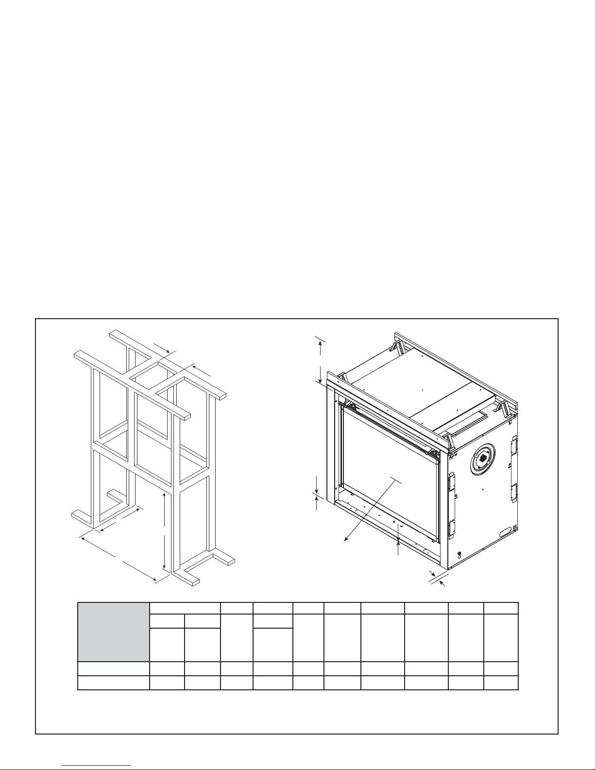
C. Clearances
NOTICE: Install appliance on hard metal or wood surfaces
extending full width and depth. DO NOT install directly
on carpeting, vinyl, tile or any combustible material other
than wood.
WARNING! Risk of Fire! Maintain specifi ed air space
clearances to appliance and vent pipe:
• Insulation and other materials must be secured to prevent
accidental contact.
• The chase must be properly blocked to prevent blown
insulation or other combustibles from entering and
making contact with fi replace or chimney.
• Failure to maintain airspace may cause overheating and
a fi re.
C
D
GDST4336I
Inches
Millimeters
A
E
I
F
B
G
H
ABCDEFGHI
DVP Pipe SLP Pipe
Rough
Opening
(Width)
10 8-5/8 38-1/8 23 43 34-1/8 0 0 1/2 36
254 219 968 584 1092 867 0 0 13 914
Rough
Opening
(Width)
Rough
Opening
(Height)
DVP Pipe*
Rough
Opening
(Depth)
Rough
Opening
(Width)
Clearance
to Ceiling
Combustible
Floor
Combustible
Flooring
Ends of
Appliance
Sides of
Appliance
* Adjust framing dimensions for interior sheathing (such as sheetrock)
Figure 5.2 Clearances to Combustibles
Heatilator • GDST4336I, GDFL4136I, GDCR4136I, GDCL4136I • 2129-900 Rev. W • 12/15
19
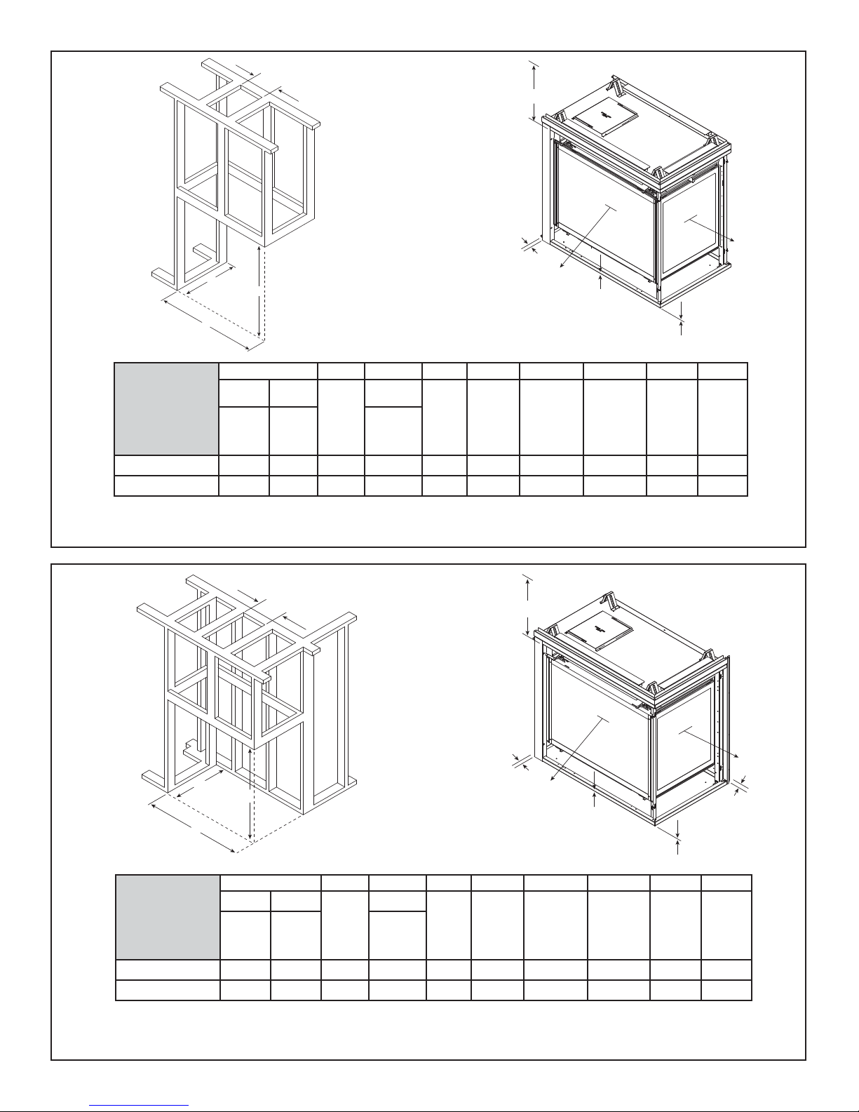
A
E
C
D
GDFL4136I
Inches
Millimeters
B
DVP Pipe SLP Pipe
Rough
Opening
(Width)
10 8-5/8 38-1/8 23 40 34-1/8 0 0 1/2 36
254 219 968 584 1016 867 0 0 13 914
* Adjust framing dimensions for interior sheathing (such as sheetrock)
Figure 5.3 Clearances to Combustibles
I
H
G
I
F
ABCDEFGHI
DVP Pipe*
Rough
Opening
(Depth)
Rough
Opening
(Width)
Clearance
to Ceiling
Combustible
Floor
E
Combustible
Flooring
Ends of
Appliance
Sides of
Appliance
Rough
Opening
(Width)
A
Rough
Opening
(Height)
C
D
B
ABCDEFGHI
DVP Pipe SLP Pipe
GDCR4136I
Inches
Millimeters
Rough
Opening
(Width)
Rough
Opening
(Width)
10 8-5/8 38-1/8 24 40 34-1/8 0 0 1/2 36
254 219 968 610 1016 867 0 0 13 914
* Adjust framing dimensions for interior sheathing (such as sheetrock)
Figure 5.4 Clearances to Combustibles
Heatilator • GDST4336I, GDFL4136I, GDCR4136I, GDCL4136I • 2129-900 Rev. W • 12/1520
Rough
Opening
(Height)
DVP Pipe*
Rough
Opening
(Depth)
Rough
Opening
(Width)
H
Clearance
to Ceiling
Combustible
Floor
I
G
Combustible
Flooring
I
F
Ends of
Appliance
H
Sides of
Appliance
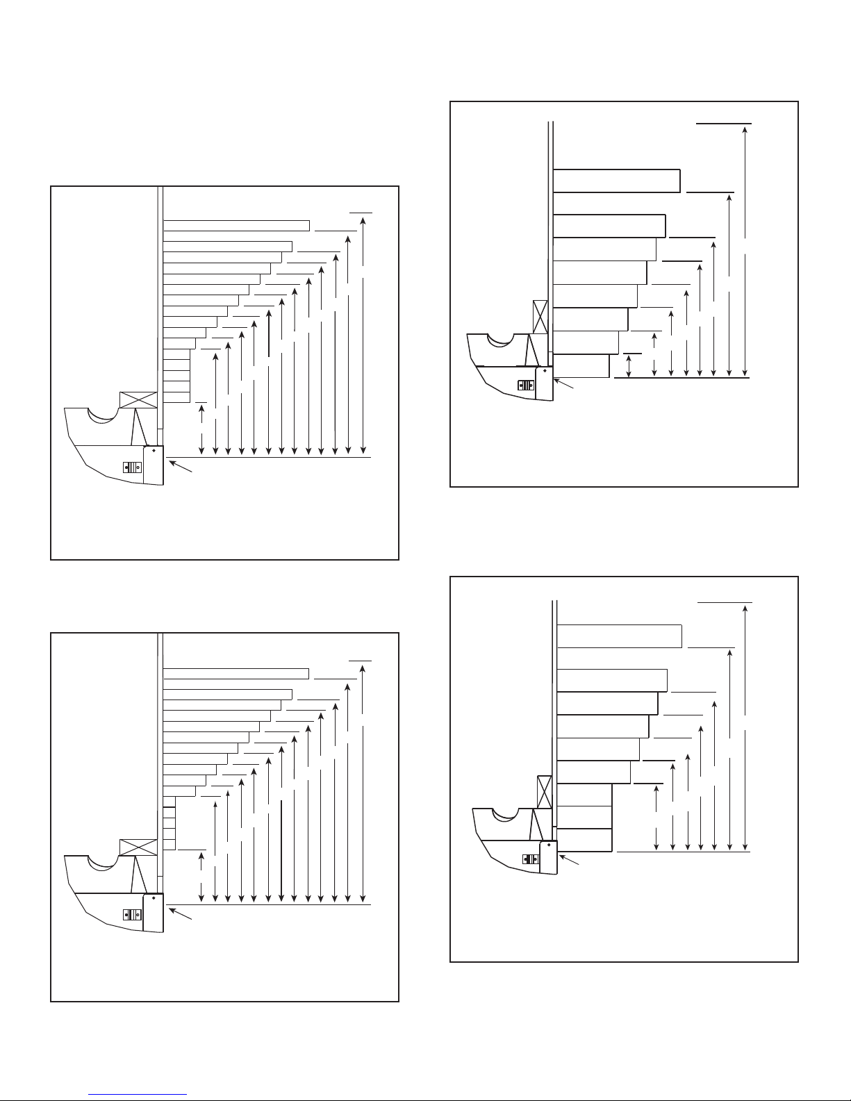
D. Mantel and Wall Projections
WARNING! Risk of Fire! Comply with all minimum clearances as specifi ed. Framing or fi nishing material closer than
the minimums listed must be constructed entirely of noncombustible materials (i.e., steel studs, concrete board, etc).
GDST4336I
Non-Combustible Mantel
TO CEILING
GDST4336I Combustible Mantel
Note: All
measurements
in inches.
2-1/2
Figure 5.5 Minimum Vertical and Maximum Horizontal
Dimensions of Combustibles
MAX.
9
8
7
6
5
4
3
13
12
11
10
5
18
12
11
10
17
16
15
14
MEASUREMENT FROM FIREPLACE
OPENING TO BOTTOM OF
APPLIANCE= 33-1/2 IN.
TO CEILING
25
19
18
32
MIN.
Note: All
measurements
in inches.
MAX.
18
12
11
10
9
8
7
6
MEASUREMENT FROM FIREPLACE
OPENING TO BOTTOM OF
APPLIANCE= 33-1/2 IN.
3
2
1
6
5
4
12
Figure 5.7 Minimum Vertical and Maximum Horizontal
Dimensions of Non-Combustibles
GDFL4136I, GDCR4136I, GDCL4136I
Non-Combustible Mantel
32
MIN.
GDFL4136I, GDCR4136I, GDCL4136I
Combustible Mantel
18
16
TO CEILING
18
17
Note: All
MAX.
measurements
in inches.
7
6
5
4
3
1
12
11
10
5
12
11
10
9
8
15
14
13
MEASUREMENT FROM FIREPLACE
OPENING TO BOTTOM OF
APPLIANCE= 33-1/2 IN.
Figure 5.6 Minimum Vertical and Maximum Horizontal
Dimensions of Combustibles
TO CEILING
MAX.
Note: All
12
measurements
in inches.
10
32
25
19
MIN.
MEASUREMENT FROM FIREPLACE
OPENING TO BOTTOM OF
APPLIANCE= 33-1/2 IN.
9
8
7
6
8
7
6
4
32
MIN.
12
10
9
Figure 5.8 Minimum Vertical and Maximum Horizontal
Dimensions of Non-Combustibles
Heatilator • GDST4336I, GDFL4136I, GDCR4136I, GDCL4136I • 2129-900 Rev. W • 12/15
21
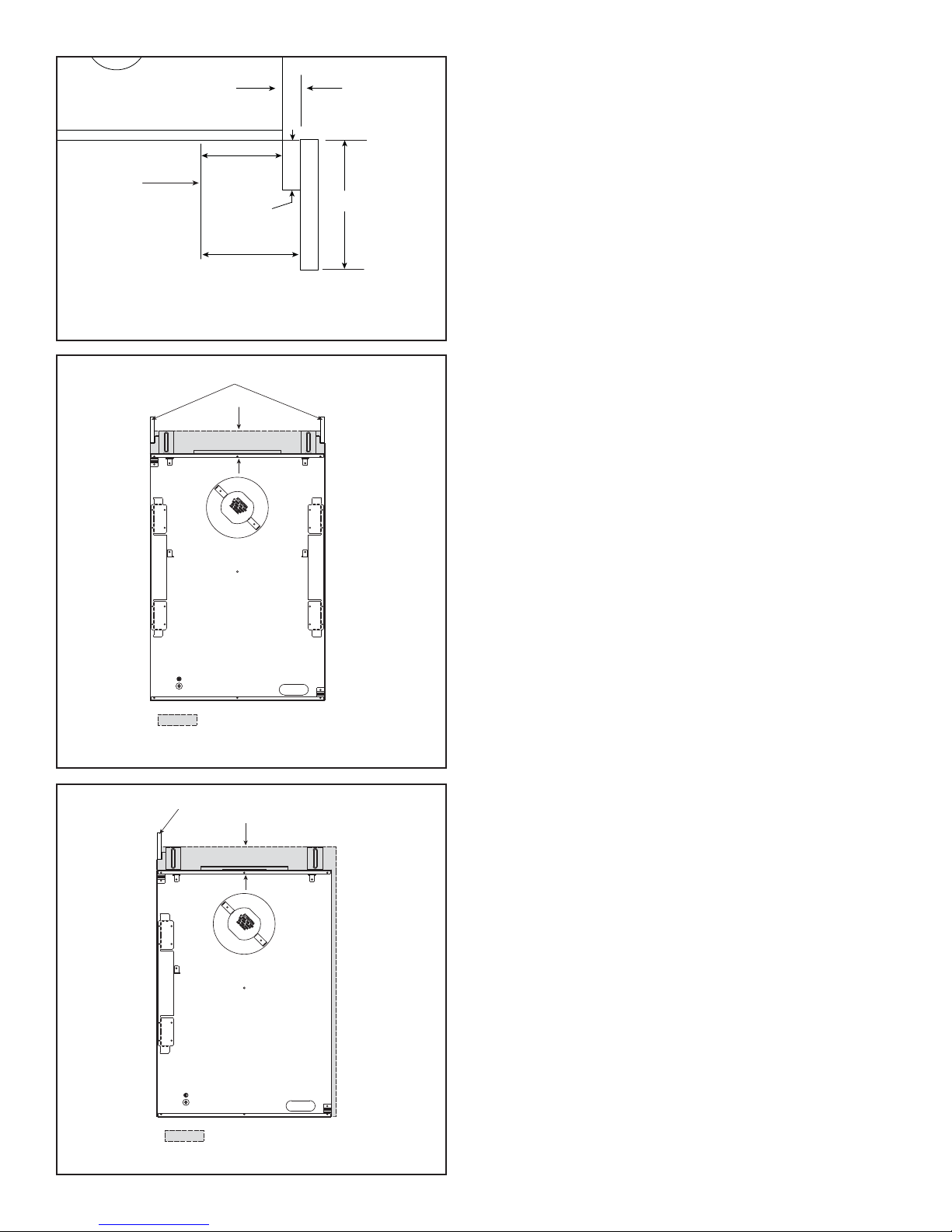
TOP VIEW
1/2 in.
Min.
FIREPLACE
OPENING
2-3/4
in. Min.
1 in.
Unlimited
Max.
3-1/4 in. Min.
Note: Clearance from opening to perpendicular wall.
Figure 5.9 Combustible Mantel Leg or Wall Projections
(Acceptable on both sides of opening)
SHEETROCK
3.5 in.
AIR SPACE REQUIRED
Figure 5.10 Non-Combustible Zone
(GDFL4136I, GDST4336I)
SHEETROCK
3.5 in.
AIR SPACE REQUIRED
Figure 5.11 Non-Combustible Zone (GDCR4136I and GDCL4136I)
Heatilator • GDST4336I, GDFL4136I, GDCR4136I, GDCL4136I • 2129-900 Rev. W • 12/1522
6
6
Termination Locations
A. Vent Termination Minimum Clearances
WARNING
Fire Risk.
Maintain vent clearance to combustibles as
specifi ed.
• DO NOT pack air space with insulation or other
materials.
Failure to keep insulation or other materials away
from vent pipe may cause overheating and fi re.
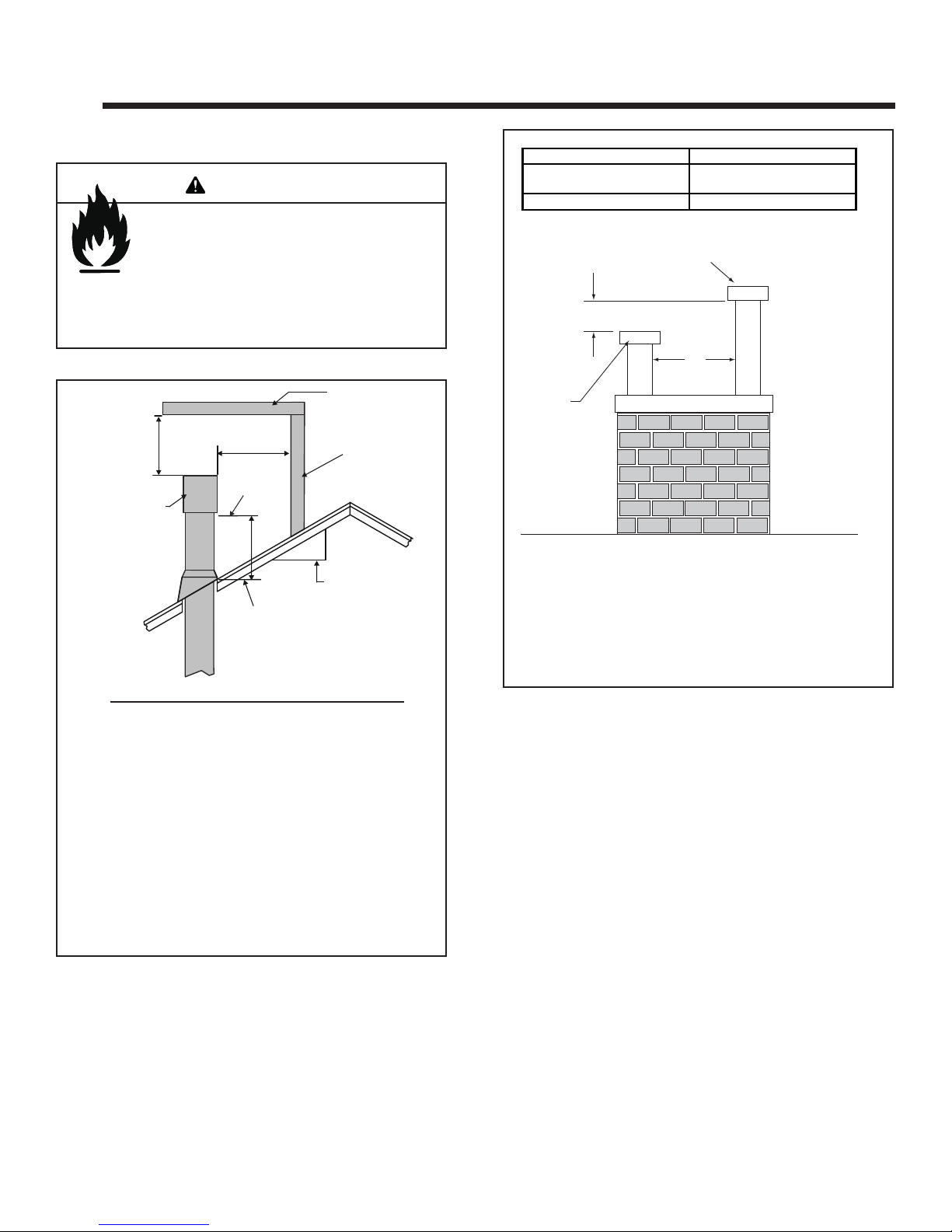
6 in. (minimum) up to 20 in.
AB
152 mm/508 mm
20 in. and over 0 in. minimum
Gas, Wood or Fuel Oil
Termination Cap
B
A *
18 in. minimum
457 mm
HORIZONTAL
OVERHANG
2 FT.
MIN.
GAS DIRECT VENT
TERMINATION CAP
Roof Pitch H (Min.) Ft.
Flat to 6/12...........................................................1.0*
Over 6/12 to 7/12 .................................................1.25*
Over 7/12 to 8/12 .................................................1.5*
Over 8/12 to 9/12 .................................................2.0*
Over 9/12 to 10/12 ...............................................2.5*
Over 10/12 to 11/12 .............................................3.25
Over 11/12 to 12/12 .............................................4.0
Over 12/12 to 14/12 .............................................5.0
Over 14/12 to 16/12 .............................................6.0
Over 16/12 to 18/12 .............................................7.0
Over 18/12 to 20/12 .............................................7.5
Over 20/12 to 21/12 .............................................8.0
* 3 foot minimum in snow regions
Figure 6.1 Minimum Height From Roof To Lowest Discharge
Opening
20 INCHES MIN.
LOWEST
DISCHARGE
OPENING
H (MIN.) - MINIMUM HEIGHT FROM ROOF
TO LOWEST DISCHARGE OPENING
X
12
ROOF PITCH
VERTICAL
WALL
IS X/ 12
Gas
Termination
Cap **
If using decorative cap cover(s), this distance may need to be
*
increased. Refer to the installation instructions supplied with the
decorative cap cover.
In a staggered installation with both gas and wood or fuel oil
**
terminations, the wood or fuel oil termination cap must be
higher than the gas termination cap.
Figure 6.2 Staggered Termination Caps
Heatilator • GDST4336I, GDFL4136I, GDCR4136I, GDCL4136I • 2129-900 Rev. W • 12/15
23
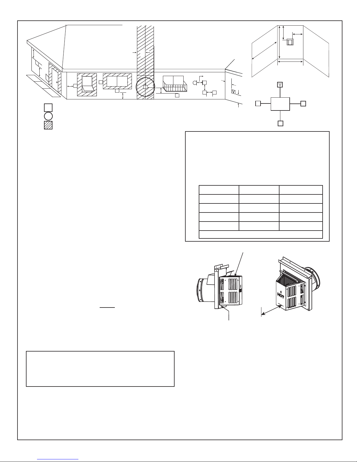
C
V
B
J
V
V
= VENT TERMINAL
X
= AIR SUPPLY INLET
B
D
V
V
V
A
F
B
G
M
= AREA WHERE TERMINAL IS NOT PERMITTED
A = 12 inches.................clearances above grade, veranda,
porch, deck or balcony
12 inches.................clearance to window or door that may
B =
be opened, or to permanently closed
window
C = 18 inches.................clearance below unventilated soffi t
18 inches.................clearance below ventilated soffi t
30 inches .................clearance below vinyl soffits and
electrical service
D = 6 inches...................clearance to outside corner
E = 6 inches...................clearance to inside corner
F = 3 ft. (Canada) ..........not to be installed above a gas me-
ter/regulator assembly within 3 feet
horizontally from the center-line of the
regulator
G = 3 ft ...........................clearance to gas service regulator
vent outlet
H = 9 inches (U.S.A)
12 inches (Canada). clearance to non-mechanical (unpow-
ered) air supply inlet, combustion air
inlet or direct-vent termination
i = 3 ft. (U.S.A.)
6 ft. (Canada) ...........clearance to a mechanical (powered)
air supply inlet
All mechanical air intakes within 10 feet of a termination cap
must be a minimum of 3 feet below termination.
J = 7 ft. ......................... On public property: clearance above
paved sidewalk or a paved driveway.
A vent shall not terminate directly above a sidewalk or paved
driveway which is located between two single family dwellings
and serves both dwellings.
K = 6 inches................. clearance from sides of electrical
service
L = 12 inches................ clearance above electrical service
Location of the vent termination must not interfere with access to the
electrical service.
M = 18 inches .................... clearance under veranda, porch, deck,
balcony or overhang
42 inches ................vinyl or composite overhang
Permitted when veranda, porch, deck or balcony is fully open
on a minimum of 2 sides beneath the fl oor.
Figure 6.3 Minimum Clearances for Termination
O
N
P
R
Q
H or i
V
X
H
V
V
H
E
V
V
A
V
K
V
L
Electrical
Service
C
V
K
V
Covered Alcove Applications
(Spaces open only on one side and with an overhang)
N = 6 inches ........... non-vinyl sidewalls
12 inches ......... vinyl sidewalls
O = 18 inches ......... non-vinyl soffi t and overhang
42 inches ......... vinyl soffi t and overhang
P = 8 ft.
Q
MIN
1 cap 3 feet 2 x Q
2 caps 6 feet 1 x Q
3 caps 9 feet 2/3 x Q
4 caps 12 feet 1/2 x Q
Q
= # termination caps x 3 R
MIN
Measure vertical clearances from this surface.
Measure horizontal clearances from this surface.
= (2 / # termination caps) x Q
MAX
CLEARANCE = 6 IN.
R
MAX
ACTUAL
ACTUAL
ACTUAL
ACTUAL
ACTUAL
CAUTION! Risk of Burns! Termination caps are HOT,
consider proximity to doors, traffi c areas or where people
may pass or gather (sidewalk, deck, patio, etc.). Listed cap
shields available. Contact your dealer.
• Local codes or regulations may require different
clearances.
• Vent system termination is NOT permitted in screened
porches.
• Vent system termination is permitted in porch areas with
two or more sides open.
• Hearth & Home Technologies assumes no responsibility
for the improper performance of the appliance when the
venting system does not meet these requirements.
• Vinyl protection kits are suggested for use with vinyl siding.
Heatilator • GDST4336I, GDFL4136I, GDCR4136I, GDCL4136I • 2129-900 Rev. W • 12/1524
7
7
Vent Information and Diagrams
A. Approved Pipe
This appliance is approved for use with Hearth & Home
Technologies a DVP or SLP venting system. Refer to
Section 16.B for vent component information.
DO NOT mix pipe, fi ttings or joining methods from differ-
ent manufacturers.
The pipe is tested to be run inside an enclosed wall.
There is no requirement for inspection openings at each
joint within the wall.
WARNING! Risk of Fire or Asphyxiation. This appliance requires a separate vent. DO NOT vent to a pipe
serving a separate solid fuel burning appliance.
Vertical
12 in.
8-1/2 in.
8-1/2 in.
B. Vent Table Key
The abbreviations listed in this vent table key are used in
the vent diagrams.
Symbol Description
First section (closest to appliance) of vertical length
V
1
Second section of vertical length
V
2
H
H
First section (closest to appliance) of horizontal length
1
Subsequent sections of horizontal length
2
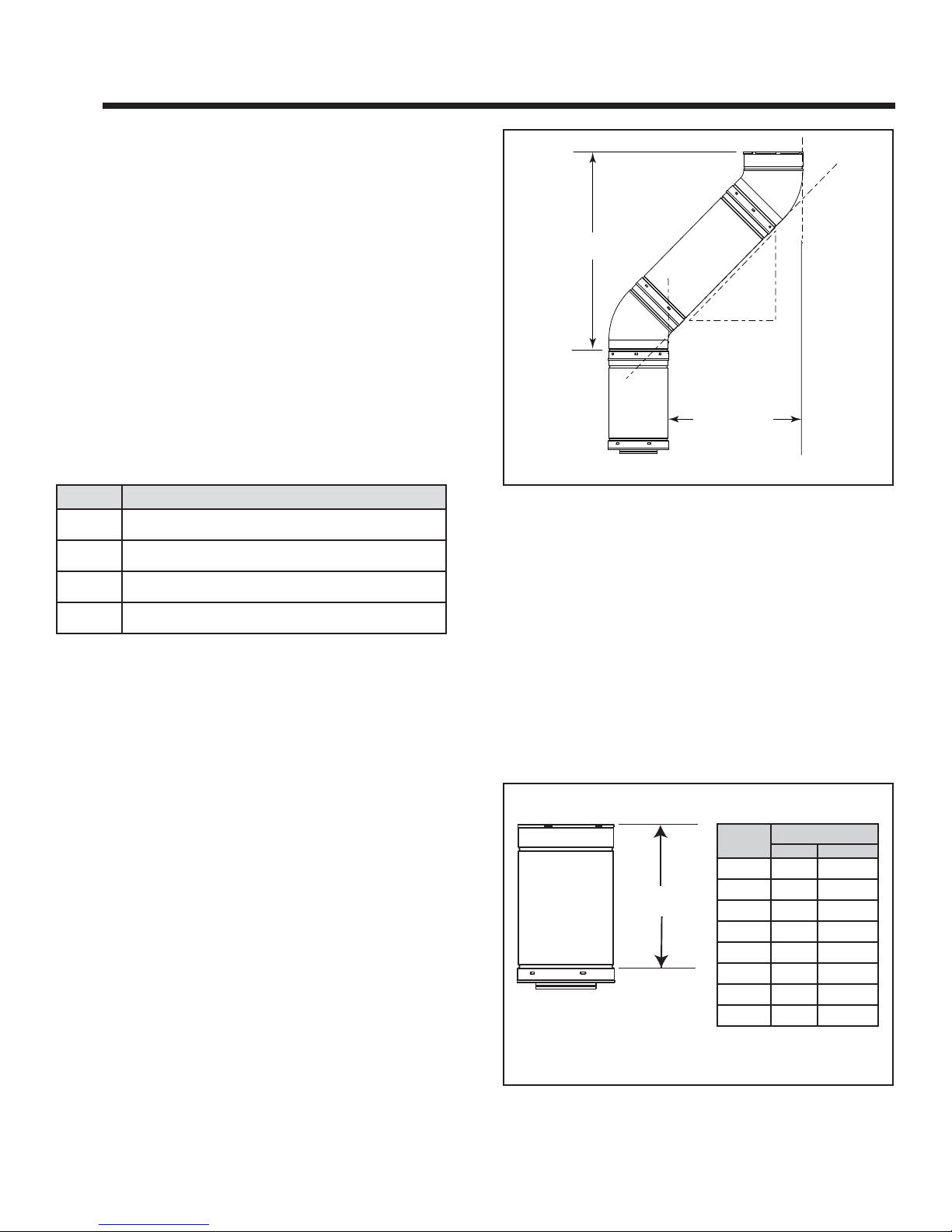
C. Use of Elbows
Diagonal runs have both vertical and horizontal vent aspects when calculating the effects. Use the rise for the
vertical aspect and the run for the horizontal aspect (see
Figure 7.1).
Two 45º elbows may be used in place of one 90º elbow.
On 45º runs, one foot of diagonal is equal to 8-1/2 in. (216
mm) horizontal run and 8-1/2 in. (216 mm) vertical run. A
length of straight pipe is allowed between two 45º elbows
(see Figure 7.1).
Horizontal
Figure 7.1
D. Measuring Standards
Vertical and horizontal measurements listed in the vent
diagrams were made using the following standards.
• Pipe measurements are shown using the effective length
of pipe (see Figure 7.2).
• Horizontal terminations are measured to the outside
mounting surface (fl ange of termination cap) (see Figure
6.3).
• Vertical terminations are measured to bottom of
termination cap.
• Horizontal pipe installed level with no rise.
Effective Length
Inches Millimeters
Effective
Height/Length
Pipe
DVP4 4 102
DVP6 6 152
DVP12 12 305
DVP24 24 610
DVP36 36 914
DVP48 48 1219
DVP6A 3 to 6 76 to 152
DVP12A 3 to 12 76 to 305
Heatilator • GDST4336I, GDFL4136I, GDCR4136I, GDCL4136I • 2129-900 Rev. W • 12/15
Figure 7.2 DVP Pipe Effective Length
25
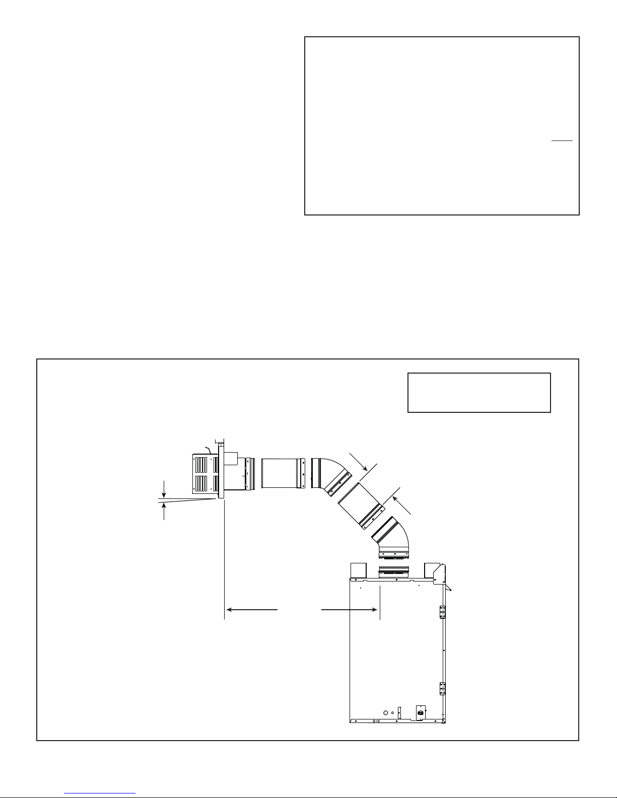
E. Vent Diagrams
General Rules:
• A maximum of three 90° elbows (or six 45° elbows) may
be used in any vent confi guration. Some elbows may be
installed horizontally. See Figure 7.6.
• Elbows may be placed back to back anywhere in the
system as long as the fi rst 90° elbow is a starter elbow
except as shown in Figure 7.3.
• When penetrating a combustible wall, a wall shield
fi restop must be installed.
• When penetrating a combustible ceiling, a ceiling fi restop
must be installed.
• Horizontal runs of vent do not require vertical rise;
horizontal runs may be level.
• Horizontal termination cap should have a 1/4 inch
downward slant to allow any moisture in cap to be
released. See Figure 7.3.
Note: The Multi-Sided series fi replaces can adapt
to SLP series vent pipe, if desired.
When venting off the top of the unit, attach a DVP-2SL adapter to
the appliance starting collar, immediately followed by a minimum
48 inch vertical section of SLP series vent pipe.
After the 48 inch vertical section, the venting table rules
must be followed. The fi rst 48 inch vertical section is NOT
counted as part of the vertical components in the table. It is
still counted as part of the overall maximum run. All venting
table rules for the vent run must still be followed.
Example:
SLP pipe 7 ft. min. vertical = 11 ft. max. horizontal
DVP pipe 3 ft. min. vertical = 11 ft. max. horizontal
Top Vent—Horizontal Termination—Two 45° Elbows
Installation requirements to replace the fi rst 90° elbow with two 45° elbows:
1/4 in. max.
(6 mm)
16 ft max.
(4.87 m)
Note: Reference Figure 7.14 for
special instructions for use of 45º
elbow on rear vent appliances.
4 ft min.
(1.22 m)
Figure 7.3
Heatilator • GDST4336I, GDFL4136I, GDCR4136I, GDCL4136I • 2129-900 Rev. W • 12/1526
 Loading...