

Heatilator GDCH60, GDST60, GDFL60, GDCR60, GDCL60 Owner's Manual

Models:
GDCH60 Series
GDST60 Series
GDFL60 Series
GDCR60 Series
GDCL60 Series
Direct Vent Gas Appliance
Owner’s Manual
Installation and Operation
GDCH60 shown
CAUTION
DO NOT DISCARD THIS MANUAL
•
• Important operating and
maintenance instructions
included.
Read, understand and follow
these instructions for safe
installation and operation.
WARNING
If the information in these instructions is not followed exactly, a
fi re may result causing property
damage, personal injury, or death.
• Do not store or use gasoline or other fl am-
mable vapors and liquids in the vicinity of
this or any other appliance.
• What to do if you smell gas:
- Do not try to light any appliance.
- Do not touch any electrical switch. Do not
use any phone in your building.
- Immediately call your gas supplier from
a neighbor’s phone. Follow the gas
supplier’s instructions.
- If you cannot reach your gas supplier, call
the fi re department.
• Installation and service must be performed
by a qualifi ed installer, service agency, or
the gas supplier.
DO NOT
DISCARD
•
Leave this manual with
party responsible for
use and operation.
WARNING
HOT SURFACES!
Glass and other surfaces are hot during
operation and cool down.
Hot glass will cause burns.
• Do not touch glass until it is cooled
• NEVER allow children to touch glass
• Keep children away
• CAREFULLY SUPERVISE children in same room as
appliance.
• Alert children and adults to hazards of high
temperatures.
High temperatures may ignite clothing or other
fl ammable materials.
• Keep clothing, furniture, draperies and other combustibles
away.
This appliance has been supplied with an integral
barrier to prevent direct contact with the fi xed glass
panel. Do NOT operate the appliance with the barrier
removed.
Contact your dealer or Hearth & Home Technologies if the
barrier is not present or help is needed to properly install one.
¨
This appliance may be installed as an OEM installation in manufactured
home (USA only) or mobile home and must be installed in accordance
with the manufacturer’s instructions and the manufactured home
construction and safety standard, Title 24 CFR, Part 3280 or Standard
for Installation in Mobile Homes, CAN/CSA Z240MH.
This appliance is only for use with the type(s) of gas indicated on the
rating plate.
Heatilator • Caliber Multi-Sided Direct Vent • 4002-079 Rev K • 11/07 1
In the Commonwealth of Massachusetts installation must
be performed by a licensed plumber or gas fi tter;
See Table of Contents for location of additional
Commonwealth of Massachusetts requirements.
Installation and service of this appliance should be performed
by qualifi ed personnel. Hearth & Home Technologies suggests
NFI certifi ed or factory-trained professionals, or technicians
supervised by an NFI certifi ed professional.
Read this manual before installing or operating this appliance.
Please retain this owner’s manual for future reference.
Congratulations
Congratulations on selecting a Heatilator gas appliance—an
elegant and clean alternative to wood burning appliances.
The Heatilator gas appliance you have selected is designed
to provide the utmost in safety, reliability, and effi ciency.
As the owner of a new appliance, you’ll want to read and
carefully follow all of the instructions contained in this owner’s
The information contained in this owner’s manual, unless
noted otherwise, applies to all models and gas control
systems.
Your new Heatilator gas appliance will give you years of
durable use and trouble-free enjoyment. Welcome to the
Heatilator family of appliance products!
manual. Pay special attention to all cautions and warnings.
This owner’s manual should be retained for future reference.
We suggest you keep it with your other important documents
and product manuals.
We recommend that you record the following pertinent
Homeowner Reference Information
information about your appliance:
Model Name: Date purchased/installed:
Serial Number: Location on appliance:
Dealership purchased from: Dealer phone:
Notes:
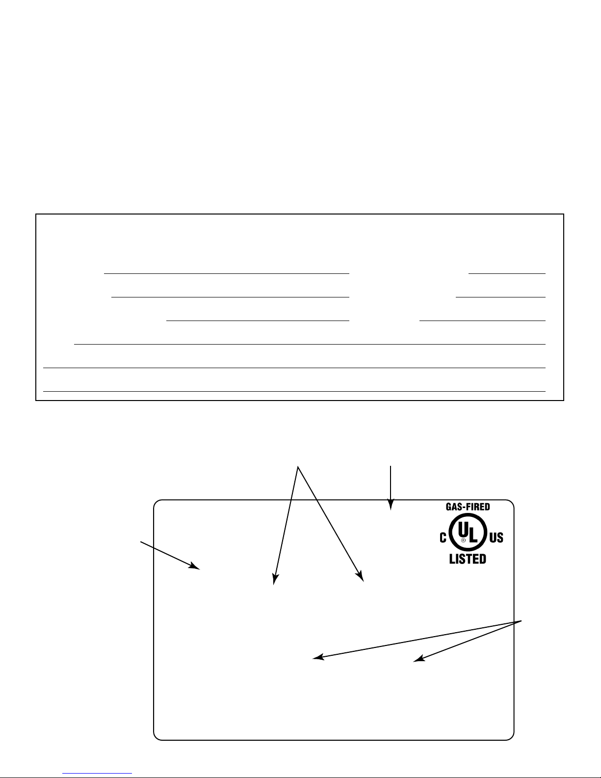
Listing Label Information/Location
The model information regarding your specifi c appliance can be found on the rating plate located in the control area of the
appliance.
Serial #
XXXXXXXXX
XXXX
CERTIFIED
FOR CANADA
CERTIFIÉ POUR LE
CANADA
Orifice
Size
Model #
Gas Type
Hearth & Home Technologies Inc
1915 W. Saunders Street
Mt. Pleasant, IA 52641
ANSI Standard
MODEL MFG. DATE
MODÈLE DATE DE FAB.
GAS TYPE/TYPE DE GAZ NATURAL/NATUREL PROPANE
ALTITUDE 0-2000 2000-4000 FT/PI 0-2000 2000-4000 FT/PI
MAX INPUT/DÉBIT XX,XXX XX,XXX BTUH XX,XXX XX,XXX BTUH
MIN INPUT/DÉBIT XX,XXX XX,XXX BTUH XX,XXX XX,XXX BTUH
MANIFOLD PRESSURE/PRESSION TUBULAIRE
MAX. XX IN. W.C./C. D'EAU XX IN. W.C./C. D'EAU
MIN. XX IN. W.C./C. D'EAU XX IN. W.C./C. D'EAU
MIN. INLET PRESS. XX IN. W.C./C. D'EAU 1XX IN. W.C./C. D'EAU
FOR THE PURPOSE OF INPUT ADJUSTMENT
PRESS. MIN. D'ALIMENTATION
ORIFICE SIZE
DIAM. DE L'INJECTEUR XX/XX DIA. in./mm XX/XX DIA. in./mm
XXXXXX
SERIAL
NO. DE SÉRIE
LESS THAN/MOINS DE 3 AMPÈRES., 115V., 60 Hz
DO NOT REMOVE OR COVER THIS LABEL.
VENTED GAS FIREPLACE - NOT FOR USE WITH SOLID FUEL.
FOYER À GAZ À ÉVACUATION - NE DOIT PAS ÊTRE UTILISÉ
AVEC UN COMBUSTIBLE SOLIDE.
2 Heatilator • Caliber Multi-Sided Direct Vent • 4002-079 Rev K • 11/07

Table of Contents
1 Listing and Code Approvals 4
A. Appliance Certifi cation . . . . . . . . . . . . . . . . . . . . . . . . . 4
B. Glass Specifi cations . . . . . . . . . . . . . . . . . . . . . . . . . . 4
C. BTU Specifi cations . . . . . . . . . . . . . . . . . . . . . . . . . . . 4
D. High Altitude Installations . . . . . . . . . . . . . . . . . . . . . .4
E. Non-Combustible Materials . . . . . . . . . . . . . . . . . . . . .4
F. Combustible Materials . . . . . . . . . . . . . . . . . . . . . . . . . 4
G. Requirements for the
Commonwealth of Massachusetts. . . . . . . . . . . . . . . . 5
2 Getting Started 6
A. Design and Installation Considerations . . . . . . . . . . . .6
B. Tools and Supplies Needed . . . . . . . . . . . . . . . . . . . . . 6
C. Inspect the Appliance and Components . . . . . . . . . . . 6
3 Framing and Clearances 7
A. Select Appliance Location . . . . . . . . . . . . . . . . . . . . . .7
B. Construct the Appliance Chase . . . . . . . . . . . . . . . . . . 9
C. Mantel Projections . . . . . . . . . . . . . . . . . . . . . . . . . . . . 9
D. Clearances . . . . . . . . . . . . . . . . . . . . . . . . . . . . . . . .10
4 Termination Locations 11
A. Vent Termination Minimum Clearances . . . . . . . . . . . 11
5 Vent Information and Diagrams 13
A. Vent Table Key . . . . . . . . . . . . . . . . . . . . . . . . . . . . . . 13
B. Use of Elbows . . . . . . . . . . . . . . . . . . . . . . . . . . . . . . 13
C. Measuring Standards. . . . . . . . . . . . . . . . . . . . . . . . . 13
D. Vent Diagrams . . . . . . . . . . . . . . . . . . . . . . . . . . . . . . 14
6 Vent Clearances and Framing 23
A. Pipe Clearances to Combustibles . . . . . . . . . . . . . . . 23
B. Wall Penetration Framing . . . . . . . . . . . . . . . . . . . . .23
Install the Ceiling Firestop . . . . . . . . . . . . 24
C.
D. Install Attic Insulation Shield . . . . . . . . . . . . . . . . . . . 25
7 Appliance Preparation 26
A. Appliance Placement . . . . . . . . . . . . . . . . . . . . . . . . . 26
B. Secure the Appliance. . . . . . . . . . . . . . . . . . . . . . . . . 26
C. Convert from Top Vent to Rear Vent . . . . . . . . . . . . . 26
D. Securing and Leveling the Appliance . . . . . . . . . . . .28
8 Installing Vent Pipe 29
A. Assemble Vent Sections . . . . . . . . . . . . . . . . . . . . . . 29
B. Disassemble Vent Sections . . . . . . . . . . . . . . . . . . . . 31
C. Install the Heat Shield and
Horizontal Termination Cap . . . . . . . . . . . . . . . . . . . . 32
D. Install Roof Flashing and Vertical Termination Cap . . 33
E. Assemble and Install Storm Collar . . . . . . . . . . . . . . 34
9 Gas Information 35
A. Fuel Conversion . . . . . . . . . . . . . . . . . . . . . . . . . . . . 35
B. Gas Pressure. . . . . . . . . . . . . . . . . . . . . . . . . . . . . . . 35
C. Gas Connection . . . . . . . . . . . . . . . . . . . . . . . . . . . . . 35
D. High Altitude Installations . . . . . . . . . . . . . . . . . . . . .36
10 Electrical Information 37
A. Recommendation for Wire . . . . . . . . . . . . . . . . . . . . . 37
B. Connecting to the Appliance . . . . . . . . . . . . . . . . . . . 37
C. Intellifi re Ignition System Wiring . . . . . . . . . . . . . . . .37
D. Standing Pilot Ignition System Wiring . . . . . . . . . . . . 38
E. Junction Box Installation . . . . . . . . . . . . . . . . . . . . . . 39
F. Wall Switch Wiring . . . . . . . . . . . . . . . . . . . . . . . . . . . 39
G. Install the Light Kit (optional) . . . . . . . . . . . . . . . . . . .39
11 Finishing 41
A. Mantel Projections . . . . . . . . . . . . . . . . . . . . . . . . . . . 41
B. Facing Material . . . . . . . . . . . . . . . . . . . . . . . . . . . . .41
12 Appliance Setup 42
A. Remove Glass Assembly. . . . . . . . . . . . . . . . . . . . . . 42
B. Remove the Shipping Materials. . . . . . . . . . . . . . . . . 42
C. Clean the Appliance. . . . . . . . . . . . . . . . . . . . . . . . . .42
D. Accessories . . . . . . . . . . . . . . . . . . . . . . . . . . . . . . . . 42
E. White Rock, Lava Rock,
Vermiculite & Rockwool Placement . . . . . . . . . . . . . . . 42
F. Log Assembly . . . . . . . . . . . . . . . . . . . . . . . . . . . . . . 43
G. Glass Panel Assembly . . . . . . . . . . . . . . . . . . . . . . . . 43
H. Firescreen . . . . . . . . . . . . . . . . . . . . . . . . . . . . . . . . . 43
I. Grilles and Trim . . . . . . . . . . . . . . . . . . . . . . . . . . . . . 44
J. Hood . . . . . . . . . . . . . . . . . . . . . . . . . . . . . . . . . . . . . 44
K. Air Shutter Setting . . . . . . . . . . . . . . . . . . . . . . . . . . . 44
13 Operating Instructions 45
A. Before Lighting Appliance . . . . . . . . . . . . . . . . . . . . . 45
B. Lighting the Appliance . . . . . . . . . . . . . . . . . . . . . . . .46
C. After the Appliance is Lit . . . . . . . . . . . . . . . . . . . . . . 48
D. Frequently Asked Questions . . . . . . . . . . . . . . . . . . .48
14 Troubleshooting 49
A. Standing Pilot Ignition System . . . . . . . . . . . . . . . . . . 49
B. Intellifi re Ignition System . . . . . . . . . . . . . . . . . . . . . . 51
15 Maintaining and Servicing the Appliance 53
16 Reference Materials 55
A. Appliance Dimension Diagram . . . . . . . . . . . . . . . . .55
B. Vent Components Diagrams . . . . . . . . . . . . . . . . . . . 57
C. Service Parts List. . . . . . . . . . . . . . . . . . . . . . . . . . . . 64
D. Optional Components . . . . . . . . . . . . . . . . . . . . . . . . 84
E. Limited Lifetime Warranty . . . . . . . . . . . . . . . . . . . . . 87
F. Contact Information . . . . . . . . . . . . . . . . . . . . . . . . . . 88
Note: An arrow (¨) found in the text signifi es change in
content.
Heatilator • Caliber Multi-Sided Direct Vent • 4002-079 Rev K • 11/07 3
1
Listing and Code Approvals
1
A. Appliance Certifi cation
MODELS: GDCH60, GDST60, GDFL60, GDCR60,
GDCL60
LABORATORY: Underwriters Laboratories, Inc. (UL)
TYPE: Direct Vent Gas Appliance
STANDARD: ANSI Z21.50b-2005/•CSA2.22b-2005
/UL307B
This product is listed to ANSI standards for “Vented Gas
Fireplaces” and applicable sections of “Gas Burning Heating Appliances for Manufactured Homes and Recreational
Vehicles”, and “Gas Fired Appliances for Use at High Altitudes”.
NOT INTENDED FOR USE AS A PRIMARY HEAT
SOURCE. This appliance is tested and approved as either
supplemental room heat or as a decorative appliance. It
should not be factored as primary heat in residential heating
calculations.
B. Glass Specifi cations
Hearth & Home Technologies appliances manufactured with
tempered glass may be installed in hazardous locations such
as bathtub enclosures as defi ned by the Consumer Product
Safety Commission (CPSC). The tempered glass has been
tested and certifi ed to the requirements of ANSI Z97.1 and
CPSC 16 CFR 1202 (Safety Glazing Certifi cation Council
SGCC# 1595 and 1597. Architectural Testing, Inc. Reports
02-31919.01 and 02-31917.01).
This statement is in compliance with CPSC 16 CFR Section
1201.5 “Certifi cation and labeling requirements” which refers
to 15 U.S. Code (USC) 2063 stating “…Such certifi cate shall
accompany the product or shall otherwise be furnished to
any distributor or retailer to whom the product is delivered.”
Some local building codes require the use of tempered glass
with permanent marking in such locations. Glass meeting
this requirement is available from the factory. Please contact
your dealer or distributor to order.
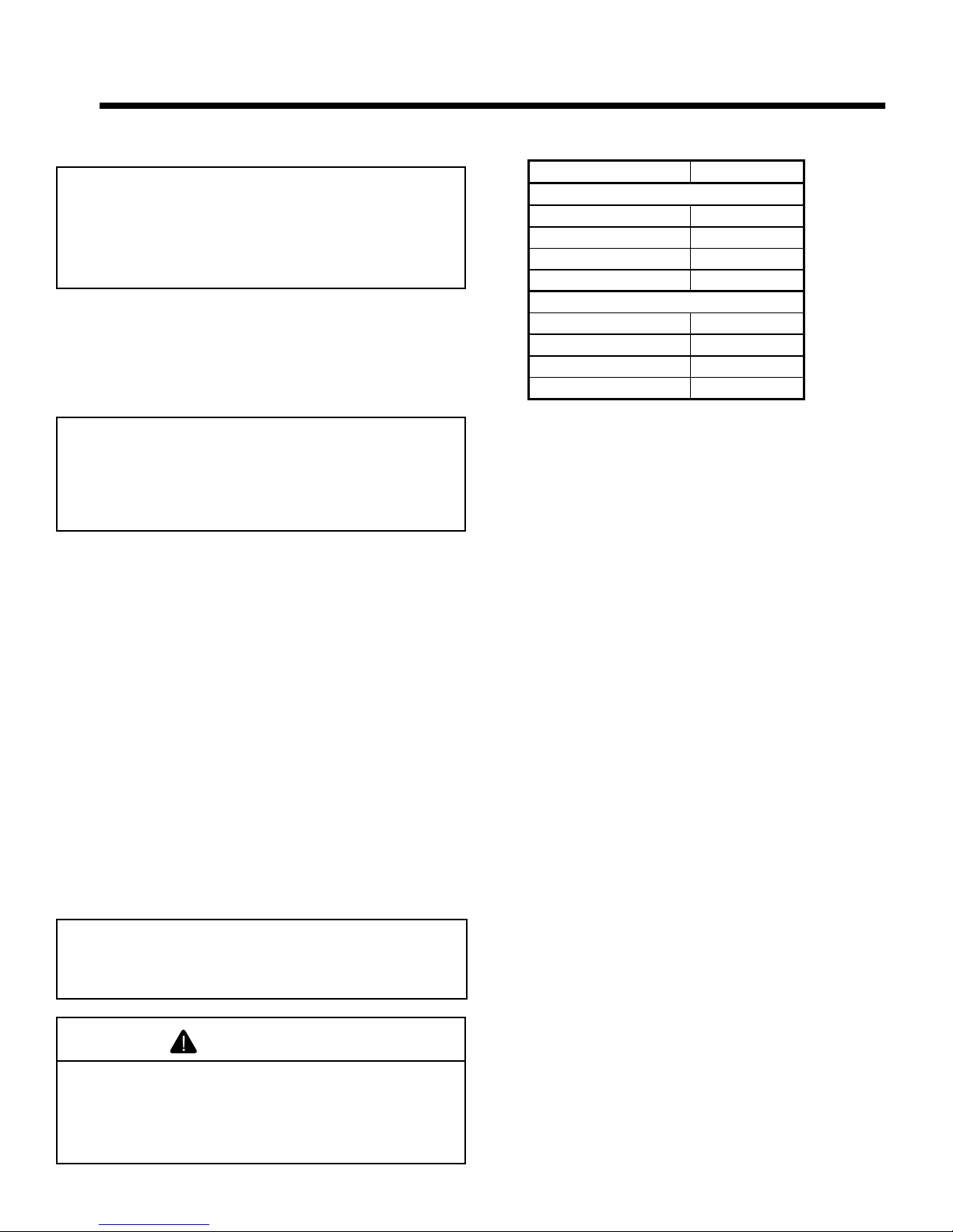
C. BTU Specifi cations
Caliber Multi-sided DV
Standing Pilot
Max/Min Input Rate (NG) 34,000/21,000
Orifi ce Size (NG) .115 in./2.92 mm
Max/Min Input Rate (LP) 30,000/21,000
Orifi ce Size (LP) .063 in./1.60 mm
IPI
Max/Min Input Rate (NG) 34,000/25,000
Orifi ce Size (NG) .115 in./2.92 mm
Max/Min Input Rate (LP) 30,000/22,000
Orifi ce Size (LP) .065 in./1.65 mm
D. High Altitude Installations
U.L. Listed gas appliances are tested and approved without
requiring changes for elevations from 0 to 2000 feet in the
U.S.A. and Canada.
When installing this appliance at an elevation above 2000 ft,
it may be necessary to decrease the input rating by changing the existing burner orifi ce to a smaller size. Input rate
should be reduced by 4% for each 1000 ft above a 2000 ft
elevation in the U.S.A., or 10% for elevations between 2000
and 4500 ft in Canada. If the heating value of the gas has
been reduced, these rules do not apply. To identify the proper orifi ce size, check with the local gas utility.
If installing this appliance at an elevation above 4500 ft (in
Canada), check with local authorities.
E. Non-Combustible Materials
Material which will not ignite and burn. Such materials are
those consisting entirely of steel, iron, brick, tile, concrete,
slate, glass or plasters, or any combination thereof.
Materials that are reported as passing ASTM E 136, Stan-
dard Test Method for Behavior of Materials in a Vertical
Tube Furnace at 750° C, shall be considered non-combus-
tible materials.
Note: This installation must conform with local codes. In the
absence of local codes you must comply with the National
Fuel Gas Code, ANSI Z223.1-latest edition in the U.S.A.
and the CAN/CGA B149 Installation Codes in Canada.
WARNING
Do NOT use this appliance if any part has been under
water. Immediately call a qualifi ed service technician
to inspect the appliance and to replace any part of the
control system and any gas control which has been
under water.
4 Heatilator • Caliber Multi-Sided Direct Vent • 4002-079 Rev K • 11/07
F. Combustible Materials
Materials made of or surfaced with wood, compressed paper, plant fi bers, plastics, or other material that can ignite and
burn, whether fl ame proofed or not, or whether plastered or
unplastered shall be considered combustible materials.

NOTE: The following requirements reference various
Massachusetts and national codes not contained in this
document.
G. Requirements for the Commonwealth of
Massachusetts
G. Requirements for the Commonwealth of Massachusetts
For all side wall horizontally vented gas fueled equipment
installed in every dwelling, building or structure used in
whole or in part for residential purposes, including those
owned or operated by the Commonwealth and where the
side wall exhaust vent termination is less than seven (7)
feet above finished grade in the area of the venting, including but not limited to decks and porches, the following
requirements shall be satisfied:
Installation of Carbon Monoxide Detectors
At the time of installation of the side wall horizontal vented
gas fueled equipment, the installing plumber or gas fitter
shall observe that a hard wired carbon monoxide detector
with an alarm and battery back-up is installed on the floor
level where the gas equipment is to be installed. In addition,
the installing plumber or gas fitter shall observe that a
battery operated or hard wired carbon monoxide detector
with an alarm is installed on each additional level of the
dwelling, building or structure served by the side wall
horizontal vented gas fueled equipment. It shall be the
responsibility of the property owner to secure the services
of qualified licensed professionals for the installation of hard
wired carbon monoxide detectors.
In the event that the side wall horizontally vented gas fueled
equipment is installed in a crawl space or an attic, the hard
wired carbon monoxide detector with alarm and battery
back-up may be installed on the next adjacent floor level.
In the event that the requirements of this subdivision can
not be met at the time of completion of installation, the
owner shall have a period of thirty (30) days to comply with
the above requirements; provided, however, that during
said thirty (30) day period, a battery operated carbon monoxide detector with an alarm shall be installed.
Approved Carbon Monoxide Detectors
Each carbon monoxide detector as required in accordance
with the above provisions shall comply with NFPA 720 and
be ANSI/UL 2034 listed and IAS certified.
Signage
A metal or plastic identification plate shall be permanently
mounted to the exterior of the building at a minimum height
of eight (8) feet above grade directly in line with the exhaust
vent terminal for the horizontally vented gas fueled heating
appliance or equipment. The sign shall read, in print size no
less than one-half (1/2) inch in size, “GAS VENT
DIRECTLY BELOW. KEEP CLEAR OF ALL OBSTRUCTIONS”.
Inspection
The state or local gas inspector of the side wall horizontally
vented gas fueled equipment shall not approve the installation unless, upon inspection, the inspector observes carbon
monoxide detectors and signage installed in accordance
with the provisions of 248 CMR 5.08(2)(a)1 through 4.
Exemptions
The following equipment is exempt from 248 CMR
5.08(2)(a)1 through 4:
• The equipment listed in Chapter 10 entitled “Equipment
Not Required To Be Vented” in the most current edition
of NFPA 54 as adopted by the Board; and
• Product Approved side wall horizontally vented gas
fueled equipment installed in a room or structure sepa
rate from the dwelling, building or structure used in
whole or in part for residential purposes.
MANUFACTURER REQUIREMENTS
Gas Equipment Venting System Provided
When the manufacturer of Product Approved side wall
horizontally vented gas equipment provides a venting
system design or venting system components with the
equipment, the instructions provided by the manufacturer
for installation of the equipment and the venting system
shall include:
• Detailed instructions for the installation of the venting
system design or the venting system components; and
• A complete parts list for the venting system design or
venting system.
Gas Equipment Venting System NOT Provided
When the manufacturer of a Product Approved side wall
horizontally vented gas fueled equipment does not provide
the parts for venting the flue gases, but identifies “special
venting systems”, the following requirements shall be satisfied by the manufacturer:
• The referenced “special venting system” instructions
shall be included with the appliance or equipment
installation instructions; and
• The “special venting systems” shall be Product
Approved by the Board, and the instructions for that
system shall include a parts list and detailed installation
instructions.
A copy of all installation instructions for all Product
Approved side wall horizontally vented gas fueled equipment, all venting instructions, all parts lists for venting
instructions, and/or all venting design instructions shall
remain with the appliance or equipment at the completion of
the installation.
See Gas Connection section for additional Commonwealth of Massachusetts requirements.
-
Heatilator • Caliber Multi-Sided Direct Vent • 4002-079 Rev K • 11/07 5
2
Getting Started
2
A. Design and Installation Considerations
Heatilator direct vent gas appliances are designed to operate with all combustion air siphoned from outside of the
building and all exhaust gases expelled to the outside. No
additional outside air source is required.
CAUTION
Check building codes prior to installation.
• Installation MUST comply with local, regional,
state and national codes and regulations.
• Consult insurance carrier, local building, fire
offi cials or authorities having jurisdiction about
restrictions, installation inspection, and permits.
When planning an appliance installation, it’s necessary to
determine the following information before installing:
• Where the appliance is to be installed.
• The vent system confi guration to be used.
• Gas supply piping.
• Electrical wiring.
• Framing and fi nishing details.
• Whether optional accessories—devices such as a fan,
wall switch, or remote control—are desired.
C. Inspect the Appliance and Components
WARNING
Inspect appliance and components for
damage. Damaged parts may impair safe
operation.
• Do NOT install damaged components.
• Do NOT install incomplete components.
• Do NOT install substitute components.
Report damaged parts to dealer.
• Carefully remove the appliance and components from the
packaging.
• The vent system components and trim doors are shipped
in separate packages.
• The gas logs may be packaged separately and must be
fi eld installed.
• Report to your dealer any parts damaged in shipment,
particularly the condition of the glass.
• Read all of the instructions before starting the
installation. Follow these instructions carefully
during the installation to ensure maximum safety and
benefi t.
WARNING
Keep appliance dry.
• Mold or rust may cause
odors.
• Water may damage controls.
B. Tools and Supplies Needed
Before beginning the installation be sure that the following
tools and building supplies are available.
Reciprocating saw Framing material
Pliers Hi temp caulking material
Hammer Gloves
Phillips screwdriver Framing square
Flat blade screwdriver Electric drill and bits (1/4 in.)
Plumb line Safety glasses
Level Manometer
Voltmeter Tape measure
Non-corrosive leak check solution
1/2 - 3/4 in. length, #6 or #8 Self-drilling screws
One 1/4 in. female connection (for optional fan).
WARNING
Hearth & Home Technologies disclaims any
responsibility for, and the warranty will be
voided by, the following actions:
• Installation and use of any damaged appliance or
vent system component.
• Modifi cation of the appliance or vent system.
• Installation other than as instructed by Hearth & Home
Technologies.
• Improper positioning of the gas logs or the glass
door.
• Installation and/or use of any component part not
approved by Hearth & Home Technologies.
Any such action may cause a fi re hazard.
6 Heatilator • Caliber Multi-Sided Direct Vent • 4002-079 Rev K • 11/07
3
Framing and Clearances
3
Note:
• Illustrations refl ect typical installations and are FOR
DESIGN PURPOSES ONLY.
• Illustrations/diagrams are not drawn to scale.
• Actual installation may vary due to individual design
preference.
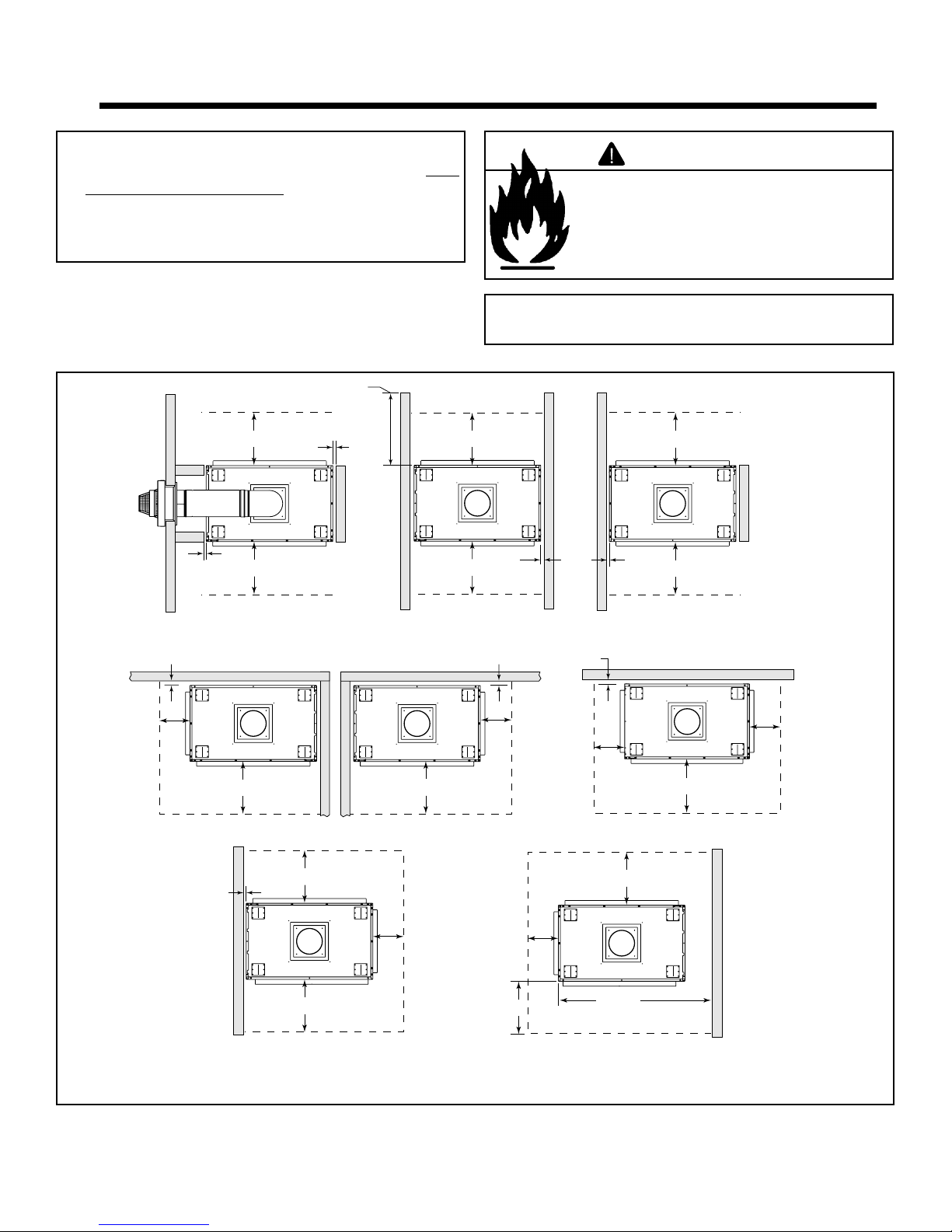
A. Select Appliance Location
When selecting a location for your appliance it is important to
consider the required clearances to walls (See Figure 3.1).
48 in. (219 mm)
maximum
WARNING
Fire Risk
Provide adequate clearance:
• Around air openings.
• For service access.
Locate appliance away from traffi c areas.
Note: For actual appliance dimensions refer to
Section 16.
12 in.
(305 mm)
1/2 in.
(13 mm)
1/2 in.
(13 mm)
1/2 in.
(13 mm)
36 in.
(914 mm)
(914 mm)
36 in.
(914 mm)
GDCL60
36 in.
(914 mm)
1/2 in.
(13 mm)
36 in.
36 in.
(914 mm)
GDCR60
12 in.
(305 mm)
(914 mm)
(914 mm)
GDST60
36 in.
36 in.
1/2 in.
(13 mm)
12 in.
(305 mm)
12 in.
(305 mm)
1/2 in.
(13 mm)
1/2 in.
(13 mm)
12 in.
(305 mm)
36 in.
(914 mm)
36 in.
(914 mm)
(914 mm)
36 in.
(914 mm)
36 in.
GDCH60
12 in.
(305 mm)
36 in.
(914 mm)
GDFL60
Figure 3.1 Appliance Locations
Heatilator • Caliber Multi-Sided Direct Vent • 4002-079 Rev K • 11/07 7
36 in.
(914 mm)
(using a Catalina Shelf and/or Marble Package)
45-1/4 in.
(1149 mm)
GDFL60
Appliance Locations for Catalina Marble & Shelf Package
If you plan to use a Catalina Marble and Shelf package, refer
to Figure 3.2 dimensions to determine appliance location.
Refer to the Catalina Installation Instructions included with
the kit for assembly and installation.
7 in.
(178 mm)
7 in.
(178 mm)
Marble Sizes:
Header - 26 in. x 8 in.
Side Headers - 45-1/2 in. x 8 in.
Legs - 33-1/2 in. x 7 in.
Thickness: 1/4 in.
Figure 3.2 Catalina Package Dimensions
34-1/2 in.
(876 mm)
50-1/2 in.
(1283 mm)
47-1/2 in.
(1206 mm)
8 Heatilator • Caliber Multi-Sided Direct Vent • 4002-079 Rev K • 11/07
B. Construct the Appliance Chase
A chase is a vertical boxlike structure built to enclose the gas
appliance and/or its vent system. Vertical vents that run on
the outside of a building may be, but are not required to be,
installed inside a chase.
Construction of the chase may vary with the type of building. These instructions are not substitutes for the requirements of local building codes. Local building codes MUST
be checked.
Chases should be constructed in the manner of all outside
walls of the home to prevent cold air drafting problems. The
chase should not break the outside building envelope in any
manner.
Walls, ceiling, base plate and cantilever fl oor of the chase
should be insulated. Vapor and air infi ltration barriers should
be installed in the chase as per regional codes for the rest
of the home. Additionally, in regions where cold air infi ltar-
tion may be an issue, the inside surfaces be sheetrocked
and taped (or use of an equivalent method) for maximum air
tightness.
To further prevent drafts, the ceiling fi restops should be
caulked with high temperature caulk to seal gaps. Gas line
holes and other openings should be caulked with high temperature caulk or stuffed with unfaced insulation. If the appliance is being installed on a cement slab, a layer of plywood
be placed underneath to prevent conducting cold up into the
room.
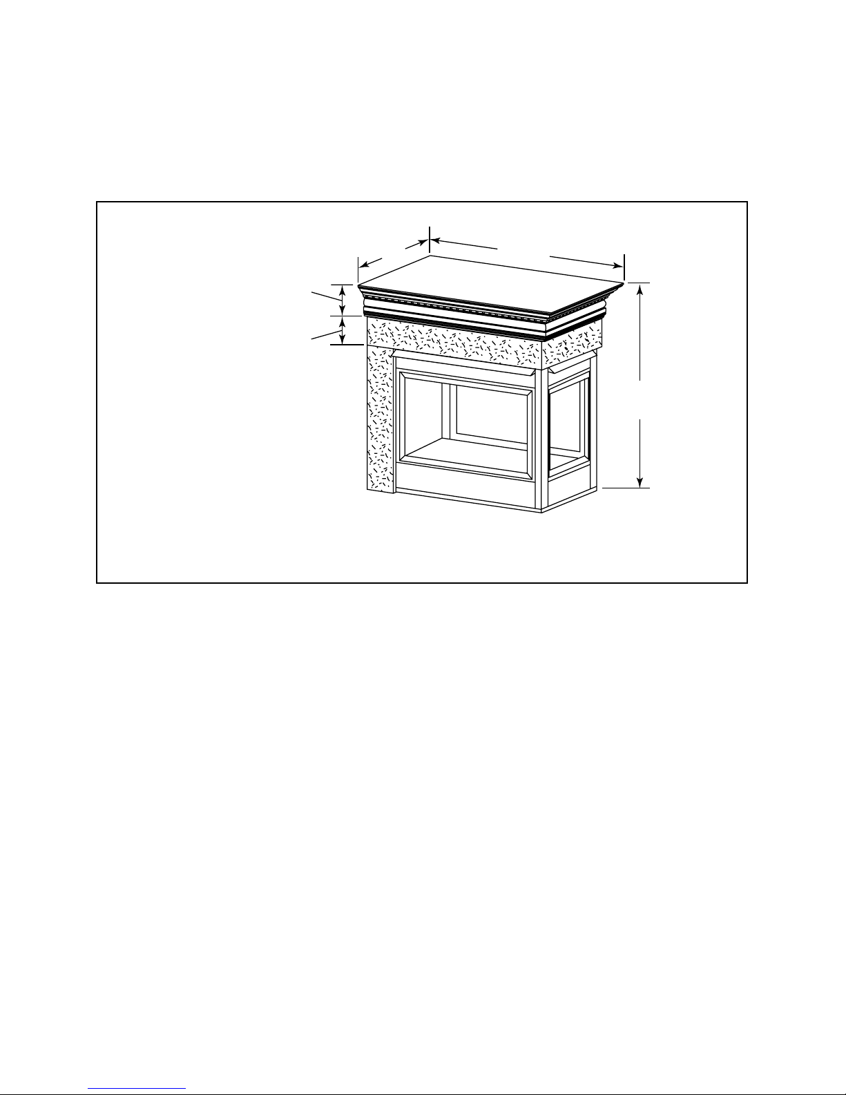
C. Mantel Projections
34-3/8 in. minimum
to ceiling
18
17
16
15
14
13
12
1-11
6-1/4
5-1/2
4-3/4
Measured from top of hood (in inches)
Figure 3.2 Clearances to Mantels or Other Combustibles Above
Appliance
Top o f
Appliance
8-1/2
7-3/4
7
10
9-1/4
Drywall
WARNING
Fire Risk
Odor Risk
• Install appliance on hard metal or wood
surfaces extending full width and depth
of appliance.
• Do NOT install appliance directly on
carpeting, vinyl, tile or any combustible
material other than wood.
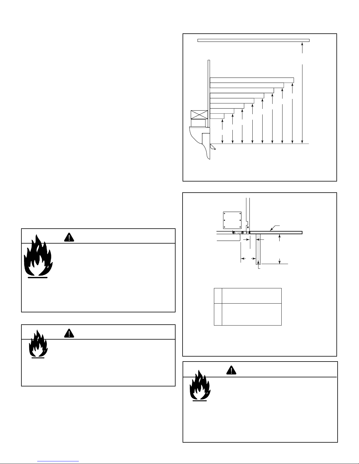
WARNING
Fire Risk
• Construct chase to all clearance
specifi cations in manual.
• Locate and install appliance to all
clearance specifi cations in manual.
A
B
Perpendicular Wall
0 in. min.
A
to perpendicular wall
2 in. (51 mm) min.
B
from fireplace opening
to perpendicular wall
Figure 3.3 Clearances to Mantel Legs or Wall Projections (Accept-
¨
able on both sides of opening)
48 in.
(1219 mm)
max.
Mantel Leg or
WARNING
Fire Risk
• Comply with all minimum clearances to
combustibles as specifi ed.
• Framing or fi nishing material used on the front of, or
in front of, the appliance closer than the minimums
listed, must be constructed entirely of noncombustible
materials (i.e., steel studs, concrete board, etc.).
Failure to comply may cause fi re.
Heatilator • Caliber Multi-Sided Direct Vent • 4002-079 Rev K • 11/07 9
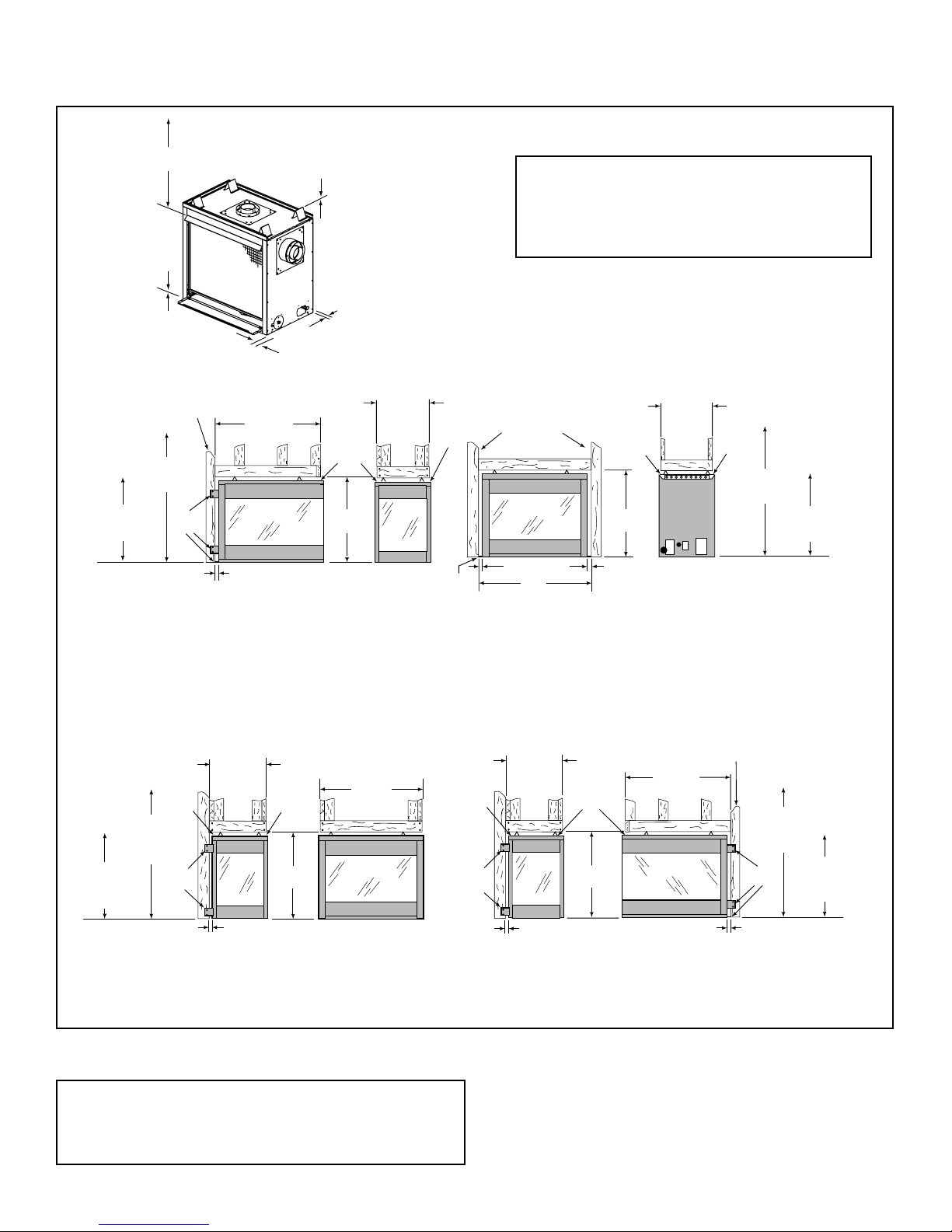
D. Clearances
34-3/8 in. (762 mm)
to ceiling
0 in.
TO FLOOR
Long side of
framing to front.
47 in. (1194 mm)
min. WINDOW
PLACEMENT
40 in. (1016 mm)
min. MANTEL
PLACEMENT
Nailing
Flanges
0 in. TO LEVEL
OF STANDOFFS
(CL, CR an
appliances ONLY)
1/2 in. (13 mm) to unfinished
side of appliance
(Except for the CH Series)
39-7/8 in.*
(1013 mm)
5/8 in.
(16 mm)
Drywall
41 in.
(1041 mm)
1/2 in. (13 mm) to
unfinished back
of appliance
d CH Series
22-3/4 in.*
(578 mm)
Lip
5/8 in.
(16 mm)
Drywall
Lip
Note: If the inside of the framed cavity is to be
fi nished, the framing dimensions must include the
fi nished surface. If drywall is to be attached to the
rear wall, the depth must be measured from the
drywall surface.
Long side of
framing to front.
(16 mm)
41 in.
(1041 mm)
5/8 in.
Drywall
Lip
22-3/4 in.*
(578 mm)
5/8 in.
(16 mm)
Drywall
Lip
47 in. (1194 mm)
min. WINDOW
PLACEMENT
40 in. (1016 mm)
min. MANTEL
PLACEMENT
1/2 in. (13 mm)
GDFL60 SERIES
23-7/8 in.*
(606 mm)
1/2 in.
(13 mm)
5/8 in.
(16 mm)
Drywall
Lip
41 in.
(1041 mm)
40 in. min.
(1016 mm)
MANTEL
PLACEMENT
5/8 in.
(16 mm)
Drywall
53-3/4 in. min.
(1365 mm)
WINDOW
PLACEMENT
Nailing
Flanges
Lip
GDCH60 SERIES
Figure 3.4 Clearances to Combustibles
Nailing
Flanges
*
This dimension does not include
1/2 in. (13 mm)
the thickness of the drywall.
38-3/4 in.
(984 mm)
5/8 in.
(16 mm)
Drywall
Lip
Nailing
Flanges
41 in.
(1041 mm)
GDST60 SERIES
23-7/8 in.*
(606 mm)
1/2 in.
(13 mm)
5/8 in.
(16 mm)
Drywall
Lip
41 in.
(1041 mm)
GDCL/CR60 SERIES
(GDCL60 SHOWN)
39-7/8 in.*
(1013 mm)
Long side of
framing to front.
1/2 in.
(13 mm)
47 in.
(1194) min.
WINDOW
PLACEMENT
Nailing
Flanges
40 in.
(1016 mm) min.
MANTEL
PLACEMENT
Note: When installing these appliances, do not cover or
frame in the lower panels of the appliance. This will interfere
with proper operation of glass assemblies and access to
the control panel.
10 Heatilator • Caliber Multi-Sided Direct Vent • 4002-079 Rev K • 11/07
4
Termination Locations
4
A. Vent Termination Minimum Clearances
Figure 4.2 specifi es minimum vent heights for various
pitched roofs.
WARNING
Fire Risk
Explosion Risk
Maintain vent clearance to combustibles as
specifi ed.
• Do not pack air space with insulation or
other materials.
Failure to keep insulation or other materials
away from vent pipe may cause fi re.
WARNING
Fire Risk
Explosion Risk
Inspect external vent cap regularly.
• Ensure no debris blocks cap.
• Combustible materials blocking cap may
ignite.
• restricted air flow affects burner
operation.
Measure vertical clearances from this surface
Measure horizontal clearances from this surface.
(see Figure 4.4 for specifi c clearances)
Figure 4.1 Clearances from Cap Surfaces
Heatilator • Caliber Multi-Sided Direct Vent • 4002-079 Rev K • 11/07 11
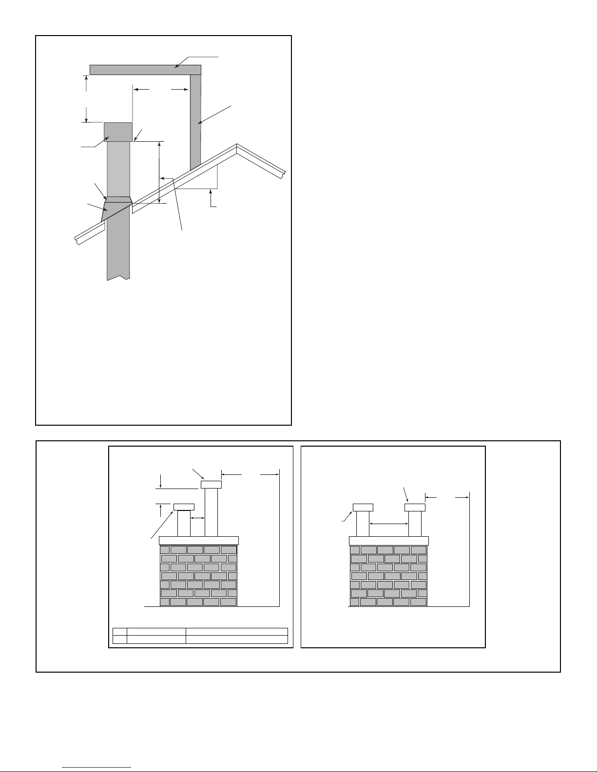
Horizontal
overhang
24 in. min.
(610 mm)
20 in.
(508 mm)
Lowest
Vertical
wall
Discharge
Termination
Opening
Cap
Storm Collar
X
12
Roof
Flashing
Roof Pitch
is X / 12
H (min.) - Minimum height
from roof to lowest
discharge opening.
Roof Pitch H (Min.) Ft. Roof Pitch H (Min.) Ft.
Flat to 6/12 1.0* Over 11/12 to 12/12 4.0
Over 6/12 to 7/12 1.25* Over 12/12 to 14/12 5.0
Over 7/12 to 8/12 1.5* Over 14/12 to 16/12 6.0
Over 8/12 to 9/12 2.0* Over 16/12 to 18/12 7.0
Over 9/12 to 10/12 2.5 Over 18/12 to 20/12 7.5
Over 10/12 to 11/12 3.25 Over 20/12 to 21/12 8.0
* 3 ft. minimum in snow regions
Figure 4.2 Minimum Height from Roof to Lowest Discharge Opening
Direct Vent Gas, Wood or Fuel
Oil Termination
20 in.
(508 mm)
(minimum) to
Perpendicular
Wall
(gas only)
(457 mm)
Gas
Termination
18 in.
A
B
Termination Caps Staggered Height
A Gas Termination Wood or Fuel Oil Termination
B 6 in.
(152 mm) min.
20 in.
(508 mm) min.
Figure 4.3 Multiple Vertical Termination
Termination Caps Same Height
Direct Vent Gas, Wood or Fuel
Oil Termination
20 in.
(508 mm)
(minimum) to
Wood or
Gas Termination
* If using decorative cap cover(s), this distance may
need to be increased. Refer to the installation instruc tions supplied with the decorative cap cover.
20 in. min. *
(508 mm)
Perpendicular
Wall
(gas only)
12 Heatilator • Caliber Multi-Sided Direct Vent • 4002-079 Rev K • 11/07
D
E
B
L
C
V
V
B
F
V
B
V
V
B
X
A
J
Fixed
Fixed
Closed
M
V
K X
RES TRI CTION ZO NE
(TE RMI NATION NOT
ALL OWE D)
AIR SU PPLY IN LET
X
GAS ME TER
V
TERMINATION CAP
H
B
Openable
Fix ed
Clo sed
V
V
O
N
A
V
V
G
Closed
TERMINATION CAP
Openable
Fixed
Closed
Measure vertical clearances
from this surface
T
Measure horizontal clearances
Alcove Clearances
from this surface.
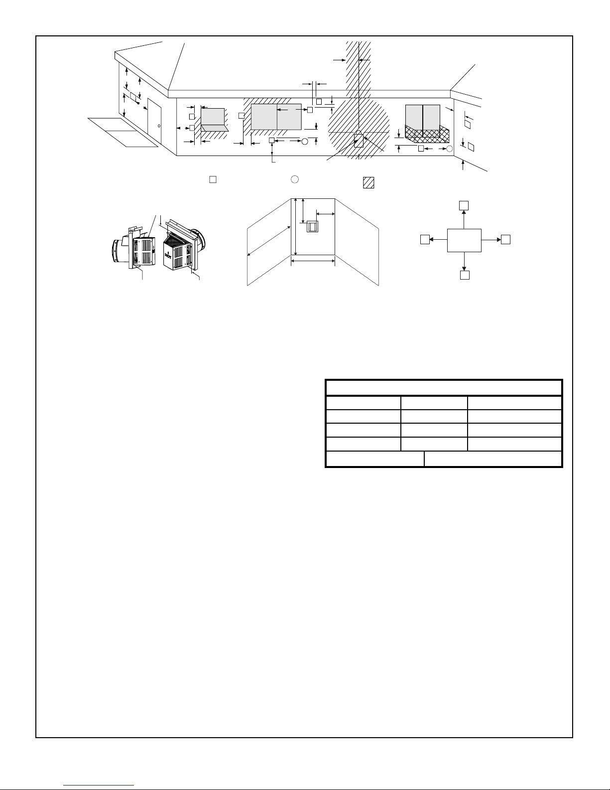
Dimension Descriptions
A Clearance above the ground, a veranda, porch, deck or balcony - 12
in. (30 cm) minimum. *
B Clearance to window or door that may be opened – 10,000 BTUs
or less, 6 in. (15 cm) minimum; 10,000-50,000 BTUs, 9 in. (23 cm)
minimum; over 50,000 BTUs, 12 in. (30 cm) minimum. *
C Clearance to permanently closed window – 12 in. (30 cm) minimum
- recommended to prevent condensation on window.
D Vertical clearance to ventilated soffi t located above the termination
within a horizontal distance of 2 ft (60 cm) from the centerline of the
termination – 18 in. (46 cm) minimum. **
E Vertical clearance to unventilated soffi t - 12 in. (30 cm) minimum. **
F Clearance to outside corner - 6 in. (15 cm) minimum.
G Clearance to inside corner - 6 in. (15 cm) minimum.
H Not to be installed above a meter/regulator assembly within 3 ft (90
cm) horizontally* from the center line of the regulator (Canada only)
I Clearance to service regulator vent outlet – 3 ft (.91 m) U.S. minimum
and 3 ft (.91 m) Canada minimum. *
J Clearance to non-mechanical air supply inlet into building or the
combustion air inlet to any other appliance – 9” (23 cm) U.S. minimum
and 12 in. (30 cm) Canada minimum. *
K Clearance to mechanical air supply inlet - 3 ft (.91 m) U.S. minimum
and 6 ft (1.8 m) Canada minimum. *
L Clearance above a paved sidewalk or paved driveway located on public
property - 7 ft (2.1 m) minimum.
A vent may not terminate directly above a sidewalk or paved driveway
which is located between two single family dwellings and serves both
dwellings.
M Clearance under veranda, porch, deck or balcony - 12 in. (30 cm)
minimum. * Recommended 30 in. (76 cm) for vinyl or plastic.
Only permitted if veranda, porch, deck or balcony is fully open on a
minimum of 2 sides beneath the fl oor. *
N Vertical clearance between two horizontal termination caps – 12 in. (30
cm) minimum.
O Horizontal clearance between two horizontal termination caps – 12 in.
(30 cm) minimum.
I
GAS METER
AIR SUPPLY INLET
Q
P
V
R
S
RESTRICTION ZONE
(TERMINATION NOT
ALLOWED)
V
V
W
U
lectrical
Service
U
V
D*
V
Clearances to Electrical Service
P 6” - Non-vinyl sidewalls
12” – Vinyl sidewalls
Q 18” – Non-vinyl soffi t and overhang
42” – Vinyl soffi t and overhang
R 8 ft.
S
min
T
max
1 cap 3 ft 2 x S actual
2 caps 6 ft 1 x S actual
3 caps 9 ft 2/3 x S actual
4 caps 12 ft 1/2 x S actual
S
= # term caps x 3 T
min
= (2/# term caps) x S (actual)
max
U 6” min. – Clearance from sides of electrical service.
W 12” min. – Clearance above electrical service.
* As specifi ed in CGA B149 Installation Codes
Note: Local codes or regulations may require different clearances.
** Clearance required to vinyl soffi t material – 30 in. (76 cm) minimum.
Note: Location of the vent termination must not interfere with access
to the electrical service.
WARNING!
In the U.S.: Vent system termination is NOT permitted in screened
porches. You must follow side wall, overhang and ground clearances
as stated in the instructions.
In Canada: Vent system termination is NOT permitted in screened
porches. Vent system termination is permitted in porch areas with two
or more sides open. You must follow all side wall, overhang and ground
clearances as stated in the instructions.
Hearth & Home Technologies assumes no responsibility for the improper
performance of the appliance when the venting system does not meet
these requirements.
Figure 4.4 Minimum Clearances for Terminations
Heatilator • Caliber Multi-Sided Direct Vent • 4002-079 Rev K • 11/07 13

5
Vent Information and Diagrams
5
A. Vent Table Key
The abbreviations listed in this vent table key are used in the
vent diagrams.
Symbol Description
V
V
H
H
First section (closest to appliance) of vertical length
1
Second section of vertical length
2
First section (closest to appliance) of horizontal length
1
Second section of horizontal length
2
Vertical
12 in.
8-1/2 in.
8-1/2 in.
WARNING
Fire Risk
Explosion Risk
Asphyxiation Risk
Do NOT connect this gas appliance to a
chimney fl ue serving a separate solid-fuel
or gas burning appliance.
• Vent this appliance directly outside.
• Use separate vent system for this
appliance.
May impair safe operation of this appliance or
other appliances connected to the fl ue.
B. Use of Elbows
CAUTION
ALL vent configuration specifications MUST be
followed.
• This product is tested and listed to these
specifi cations.
• Appliance performance will suffer if specifi cations
are not followed.
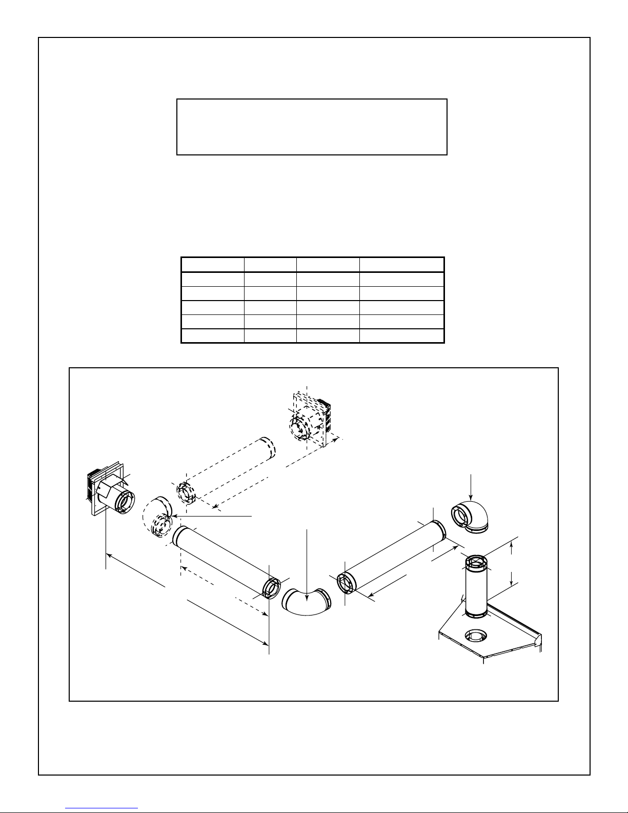
Diagonal runs have both vertical and horizontal vent aspects
when calculating the effects. Use the rise for the vertical aspect and the run for the horizontal aspect (see Figure 5.1).
Two 45° elbows may be used in place of one 90° elbow. On
45° runs, 1 ft of diagonal is equal to 8-1/2 in. horizontal run
and 8-1/2 in. vertical run. A length of straight pipe is allowed
between two 45° elbows (see Figure 5.1).
Horizontal
Figure 5.1 Using Two 45° Elbows
C. Measuring Standards
Vertical and horizontal measurements listed in the vent diagrams were made using the following standards.
• Pipe measurements are shown using the effective length
of pipe (see Figure 5.2).
• Measurements are made from the appliance outer wrap,
not from the standoffs.
• Horizontal terminations are measured to the outside
mounting surface (fl ange of exterior termination) (see
Figure 4.1).
• Vertical terminations are measured to top of last pipe
before termination cap.
• Horizontal pipe installed level with no rise
Pipe Effective Length
DVP4 4 in. (102 mm)
DVP6 6 in. (152 mm)
Effective
Length
DVP Pipe
(see chart)
DVP12 12 in. (305 mm)
DVP24 24 in. (610 mm)
DVP36 36 in. (914 mm)
DVP48 48 in. (1219 mm)
DVP6A 3to6in.(76to152mm)
DVP12A 3to12in.(76to305mm)
DVP12MI 3 to 12 in. (76 to 305 mm)
DVP24MI 3 to 24 in. (76 to 610 mm)
14 Heatilator • Caliber Multi-Sided Direct Vent • 4002-079 Rev K • 11/07
Figure 5.2 DVP Pipe Effective Length
D. Vent Diagrams
WARNING
Fire Risk
Explosion Risk
Do NOT pack insulation or other combustibles between fi restops.
• ALWAYS maintain specifi ed clearances around venting and fi restop systems.
• Install fi restops as specifi ed.
Failure to keep insulation or other material away from vent pipe may cause fi re.
The fi rst 90° elbow MUST be a starter elbow.
To replace the fi rst starter elbow with two 45° elbows, refer to Figure 5.4. All other 90° elbows can be replaced with two 45°
elbows.
General Rules:
• SUBTRACT 3 ft (914 mm) from the total H measurement for each 90° elbow installed horizontally.
SUBTRACT 1-1/2 ft (456 mm) from the total H measurement for each 45° elbow installed horizontally.
• A maximum of three 90° elbows (or six 45° elbows) may be used in any vent confi guration. Some elbows may be installed
horizontally. See Figure 5.6.
• Elbows may be placed back to back anywhere in the system as long as the fi rst 90° elbow is a starter elbow except as
shown in Figure 5.4.
• When penetrating a combustible wall, a wall shield fi restop must be installed.
• When penetrating a combustible ceiling, a ceiling fi restop must be installed.
• Horizontal runs of vent do not require vertical rise; horizontal runs may be level.
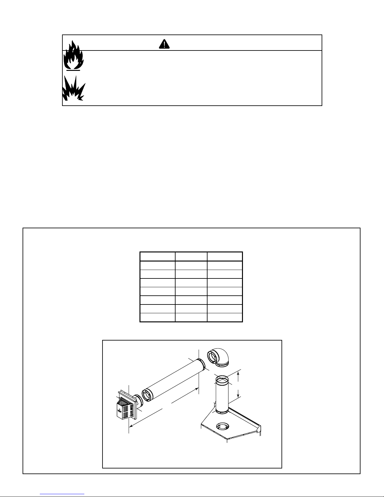
Top Vent—Horizontal Termination—One Elbow
V1 min. V1 max. H1 max.
0* - 24 in./635 mm
4 in./102 mm - 4 ft/1.22 m
6 in./152 mm - 6 ft/1.83 m
12 in./305 mm - 11 ft/3.35 m
18 in./457 mm - 18 ft/5.49 m
24 in./610 mm - 25 ft/7.62 m
- 25 ft/7.62 m 25 ft/7.62 m
You may install the elbow directly on top of
H
1
Table 5.1
the appliance.
V
1
Figure 5.3 Top Vent-Horiztonal Termination-One Elbow
Heatilator • Caliber Multi-Sided Direct Vent • 4002-079 Rev K • 11/07 15
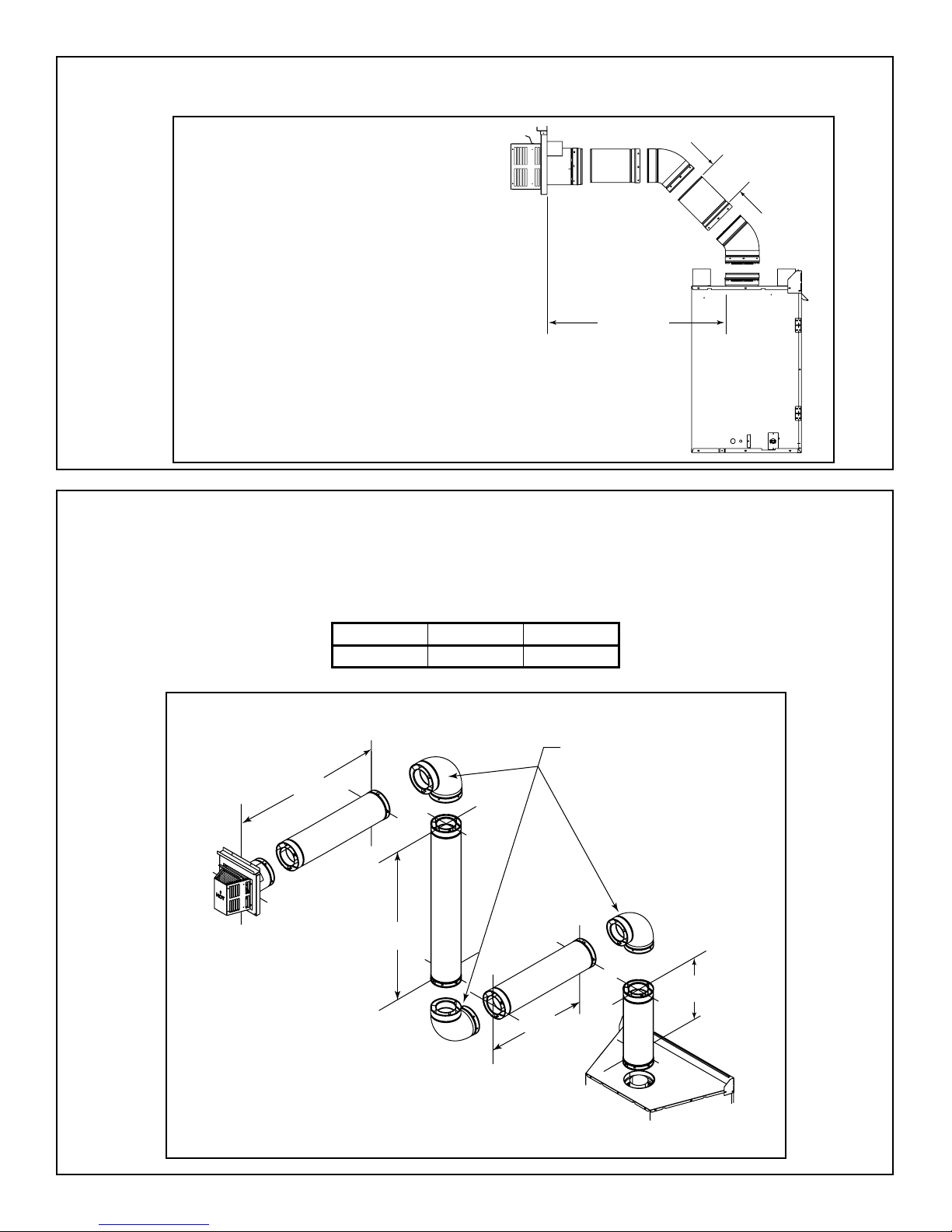
Top Vent—Horizontal Termination—Two 45° Elbows
Installation requirements to replace the fi rst 90° elbow with two 45° elbows:
Figure 5.4 Minimum Installation Requirements for
Two 45° Elbows-Top Vent-Horizontal Termination
Top Vent—Horizontal Termination—Three Vertical Elbows
See Figure 5.6 for information about installing elbows horizontally.
4 ft min.
(1.22 m)
25 ft max.
(7.62 m)
Table 5.2
V1 min. V1 + V2 max. H1 + H2 max.
12 in./305 mm 24 ft/7.32 m 19 ft/5.79 m
H
2
V
2
Installed
Vertically
H
1
V
1
Figure 5.5 Three Vertically Installed 90° Elbows
16 Heatilator • Caliber Multi-Sided Direct Vent • 4002-079 Rev K • 11/07
Top Vent—Horizontal Termination—Two or Three Elbows
You may use a maximum of three 90° elbows (or six 45° elbows) in any vent confi guration, Some may be installed hori-
zontally.
Note: Subtract 3 ft (914 mm) from the total horizontal
measurement for each 90° elbow installed horizontally.
Subtract 1-1/2 ft (456 mm) from the total horizontal
measurement for each 45° elbow installed horizontally.
Table 5.3
V1 min. V1 max. H1 + H2 max. H1 + H2 + H3 max.
6 in./152 mm - 6 ft/1.83 m -
12 in./305 mm - 11 ft/3.35 m 11 ft/3.35 m
18 in./457 mm - 18 ft/5.49 m 18 ft/5.49 m
24 in./810 mm - 25 ft/7.62 m 25 ft/7.62 m
- 25 ft/7.62 m 25 ft/7.62 m 25 ft/7.62 m
Horizontally
H
2
Figure 5.6 Two or Three Elbows, some Horizontal
H
2
H
3
Installed
H
1
Installed
Vertically
V
1
Heatilator • Caliber Multi-Sided Direct Vent • 4002-079 Rev K • 11/07 17
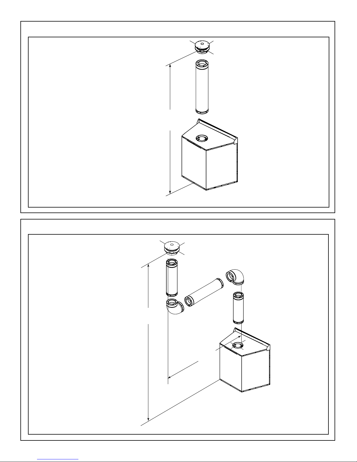
Top Vent—Vertical Termination—No Elbows
12 ft (3.66 m) min.
60 ft (18.29 m) max.
Figure 5.7 Vertical Termination - No Elbows
Top Vent—Vertical Termination—Two Elbows
12 ft (3.66 m) min.
60 ft (18.29 m) max.
Maximum horizontal
run is 100% of
vertical, but cannot
exceed 26 ft (7.92 m)
Figure 5.8 Vertical Termination - Two Elbows
18 Heatilator • Caliber Multi-Sided Direct Vent • 4002-079 Rev K • 11/07
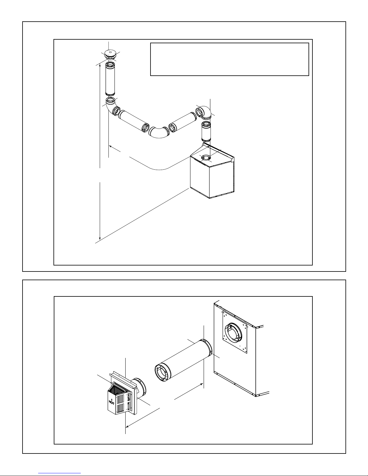
Top Vent—Vertical Termination—Three Elbows
Note: Subtract 3 ft (914 mm) from the total horizontal
measurement for each 90° elbow installed horizontally.
Subtract 1-1/2 ft (456 mm) from the total horizontal
measurement for each 45° elbow installed horizontally.
Maximum horizontal run is
100% of vertical, but cannot
exceed 26 ft (7.92 m)
12 ft (3.66 m) min.
60 ft (18.29 m) max.
Figure 5.9 Vertical Termination - Three Elbows (some horizontal)
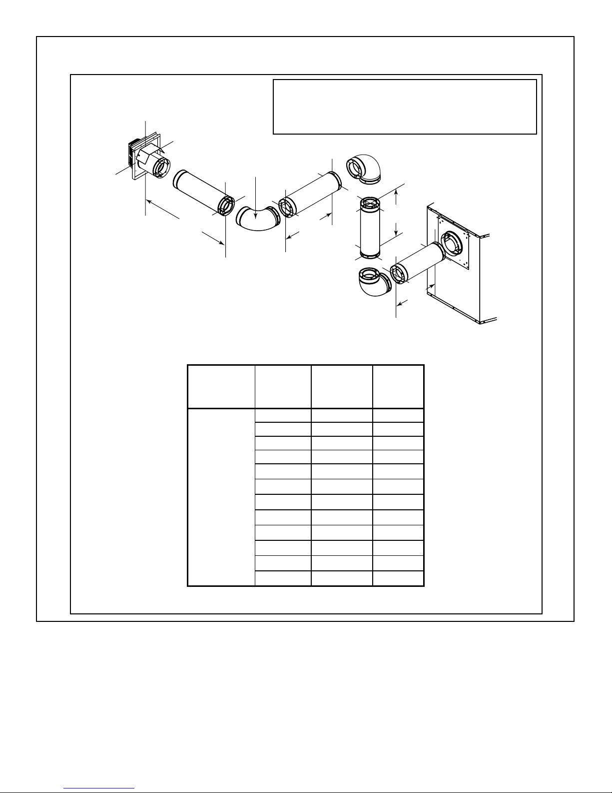
Rear Vent—Horizontal Termination—No Elbows
18 in. (457 mm) max.
Figure 5.10 Horizontal Termination - No Elbows
Heatilator • Caliber Multi-Sided Direct Vent • 4002-079 Rev K • 11/07 19
Rear Vent—Horizontal Termination—One 45° Elbow
18 in. (457 mm) max.
Figure 5.11 Horizontal Termination - One 45° Elbow
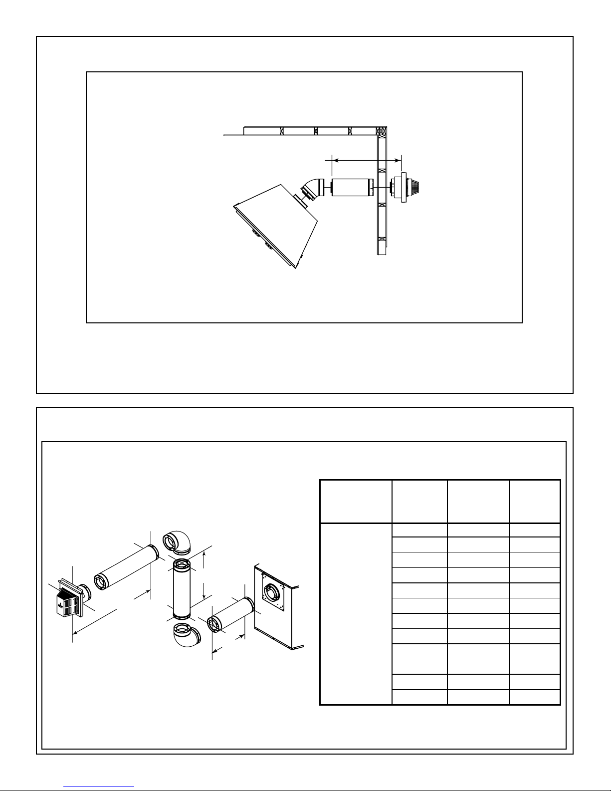
Rear Vent—Horizontal Termination—Two Elbows
V
1
H
2
H
1
Table 5.4
Gas Appliance
2-Elbow
Parameters H1 Max
Multi-Sided 0 12 in./305 mm 3 ft/.91 m
12 in./305 mm 12 in./305 mm 4 ft/1.22 m
24 in./610 mm 12 in./305 mm 5 ft/1.52 m
0 24 in./610 mm 5 ft/1.52 m
12 in./305 mm 24 in./610 mm 5 ft/1.52 m
24 in./610 mm 24 in./610 mm 6 ft/1.83 m
0 36 in./914 mm 6 ft/1.83 m
12 in./305 mm 36 in./914 mm 6 ft/1.83 m
24 in./610 mm 36 in./914 mm 7 ft/2.13 m
0 48 in./1219 mm 8 ft/2.44 m
12 in./305 mm 48 in./1219 mm 8 ft/2.44 m
24 in./610 mm 48 in./1219 mm 8 ft/2.44 m
Total Vert
V Min.
Total Horiz
H1+H2
Figure 5.12 Horizontal Termination - Two Elbows
20 Heatilator • Caliber Multi-Sided Direct Vent • 4002-079 Rev K • 11/07
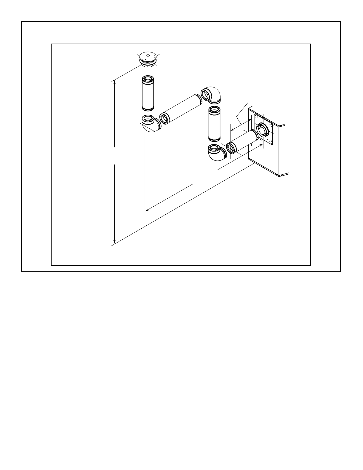
Rear Vent—Horizontal Termination—Three Elbows
Note: Subtract 3 ft (914 mm) from the total horizontal
measurement for each 90° elbow installed horizontally.
Subtract 1-1/2 ft (456 mm) from the total horizontal
measurement for each 45° elbow installed horizontally.
Installed
Horizontally
H
3
H
V
2
1
H
1
Gas Appliance
3-Elbow
Parameters H1 Max
Multi-Sided 0 12 in./305 mm 4 ft/1.22 m
Caliber 12 in./305 mm 12 in./305 mm 4 ft/1.22 m
Maxus 24 in./610 mm 12 in./305 mm 4 ft/1.22 m
Caliber NXT 0 24 in./610 mm 5 ft/1.52 m
12 in./305 mm 24 in./610 mm 5 ft/1.52 m
24 in./610 mm 24 in./610 mm 5 ft/1.52 m
12 in./305 mm 36 in./914 mm 5 ft/1.52 m
24 in./610 mm 36 in./914 mm 5 ft/1.52 m
12 in./305 mm 48 in./1219 mm 6 ft/1.83 m
24 in./610 mm 48 in./1219 mm 6 ft/1.83 m
Figure 5.13 Horizontal Termination - Three Elbows
Table 5.5
Total Vert
V Min.
0 36 in./914 mm 5 ft/1.52 m
0 48 in./1219 mm 6 ft/1.83 m
Total Horiz
H1+H2+H3
Heatilator • Caliber Multi-Sided Direct Vent • 4002-079 Rev K • 11/07 21
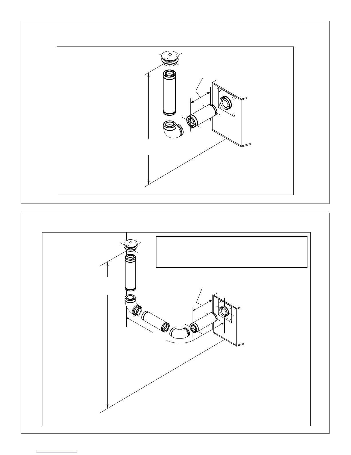
Rear Vent—Vertical Termination—One Elbow
12 ft (3.66 m) min.
60 ft (18.29 m) max.
Figure 5.14 Vertical Termination - One Elbow
0 min.
6 ft (1.83 m) max.
Rear Vent—Vertical Termination—Two Elbows
Note: Subtract 3 ft (914 mm) from the total horizontal
measurement for each 90° elbow installed horizontally.
Subtract 1-1/2 ft (456 mm) from the total horizontal
measurement for each 45° elbow installed horizontally.
12 ft (3.66 m) min.
60 ft (18.29 m) max.
Maximum horizontal
run is 100% of
vertical, but cannot
exceed 26 ft (7.92 m)
0 min.
6 ft (1.83 m) max.
Figure 5.15 Vertical Termination - Two Elbows
22 Heatilator • Caliber Multi-Sided Direct Vent • 4002-079 Rev K • 11/07
Rear Vent—Vertical Termination—Three Vertical Elbows
12 ft (3.66 m) min.
60 ft (18.29 m) max.
Maximum horizontal run is
100% of vertical, but cannot exceed 26 ft (7.92 m).
0 min.
6 ft (1.83 m) max.
Figure 5.16 Vertical Termination - Three Vertical Elbows
Heatilator • Caliber Multi-Sided Direct Vent • 4002-079 Rev K • 11/07 23
G
6
Vent Clearances and Framing
6
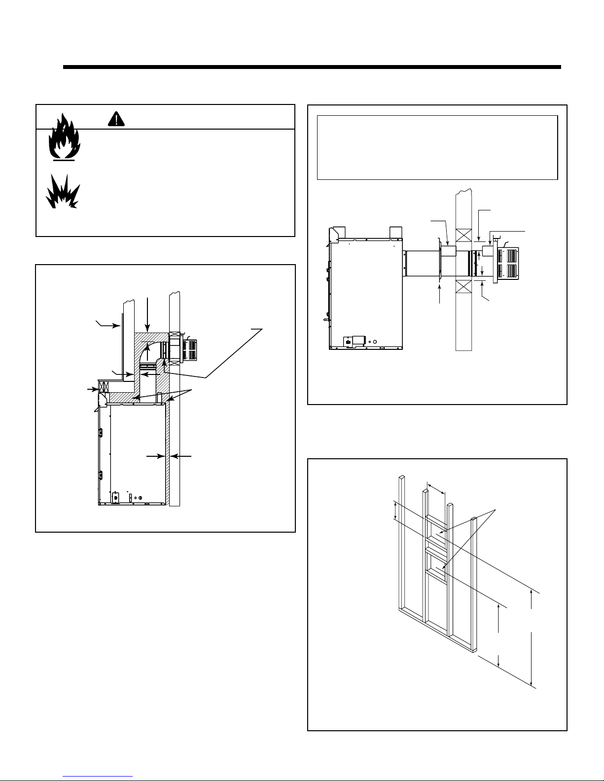
A. Pipe Clearances to Combustibles
Fire Risk
Explosion Risk
Maintain vent clearance to combustibles as
specifi ed.
• Do not pack air space with insulation or
Failure to keep insulation or other materials
away from vent pipe may cause fi re.
Drywall
1 in. (25 mm)
2 x 4 or
2 x 6
header
WARNING
other materials.
3 in.
(76 mm)
Air space clearances
to bottom and sides
of horizontal pipe
must be at least
1 in. (25 mm)
No combustible
framing to be
located within
shaded area.
Note: Heat shields MUST overlap by a minimum of 1-1/2 in.
(38 mm). The heat shield is designed to be used on a wall
4 in. to 7-1/4 in. (102 mm to 184 mm) thick. If wall thickness
is less than 4 in. (102 mm) the existing heat shields must be
field trimmed. If wall thickness is greater than 7-1/4 in. (184
mm) a DVP-HSM-B will be required.
Heat
Shield
Wall
Shield
Firestop
WALL
Figure 6.2 Minimum Horizontal Venting Clearances to Combustible Materials
3 in. (76 mm)
top clearance
Heat
Shield
1 in. (25 mm)
clearance
bottom & sides
1/2 in. (13 mm)
minimum to
WALL
perpendicular
wall.
Figure 6.1 Minimum Top Vented DV Pipe Clearances
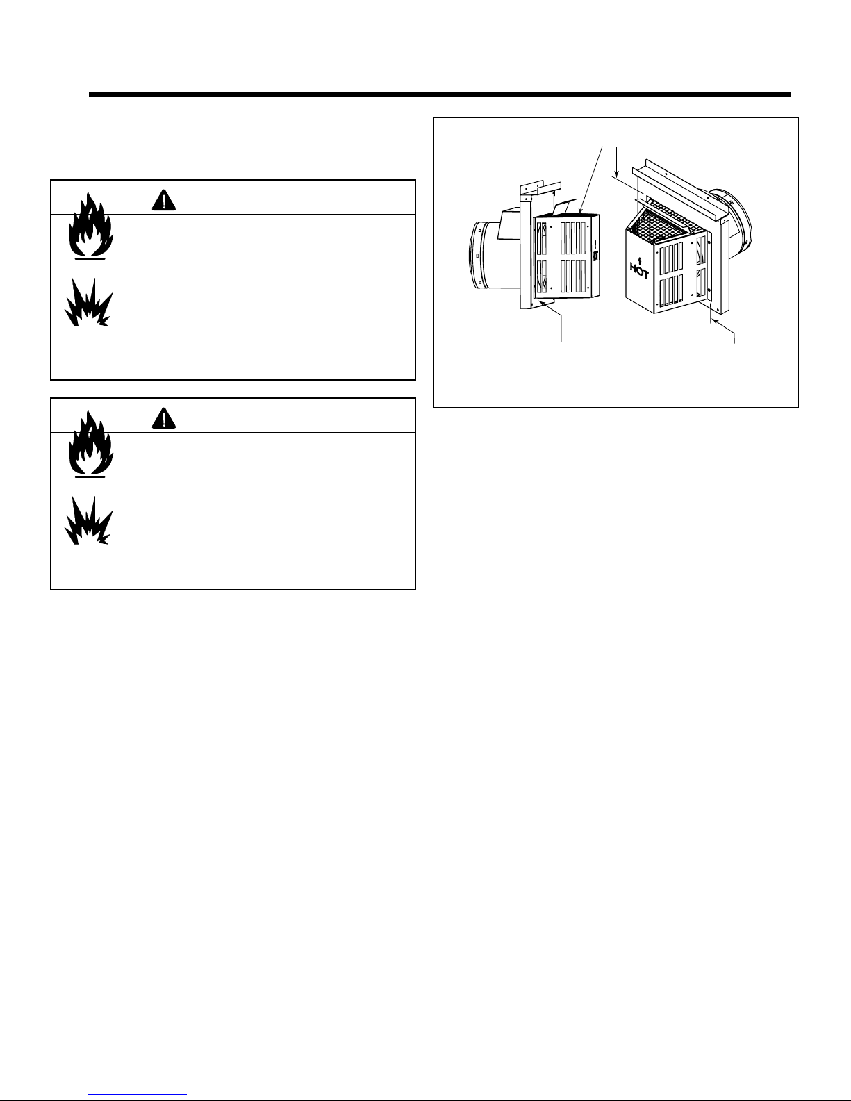
B. Wall Penetration Framing
• Wherever a combustible wall is penetrated, the hole must
be framed with a wall shield fi restop. This shield maintains
minimum clearances and restricts cold air infi ltration.
• If the wall being penetrated is of noncombustible materials
(material which will not ignite or burn, or has a UL fi re rating
of zero), a 9 in. (229 mm) diameter hole is acceptable.
• Whenever a wall is penetrated the wall shield fi restop
is only required on one side and no heat shield is
necessary.
• If your local inspector requires the wall shield fi restop on
both sides of the wall, then both wall shield fi restops must
have a heat shield attached to them.
12 in.
The center of the
framing hole is
1 in. [25mm] above
the center of the
horizontal vent pipe.
Framing should be
constructed of 2 X 4
lumber or heavier.
#ENTEROFPIPE
Figure 6.3 Exterior Wall Hole
10 in.
Vent framing hole.
DO NOT PACK
WITH INSULATIN
MATERIAL.
45-3/4 in.*
(1162 mm)
29 in.*
(737 mm)
24 Heatilator • Caliber Multi-Sided Direct Vent • 4002-079 Rev K • 11/07
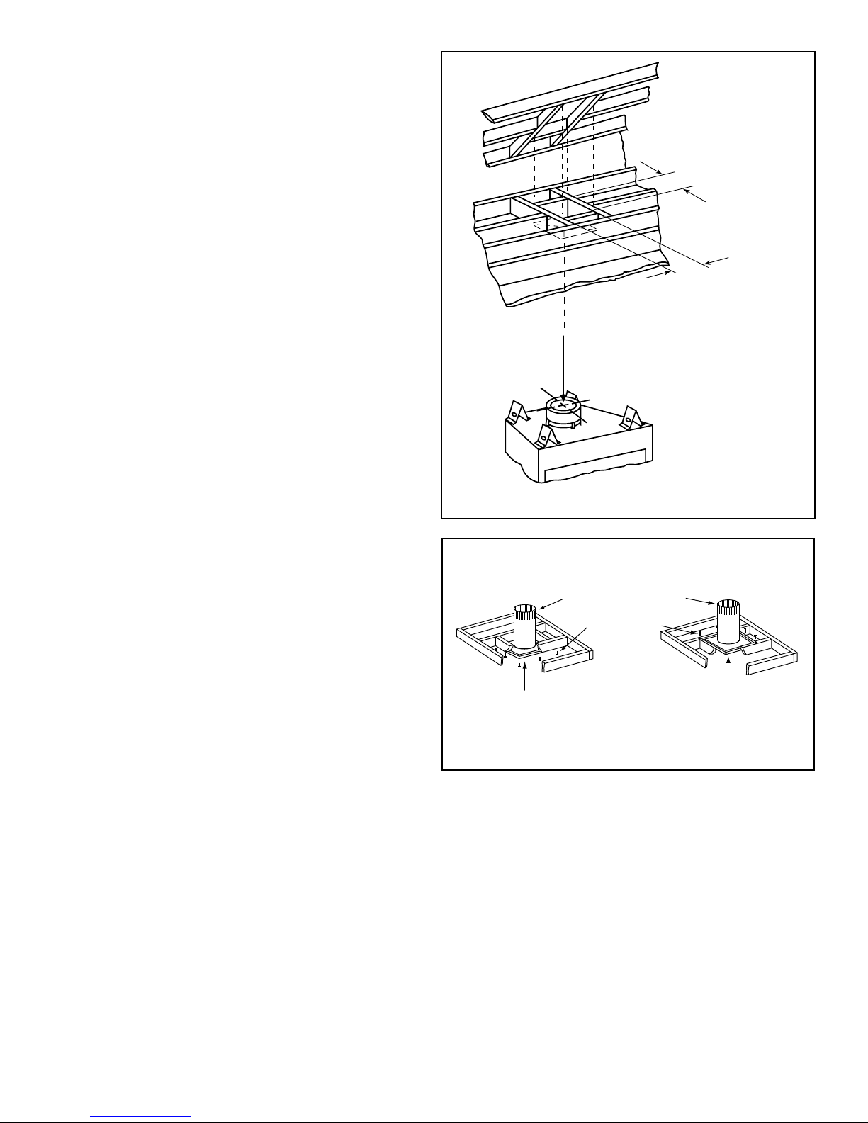
C. Install the Ceiling Firestop
• Frame an opening 10 in. by 10 in. whenever the vent
system penetrates a ceiling/fl oor (see Figure 6.4).
• Frame the area with the same sized lumber as used in
ceiling/fl oor joist.
• When installing a top vent vertical termination appliance
the hole should be directly above the appliance, unless
the fl ue is offset.
• The ceiling fi restop may be installed above or below the
ceiling. Refer to Figure 6.5.
• Secure with three fasteners on each side.
• Do not pack insulation around the vent. Insulation must
be kept away from the pipe.
Attic Above
10 in. (254 mm)
10 in.
(254 mm)
Hole should measure
10 in. x 10 in.
(254 mm x 254 mm)
inside to inside
Figure 6.4 Installing Ceiling Firestop
Install attic insulation shields before
or after installation
of vent system.
3 fasteners
per side
Ceiling firestop
installed below ceiling.
Figure 6.5 Installing Ceiling Firestop & Attic Insulation Shield
Ceiling firestop
installed above ceiling.
Heatilator • Caliber Multi-Sided Direct Vent • 4002-079 Rev K • 11/07 25
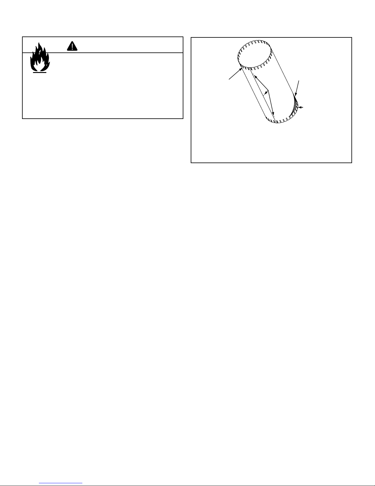
D. Install Attic Insulation Shield
WARNING
Fire Risk
Keep loose materials or blown insulation
from touching the vent pipe.
• National building codes recommend using
attic shield to keep loose materials/blown
insulation from contacting vent.
• Hearth & Home Technologies requires
the use of an attic shield.
Flat Ceiling Installation
• Remove one shield from box.
Note: Cut p r eviously inst alled bat t insulat ion to ma ke r o o m
for the attic insulation shield.
• Wrap shield around pipe if pipe is already installed in area
to be insulated.
• Match the three holes in each side and fasten with three
screws to form a tube.
• Bend four tabs inward on bottom of shield where it rests on
¨
the ceiling fi restop to maintain the air space between the
pipe and shield. Set the shield on the ceiling fi restop.
• Bend all tabs inward 90° around the top of the shield.
These tabs must be used to prevent blow-in insulation from
getting between the shield and vent pipe, and to maintain
clearance.
Bend all tabs inward
90° to maintain
clearance and
prevent insulation
from falling inside
Figure 6.6 Attic Insulation Shield
Insert 3
screws
Laser-etched
cut lines
Bend 4 tabs
inward 90°
to maintain
clearance
Vaulted Ceiling Installation
• The attic insulation shield has been laser-etched with cut
lines and ceiling pitches to make fi eld trimming easier.
• Remove one shield from box.
Note: Cut p r eviously inst alled bat t insulat ion to ma ke r o o m
for the attic insulation shield.
• Cut the attic insulation shield (if application is for vaulted
ceiling) using a laser-etched cut line, to fi t your ceiling
pitch. Snip cut edge to create three bend tabs.
• Wrap shield around pipe if pipe is already installed in area
to be insulated.
• Match the three holes in each side and fasten with three
screws to form a tube.
• Bend four of the remaining tabs inward 90° on bottom
of shield to maintain the air space between the pipe and
shield. Cover the resulting holes with aluminum tape. Set
the shield on the ceiling fi restop.
• Bend all tabs inward 90° around the top of the shield.
These tabs must be used to prevent blow-in insulation from
getting between the shield and vent pipe, and to maintain
clearance.
26 Heatilator • Caliber Multi-Sided Direct Vent • 4002-079 Rev K • 11/07
7
Appliance Preparation
7
CAUTION
Sharp Edges
• Wear protective gloves
and safety glasses during
installation.
A. Appliance Placement
This appliance may be placed on a smooth combustible or
noncombustible, continuous, fl at surface. When the appli-
ance is installed directly on carpeting, tile or other combustible material other than wood fl ooring, the appliance shall be
installed on a metal or wood panel ( hearth sheet) extending
the full width and depth of the appliance. Slide the assembly
into position and level from side-to-side and front-to-back.
Shim the appliance as necessary. It is acceptable to use
wood shims.
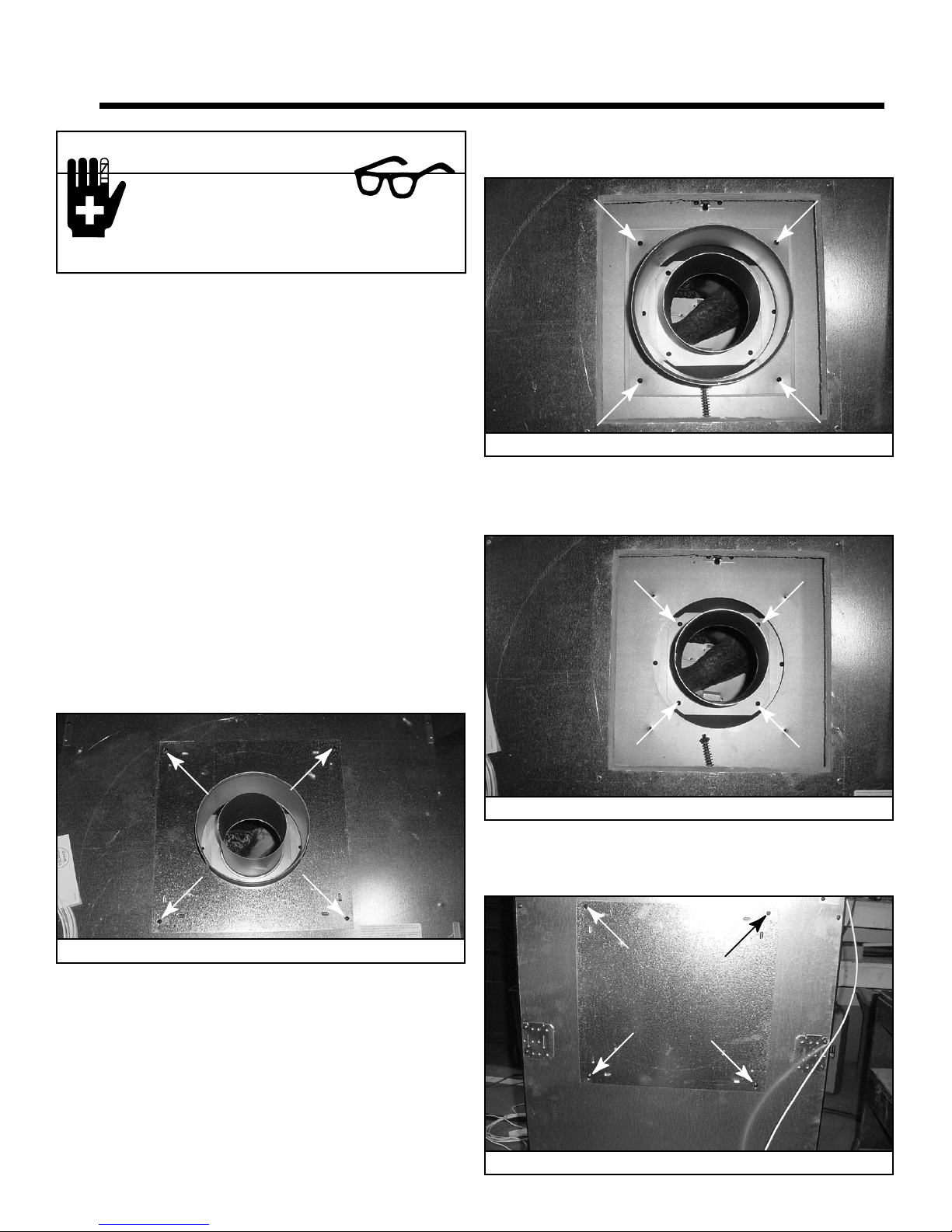
B. Secure the Appliance
Secure the appliance by bending out the nailing fl anges on
each side of the appliance and nail to the framing. The nailing fl anges have been positioned 5/8 in. back from the front
of the appliance to allow for the addition of drywall.
• Remove four screws holding outer collar to appliance top.
See Figure 7.2. Remove outer collar.
Figure 7.2 Outer Collar - Remove Four Screws
• Remove four screws holding inner collar to appliance top.
See Figure 7.3. Remove inner collar.
C. Convert from Top Vent to Rear Vent
• Remove four screws holding the plate surrounding the
fl ue. See Figure 7.1 Remove plate and set aside.
Figure 7.1 Cover Plate - Remove Four Screws
Figure 7.3 Inner Collar - Remove Four Screws
• Remove four screws holding outer shell cover. See Figure
7.4. Remove outer shell cover and set aside. (Cover has
insulation attached.)
Heatilator • Caliber Multi-Sided Direct Vent • 4002-079 Rev K • 11/07 27
Figure 7.4 Outer Shell Cover - Remove Four Screws
 Loading...