

Heatilator GCBC36LE Installation Instructions Manual
INSTALLATION INSTRUCTIONS
Flip manual over for “Operating and Maintenance Instructions.”
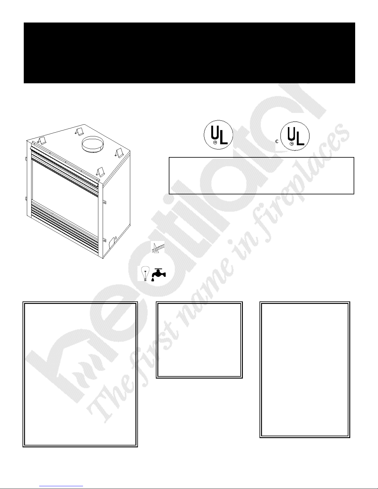
CALIBER SERIES B-VENT SERIES
DECORATIVE GAS APPLIANCE
Read these installation instructions completely
before beginning installation. Failure to follow
them could cause an appliance malfunction resulting in serious injury and/or property damage.
TABLE OF CONTENTS
I. INSTALLATION
Preparation..............................................................
A.
Location and Clearances.........................................
B.
Framing....................................................................
C.
Set The Unit.............................................................
D.
Venting.....................................................................
E.
Utilities.....................................................................
36” and 42” Series
U.S. Patent 5,613,487
F.
Finishing...................................................................
G.
Firebox Preparation.................................................
H.
3
4
5
5
6
12
14
14
FOR YOUR SAFETY
What to do if you smell gas:
• Do not try to light any
appliance.
• Do not touch any electrical
switch.
• Do not use any phone in
your building.
• I m m e d i a t e ly call your gas
supplier from a neighbor’s
p h o n e. Follow the gas
supplier’s instructions.
• If you cannot reach yo u r
gas supplier, call the fire
department.
Heatilator 1915 W. Saunders Street Mt. Pleasant, IA 52641 a HON INDUSTRIES company
FOR YOUR SAFETY
Do not store or use
gasoline or other
f l a m m a ble va p o rs
and liquids in the
vicinity of this or any
other appliance.
WARNING
I m p roper installation,
adjustment, alteration,
s e rvice or maintenance can cause
i n j u ry or pro p e rt y
damage. Refer to this
m a nual. For assistance or add i t i o n a l
i n formation, consult a
qualified installer, service agency or the gas
supplier.
A. PREPARATION
12-97 2i 28887A
U.S. and Canada Certification
The CALIBER Series Gas Appliance has been tested
in accordance with the ANSI standard Z21.50-1996
(Decorative). In Canada, the current CAN/CGA 2.22M96, IR41, P4, and IR55 and have been LISTED by
Underwriters Laboratories Inc. for installation as
described in this manual. All components are UL,
AGA, CGA or CSA safety certified.
Local Codes
This installation must conform with local codes. In the
absence of local codes comply with the National Fuel
Gas Code, ANSI Z223.1-latest edition, in the U.S.A.
and the CAN/CGA B149, Installation Codes, in
Canada.
For assistance during installation contact your local
dealer or contact Heatilator Customer Relations
Department, 1915 W. Saunders Street, Mt. Pleasant,
Iowa 52641.
HEATILATOR®is a registered trademark of Hearth
Technologies, Inc., a HON INDUSTRIES company.

Note: Minimum and maximum clearances must
be maintained at all times. Illustrations
throughout these instructions reflect typical
installations and are for design purposes only.
Actual installation may vary slightly due to individual design preferences.
The illustrations and diagrams used throughout
these installation instructions are not drawn to
scale.
Tools and building supplies normally
required for installation:
Saw Wall-finishing materials
Pliers Framing material
Hammer Fireplace surround
Phillips screwdriver Caulking material
Tape measure Gloves
Plumb line Square
Level Electrical drills/bits
CALIBER Nomenclature
Catalog Number Description
GCBC36LE Appliance Order Code Number
GC Gas Caliber
B B-Vent
C Circulating
36 36 - 36” Unit
42 - 42” Unit
LE No suffix - Standing Pilot, Natural Gas
L - Standing Pilot, Propane Gas
E - Electronic Ignition, Natural Gas
LE - Electronic Ignition, Propane Gas
GCBC36LERF Appliance Order Code Number with Upgrade Code Number
R Refractory Upgrade
F Fan Kit Upgrade
EXAMPLE
GCBC36LERF Gas CALIBER, B-Vent, Heat Circulating, 36”, Propane Gas, Electronic Ignition
unit with Refractory and Fan Kit Upgrades.
12-97 3i 28887A
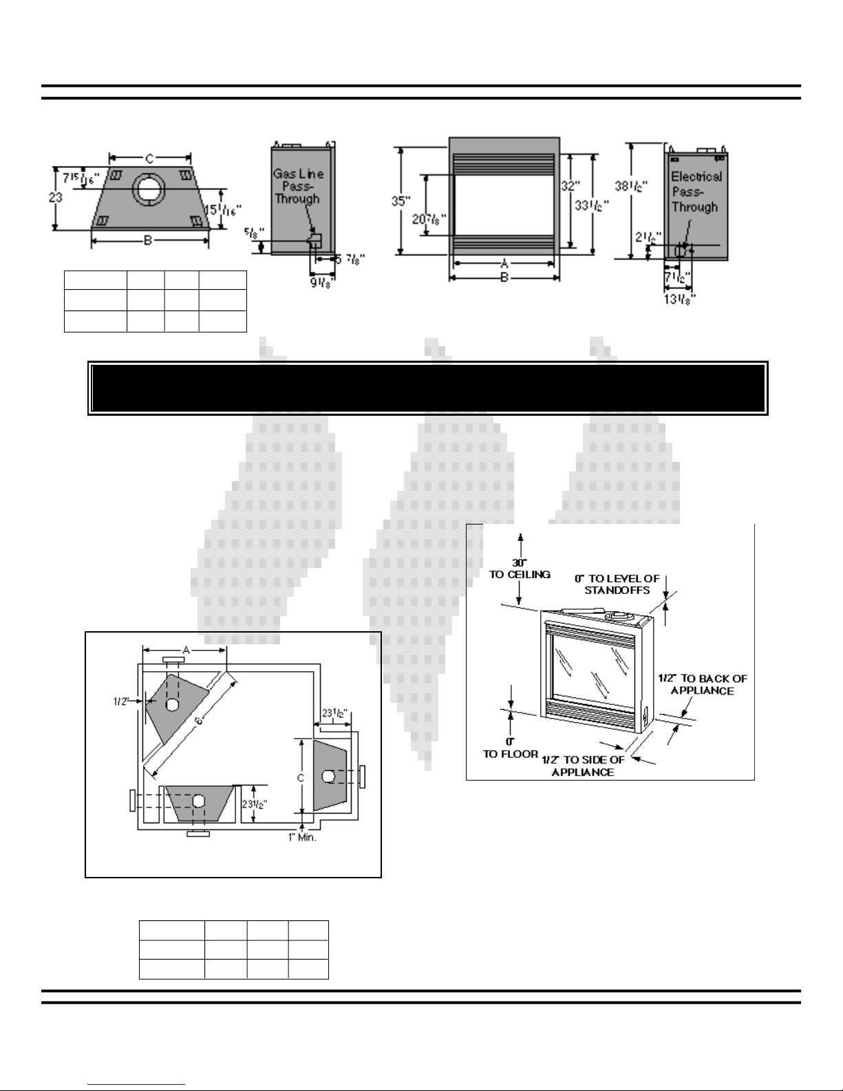
B. LOCATION AND CLEARANCES
Model A B C
36" Series 36" 41" 241/2"
42" Series 42" 47" 301/2"
DUE TO HIGH TEMPERATURES, THE APPLIANCE SHOULD BE LOCATED OUT OF TRAFFIC AND
AWAY FROM FURNITURE AND DRAPERIES.
Left Hand
Side
Unit Dimensions
Right Hand
Side
1. APPLIANCE LOCATIONS AND SPACE
REQUIREMENTS
Figure 1 illustrates a variety of ways the appliance
may be located in a room. The CALIBER Series may
be installed directly on the floor or raised on a hearth.
These appliances are certified for installation in a bedroom or a bed/sitting room in the U.S. and Canada
provided that the bedroom or bathroom have a volume
of at least 1500 cubic feet.
Common venting of this gas appliance with other gas
appliances is NOT allowed in multi-family dwellings.
2. CLEARANCES
Figure 2 shows all clearances that must be maintained around the appliance. See page 9 for termination cap clearances. See Figures 4 and 15
for vent clearances.
Figure 2
Appliance Clearances to Combustible Materials
A hearth extension is not required for this appliance.
Figure 1
Appliance Locations
Model A B C
36" Series 505/8" 715/8" 42"
42" Series 551/4" 775/8" 48"
12-97 4i 28887A

C. FRAMING
Figure 3
Framing
Figure 3 shows a typical framing of this appliance
using combustible materials. All required clearances
to combustibles must be adhered to.
*** from base of appliance
CAUTION
WEAR GLOVES AND SAFETY GLASSES
FOR PROTECTION.
CAUTION
PROVIDE ADEQUATE CLEARANCES
AROUND THE AIR OPENINGS INTO THE
COMBUSTION CHAMBER AND ADEQUATE
ACCESSIBILITY CLEARANCES FOR SERVICING AND PROPER OPERATION.
Model 36" Series 42" Series
A 421/4" 481/4"
D. SETTING THE UNIT
1. Positioning the firebox
This appliance may be placed on a smooth
combustible or noncombustible continuous, flat
surface. When the appliance is installed direct-
ly on carpeting, tile or other combustible material
other than wood flooring, the appliance shall be
installed on a metal or wood panel extending the
full width and depth of the appliance.
unit into position and level the appliance from
Slide the
side-to-side and front-to-back. Shim with noncombustible material as necessary.
Secure the appliance by bending out the nailing
flanges on each side of the appliance and nail to
framing. The nailing flanges have been positioned
5/8" back from the front of the unit to allow the addition of drywall.
12-97 5i 28887A
12-97 6i 28887A
E. VENTING
NOTE: THIS APPLIANCE REQUIRES A 5 INCH B-VENT FOR OPERATION. NEVER DOWNSIZE PIPE.
a. Clearances. See Figure 4 for clearance information.
b. Vent Lengths. Various venting configurations are
shown in Figures 5 and 6 from which maximum vent
runs can be determined.
WARNING - RISK OF FIRE
ALWAYS MAINTAIN MINIMUM CLEARANCES OR GREATER AROUND THE
VENT SYSTEM. DO NOT PACK AIR
SPACES WITH INSULATION OR OTHER
MATERIAL.
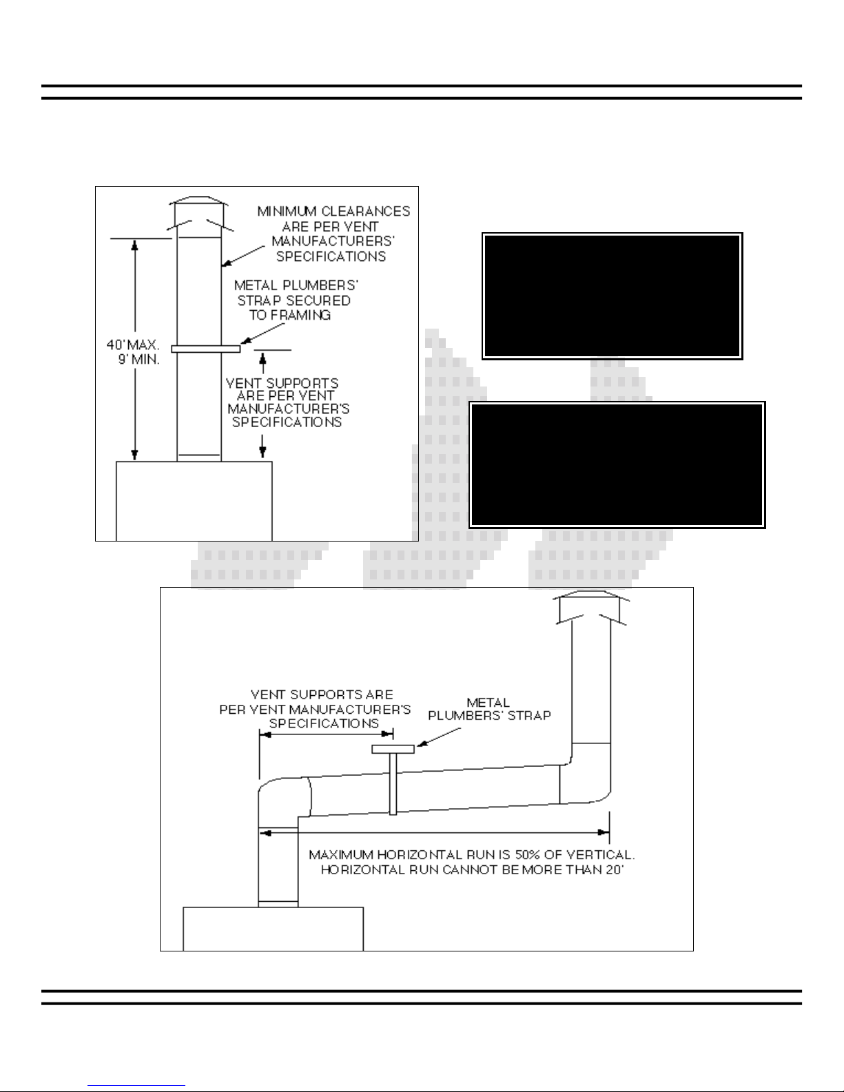
WARNING
THE HORIZONTAL RUN OF VENT MUST HAVE
A 1/4" RISE FOR EVERY 1 FT. OF RUN
TOWARDS THE TERMINATION. NEVER
ALLOW THE VENT TO RUN DOWNWARD.
THIS COULD CAUSE HIGH TEMPERATURES
AND MAY CREATE A FIRE HAZARD.
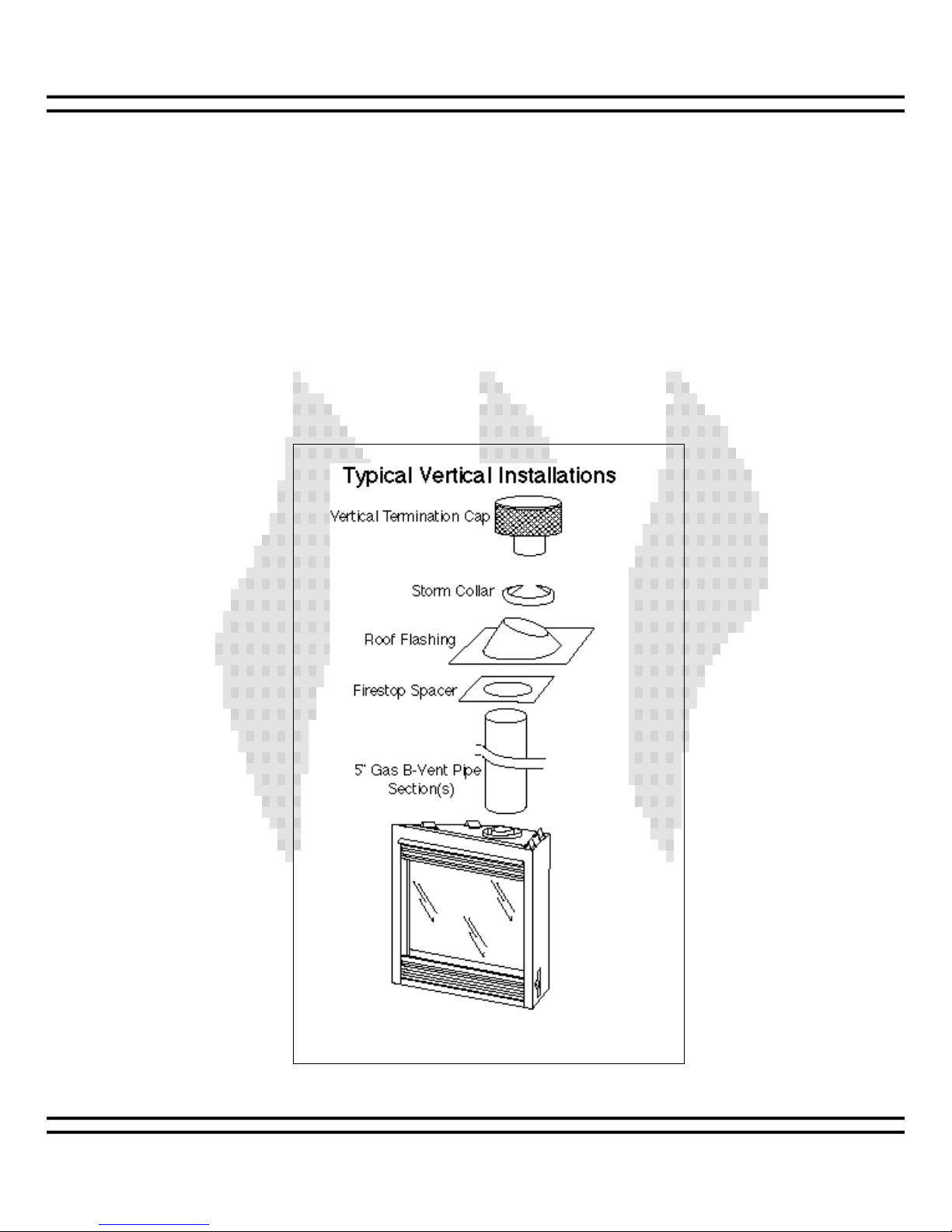
Figure 4
Vertical Termination Clearances
Figure 5
Vertical Termination Vent Lengths
12-97 7i 28887A
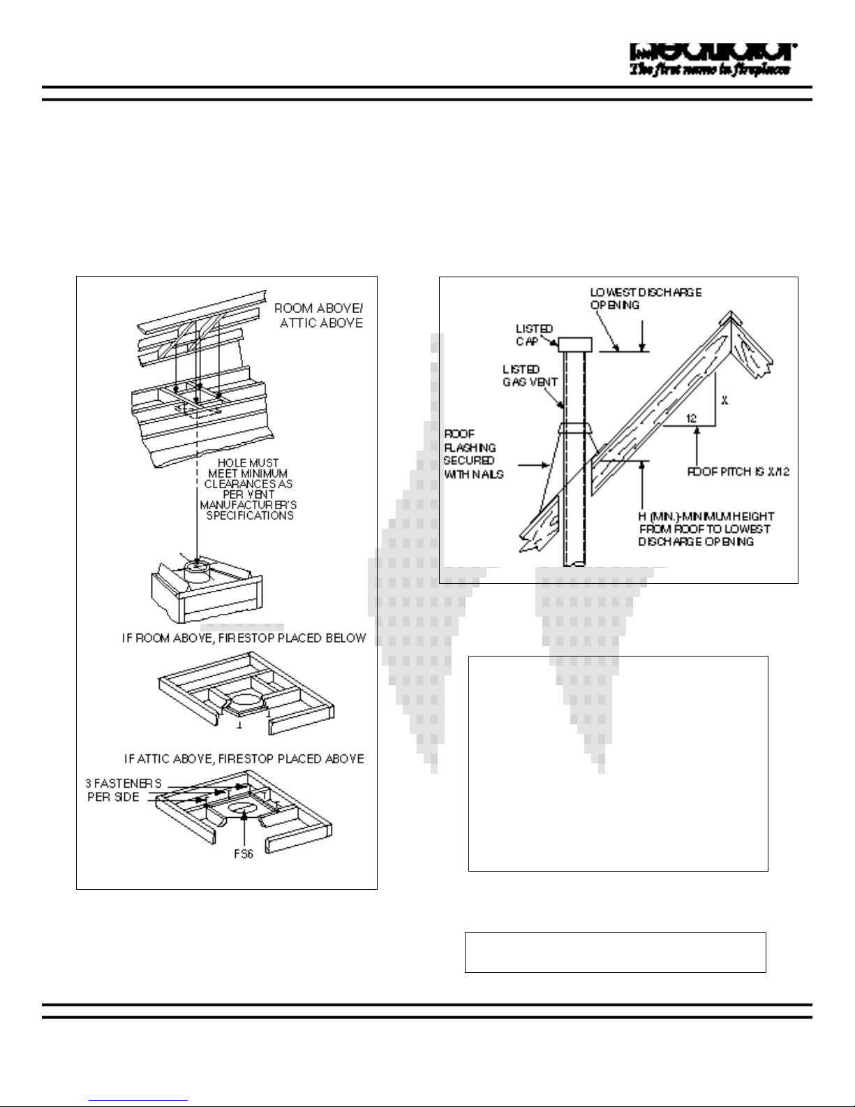
Figure 7
Vent Height for Vertical Termination
Table 1
Vent Height
c. Firestop Spacer/Vent Installation.
Frame an opening and install a firestop spacer whenever the vent penetrates a ceiling/floor area, as
shown in Figure 6. Frame the opening with the same
sized lumber as used in the ceiling/floor joists. Unless
the flue is offset, the hole should be directly above the
appliance. DO NOT pack insulation around the vent.
Assemble vent sections with three screws per joint.
d. Chase/Termination Installation. Figure 7 a n d
Table 1 specify minimum vent heights for various
pitched roofs. Vent sections may have to be cut to a
certain length.
These vent heights are necessary for safety and do
not ensure draft-free operation. Trees, buildings,
adjoining roof lines, adverse conditions, etc., may
create a need for a taller vent should down drafting
occur.
Figure 6
Installing the firestop spacer
Roof Pitch H (Min.) Ft.
Flat to 6/12 ...........................................1.0
6/12 to 7/12 ..........................................1.25
Over 7/12 to 8/12..................................1.5
Over 8/12 to 9/12..................................2.0
Over 9/12 to 10/12................................2.5
Over 10/12 to 11/12..............................3.25
Over 11/12 to 12/12..............................4.0
Over 12/12 to 14/12..............................5.0
Over 14/12 to 16/12..............................6.0
Over 16/12 to 18/12..............................7.0
Over 18/12 to 20/12..............................7.5
Over 20/12 to 21/12..............................8.0
Note: To ensure proper operation, verify all
venting and the termination is unobstructed.
 Loading...