

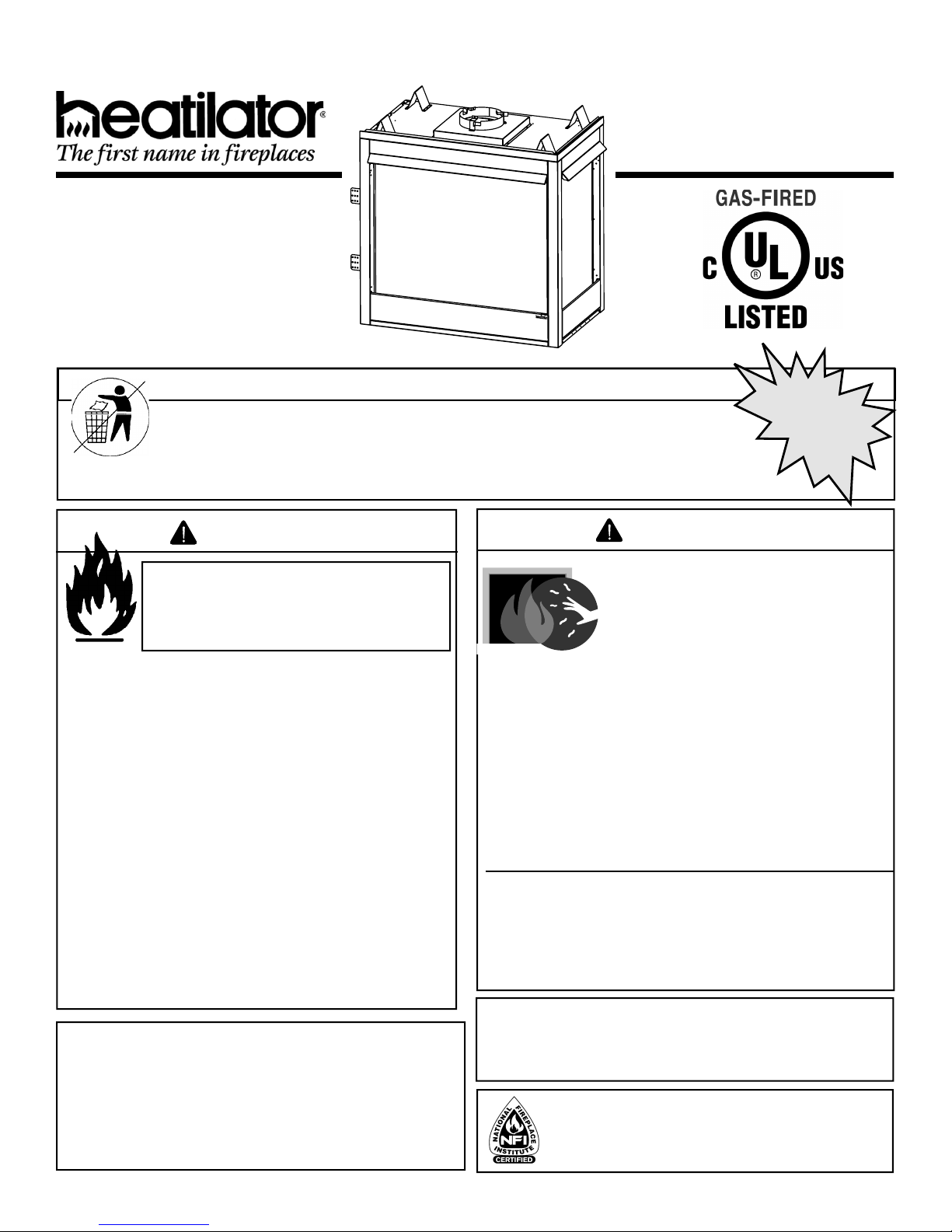
Heatilator GBST36, GBFL36, GBCR36, GBCL36 Owner's Manual
Models:
GBST36 Series
GBFL36 Series
GBCR36 Series
GBCL36 Series
B-Vent Gas Appliance
Owner’s Manual
Installation and Operation
(GBFL36 Shown)
CAUTION
DO NOT DISCARD THIS MANUAL
•
• Important operating and
maintenance instructions
included.
Read, understand and follow
these instructions for safe
installation and operation.
WARNING
If the information in these instructions is not followed exactly, a
fi re may result causing property
damage, personal injury, or death.
• Do not store or use gasoline or other fl am-
mable vapors and liquids in the vicinity of
this or any other appliance.
• What to do if you smell gas:
- Do not try to light any appliance.
- Do not touch any electrical switch. Do not
use any phone in your building.
- Immediately call your gas supplier from
a neighbor’s phone. Follow the gas
supplier’s instructions.
- If you cannot reach your gas supplier, call
the fi re department.
• Installation and service must be performed
by a qualifi ed installer, service agency, or
the gas supplier.
This appliance may be installed as an OEM installation
in manufactured home (USA only) or mobile home and
must be installed in accordance with the manufacturer’s
instructions and the manufactured home construction and
safety standard, Title 24 CFR, Part 3280 or Standard for
Installation in Mobile Homes, CAN/CSA Z240MH.
This appliance is only for use with the type(s) of gas
indicated on the rating plate.
DO NOT
DISCARD
•
Leave this manual with
party responsible for
use and operation.
WARNING
HOT SURFACES!
Glass and other surfaces are hot during
operation and cool down.
Hot glass will cause burns.
• Do not touch glass until it is cooled
• NEVER allow children to touch glass
• Keep children away
• CAREFULLY SUPERVISE children in same room as
appliance.
• Alert children and adults to hazards of high
temperatures.
High temperatures may ignite clothing or other
fl ammable materials.
• Keep clothing, furniture, draperies and other combustibles
away.
This appliance has been supplied with an integral
barrier to prevent direct contact with the fi xed glass
panel. Do NOT operate the appliance with the barrier
removed.
Contact your dealer or Hearth & Home Technologies if the
barrier is not present or help is needed to properly install one.
In the Commonwealth of Massachusetts installation must
be performed by a licensed plumber or gas fi tter;
See Table of Contents for location of additional
Commonwealth of Massachusetts requirements.
Installation and service of this appliance should be performed
by qualifi ed personnel. Hearth & Home Technologies suggests
NFI certifi ed or factory-trained professionals, or technicians
supervised by an NFI certifi ed professional.
¨
¨
Heatilator • Caliber Multi-Sided B-Vent • 4002-094 Rev H • 11/07 1
Read this manual before installing or operating this appliance.
Please retain this owner’s manual for future reference.
Congratulations
Congratulations on selecting a Heatilator gas appliance—an
elegant and clean alternative to wood burning appliances.
The Heatilator gas appliance you have selected is designed
to provide the utmost in safety, reliability, and effi ciency.
As the owner of a new appliance, you’ll want to read and
carefully follow all of the instructions contained in this owner’s
The information contained in this owner’s manual, unless
noted otherwise, applies to all models and gas control
systems.
Your new Heatilator gas appliance will give you years of
durable use and trouble-free enjoyment. Welcome to the
Heatilator family of appliance products!
manual. Pay special attention to all cautions and warnings.
This owner’s manual should be retained for future reference.
We suggest you keep it with your other important documents
and product manuals.
We recommend that you record the following pertinent
Homeowner Reference Information
information about your appliance:
Model Name: Date purchased/installed:
Serial Number: Location on appliance:
Dealership purchased from: Dealer phone:
Notes:
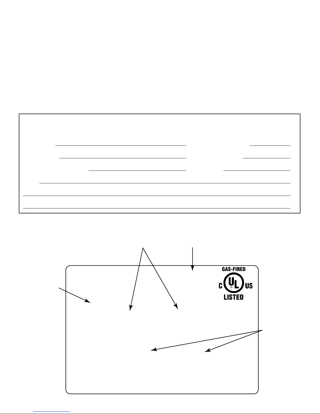
Listing Label Information/Location
The model information regarding your specifi c appliance can be found on the rating plate located in the control area of the
appliance.
Serial #
XXXXXXXXX
XXXX
CERTIFIED
FOR CANADA
CERTIFIÉ POUR LE
CANADA
Orifice
Size
Model #
Gas Type
Hearth & Home Technologies Inc
1915 W. Saunders Street
Mt. Pleasant, IA 52641
ANSI Standard
MODEL MFG. DATE
MODÈLE DATE DE FAB.
GAS TYPE/TYPE DE GAZ NATURAL/NATUREL PROPANE
ALTITUDE 0-2000 2000-4000 FT/PI 0-2000 2000-4000 FT/PI
MAX INPUT/DÉBIT XX,XXX XX,XXX BTUH XX,XXX XX,XXX BTUH
MIN INPUT/DÉBIT XX,XXX XX,XXX BTUH XX,XXX XX,XXX BTUH
MANIFOLD PRESSURE/PRESSION TUBULAIRE
MAX. XX IN. W.C./C. D'EAU XX IN. W.C./C. D'EAU
MIN. XX IN. W.C./C. D'EAU XX IN. W.C./C. D'EAU
MIN. INLET PRESS. XX IN. W.C./C. D'EAU 1XX IN. W.C./C. D'EAU
FOR THE PURPOSE OF INPUT ADJUSTMENT
PRESS. MIN. D'ALIMENTATION
ORIFICE SIZE
DIAM. DE L'INJECTEUR XX/XX DIA. in./mm XX/XX DIA. in./mm
XXXXXX
SERIAL
NO. DE SÉRIE
LESS THAN/MOINS DE 3 AMPÈRES., 115V., 60 Hz
DO NOT REMOVE OR COVER THIS LABEL.
VENTED GAS FIREPLACE - NOT FOR USE WITH SOLID FUEL.
FOYER À GAZ À ÉVACUATION - NE DOIT PAS ÊTRE UTILISÉ
AVEC UN COMBUSTIBLE SOLIDE.
2 Heatilator • Caliber Multi-Sided B-Vent • 4002-094 Rev H • 11/07

Table of Contents
1 Listing and Code Approvals 4
A. Appliance Certifi cation . . . . . . . . . . . . . . . . . . . . . . . . . 4
B. Glass Specifi cations . . . . . . . . . . . . . . . . . . . . . . . . . . 4
C. BTU Specifi cations . . . . . . . . . . . . . . . . . . . . . . . . . . . 4
D. High Altitude Installations . . . . . . . . . . . . . . . . . . . . . . 4
E. Non-Combustible Materials . . . . . . . . . . . . . . . . . . . . . 4
F. Combustible Materials . . . . . . . . . . . . . . . . . . . . . . . . . 4
2 Getting Started 5
A. Design and Installation Considerations . . . . . . . . . . . . 5
B. Negative Pressure . . . . . . . . . . . . . . . . . . . . . . . . . . . . 6
C. Tools and Supplies Needed . . . . . . . . . . . . . . . . . . . . . 7
D. Inspect the Appliance and Components . . . . . . . . . . . 7
3 Framing and Clearances 8
A. Select Appliance Location . . . . . . . . . . . . . . . . . . . . . . 8
B. Construct the Appliance Chase . . . . . . . . . . . . . . . . . . 9
C. Clearances . . . . . . . . . . . . . . . . . . . . . . . . . . . . . . . . 10
D. Mantel Projections . . . . . . . . . . . . . . . . . . . . . . . . . . . 10
4 Termination Locations 11
A. Vent Termination Minimum Clearances . . . . . . . . . . . 11
5 Vent Information and Diagrams 12
A. Vent Guidelines . . . . . . . . . . . . . . . . . . . . . . . . . . . . . 12
B. Vent System Confi guration . . . . . . . . . . . . . . . . . . . . .12
6 Vent Clearances and Framing 14
A. Pipe Clearances to Combustibles . . . . . . . . . . . . . . . 14
B. Wall Penetration Framing . . . . . . . . . . . . . . . . . . . . . 14
C. Vertical Penetration Framing . . . . . . . . . . . . . . . . . . . 14
7 Appliance Preparation 15
A. Installing Outside Air Kit Damper Assembly . . . . . . . 15
B. Gas and Electrical Connections . . . . . . . . . . . . . . . . 17
C. Securing and Leveling Appliance . . . . . . . . . . . . . . . 17
8 Installing Vent Pipe 18
A. Assemble Vent Sections . . . . . . . . . . . . . . . . . . . . . . 18
B. Attach Vent to Firebox Assembly . . . . . . . . . . . . . . . 18
C. Securing Vent Sections . . . . . . . . . . . . . . . . . . . . . . . 18
9 Gas Information 19
A. Fuel Conversion . . . . . . . . . . . . . . . . . . . . . . . . . . . . 19
B. Gas Pressure. . . . . . . . . . . . . . . . . . . . . . . . . . . . . . . 19
C. Gas Connection . . . . . . . . . . . . . . . . . . . . . . . . . . . . . 19
D. High Altitude Installations . . . . . . . . . . . . . . . . . . . . . 20
10 Electrical Information 21
A. Recommendation for Wire . . . . . . . . . . . . . . . . . . . . . 21
B. Connecting to the Appliance . . . . . . . . . . . . . . . . . . . 21
C. Intellifi re Ignition System Wiring . . . . . . . . . . . . . . . .21
D. Standing Pilot Ignition System Wiring . . . . . . . . . . . . 22
E. Install the Junction Box . . . . . . . . . . . . . . . . . . . . . . . 23
11 Finishing 24
A. Mantel Projections . . . . . . . . . . . . . . . . . . . . . . . . . . . 24
B. Facing Material . . . . . . . . . . . . . . . . . . . . . . . . . . . . . 24
12 Appliance Setup 25
A. Remove the Shipping Materials. . . . . . . . . . . . . . . . . 25
B. Clean the Appliance. . . . . . . . . . . . . . . . . . . . . . . . . . 25
C. Accessories . . . . . . . . . . . . . . . . . . . . . . . . . . . . . . . . 25
D. Lava Rock, Vermiculite, Rockwool Placement . . . . . 25
E. Log Assembly . . . . . . . . . . . . . . . . . . . . . . . . . . . . . . 25
F. Firescreen . . . . . . . . . . . . . . . . . . . . . . . . . . . . . . . . . 25
G. Glass Assembly . . . . . . . . . . . . . . . . . . . . . . . . . . . . . 26
H. Grilles and Trim . . . . . . . . . . . . . . . . . . . . . . . . . . . . . 26
I. Hood . . . . . . . . . . . . . . . . . . . . . . . . . . . . . . . . . . . . . 26
J. Air Shutter Setting . . . . . . . . . . . . . . . . . . . . . . . . . . .26
13 Operating Instructions 27
A. Before Lighting Appliance . . . . . . . . . . . . . . . . . . . . . 27
B. Check Appliance Draft . . . . . . . . . . . . . . . . . . . . . . . . 28
C. Lighting the Appliance . . . . . . . . . . . . . . . . . . . . . . . . 29
D. After the Appliance is Lit . . . . . . . . . . . . . . . . . . . . . . 31
E. Frequently Asked Questions . . . . . . . . . . . . . . . . . . . 31
14 Troubleshooting 32
A. Standing Pilot Ignition System . . . . . . . . . . . . . . . . . . 32
B. Intellifi re Ignition System . . . . . . . . . . . . . . . . . . . . . . 34
15 Maintaining and Servicing the Appliance 36
16 Reference Materials 38
A. Appliance Dimension Diagram . . . . . . . . . . . . . . . . . 38
B. Service Parts List. . . . . . . . . . . . . . . . . . . . . . . . . . . . 40
C. Optional Components . . . . . . . . . . . . . . . . . . . . . . . . 56
D. Limited Lifetime Warranty . . . . . . . . . . . . . . . . . . . . . 59
E. Contact Information . . . . . . . . . . . . . . . . . . . . . . . . . . 60
Note: An arrow (¨) found in the text signifi es change in
content.
Heatilator • Caliber Multi-Sided B-Vent • 4002-094 Rev H • 11/07 3
1
Listing and Code Approvals
1
A. Appliance Certifi cation
MODELS: GBST36 Series, GBFL36 Series, GBCR36
Series, GBCL36 Series, GBIS36 Series
LABORATORY: Underwriters Laboratories, Inc. (UL)
TYPE: B-Vent Gas Appliance
STANDARD: ANSI Z21.50b-2005/CSA2.22b-2005
This product is listed to ANSI standards for “Vented Gas
Fireplaces” and “Gas Fired Appliances for Use at High
Altitudes”.
This model (natural gas and propane) can be installed in a
bedroom (in the United States) which has a total volume of
unconfi ned space appropriate to the particular installation.
Refer to the National Fuel Gas Code ANSI Z223.1/NFPA54
(current edition), The Uniform Mechanical Code - (current
edition), and local building offi cials for the options allowed
in obtaining an effective bedroom volume of unconfi ned
space.
This model (natural gas and propane) can be installed in
a bedroom (in Canada) if a thermostat is installed with the
appliance. Consult local code authorities.
NOT INTENDED FOR USE AS A PRIMARY HEAT
SOURCE. This appliance is tested and approved as either
supplemental room heat or as a decorative appliance. It
should not be factored as primary heat in residential heating
calculations.
B. Glass Specifi cations
Hearth & Home Technologies appliances manufactured with
tempered glass may be installed in hazardous locations such
as bathtub enclosures as defi ned by the Consumer Product
Safety Commission (CPSC). The tempered glass has been
tested and certifi ed to the requirements of ANSI Z97.1 and
CPSC 16 CFR 1202 (Safety Glazing Certifi cation Council
SGCC# 1595 and 1597. Architectural Testing, Inc. Reports
02-31919.01 and 02-31917.01).
This statement is in compliance with CPSC 16 CFR Section
1201.5 “Certifi cation and labeling requirements” which refers
to 15 U.S. Code (USC) 2063 stating “…Such certifi cate shall
accompany the product or shall otherwise be furnished to
any distributor or retailer to whom the product is delivered.”
Some local building codes require the use of tempered glass
with permanent marking in such locations. Glass meeting
this requirement is available from the factory. Please contact
your dealer or distributor to order.
Note: This installation must conform with local codes. In the
absence of local codes you must comply with the National
Fuel Gas Code, ANSI Z223.1-latest edition in the U.S.A.
and the CAN/CGA B149 Installation Codes in Canada.
C. BTU Specifi cations
Caliber Multi-sided BV
Standing Pilot
Max/Min Input Rate (NG) 34,000/21,000
Orifi ce Size (NG) .115 in./2.92 mm
Max/Min Input Rate (LP) 30,000/21,000
Orifi ce Size (LP) .067 in./1.70 mm
IPI
Max/Min Input Rate (NG) 34,000/25,000
Orifi ce Size (NG) .115 in./2.92 mm
Max/Min Input Rate (LP) 30,000//22,000
Orifi ce Size (LP) .063 in./1.60 mm
D. High Altitude Installations
U.L. Listed gas appliances are tested and approved without
requiring changes for elevations from 0 to 2000 feet in the
U.S.A. and Canada.
When installing this appliance at an elevation above 2000 ft,
it may be necessary to decrease the input rating by changing the existing burner orifi ce to a smaller size. Input rate
should be reduced by 4% for each 1000 ft above a 2000 ft
elevation in the U.S.A., or 10% for elevations between 2000
and 4500 ft in Canada. If the heating value of the gas has
been reduced, these rules do not apply. To identify the proper orifi ce size, check with the local gas utility.
If installing this appliance at an elevation above 4500 ft (in
Canada), check with local authorities.
E. Non-Combustible Materials
Material which will not ignite and burn. Such materials are
those consisting entirely of steel, iron, brick, tile, concrete,
slate, glass or plasters, or any combination thereof.
Materials that are reported as passing ASTM E 136, Stan-
dard Test Method for Behavior of Materials in a Vertical
Tube Furnace at 750° C, shall be considered non-combus-
tible materials.
F. Combustible Materials
Materials made of or surfaced with wood, compressed paper, plant fi bers, plastics, or other material that can ignite and
burn, whether fl ame proofed or not, or whether plastered or
unplastered shall be considered combustible materials.
WARNING
Do NOT use this appliance if any part has been under
water. Immediately call a qualifi ed service technician
to inspect the appliance and to replace any part of the
control system and any gas control which has been
under water.
4 Heatilator • Caliber Multi-Sided B-Vent • 4002-094 Rev H • 11/07
2
Getting Started
2
A. Design and Installation Considerations
Heatilator B-vent gas appliances are designed to operate
with all exhaust gases expelled to the outside of the building,
and combustion air pulled from the room.
CAUTION
Check building codes prior to installation.
• Installation MUST comply with local, regional,
state and national codes and regulations.
• Consult insurance carrier, local building, fire
offi cials or authorities having jurisdiction about
restrictions, installation inspection, and permits.
When planning an appliance installation, it’s necessary to
determine the following information before installing:
• Where the appliance is to be installed. See Sections 3
and 4.
• The vent system confi guration to be used. See Sections
5 and 6.
• Gas supply piping. See Sections 7 and 9.
• Electrical wiring. See Sections 7 and 10
• Framing and finishing details. See Sections 3, 6
and 11.
• Whether optional accessories—devices such as a fan, wall
switch, or remote control—are desired. See Section 10.
WARNING
Keep appliance dry.
• Mold or rust may cause
odors.
• Water may damage controls.
Heatilator • Caliber Multi-Sided B-Vent • 4002-094 Rev H • 11/07 5
B. Negative Pressure
WARNING
Asphyxiation Risk
• Negative pressure can cause spillage of
combustion fumes and soot.
• Fire needs to draft properly for safe
operation.
Draft is the pressure difference needed to vent fi replaces
successfully. Considerations for successful draft include:
• Preventing negative pressure.
• Location of fi replace and chimney.
Negative Pressure
Negative pressure results from the imbalance of air available for the fi replace to operate properly. Causes for this
imbalance include:
• Exhaust fans (kitchen, bath, etc.).
• Range hoods.
• Combustion air requirements for furnaces, water heaters
and other combustion appliances.
• Clothes dryers.
• Location of return-air vents to furnace or air
conditioning.
• Imbalances of the HVAC air handling system.
• Upper level air leaks (recessed lighting, attic hatch
opening, duct leaks).
To minimize the effects of negative air pressure, the following must be considered:
• Install the outside air kit. Install the intake on the side of
the house towards prevailing winds during the heating
season.
• Ensure adequate outdoor air is supplied for combustion
appliances and exhaust equipment.
• Ensure furnace and air conditioning return vents are not
located in the immediate vicinity of the fi replace.
• Avoid installing the fi replace near doors, walkways or small
isolated spaces.
• Recessed lighting should be a “sealed can” design; attic
hatches weather stripped or sealed; attic mounted duct
work and air handler joints and seams taped or sealed.
• Basement installations should be avoided due to stack
effect. Stack effect creates negative pressure in lower
levels. Hearth & Home Technologies recommends the
use of direct vent fi replaces in basements.
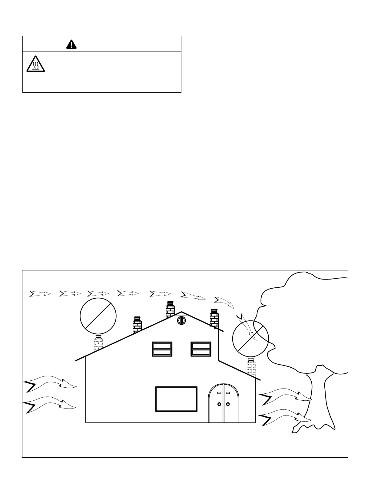
Location of the fi replace and chimney will affect performance.
As shown in Figure 2.1 the chimney should:
• Be installed through the warm airspace enclosed by the
building envelope. This helps to produce more draft,
especially during lighting and die-down of the fi re.
• Penetrate the highest part of the roof. This minimizes the
effects of wind turbulence.
• Be located away from trees, adjacent structures, uneven
roof lines and other obstructions.
Offsets can restrict draft so their use should be minimized.
Consider the fi replace location relative to fl oor and ceiling
and attic joists.
Location
Not
Recommended
Windward
Figure 2.1 Recommended Chimney Locations
Marginal
Location
Recommended
Location
Multi-level Roofs
Recommended
Location
Location
Not
Recommended
Leeward
6 Heatilator • Caliber Multi-Sided B-Vent • 4002-094 Rev H • 11/07
C. Tools and Supplies Needed
Before beginning the installation be sure that the following
tools and building supplies are available.
Reciprocating saw Framing material
Pliers Hi temp caulking material
Hammer Gloves
Phillips screwdriver Framing square
Flat blade screwdriver Electric drill and bits (1/4 in.)
Plumb line Safety glasses
Level Manometer
Voltmeter Tape measure
Non-corrosive leak check solution
1/2 - 3/4 in. length, #6 or #8 Self-drilling screws
One 1/4 in. female connection (for optional fan).
D. Inspect the Appliance and Components
WARNING
Inspect appliance and components for
damage. Damaged parts may impair safe
operation.
• Do NOT install damaged components.
• Do NOT install incomplete components.
• Do NOT install substitute components.
Report damaged parts to dealer.
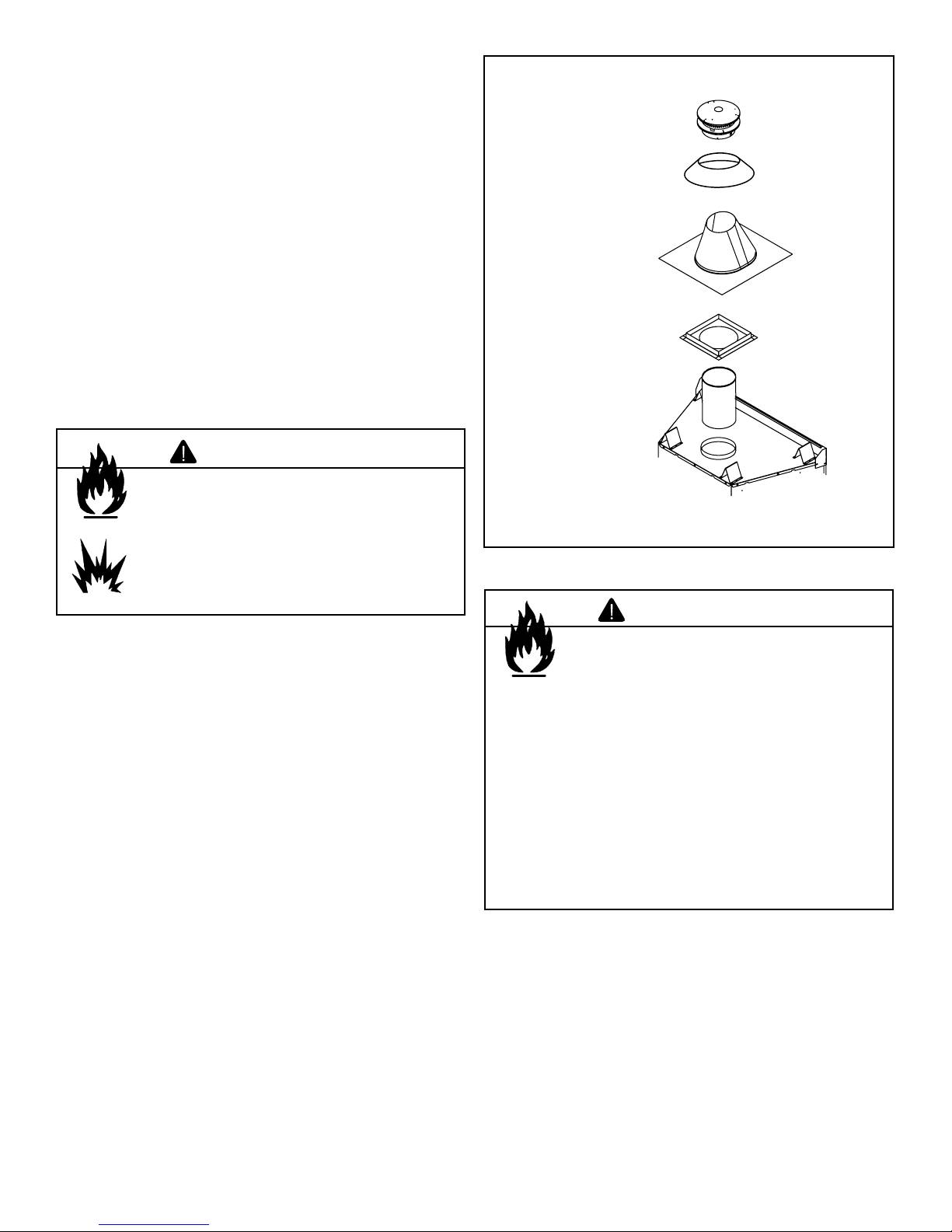
The following B-vent components are needed for installation. See Figure 2.2.
• Appliance
• Pipe components
• Firestops
• Elbows
• Strapping
• Roof fl ashing or chase top
• Termination cap
• Storm Collar
• Carefully remove the appliance and components from the
packaging.
• The vent system components and trim doors are shipped
in separate packages.
• The gas logs may be packaged separately and must be
fi eld installed.
• Report to your dealer any parts damaged in shipment,
particularly the condition of the glass.
• Read all of the instructions before starting the
installation. Follow these instructions carefully
during the installation to ensure maximum safety and
benefi t.
Vertical
Termination
Cap
Storm
Collar
Roof
Flashing
Ceiling
Firestop
B-Vent Pipe
Sections
Figure 2.2 Typical Vertical Installation
WARNING
Hearth & Home Technologies disclaims any
responsibility for, and the warranty will be
voided by, the following actions:
• Installation and use of any damaged appliance or
vent system component.
• Modifi cation of the appliance or vent system.
• Installation other than as instructed by Hearth & Home
Technologies.
• Improper positioning of the gas logs or the glass
door.
• Installation and/or use of any component part not
approved by Hearth & Home Technologies.
Any such action may cause a fi re hazard.
Heatilator • Caliber Multi-Sided B-Vent • 4002-094 Rev H • 11/07 7
3
Framing and Clearances
3
Note:
• Illustrations refl ect typical installations and are FOR
DESIGN PURPOSES ONLY.
• Illustrations/diagrams are not drawn to scale.
• Actual installation may vary due to individual design
preference.
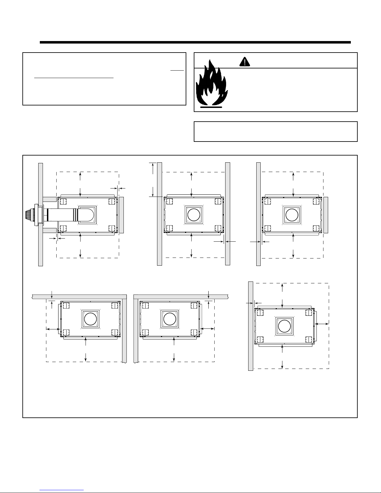
A. Select Appliance Location
When selecting a location for your appliance it is important to
consider the required clearances to walls (See Figure 3.1).
48 in.
* 36 in.
(914 mm)
1/2 in.
(13 mm)
(219 mm)
maximum
WARNING
Fire Risk
Provide adequate clearance:
• Around air openings.
• For service access.
Locate appliance away from traffi c areas.
Note: For actual appliance dimensions refer to
Section 16.
* 36 in.
(914 mm)
* 36 in.
(914 mm)
1/2 in.
(13 mm)
1/2 in.
(13 mm)
* 12 in.
(305 mm)
Figure 3.1 Appliance Locations
* 36 in.
(914 mm)
* 36 in.
(914 mm)
GBCL36
* 36 in.
(914 mm)
GBST36
1/2 in.
(13 mm)
(305 mm)
* 36 in.
(914 mm)
GBCR36
1/2 in.
(13 mm)
1/2 in.
(13 mm)
* 12 in.
* NO combustible objects within this area!
* 36 in.
(914 mm)
* 36 in.
(914 mm)
* 12 in.
(305 mm)
* 36 in.
(914 mm)
GBFL36
8 Heatilator • Caliber Multi-Sided B-Vent • 4002-094 Rev H • 11/07

B. Construct the Appliance Chase
A chase is a vertical boxlike structure built to enclose the gas
appliance and/or its vent system. Vertical vents that run on
the outside of a building may be, but are not required to be,
installed inside a chase.
Construction of the chase may vary with the type of building. These instructions are not substitutes for the requirements of local building codes. Local building codes MUST
be checked.
Chases should be constructed in the manner of all outside
walls of the home to prevent cold air drafting problems. The
chase should not break the outside building envelope in any
manner.
Walls, ceiling, base plate and cantilever fl oor of the chase
should be insulated. Vapor and air infi ltration barriers should
be installed in the chase as per regional codes for the rest of
the home. Additionally, Hearth & Home Technologies recommends that the inside surfaces be sheetrocked and taped
(or the use of an equivalent method) for maximum air tightness.
To further prevent drafts, gas line holes and other openings
should be caulked with high temperature caulk or stuffed
with unfaced insulation. If the appliance is being installed
on a cement slab, we recommend that a layer of plywood
be placed underneath to prevent conducting cold up into the
room.
WARNING
Fire Risk
• Construct chase to all clearance
specifi cations in manual.
• Locate and install appliance to all
clearance specifi cations in manual.
WARNING
Fire Risk
Odor Risk
• Install appliance on hard metal or wood
surfaces extending full width and depth
of appliance.
• Do NOT install appliance directly on
carpeting, vinyl, tile or any combustible
material other than wood.
• Do NOT place furniture or any other
combustible household objects within
36 in. of the appliance front.
Heatilator • Caliber Multi-Sided B-Vent • 4002-094 Rev H • 11/07 9
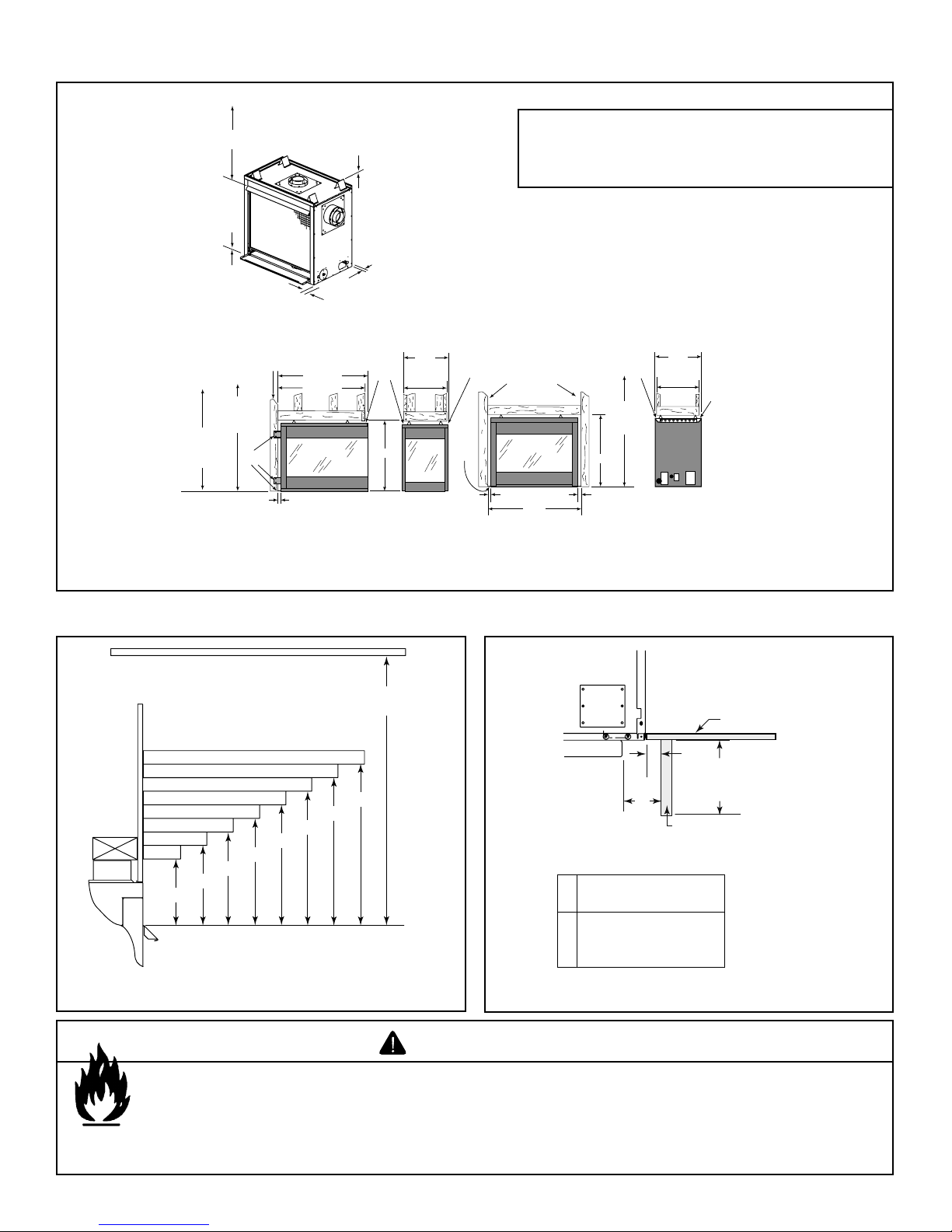
C. Clearances
34-3/8 in. (762 mm)
to ceiling
0 in.
TO FLOOR
1/2 in. (13 mm) to unfinished
(Except for the CH Series)
Long side of
framing to front.
47 in. min.
window
placement
42 in. min.
mantel
placement
NAILING
FLANGES
1/2 in.
*
This dimension does not include
the thickness of the drywall.
Figure 3.2 Clearances to Combustibles
side of appliance
40-1/2 in.
*
39-7/8 in.
GBFL36 SERIES
0 in. TO LEVEL
OF STANDOFFS
1/2 in. (13 mm) to
unfinis
hed back
of appliance
(CL, CR and CH Series
appliances ONLY)
5/8 in.
24 in.
drywall
lip
22-3/4 in.
41 in.
*
5/8 in.
drywall
NAILING
FLANGES
Note: If the i n side of the framed cavity is to b e fi nished,
the framing dimensions must include the fi nished
sur fac e. If dry wall i s t o be at t a c h e d to the rear wal l , the
depth must be measured from the drywall surface.
Long side
lip
of framing
to the front
1/2 in. 1/2 in.
41 in.
Note: The GBCL/CR36 and GBIS36 Series
use the same framing dimensions.
47 in. min.
window
placement
41 in.
GBST36 SERIES
5/8 in.
drywall
lip
24 in.
22-3/4 in.
*
5/8 in.
drywall
lip
D. Mantel Projections
34-3/8 in. minimum
to ceiling
18
17
16
1-11
12
13
15
14
8-1/2
7-3/4
7
10
9-1/4
6-1/4
5-1/2
4-3/4
Measured from top of hood (in inches)
Figure 3.3 Clearances to Mantels or Other Combustibles Above
Appliance
WARNING
Top of
Appliance
Drywall
A
48 in.
(1219 mm)
B
max.
Mantel Leg or
Perpendicular Wall
0 in. min.
A
to perpendicular wall
2 in. (51 mm) min.
B
from fireplace opening
to perpendicular wall
Figure 3.4 Clearances to Combustible Mantel Legs or Wall Projec-
¨
tions (acceptable on both sides of opening)
Fire Risk
• Comply with all minimum clearances to combustibles as specifi ed.
• Framing or fi nishing material used on the front of, or in front of, the appliance closer than the minimums
listed, must be constructed entirely of noncombustible materials (i.e., steel studs, concrete board, etc.).
Failure to comply may cause fi re.
10 Heatilator • Caliber Multi-Sided B-Vent • 4002-094 Rev H • 11/07
4
Termination Locations
4
A. Vent Termination Minimum Clearances
WARNING
Fire Risk
Explosion Risk
Maintain vent clearance to combustibles as
specifi ed.
• Do not pack air space with insulation or
other materials.
Failure to keep insulation or other materials
away from vent pipe may cause fi re.
8 ft
Termination
Cap
Storm Collar
Roof
Flashing
(2.44 m)
Lowest
Discharge
Opening
12
Vertical
wall
X
Roof Pitch
is X / 12
B-Vent Gas, Wood or Fuel
Oil Termination
8 ft
18 in.
(457 mm)
Gas
Termination
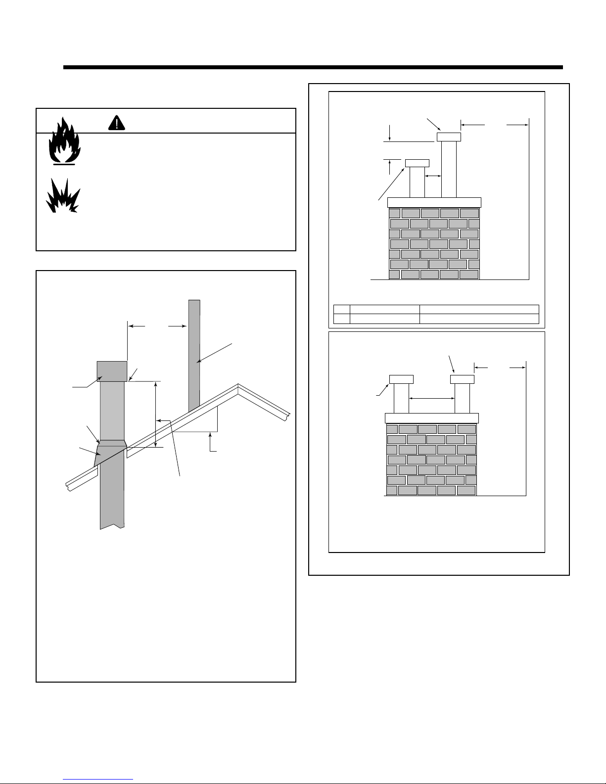
Termination Caps Staggered Height
A Gas Termination Wood or Fuel Oil Termination
B 6 in.
Gas Termination
(152 mm) min. 20 in. (508 mm) min.
B-Vent Gas, Wood or Fuel
Oil Termination
Wood or
20 in. min. *
(508 mm)
A
B
(2.44 m)
(minimum) to
Perpendicular
Wall
(gas only)
8 ft
(2.44 m)
(minimum) to
Perpendicular
Wall
(gas only)
H (min.) - Minimum height
from roof to lowest
discharge opening.
* If using decorative cap cover(s), this distance may
need to be increased. Refer to the installation instruc tions supplied with the decorative cap cover.
Roof Pitch H (Min.) Ft. Roof Pitch H (Min.) Ft.
Flat to 6/12 1.0* Over 11/12 to 12/12 4.0
Over 6/12 to 7/12 1.25* Over 12/12 to 14/12 5.0
Over 7/12 to 8/12 1.5* Over 14/12 to 16/12 6.0
Over 8/12 to 9/12 2.0* Over 16/12 to 18/12 7.0
Over 9/12 to 10/12 2.5 Over 18/12 to 20/12 7.5
Over 10/12 to 11/12 3.25 Over 20/12 to 21/12 8.0
* 3 ft. minimum in snow regions
Figure 4.1
Heatilator • Caliber Multi-Sided B-Vent • 4002-094 Rev H • 11/07 11
Minimum Height from Roof to Lowest Discharge Opening
Figure 4.2 Multiple Vertical Termination
Termination Caps Same Height
5
Vent Information and Diagrams
5
A. Vent Guidelines
WARNING
Fire Risk
Asphyxiation Risk
This appliance requires the specifi ed pipe
for operation.
• Incorrect pipe may cause spillage,
condensation and overheating.
These models require the following size B-Vent double wall
vent pipe.
Model Pipe Size
GBFL36 Series
GBCR36 Series
GBCL36 Series
GBST36 Series
• Follow pipe manufacturer’s installation guidelines when
installing the appliance.
5 in./127 mm
B. Vent System Confi guration
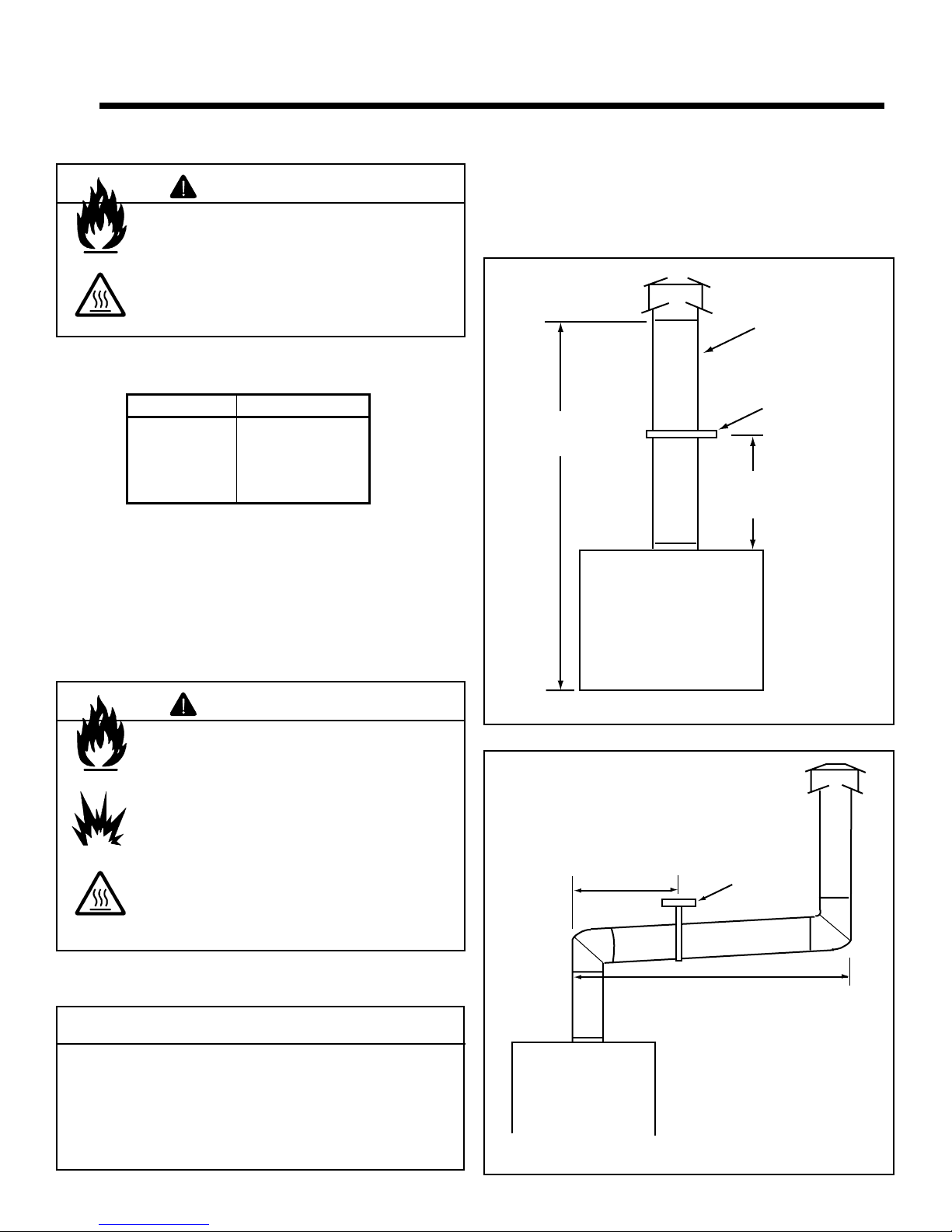
• Rise to Run Ration: 2:1
• Maximum Total Horizontal Run: 20 ft (6.1 m)
• Minimum Total Vertical Rise: 12 ft (3.66 m)
• Maximum Total Vertical Rise: 60 ft (18.29 m)
• Maximum Number of Elbows: Four 90° or Eight 45°
Minimum
clearances are
per vent
manufacturer's
specifications
Metal
plumber's strap
12 ft (3.66 m) min.
60 ft (18.29 m) max.
secured to
framing
Vent supports are per
vent manufacturer's
specifications
WARNING
Fire Risk
Explosion Risk
Asphyxiation Risk
Do NOT connect this gas appliance to a
chimney fl ue serving a separate solid-fuel
or gas burning appliance.
• Vent this appliance directly outside.
• Use separate vent system for this
appliance.
May impair safe operation of this appliance or
other appliances connected to the fl ue.
CAUTION
ALL vent configuration specifications MUST be
followed.
• This product is tested and listed to appliance and
vent manufacturer’s specifi cations.
• Appliance performance will suffer if specifi cations
are not followed.
Figure 5.1 Vertical Termination Clearances
Vent supports
are per vent
manufacturer’s
specifications.
Maximum horizontal run is 50% of
vertical. Horizontal run cannot be
more than 30 ft. (9.14 m).
¨
Figure 5.2 Maximum Horizontal Run
Metal
Plumbers'
Strap
12 Heatilator • Caliber Multi-Sided B-Vent • 4002-094 Rev H • 11/07
WARNING
Fire Risk
Explosion Risk
Insulation and other combustibles must not
infringe on clearances.
• ALWAYS maintain specifi ed clearances
around venting and fi restop systems.
• Install fi restops as specifi ed.
Failure to keep insulation or other material
away from vent pipe may cause fi re.
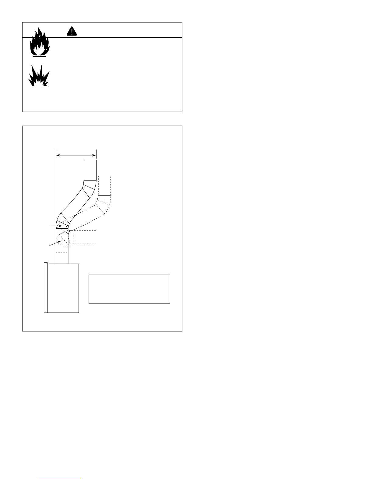
Maximum
horizontal
30 ft (9.14 m)
45°
Elbow
90°
Elbow
Figure 5.3 Maximum Horizontal Run
¨
Offsets exceeding
45° adapt horizontal
limitations
Note: Maximum horizontal
distance is 50% of vertical
vent height.
Heatilator • Caliber Multi-Sided B-Vent • 4002-094 Rev H • 11/07 13
6
Vent Clearances and Framing
6
A. Pipe Clearances to Combustibles
WARNING
Fire Risk
Explosion Risk
Maintain vent clearance to combustibles as
specifi ed.
• Do not pack air space with insulation or
other materials.
• National building codes recommend
using attic shield to keep loose materials/
insulation from contacting vent.
Failure to keep insulation or other materials
away from vent pipe may cause fi re.
Follow vent pipe manufacturer’s instructions for all clearances around pipe.
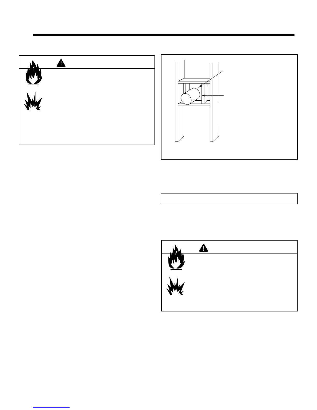
B. Wall Penetration Framing
Do not pack with insulation
or other materials.
Use manufacturer's
installation instructions for
framing dimensions
Figure 6.1 Exterior Wall Hole
For a wall penetration consult B-vent pipe manufacturer’s
instructions. Use same dimensional framing materials as
those used in the wall construction.
Note: MUST terminate vertically.
C. Vertical Penetration Framing
Use B-vent manufacturer’s fi restops to provide adequate
clearances.
WARNING
Fire Risk
Keep loose materials or blown insulation
from touching the vent pipe.
• National building codes recommend
using attic shield to keep loose materials/
insulation from contacting vent.
• Hearth & Home Technologies requires
the use of an attic shield.
14 Heatilator • Caliber Multi-Sided B-Vent • 4002-094 Rev H • 11/07
7
Appliance Preparation
7
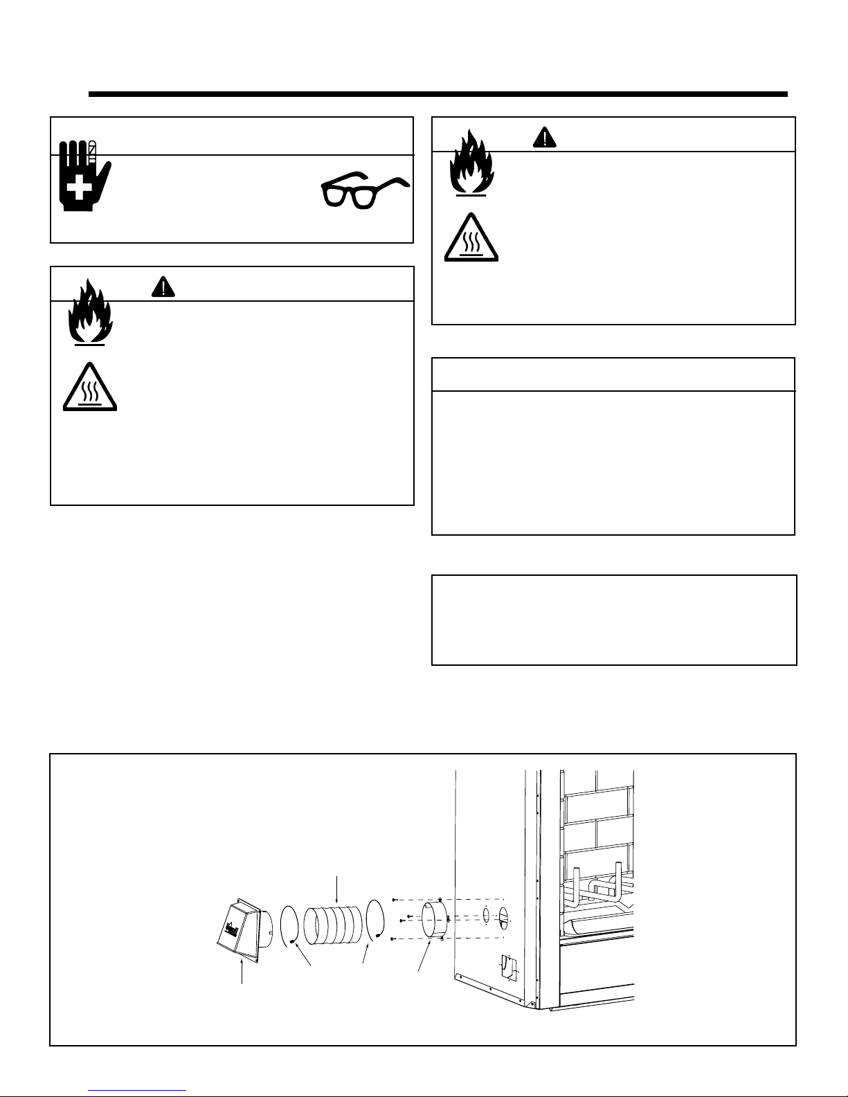
CAUTION
Sharp Edges
• Wear protective gloves
and safety glasses during
installation.
WARNING
Fire Risk
Asphyxiation Risk
Maintain vent clearance to combustibles as
specifi ed.
• Do not pack air space with insulation or
other materials.
• National building codes recommend
using attic shield to keep loose materials/
insulation from contacting vent.
Failure to keep insulation or other materials
away from vent pipe may cause fi re.
A. Installing Outside Air Kit Damper Assembly
This appliance will operate correctly only if adequate ventilation is provided to allow proper draft to the system.
An outside air kit is available as an optional feature with this
appliance. An outside air kit helps to decrease the amount
of room air taken by utilizing outside air for combustion. We
strongly recommend that it be installed.
• The outside air kit can only be installed on the left side of
the appliance.
• Refer to the installation instructions provided with the
kit.
WARNING
Fire Risk
Asphyxiation Risk
Do not draw outside combustion air from:.
• Wall, fl oor or ceiling cavity.
• Enclosed space such as an attic or
garage.
• Close proximity to exhaust vents or
chimneys.
Fumes or odor may result.
CAUTION
Risk of Smoke Spillage
Outside air inlet must be located to prevent blockage
from:
• Leaves
• Snow/ice
• Other debris
Blockage may cause combustion air starvation.
Note: The outside air kit inlet thimble should be positioned
in a manner that will not allow snow, leaves, etc. to block
the inlet. A 3 ft. (.91 m) minimum height difference must be
maintained from the top of the uppermost chimney section
to the outside combustion air inlet. Reference Section 2.
Outside
Air Shield
Figure 7.1 Outside Air Installation
Heatilator • Caliber Multi-Sided B-Vent • 4002-094 Rev H • 11/07 15
Flexible Duct
(not supplied)
2 Wire Ties
Outside
Air Collar
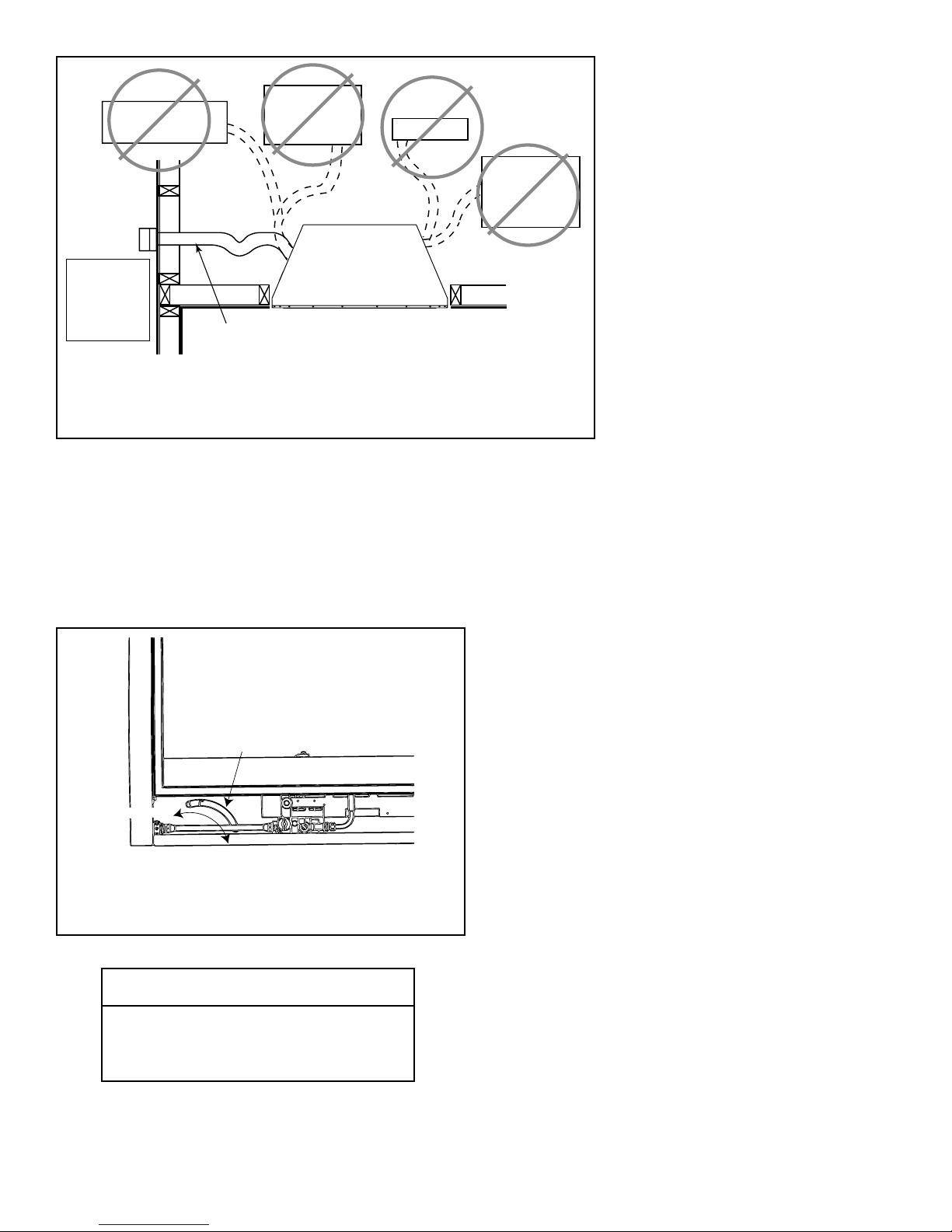
NO
Outlet blocked by
snow, leaves, etc.
NO
Garage or
combustible
liquids storage
NO
Attic space
NO
Outlet placed
higher than 3 ft
below the
termination cap
YES
Clear area
outside
house or in
ventilated
crawl space
Figure 7.2 Outside Combustion Air Placement
Use only duct materials specified
by manufacturer (preferably with
short run or mainly straight duct,
except small dip for cold air trap
which will help prevent flow of cold air).
Factory-built
fireplace
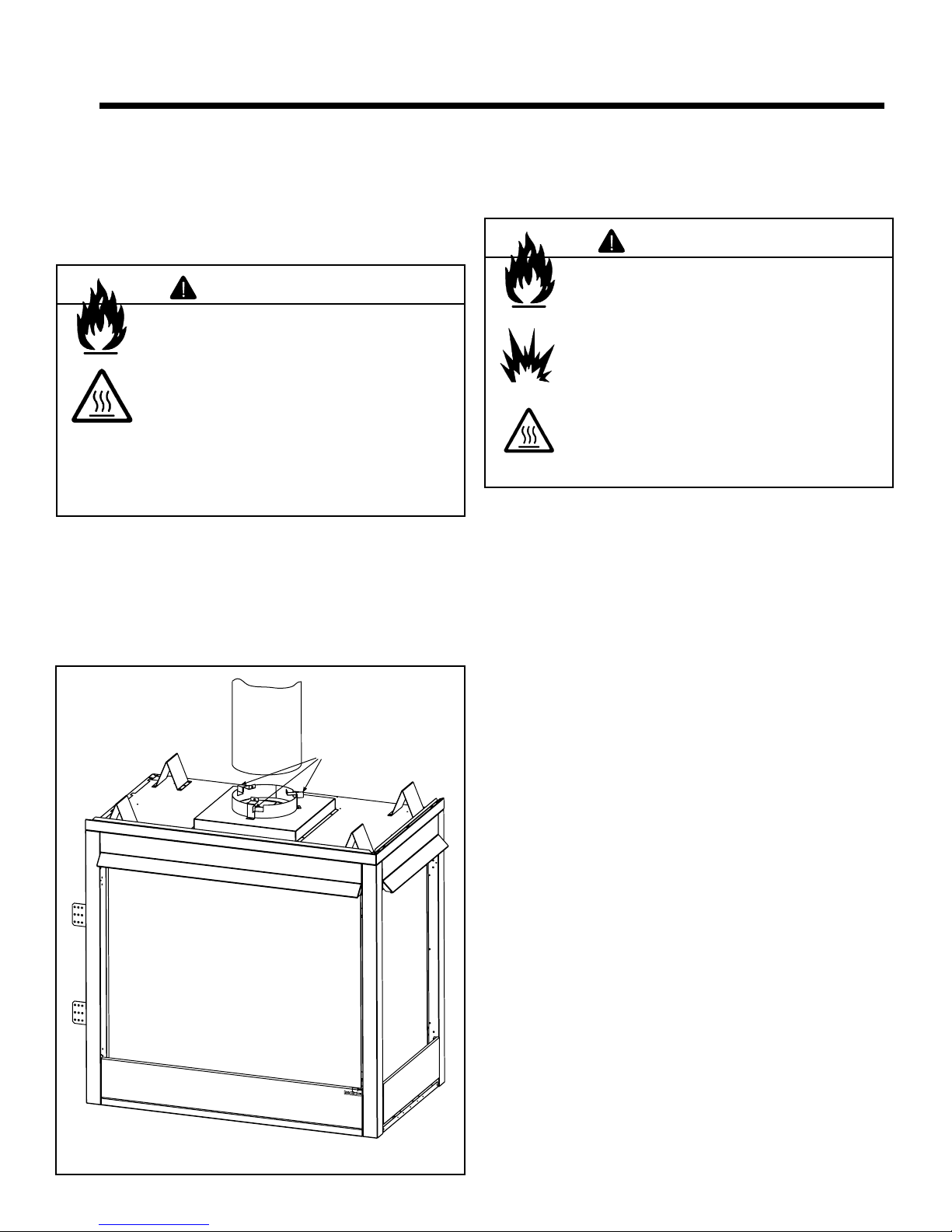
• Outside Air Kit Operations:
Before starting the appliance, open the control access
panel. Locate the outside air door handle. See Figure 7.3.
Rotate the handle to the “OPEN” position. When through
burning the appliance, open the control access panel,
grasp the handle and rotate to the “CLOSED” position.
OUTSIDE
AIR HANDLE
CLOSED
OPEN
Figure 7.3 Locating and Operating the AK14 Outside Air Kit
CAUTION
The air kit handle may get hot while burning
the appliance. Use care when operating
the handle.
16 Heatilator • Caliber Multi-Sided B-Vent • 4002-094 Rev H • 11/07
B. Gas and Electrical Connections
Ensure that gas and electrical connections are installed at
this time. Refer to Sections 9 and 10.
C. Securing and Leveling Appliance
WARNING
Fire Risk
• Prevent contact with sagging, loose
insulation.
• Do NOT install against vapor barriers or
exposed insulation.
The diagram shows how to properly position, level, and secure the appliance (see Figure 7.4). Nailing tabs are provided to secure the appliance to the framing members.
• Place the appliance into position.
• Level the appliance from side to side and front to back.
• Shim the appliance as necessary. It is acceptable to use
wood shims.
• Bend out nailing tabs on each side.
• Keep nailing tabs fl ush with the framing.
• Secure the appliance to the framing by using nails or
screws through the nailing tabs.
Note: Once appliance is set up for top or rear venting, it
CANNOT be changed at a later time.
CAUTION
Do NOT notch into the framing around the appliance
spacers.
Nailing Tabs
(both sides)
Figure 7.4 Proper Positioning, Leveling and Securing of an
Appliance
Heatilator • Caliber Multi-Sided B-Vent • 4002-094 Rev H • 11/07 17
8
Installing Vent Pipe
8
A. Assemble Vent Sections
This B-Vent appliance requires 5 in. B-vent double-wall pipe.
Follow the pipe manufacturer’s installation guidelines when
installing the appliance. This will ensure proper operation
and prevent safety hazards.
WARNING
Fire Risk
Exhaust Fumes Risk
Impaired Performance of Appliance.
• Assemble pipe sections per B-Vent
manufacturer’s instructions.
• Use support tabs for screws.
• Screws must not exceed 1 in. long and
must not penetrate inner lining.
• Pipe may separate if not properly
joined.
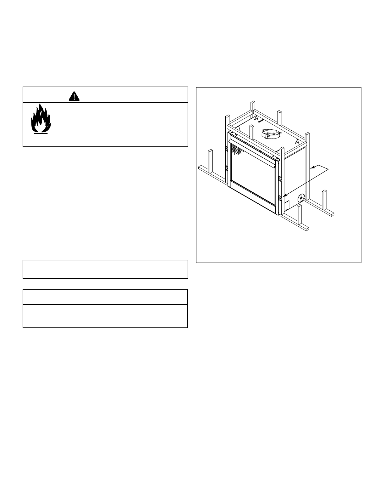
B. Attach Vent to Firebox Assembly
Three tabs extend from appliance collar shield. Attach tabs
to fi rst section of B-vent pipe using self-tapping 1/4 in. screws
supplied with appliance. See Figure 8.1.
C. Securing Vent Sections
Secure vent sections with vent supports following B-vent
manufacturer’s instructions.
WARNING
Fire Risk
Explosion Risk
Asphyxiation Risk
Use vent run supports per vent manufacturer’s
installation instructions.
Connect vent sections per vent manufacturer’s
installation instructions.
• Maintain all clearances to combustibles.
• Maintain specifi ed slope (if required).
Improper support may allow vent to sag or
separate.
Ta bs
Figure 8.1 Attaching Vent to Firebox
18 Heatilator • Caliber Multi-Sided B-Vent • 4002-094 Rev H • 11/07
 Loading...