

Heath Zenith SL-6133 Installation Manual
Wireless Add-on Switch
Model SL-6133
Your wireless add-on switch includes:
•1 transmitter wall switch unit
•1 receiver wall switch unit
•2 wire connectors
•2 #8 x 2" wood screws
Installation
1. Select a wall switch location that controls a light or overhead incandescent light.
Keep the following points in mind while selecting a location:
• Never install two receiver units within 3 feet (0.9 m) of each other or it could
reduce the operating range.
• The total lighting load must not exceed 500 watts (incandescent only).
• The receiver must be located within the range of the transmitter (up to 100
feet [30 m]) in the room or hallway that they are installed so they will operate
properly.
• Make sure that large metal objects are not located between the transmitter and
receiver since it could interfere with the signals.
2. Turn off the power to the light switch circuit before you proceed. Do this
at your circuit breaker or fuse box.
You'll need to buy a 9-volt alkaline battery for the wireless switch. In typical
use, this battery will last one year.
Multiple channels (A thru E) are available so that you can operate several
systems at different locations in your home. If you purchase more than one
system, make sure you select different operating channels, or they will interact with each other.
If you purchase a different switch plate to match your decor, make sure it is not a
metal plate. Metal wall plates will reduce the operating range.
© 2003 DESA Specialty Products™ 595-4918-05
IMPORTANT: Use only as a second switch to remotely control a light. Do
not use if more than one switch exists.
-2-
595-4918-05
3. Remove the existing switch plate and switch and disconnect its two wires.
Save the switch plate and screws to reinstall later.
If there are more than two wires attached to the switch, consult with an electrician
about installation. In addition, some local building codes may require installation
by a qualified electrician.
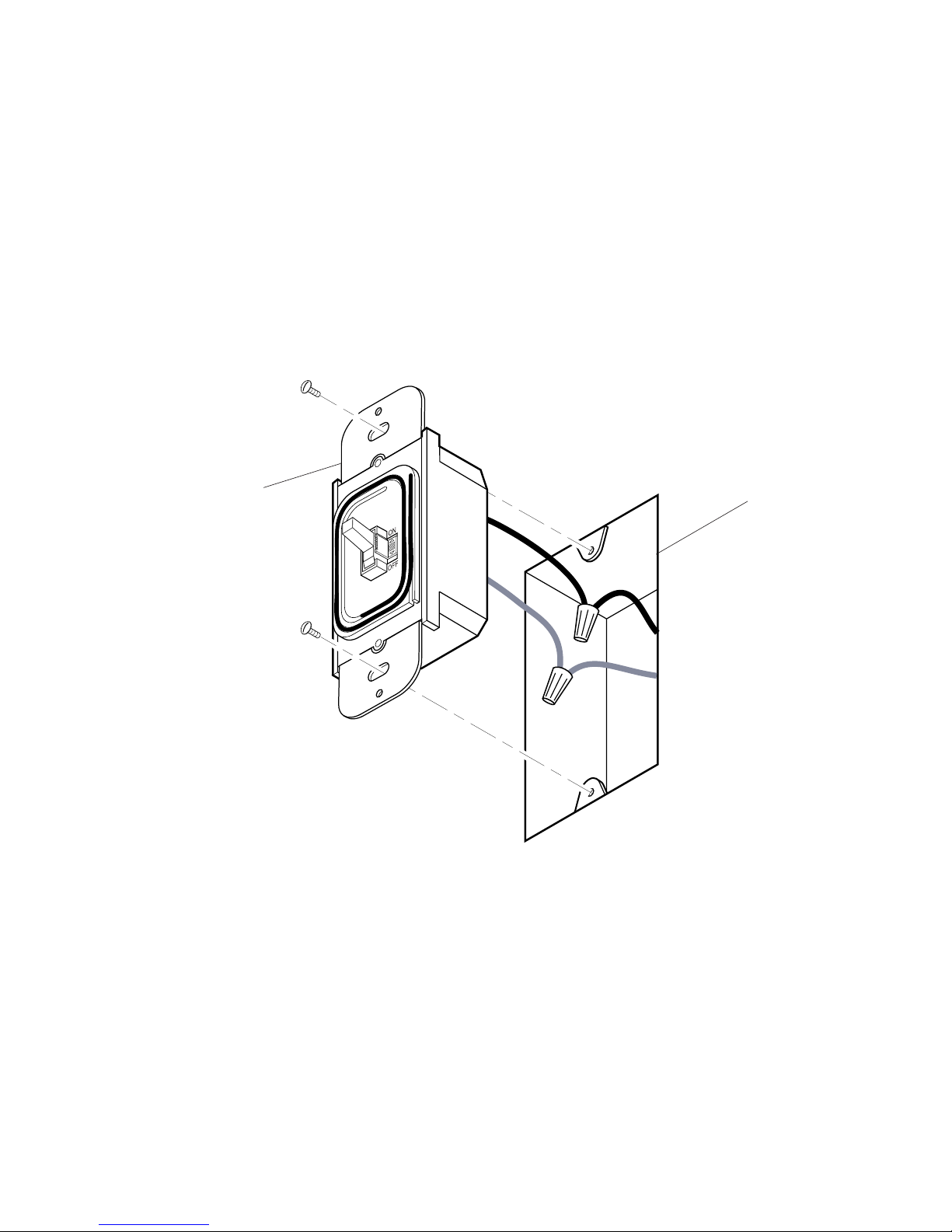
4. Connect a wire coming from the receiver to one wire you removed from
the switch. Use one of the supplied wire connectors to secure the wires
(see Figure 1).
5. Similarly connect the other wire coming from the receiver to the other wire you
removed from the switch. Secure the wires with a wire connector
6. Check your wire connections to make sure they are secure and that no bare
wires are exposed.
7. Position the receiver with the master switch to the right. Use the two screws
you removed earlier and mount the receiver to the wall box. Push the
excess wiring into the wall box while you do this. You may have to bend
the wires to fit inside the box. You will mount the switch plate later.
8. Turn on the power to the light switch circuit. Do this at your circuit breaker or
fuse box.
Figure 1 - Receiver Installation
Junction Box
Receiver
-3-
595-4918-05
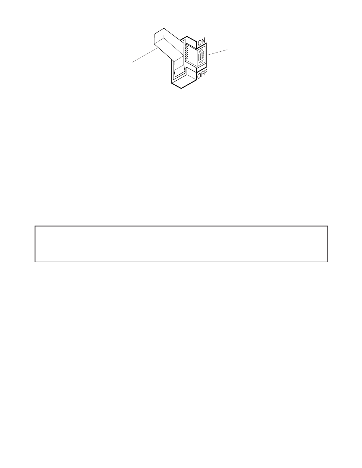
Figure 2 - Receiver's Master Switch
Master Switch
Toggle Switch
9. If not already there, slide the receiver's master switch, located beside the toggle
switch to its ON (up) position. The light may turn on at this time. NOTE: If you
are controlling a lamp, make sure it is connected to the switched outlet and that
the lamp is switched on.
10. Slide the receiver’s master switch to its OFF (down) position. Move the toggle
switch up and down. The light should remain off.
11. Slide the receiver’s master switch to its ON (up) position. Move the switch
lever up and down. The light should switch on and off.
12. Install the 9-volt battery. Remove the switch cover from the transmitter (save
the two screws). Snap the battery clips over the battery terminals and set the
battery into its compartment (see Figure 4).
13. To verify proper operation, hold the transmitter at the desired mounting location and switch it on. The light should turn on immediately. Turn the light off
and back on. If the light intermittently turns on or does not turn on at all, move
the transmitter slightly and try again. If it still does not operate properly, perform step 14, otherwise, skip the step.
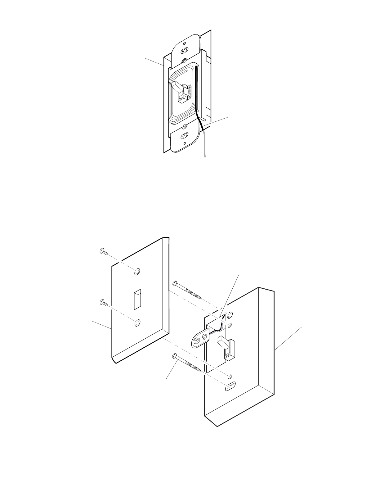
14. Unwind the antenna on the receiver from its track. Route the antenna through
the notch and fully extend it so that it hangs down inside the wall (see Figure 3).
This will increase the range of the receiver. Reposition the transmitter at the
desired location and make sure it operates the light. You may have to reposition
the receiving antenna or the transmitter until the light works properly.
15. Mount the transmitter at the desired location with the two wood screws that
are provided. NOTE: If your mounting surface requires a different type of mount-
ing hardware, please purchase the necessary hardware.
IMPORTANT: Wait at least 1 second after you switch the transmitter
on or off before you switch it again to allow the transmission to be
completed each time.
-4-
595-4918-05
16. Mount the switch plate supplied with the transmitter over the transmitter using
the screws that were supplied.
17. Mount the switch plate (not supplied) over the receiver with the screws you
removed earlier. This completes the installation.
Battery
Compartment
Wood Screw (2)
Transmitter
Switch
Plate
Figure 3 - Receiver's Antenna
Junction Box
Antenna
Figure 4 - Receiver Installation

-5-
595-4918-05
SYMPTOM
Light does not
come on.
Light does not
turn off.
Light comes
on randomly.
POSSIBLE CAUSE
1. Circuit breaker or fuse is turned off.
2. Switch on lamp is turned off.
3. Bulb is defective.
4. Receiver’s master switch is set to OFF.
5. Receiver wiring to house wiring loose.
6. Receiver antenna needs to be adjusted
1. Switching too fast.
2. Weak battery.
3. Transmitter out of range or metal object
blocking signal.
1. Short term power line failure.
2. Transmitter out of range.
Troubleshooting Guide
Specifications
Minimum Lighting Load ....................................25 Watts, incandescent only
Maximum Lighting Load ...................................Up to 500 Watts Maximum,
incandescent only
Rated Voltage ..................................................120 VAC, 60 Hz
Typical Range ..................................................Up to 100 feet (30 m)
Receiver Size ...................................................Fits in a standard wall box
Battery .............................................................. 9-volt alkaline
Technical Service
(Do Not Send Products)
If you experience a problem, follow this guide. You may also want to visit our Web
site at: www.desatech.com. If the problem persists, call* for assistance at 1-800-
858-8501, 7:30 AM to 4:30 PM CST (M-F). You may also write* to:
DESA Specialty Products™
P.O. Box 90004, Bowling Green, KY 42102-9004
ATTN: Technical Service Specialty Products
* If contacting Technical Service, please have the following information available:
Model Number, Date of Purchase, and Place of Purchase.
No Service Parts Available for this Product

-6-
595-4918-05
FIVE YEAR LIMITED WARRANTY
This is a “Limited Warranty” which gives you specific legal rights. You may also have
other rights which vary from state to state or province to province.
For a period of five years from the date of purchase, any malfunction caused by factory defective parts or workmanship will be corrected at no charge to you. Light bulbs
and Batteries not covered. To obtain a refund or a replacement, return the product to
the place of purchase.
Not Covered - Repair service, adjustment and calibration due to misuse, abuse or
negligence, light bulbs and other expendable items are not covered by this warranty.
Unauthorized service or modification of the product or of any furnished component will
void this warranty in its entirety. This warranty does not include reimbursement for
inconvenience, installation, setup time, loss of use, or unauthorized service.
This warranty covers only DESA Specialty Products™ assembled products and is not
extended to other equipment and components that a customer uses in conjunction
with our products.
THIS WARRANTY IS EXPRESSLY IN LIEU OF ALL OTHER WARRANTIES, EXPRESS
OR IMPLIED, INCLUDING ANY WARRANTY, REPRESENTATION OR CONDITION
OF MERCHANT ABILITY OR THAT THE PRODUCTS ARE FIT FOR ANY PARTICULAR PURPOSE OR USE, AND SPECIFICALLY IN LIEU OF ALL SPECIAL, INDIRECT,
INCIDENTAL, OR CONSEQUENTIAL DAMAGES.
REPAIR OR REPLACEMENT SHALL BE THE SOLE REMEDY OF THE CUSTOMER
AND THERE SHALL BE NO LIABILITY ON THE PART OF DESA SPECIALTY PRODUCTS™ FOR ANY SPECIAL, INDIRECT, INCIDENTAL, OR CONSEQUENTIAL DAMAGES, INCLUDING BUT NOT LIMITED TO ANY LOSS OF BUSINESS OR PROFITS,
WHETHER OR NOT FORESEEABLE. Some states or provinces do not allow the
exclusion or limitation of incidental or consequential damages, so the above limitation
or exclusion may not apply to you. Retain receipt for warranty claims.
Regulatory Information
The user is cautioned that changes or modifications not expressly approved by the
party responsible for regulatory compliance could void the user's authority to operate
the equipment.
This device complies with RSS-210 of Industry Canada. Operation is subject to the
following two conditions: (1) this device may not cause interference, and (2) this device must accept any interference, including interference that may cause undesired
operation of the device.
DESA Specialty Products™ reserves the right to discontinue products and to change
specifications at any time without incurring any obligation to incorporate new
features in products previously sold.
 Loading...