

Heath Zenith SL-5514 User Manual
Twin Halogen Motion
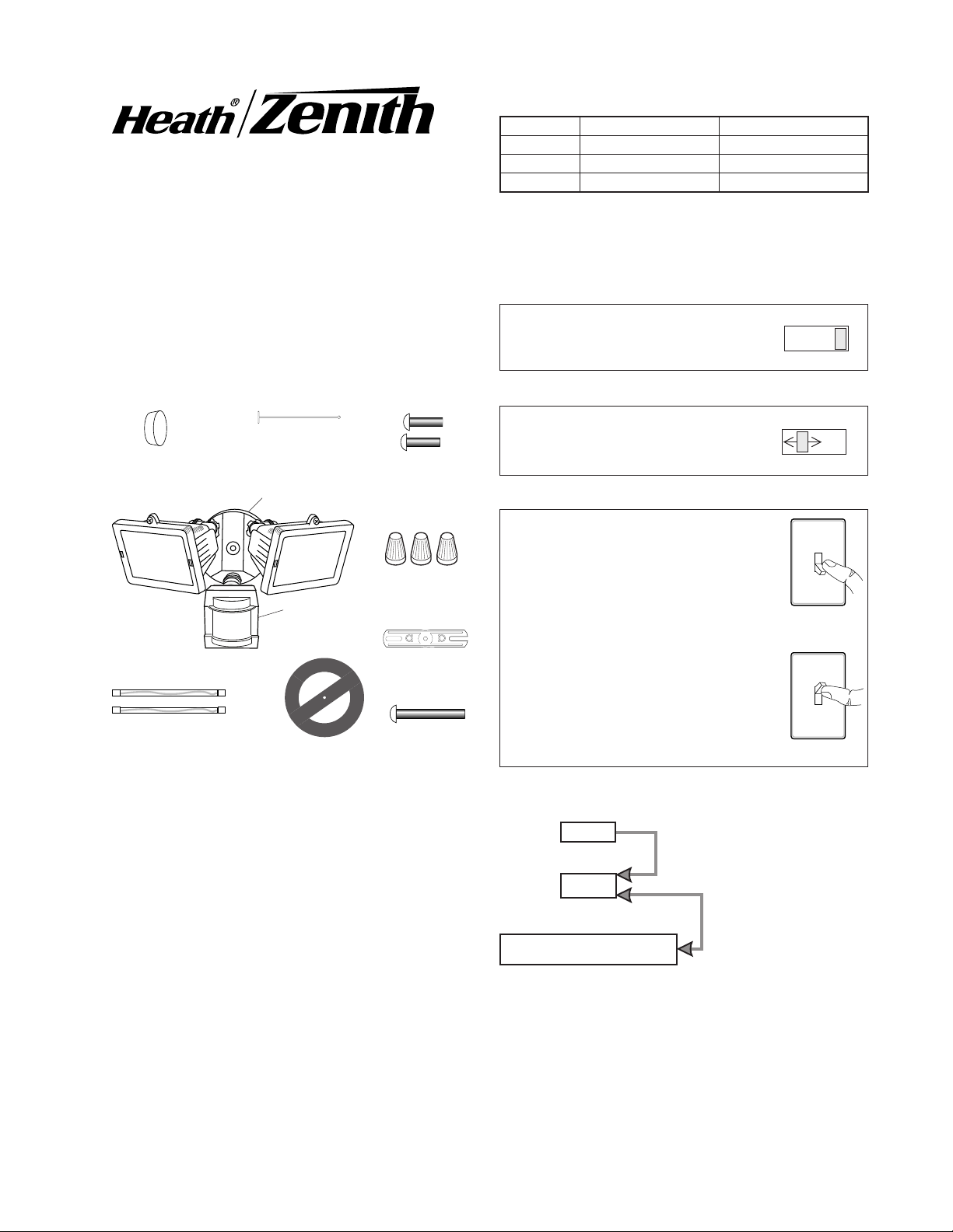
MANUAL MODE
AUTO
TEST
Sensing Light Control
OPERATION
Mode: On-Time Works: Day Night
Test
Auto
Manual
5 Seconds x x
1, 5, or 10 Min x
Until Dawn* x
* resets to Auto Mode at dawn.
Model SL-5514
Features
• Turns on lighting when motion is detected.
• Automatically turns lighting off.
• Photocell keeps the lighting off during daylight
hours.
This package includes:
Plastic Hanger
Rubber Plug
Cover Plate
Sensor
Light Control
2 Halogen Bulbs
Gasket
6 Mounting
Screws (3 sizes)
3 Wire
Connectors
Mounting Strap
Mounting Bolt
Note: When first turned on wait about 1 1/2 minutes for
the circuitry to calibrate.
TEST
Put the ON-TIME switch on the bottom
of the sensor in the TEST position.
AUTO
Put the ON-TIME switch in the 1, 5,
or 10 minute position.
MANUAL MODE
Manual mode only works at night
because daylight returns the sensor
to AUTO.
Flip the light switch off for one second
then back on to toggle between AUTO
and MANUAL MODE.
Manual mode works only with the
ON-TIME switch in the 1, 5, or 10
position.
ON-TIME
10 5 1 TEST
ON-TIME
10 5 1 TEST
1 Second
OFF then...
... back on.
• The light control requires 120-volts AC.
• If you want to use Manual Mode, the control must
be wired through a switch.
• Some codes require installation by a qualified
electrician.
• This product is intended for use with the enclosed
gasket and with a junction box marked for use in
wet locations.
© 2007 HeathCo LLC 595-5730-05
Requirements
Mode Switching Summary
Move ON-TIME Switch to
1, 5, or 10 minutes
Flip light switch off
for one second then
back on*
* If you get confused while switching modes, turn the
power off for one minute, then back on. After the calibration time the control will be in the AUTO mode.
INSTALLATION
For easy installation, select an existing light operated
by a wall switch for replacement.
For best performance, mount the fixture about 8 ft.
(2.4 m) above the ground.
CAUTION: To Avoid Fire Or Burn Hazards:
• Allow fixture to cool before touching. The bulb and
the fixture operate at high temperatures.
• Keep fixture at least 1" (2.5 cm) from combustible materials. Do not aim at objects closer than 3 ft. (1 m).
• Use only T3, 150W (max.) tungsten halogen 120
VAC lamps.
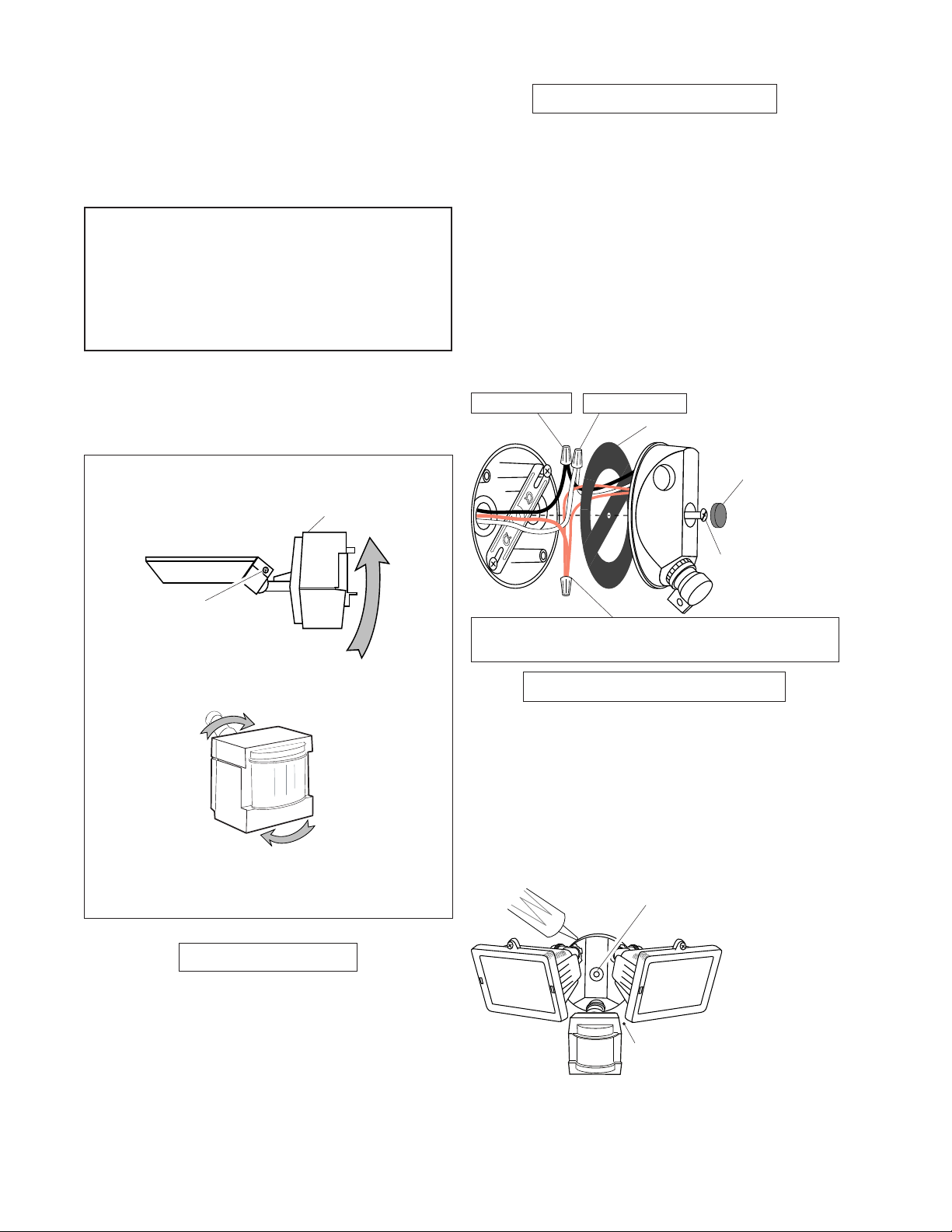
For under eave installation, the sensor head must
be rotated as shown in the next two steps for proper
operation and to avoid the risk of electrical shock.
For eave mount only:
❒ Rotate the sensor head towards the clamp screw
joint.
Control Switch
Wire the Light ControL
❒ Turn power off at the fuse or circuit breaker.
❒ Remove the existing light fixture.
❒ Install mounting strap to junction box using screws
appropriate for your junction box.
❒ The plastic hanger can be used to hold the fixture
while wiring. The small end of the plastic hanger
can be threaded through the hole in the center of
the cover plate. The small end then goes into one
of the slots on the mounting strap.
❒ Thread all fixture wires through the large holes in
the gasket as shown.
❒ Connect the junction box wires to the light fixture
wires as shown. Twist together and secure with wire
connectors.
Black to Black
White to White
Gasket
Rubber
Plug
Joint Clamp
❒ Then rotate the sensor head clockwise 180° so the
controls face down.
If the sensor pops out of the ball joint, loosen the
clamp screw and push the sensor back into the ball
joint. Tighten the clamp screw when done.
BuLB instaLLation
NOTE: When re-lamping, turn power off and let the
fixture cool.
❒ Open glass covers. To remove the old bulb push the
bulb towards the right (with fixture as shown) until
the left side of the bulb is clear of the left socket.
❒ To install a bulb, push the bulb into the right socket
so the bulb fits completely into the left socket.
❒ Check that the bulb is seated properly.
❒ Close the glass covers.
Mounting Bolt
Connect any fixture ground wire(s) and the cover plate
ground screw to the junction box ground wire.
Mount the Light ControL
❒ Place the mounting bolt through the front of the
junction box cover.
❒ Make sure the wire connectors and wires are inside
the junction box. Align the mounting screw with the
center hole in the mounting strap. Secure the fixture
to the mounting strap.
❒ Push the rubber plug firmly into place.
❒ If not installed on a weatherproof box, caulk the
wall plate and mounting surface with silicone.
Push the Rubber Plug over
the mounting screw.
Keep lamps at least 1" (2.5 cm)
from the sensor.
❒ Adjust the lamp holders by loosening the lock nuts
but do not rotate the lamp holders more than 180°
from the factory setting.
2
595-5730-05

TEST AND ADJUSTMENT
❒ Turn on the circuit breaker and light switch.
NOTE: Sensor has about 1 1/2 minutes warm up period
before it will detect motion. When first turned
on, wait about 1 1/2 minutes.
❒ Turn the SENSITIVITY (SENS) control to the mid
position and the ON-TIME control to the TEST
position.
ON-TIME
10 5 1 TEST
Bottom of Sensor
SENS
MIN MAX
❒ Loosen the clamp screw in the
sensor ball joint and gently
rotate the sensor.
❒ Walk through the coverage
area noting where you are
when the lights turn on. Move
the sensor head up, down, or
sideways to change the coverage area. Keep the sensor at
least 1" (2.4 cm) away from
the lamps.
❒ Adjust the SENSITIVITY as
needed. Too much sensitivity
may increase false triggering
❒ Secure the sensor head’s
aim by tightening the clamp
screw. Do not overtighten the
screw.
❒ Set the amount of TIME you
want the lights to stay on after motion is detected
(1, 5, or 10 minutes).
Aim Sensor
Down for Short
Coverage
Aim Sensor
Higher for Long
Coverage
Clamp
Screw
Ball
Joint
Avoid aiming the sensor at:
• Objects that change temperature rapidly, such as
heating vents and air conditioners. These heat
sources could cause false triggering.
• Areas where pets or traffic may trigger the control.
• Nearby large, light-colored objects reflecting light
may trigger the shut-off feature. Do not point other
lights at the sensor.
110°
8 ft.
(2.4 m)
60 ft.
(18.3 m)
Maximum Range Maximum
Coverage Angle
The detector is less sensitive to motion directly towards
it and more sensitive to across motion.
SPECIFICATIONS
Range . . . . . . . . . . . . . Up to 60 ft. (18.3 m) [varies with
surrounding temperature].
Sensing Angle . . . . . . . Up to 110°
Electrical Load . . . . . . . 300 watt Incandescent [150
Max each lamp holder].
Power Requirements . . 120 VAC, 60 Hz
Operating Modes . . . . . TEST, AUTO and MANUAL
MODE
Time Delay . . . . . . . . . 1, 5, 10 minutes
Replacement lamp . . . . T3 150W halogen maximum
120 VAC
HeathCo LLC reserves the right to discontinue prod-
ucts and to change specifications at any time without
incurring any obligation to incorporate new features in
products previously sold.
MotionMotion
Sensor
Least Sensitive Most Sensitive
595-5730-05
3

TROUBLESHOOTING GUIDE
SYMPTOM
Lights will not
come on.
Lights come on
in daylight.
Lights come on
for no apparent
reason.
POSSIBLE CAUSE
1. Light switch is turned off.
2. Light is loose or burned out.
3. Fuse is blown or circuit breaker is
turned off.
4. Daylight turn-off is in effect (recheck
after dark).
5. Incorrect circuit wiring, if this is a
new installation.
6. Re-aim the sensor to cover desired
area.
1. Light control may be installed in a
relatively dark location.
2. Light control is in Test. (Set control
switch to an ON-TIME position.)
1. Light control may be sensing small
animals or automobile traffic (re-aim
sensor).
2. Sensitivity is set too high. (Reduce
sensitivity.)
SYMPTOM
Lights stay on
continuously.
Lights flash
on and off.
POSSIBLE CAUSE
1. A lamp is positioned too close to the
sensor or pointed at nearby objects
that cause heat to trigger the sensor.
(Reposition the lamp away from the
sensor or nearby objects.)
2. Sensor is pointed toward a heat
source like an air vent, dryer vent,
or brightly-painted heat-reflective
surface. (Reposition sensor.)
3. Light control is in Manual Mode.
(Switch to Auto.)
1. Heat or light from the lamps may be
turning the light control on and off.
(Reposition the lamps away from the
sensor.)
2. Heat being reflected from other objects
may be affecting the sensor. (Reposi-
tion sensor.)
3. Light control is in the Test mode and
warming up. (Flashing is normal under
TECHNICAL SERVICE
Please call 1-800-858-8501 (English speaking only) for assistance before returning
product to store.
If you experience a problem, follow this guide. You may also want to visit our Web site at: www.hzsupport.com.
If the problem persists, call* for assistance at 1-800-858-8501 (English speaking only), 7:30 AM to 4:30 PM CST
(M-F). You may also write* to:
HeathCo LLC
P.O. Box 90004, Bowling Green, KY 42102-9004
ATTN: Technical Service
* If contacting Technical Service, please have the following information available: Model Number, Date of Purchase, and Place of Purchase.
No Service Parts Available for this Product
This is a “Limited Warranty” which gives you specific legal rights. You may also have other rights which vary from state to state or
ONE YEAR LIMITED WARRANTY
province to province.
For a period of one year from the date of purchase, any malfunction caused by factory defective parts or workmanship will be corrected
at no charge to you.
Not Covered - Repair service, adjustment and calibration due to misuse, abuse or negligence, light bulbs, batteries, and other expendable items are not covered by this warranty. Unauthorized service or modification of the product or of any furnished component will
void this warranty in its entirety. This warranty does not include reimbursement for inconvenience, installation, setup time, loss of use,
unauthorized service, or return shipping charges.
This warranty covers only HeathCo LLC assembled products and is not extended to other equipment and components that a customer
uses in conjunction with our products.
THIS WARRANTY IS EXPRESSLY IN LIEU OF ALL OTHER WARRANTIES, EXPRESS OR IMPLIED, INCLUDING ANY WARRANTY,
REPRESENTATION OR CONDITION OF MERCHANT ABILITY OR THAT THE PRODUCTS ARE FIT FOR ANY PARTICULAR PURPOSE OR USE, AND SPECIFICALLY IN LIEU OF ALL SPECIAL, INDIRECT, INCIDENTAL, OR CONSEQUENTIAL DAMAGES.
REPAIR OR REPLACEMENT SHALL BE THE SOLE REMEDY OF THE CUSTOMER AND THERE SHALL BE NO LIABILITY ON THE
PART OF HEATHCO LLC FOR ANY SPECIAL, INDIRECT, INCIDENTAL, OR CONSEQUENTIAL DAMAGES, INCLUDING BUT NOT
LIMITED TO ANY LOSS OF BUSINESS OR PROFITS, WHETHER OR NOT FORESEEABLE. Some states or provinces do not allow
the exclusion or limitation of incidental or consequential damages, so the above limitation or exclusion may not apply to you. Please
keep your dated sales receipt, it is required for all warranty requests.
4
595-5730-05
 Loading...