

Page 1
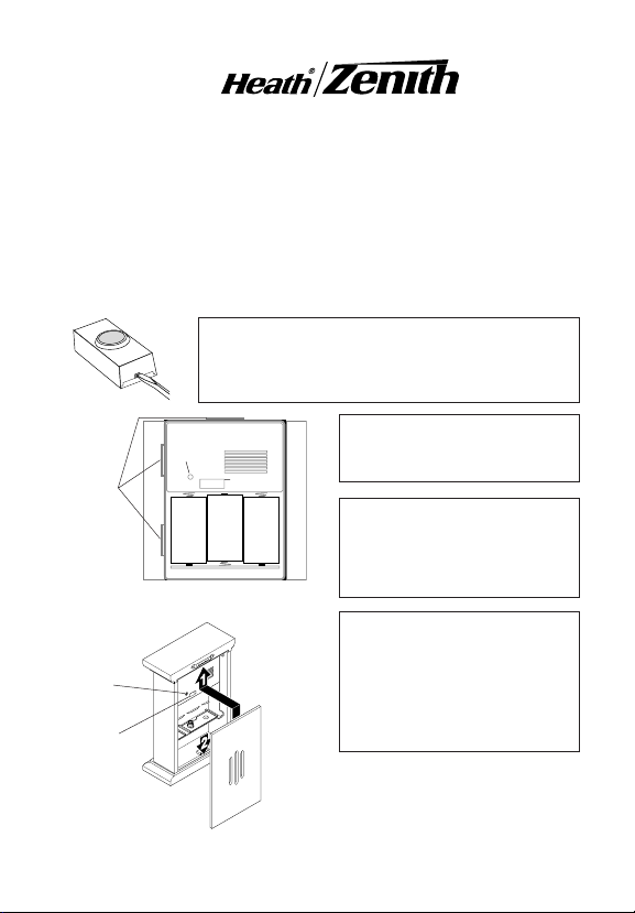
Decorative Wireless Chime
6180 Series and 6280 Series
This package includes (Style of push button and chime may vary from illustrations):
• Wireless chime
• Wireless push button w/battery
• Hardware pack
You'll need to buy 3 "D" alkaline batteries for the chime (Clock chime
models require additional "AA" battery). In typical use, alkaline batteries
will last up to three years.
1.Install alkaline type A23 12 volt push button bat-
tery. Remove back of case by pushing in tab on
bottom with a small screwdriver. Make sure battery
is oriented properly (see page 4).
2.Install 3 alkaline "D" batter-
ies. Make sure batteries are
oriented properly.
The base may be mounted in a
vertical or horizontal position.
The correct mounting position
will depend upon the specific
cover (model).
3. Test range. Temporarily posi-
Cover
Mounting
Tabs
Chime
Volume
Jumpers
+
-
Battery
+
Battery
-
-
Battery
+
Case Style "A" (Shown
In Vertical Position)
tion chime and push button
where you want them mounted.
Chime
Volume
Jumpers
8
7
6
5
4
3
2
1
Press push button to verify
chime and push button work
properly. If chime does not
sound, see Troubleshooting.
Case Style "B"
© 2003 DESA Specialty Products™ 595-5506-09
Page 2
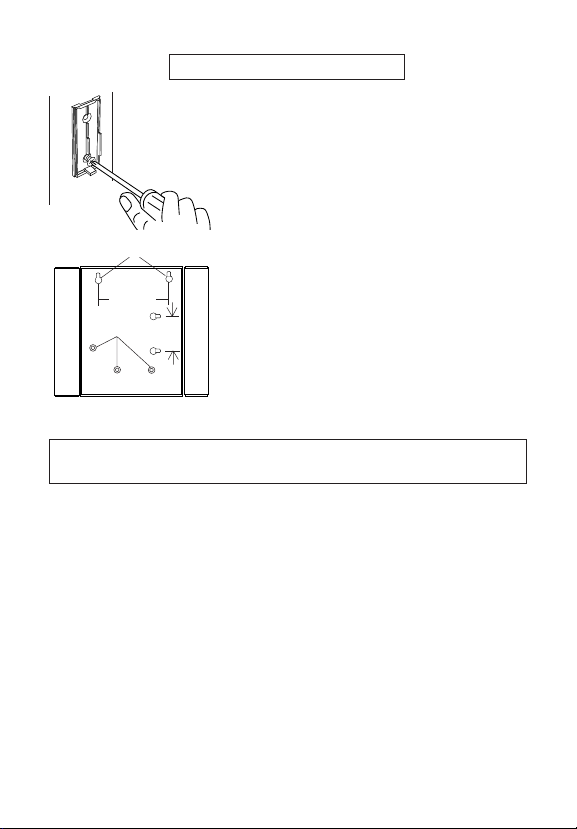
4. Mount push button and chime.
Use either screws or double sided tape to mount
push button.
To mount with screws, remove back of case by
pushing in tab on bottom with a small screwdriver.
Attach back of case to door jamb or wall. Snap
front of push button on.
When attaching push button using double sided
tape, make sure the surface of the door jamb or
Keyholes
wall is clean.
Case Style "A": Chime can be mounted by us-
ing 3 holes in the back of case, or by using 2
211⁄16 "
Holes
screws with keyholes.
2
Case Style "B": Chime can be mounted by us-
1
/
2
ing 1 large screw (provided) with saw-tooth
"
hanger. Securely fasten saw-tooth hanger to rear
of case using screws (or nails) provided (see illustration on page 1). It can also be placed on a
Case Style "A"
flat surface.
Back
5.Slide chime cover onto top of chime. Use technique for the style case
you have. Mounting groove in cover will align with mounting tab(s) on base.
-2-
595-5506-09
Page 3
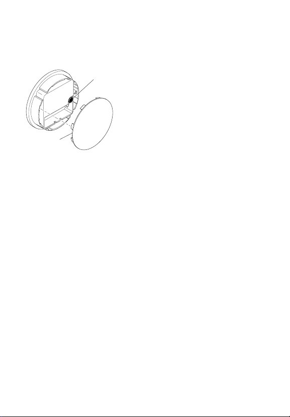
Clock Chimes
Note: This feature is only available on specific models.
Battery
Cover
chime back. Grasp cutouts on back of chime with fingers. Gently push back up
and pull lower part of back out to remove. Install 3 alkaline "D" batteries according to polarity marks inside battery chamber. Replace back of chime by
following the above instructions in reverse (see illustration on page 1).
Battery Installation and Setting Time
Time Setting
1. Install battery into clock. Firmly grasp brass
ring and carefully pull forward to remove clock
Dial
assembly from front of chime. Gently pull off battery cover located on back of clock assembly. Install "AA" battery according to polarity marks inside battery chamber. Replace battery cover.
2. Set time. With battery cover removed, turn
time setting dial on back of clock assembly until
time is correct. Replace battery cover. Replace
clock assembly into chime face by pressing assembly gently into hole on chime face.
3. Install batteries into chime. Remove clock
Code and Tune Settings
Note: Most installations will not require you to change any jumpers on
your chime and push button.
The push button and chime communicate by using a code that can be changed
by removing and/or adding jumpers on both the push button and chime. The
code is factory set; however, there are 128 selectable codes that allow you
to expand your system and prevent outside interference. Other wireless products may cause interference and the system may not function properly. Follow the instructions below for setting a new code.
1. Open the cases and locate the jumpers on both the push button and chime
(See illustration on page 4).
2. The push button and chime both have eight different jumper locations.
The jumper positions 1 through 7 are used for setting the code.
3. To change the code, add and/or remove jumpers as needed. It is recommended to only change one jumper at a time and then check to see if
system is functioning properly. Note: Jumpers in positions 1 through 7
must be exactly the same for both the push button and chime for this
system to function.
Code Settings
595-5506-09
-3-
Page 4
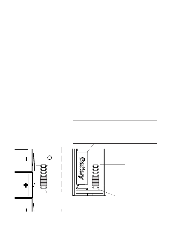
BBattery
C
h
i
m
e
V
o
l
u
m
e
Your Heath
®
/Zenith wireless chime has different selectable tunes: Ding (one
Tune Settings
note), Ding-Dong (two note), or Westminster (eight note) (Available on selected Heath®/Zenith chimes). The factory setting is for the Ding-Dong tune
(or Westminster, when available). This tune can be changed by following the
instructions below.
• Ding (one note tune)
Push Button: Add a jumper to location 8.
• Ding-Dong (two note tune)
Push Button: Remove jumper from location 8.
Chime: Remove jumper from location 8.
• Westminster (Eight note tune) (Available on selected Heath®/Zenith chimes)
Push Button: Remove jumper from location 8.
Chime: Add a jumper to location 8.
Note: All models have both front and back door tune capabilities. You may
purchase any Heath
®
/Zenith wireless push button for a second entrance. We
recommend the back door use the Ding tune and the front door use the
Ding-Dong tune (or Westminster tune, available on selected Heath®/Zenith
chimes). Models that include two push buttons will come factory set for front
and back doors. Decals on the rear of the push button will indicate its setting.
Push Button Battery Replacement
Install an alkaline type A23 12 Volt battery. See diagram inside push button for
Inside Chime
correct battery orientation.
12345678
Tune Setting
(Not used on
all models)
12345678
* Code Settings 1-7
Must Match Both
Push Button and
Chime
Inside Push
Button
Tune
Setting
Note: Some models might require the use of
tweezers to remove and replace the jumpers.
-4-
595-5506-09
Page 5

Troubleshooting
Chime does not sound:
• Make sure push button and chime codes are the same (See pages 3 and 4).
• Check orientation of push button battery (See page 4).
• Check charge of push button and chime batteries, replace if necessary.
Batteries seem OK, but the chime does not work when installed:
• Do not mount chime or push button on metal or near metal studs. This
reduces the transmitter range. Use 1/4" to 1/2" (6 to 13 mm) wood shims
to move chime or push button off metal surface.
• Concrete floors may reduce range. Move chime away from floor.
•Try locating chime closer to push button.
The range of the wireless chime can vary with location, temperature and
battery condition.
Technical Service
If you experience a problem, follow this guide. You may also want to visit our Web
site at: www.desatech.com. If the problem persists, call* for assistance at 1-
800-858-8501, 7:30 AM to 4:30 PM CST (M-F). You may also write* to:
DESA Specialty Products™
P.O. Box 90004, Bowling Green, KY 42102-9004
ATTN: Technical Service Specialty Products
* If contacting Technical Service, please have the following information available: Model Number, Date of Purchase, and Place of Purchase.
No Service Parts Available for this Product
(Do Not Send Products)
Regulatory Information
This device (SL-6180-RX-A, WB-94A-TX, or WB-97-TX) complies with Part
15 of the FCC Rules and RSS-210 of Industry Canada. Operation is subject
to the following two conditions: (1) this device may not cause harmful interference, and (2) this device must accept any interference received, including
interference that may cause undesired operation.
The term “IC:” before the radio certification number only signifies that Industry Canada
technical specifications were met.
The user is cautioned that changes or modifications not expressly approved
by the party responsible for regulatory compliance could void the user’s authority to operate the equipment.
595-5506-09
-5-
Page 6
This is a “Limited Warranty” which gives you specific legal rights. You may also
LIMITED WARRANTY
have other rights which vary from state to state or province to province.
For a specified period depending upon model (see chart below) from the date
of purchase, any malfunction caused by factory defective parts or workmanship
will be corrected at no charge to you. Batteries are not covered. To obtain a
refund or a replacement, return the product to the place of purchase.
Not Covered - Repair service, adjustment and calibration due to misuse, abuse
or negligence, light bulbs and other expendable items are not covered by this
warranty. Unauthorized service or modification of the product or of any furnished
component will void this warranty in its entirety. This warranty does not include
reimbursement for inconvenience, installation, setup time, loss of use, or
unauthorized service.
This warranty covers only DESA Specialty Products™ assembled products and
is not extended to other equipment and components that a customer uses in
conjunction with our products.
THIS WARRANTY IS EXPRESSLY IN LIEU OF ALL OTHER WARRANTIES,
EXPRESS OR IMPLIED, INCLUDING ANY WARRANTY, REPRESENTATION
OR CONDITION OF MERCHANT ABILITY OR THAT THE PRODUCTS ARE FIT
FOR ANY PARTICULAR PURPOSE OR USE, AND SPECIFICALLY IN LIEU OF
ALL SPECIAL, INDIRECT, INCIDENTAL, OR CONSEQUENTIAL DAMAGES.
REPAIR OR REPLACEMENT SHALL BE THE SOLE REMEDY OF THE CUSTOMER AND THERE SHALL BE NO LIABILITY ON THE PART OF DESA SPECIALTY
PRODUCTS™ FOR ANY SPECIAL, INDIRECT, INCIDENTAL, OR CONSEQUENTIAL DAMAGES, INCLUDING BUT NOT LIMITED TO ANY LOSS OF BUSINESS OR
PROFITS, WHETHER OR NOT FORESEEABLE. Some states or provinces do not
allow the exclusion or limitation of incidental or consequential damages, so the above
limitation or exclusion may not apply to you. Retain receipt for warranty claims.
Model Warranty Period
6280, 6281, 6282 3 Years
6180 Series, 6283, 6284, 6285 5 Years
DESA Specialty Products™ reserves the right to discontinue and to change
specifications at any time without notice without incurring any obligation to
incorporate new features in previously sold products.
-6-
595-5506-09
Page 7

Campanilla Decorativa Inalámbrica
Serie 6180 y Serie 6280
Este paquete tiene (El estilo del pulsador y de la campana puede variar de la
ilustración):
• Campana Inalámbrica
• Pulsador inalámbrico con batería
• Paquete de ferretería
Usted deberá comprar 3 pilas alcalinas “D” para el timbre. (Los modelos
de campanilla de reloj requieren pilas adicionales “AA”). Con un uso normal,
las pilas alcalinas durarán hasta tres años.
1.Instalar pila alcalina de botón tipo A23 de 12
voltios. Extraer la parte posterior de la caja
presionando la aleta en el botón con un destornillador
pequeño. Asegurarse que la pila esté orientada
correctamente (ver la página 11).
2.Coloque las 3 pilas alkalinas
“D”. Asegúrese de que estén
correcta-mente colocadas.
La base puede estar montada en
una posición vertical u horizontal. La posición correcta de
montaje dependerá de la
cubierta específica (modelo).
3.Pruebe el alcance. Ponga
provisionalmente la campana y
el pulsador en la posición donde
los quiera instalar. Presione el
pulsador para verificar que la
campanay el pulsador
funcionen apropiadamente. Si
la campana no suena, vea
Análisis de Averías.
Aletas de
montaje
de la
cubierta
Control del
Volumen de
la Campana
Puentes
Control del Volumen
de la Campana
Puentes
+
-
Battery
+
Battery
-
-
Battery
+
Caja Estilo “A” (Mostradas
en posición vertical)
8
7
6
5
4
3
2
1
© 2003 DESA Specialty Products™ 595-5506-09 S
-7-
595-5506-09
Caja Estilo “B”
Page 8

4. Instale el pulsador y el timbre.
Use ya sean tornillos o cinta adhesiva por ambas
caras para instalar el pulsador.
Para montar con tornillos, quite la parte de atrás de
la caja empujando hacia adentro la lengüeta de abajo
con un destornillador pequeño y girando la cuchilla.
Coloque la parte de atrás de la caja contra la
jamba o la pared. Encaje a presión la parte frontal del pulsador.
Cuando fije el pulsador usando cinta adhesiva por
Agujeros
68 mm
Agujeros
Caja estilo “A”
mm
Atrás
ambas caras, asegúrese que la superficie de la
pared o la del batiente de la puerta estén limpias.
Caja Estilo “A”: La campana puede ser montada
usando los 3 huecos en la parte de atrás de la
caja o dos tornillos en los huecos.
64
Caja Estilo “B”: La campana puede ser montada
usando 1 tornillo largo (provisto) con colgador con
diente de sierra. Asegure bien este colgador en la
parte de atrás de la caja usando los tornillos (o clavos)
provistos (ver la ilustración en la página 7). Se puede
colocar también sobre una superficie plana.
5.Deslice la tapa de la campana por sobre la parte superior de la campana.
Use la técnica apropiada para el estilo de caja que tenga. La ranura de
montaje en la cubierta se alinea con la aleta(s) de montaje en la base.
-8-
595-5506-09
Page 9

Campanillas De Reloj
Nota: Esta característica está disponible solamente para modelos
cubierta de la pila
Volver a colocar el conjunto del reloj dentro de la superficie de la campanilla
presionando suavemente dentro del orificio de la superficie de la campanilla.
3. Instalar las pilas dentro de la campanilla. Quite la parte de atrás de la
campana del reloj. Agarre con los dedos las partes removibles de la parte de
atrás de la campana. Empuje suavemente hacia arriba y hale la parte inferior trasera para quitar. Instalar 3 pilas alcalinas “D” de acuerdo con las marcas
de polaridad dentro de la cámara de la pila. Ponga de nuevo la parte de
atrás de la campana siguiendo en reverso los pasos indicados arriba (ver la
ilustración en la página 7).
Instalación de la pila y graduación del tiempo
específicos.
Cuadrante de
graduación de
hora
Placa de
1. Instalar la pila en el reloj. Sujetar
firmemente el anillo de bronce y tirar
cuidadosamente hacia adelante para
extraer el conjunto del reloj de la parte
delantera de la campanilla. Hale y quite
suavemente la tapa de la pila ubicada en la
parte de atrás del conjunto del reloj. Instalar
la pila “AA” de acuerdo con las marcas de
polaridad dentro de la cámara de la pila.
Volver a colocar la cubierta de la pila.
2. Graduar la hora. Una vez quitada la
tapa de la pila, gire el dial fijador de la hora,
en la parte de atrás del reloj, hasta la hora
correcta. Ponga de nuevo la tapa de la pila.
595-5506-09
-9-
Page 10

Programaciones del código y del tono
Programaciones del código
Nota: En la mayoría de instalaciones no será necesario que cambie
ningún puente en su campana o en su pulsador.
El pulsador y la campana se comunican usando un código que puede ser
cambiado quitando y/o añadiendo puentes en el pulsador y la campana. El
código ha sido programado en fábrica; sin embargo, hay 128 códigos elegibles
que le permiten expandir su sistema y evitar interferencia externa. Otros
productos inalámbricos pueden causar interferencia y puede ser que el
sistema no funcione como es debido. Para programar un nuevo código siga
las siguientes indicaciones:
1. Abra las cajas y localice los puentes tanto en el pulsador como en la
campana (vea la ilustración en la página 11).
2. Tanto el pulsador como la campana tienen ocho posiciones diferentes de
los puentes. Las posiciones de puente del 1 al 7 se usan para programar
el código.
3. Para cambiar el código añade y/o quite los puentes, como sea necesario.
Se recomienda cambiar tan sólo un puente por vez y luego comprobar si
el sistema funciona correctamente. Nota: Para que funcione este sistema,
las posiciones de la 1 a la 7 de los puentes deben ser iguales tanto en el
pulsador como en la campana.
Su campana inalámbrica Heath
seleccionarse: Tilín (una nota), Tilín-Talán (dos notas), o Westminster (ocho
notas) (Disponible en los timbres Heath®/Zenith seleccionados). La calibración
de fábrica es el tono Tilín-talán (o el tono Westminster cuando está disponible).
Este tono puede ser cambiado siguiendo las instrucciones que siguen.
Programación del tono
®
/Zenith tiene tonos diferentes que pueden
-10-
595-5506-09
Page 11

BBattery
C
h
i
m
e
V
o
l
u
m
e
• Tilín (tono de una nota)
Pulsador: aumente un puente al sitio 8.
• Tilín-talán (tono de dos notas)
Pulsador: Quite el puente del sitio 8.
Campana: Quite el puente del sitio 8.
• Westminster (tono de ocho notas) (Disponible en los timbres Heath
Zenith seleccionados)
Pulsador: Quite el puente del sitio 8.
Campana: Aumente un puente al sitio 8.
Nota: Todas las campanas tienen capacidad de tonos para las puertas frontal y posterior. Usted puede comprar cualquier pulsador Heath®/Zenith
inalámbrico para una segunda puerta de entrada. Recomendamos que la
puerta posterior use el tono Tilín y la puerta frontal el tono Tilín-Talán ( o el
tono Westminster, disponible en los timbres Heath®/Zenith seleccionados).
Los modelos que incluyen dos pulsadores vendrán con la calibración de
fábrica para las puertas frontal y posterior. Las calcomanías en la parte posterior del pulsador le indicarán la calibración.
Reemplazo de la Batería del Pulsador
Cámbiela con una pila alcalina tipo A23 de
12 V. Vea el diagrama dentro del pulsador para
la orientación correcta de la pila.
Campana Interna
®
/
595-5506-09
12345678
Programación
del tono (No se
usa en todos
los modelos)
12345678
* Las Calibraciones de
Código del 1-7 Deben
Coincidir Tanto en el Pulsador
Como en el Timbre.
Programación
Dentro del
del tono
Pulsador
Nota: Algunos modelos podrían
requerir el uso de pinzas especiales
para retirar y colocar los puentes.
-11-
Page 12

Análisis de Averías
La campana no suena:
• Asegúrese que los códigos del pulsador y de la campana sean los mismos
(Vea las páginaciones 10 y 11).
•Verifique la posición de la batería del pulsador (Ver página 11).
• Revise la carga de las baterías del pulsador y de la campana, reemplácelas
si es necesario.
La pilas parecen estar buenas pero la campana no funciona una vez
instalada:
• No instale la campana o el pulsador sobre superficies metálicas o cerca
de montantes metálicos. Esto reduce el alcance del transmisor. Use cuñas
de madera de 6 a 13mm para aislar al pulsador de la superficie metálica.
• Los pisos de concreto pueden reducir el alcance. Mueva la campana fuera
del piso.
•Trate de ubicar a la campana lo más cerca del pulsador.
El alcance de la campana inalámbrica puede variar con: la ubicación,
temperatura y condiciones de la batería.
Servicio Técnico
Si tiene algún problema por favor siga esta guía. Lo sentimos, pero no podemos
contestar preguntas en español por teléfono. Usted puede también escribir* a:
DESA Specialty Products™
P.O. Box 90004, Bowling Green, KY 42102-9004
* Si se llama al Servicio Técnico, por favor tener lista la siguiente información:
Número de Modelo, Fecha de compra y Lugar de compra.
No hay piezas de servicio disponibles para este producto
(No enviar los productos)
Información Regulatoria
Este aparato (SL-6180-RX-A, WB-94A-TX, o WB-97-TX) cumple con la Parte
15 de las Reglas de la FCC (Comisión Federal de Comunicaciones) y con la
RSS-210 de las Industrias del Canadá. El funcionamiento está sujeto a las
dos siguientes condiciones: (1) este aparato no puede causar interferencias
dañinas, y (2) este aparato debe aceptar cualquier interferencia recibida,
incluyendo una interferencia que pueda causar un funcionamiento indeseable.
El término “IC:” delante del número de cerntificación del radio significa tan
solamente que se ha cumplido con las especificaciones técnicas de Industry
Canada.
Se advierte al usuario que cambios o modificaciones no aprobadas
expresamente por la parte responsable de cumplir con los reglamentos podría
invalidar la autoridad del usuario para el uso de este equipo.
-12-
595-5506-09
Page 13

Esta es una “Garantía Limitada” que le da a Ud. derechos legales específicos.
GARANTÍA LIMITADA
Usted puede también tener otros derechos que varían de estado a estado o
de provincia a provincia.
Por un período específico desde la fecha de compra y dependiendo del modelo
(vea el cuadro de abajo) cualquier funcionamiento defectuoso ocasionado
por partes o mano de obra defectuosas de fábrica será arreglado sin costo
para usted. Las pilas no están cubiertos banjo de esta garantia. Para
obtener el reembolso o reemplazo, devuelva el producto al lugar de compra.
No cubierto - Los servicios de reparación, regulación y calibración debidos
al mal uso, abuso o negligencia, las bombillas y otras partes fungibles no se
cubren con esta garantía. Los Servicios no autorizados o modificaciones del
producto o de cualquier componente que se provee invalidarán esta garantía
en su totalidad. Esta garantía no incluye reembolso por inconveniencia,
instalación, tiempo de montaje, pérdida por uso, o servicio no autorizado.
Esta garantía cubre solamente los productos ensamblados por DESA Specialty Products™ y no se extiende a otros equipos o componentes que el
consumidor usa junto con nuestros productos.
ESTA GARANTÍA ESTÁ EXPRESAMENTE EN LUGAR DE OTRAS
GARANTÍAS, EXPRESADAS O SOBREENTENDIDAS, INCLUYENDO
CUALQUIER GARANTÍA, REPRESENTACIÓN O CONDICIÓN DE
COMERCIABILIDAD O QUE LOS PRODUCTOS SE ADAPTEN PARA
CUALQUIER PROPÓSITO O USO EN PARTICULAR, Y ESPECIFICAMENTE
EN LUGAR DE TODOS LOS DAÑOS ESPECIALES, INDIRECTOS,
INCIDENTALES Y CONSECUENTES.
LA REPARACIÓN O EL REEMPLAZO DEBERÍA SER LA ÚNICA SOLUCIÓN
DEL CLIENTE Y NO HABRÁ RESPONSABILIDAD POR PARTE DE DESA
SPECIALTY PRODUCTS™ POR CUALQUIER DAÑO ESPECIAL, INDIRECTO,
INCIDENTAL O CONSECUENTE, INCLUIDOS PERO NO LIMITADOS A
CUALQUIER PÉRDIDA DE NEGOCIO O GANACIAS SEAN O NO PREVISIBLES.
Algunos estados o provincias no permiten la exclusión o limitación de daños
incidentales o consecuentes, de modo que la limitación o exclusión arriba indicada
puede que no se aplique a Ud. Guarde el recibo para reclamos de garantía.
Modelo Período de Garantía
6280, 6281, 6282 3 Años
6180 Series, 6283, 6284, 6285 5 Años
DESA Specialty Products™ se reserva el derecho de descontinuar y de
cambiar las especificaciones a cualquier momento, sin previo aviso, sin
incurrir en ninguna obligación de tener que incorporar nuevas características
en los productos vendidos anteriormente.
595-5506-09
-13-
Page 14

Carillon décoratif sans fil
Série 6180 et série 6280
Cet emballage contient (Le style de l’unité de bouton-poussoir et du carillon
peut varier par rapport à l’illustration):
• Carillon dans fil
• Unité de bouton-poussoir sans fil, avec pile
• un ensemble de ferrures
Vous aurez besoin de trois piles alcalines “D” (R20) pour le carillon
(Les modèles de carillon à horloge requièrent une pile « AA » en plus
des autres piles). En utilisation typique, les piles alcalines durent trois ans.
1.Installation de la pile alcaline 12 V de type A23
pour bouton-poussoir. Ôtez la partie arrière du
boîtier en enfonçant la patte du bas au moyen d’un
petit tournevis. Assurez-vous que la pile est orientée
correctement (voir p. 18).
Pattes de
montage
du
couvercle
(Montré en position verticale)
Commande
de volume du
carillon
Cavaliers
© 2003 DESA Specialty Products™ 595-5506-09 F
Commande de
volume du carillon
Cavaliers
+
-
Battery
Battery
-
+
Boîtier, style «A»
12345678
Boîtier, style «B»
-
Battery
+
2.Installez 3 piles alcalines “D”
(R20). Prenez soin d’orienter
les piles correctement.
La base se monte en position
verticale ou horizontale. La bonne
position de montage dépend du
couvercle (modèle) précis.
3.Plage d’essai. Positionnez
temporairement le carillon et
l’unité de bouton-poussoir à
l’endroit où vous voulez les
monter.Enfoncez le boutonpoussoir pour vous assurer
que celui-ci et le carillon
fonctionnent correctement. Si
le carillon ne retentit pas,
consultez la section
«Dépannage».
-14-
595-5506-09
Page 15

4. Montez l’unité de bouton-poussoir et le carillon.
Utilisez soit des vis, soit du ruban adhésif double
face pour monter l’unité de bouton-poussoir.
Pour faire l’installation avec les vis, enlevez le
dos du boîtier en poussant sur les agrafes de la
base avec un tournevis.
Fixez le dos du boîtier au chambranle ou au mur.
Enclenchez la partie avant de l’unité de boutonpoussoir en place.
Lorsque vous montez l’unité de bouton-poussoir
Trous de serrure
68 mm
mm
Trous
Boîtier, style «A», dos
en utilisant du ruban adhésif double face,
assurez-vous que la surface du montant de
porte ou du mur est propre.
Boîtier, style «A» : Il est possible d’installer le
carillon en utilisant les 3 trous du dos du boîtier
64
ou en utilisant deux vis avec les trous de serrure.
Boîtier, style «B» : Le carillon peut être installé au
moyen d’une grande vis (fournie) et d’un crochet
étrier denté. Fixez solidement le crochet étrier denté
à l’arrière du boîtier au moyen des vis (ou des clous)
fournies (voir l’illustration de la p. 14). On peut aussi
le mettre debout sur une surface plane.
5.Faire glisser le couvercle sur le dessus du carillon. Utiliser la technique
convenant au style de boîtier de votre carillon. La rainure de montage dans
le couvercle s’aligne avec la (les) patte(s) de montage de la base.
595-5506-09
-15-
Page 16

Carillons à horloge
Remarque : Caractéristique offerte sur certains modèles seulement.
Plaque-couvercle du
compartiment à pile
l'arrière de l'ensemble de l'horloge, en faisant tourner le cadran. Remettez
en place le couvercle du compartiment. Remettez en place l’unité de l’horloge à l’intérieur du carillon par le devant, en poussant sur l’unité délicatement
pour qu’elle entre dans l’ouverture du devant du carillon.
3. Installation des piles dans le carillon. Déposez la partie arrière du ca-
rillon à horloge. Avec vos doigts, saisissez le dos du carillon par les découpes. Poussez délicatement vers le haut, puis tirez la partie inférieure du dos
vers l'extérieur pour l'ôter. Introduisez trois (3) piles « D » alcalines selon les
marques de polarité prévues à l’intérieur du compartiment. Remettez en place
la partie arrière du carillon en suivant les étapes ci-dessus en sens inverse
(voir l’illustration en page 14).
Installation des piles et réglage de l’heure
Cadran de réglage
de l’heure
1. Installation de la pile dans l’unité de
l’horloge. Saisissez fermement l’anneau de
laiton, puis tirez-le délicatement vers l’avant
pour enlever l’unité de l’horloge par le devant du carillon. Détachez délicatement le
couvercle du compartiment à piles de l'arrière de l'ensemble de l'horloge. Introduisez
une pile « AA » selon les marques de polarité prévues à l’intérieur du compartiment.
Remettez en place la plaque-couvercle du
compartiment.
2. Réglage de l’heure. Le couvercle du compartiment à piles ayant été enlevé, réglez
l'heure au cadran de réglage de l'heure de
-16-
595-5506-09
Page 17

Réglages du code et de la mélodie
Remarque : Avec la plupart des installations, vous n’avez pas à changer aucun cavalier sur votre carillon ou votre unité de bouton-poussoir.
L’unité de bouton-poussoir et le carillon communiquent l’un avec l’autre en
utilisant un code, que l’on peut changer par ajout et/ou enlèvement de cavaliers au niveau de l’unité de bouton-poussoir et du carillon. Le code est réglé
en usine; 128 codes peuvent être sélectionnés de manière à vous permettre
d’étendre votre système et de prévenir les parasites extérieurs. La présence
d'autres appareils sans fil peut occasionner des parasites pouvant nuire au
bon fonctionnement du système. Pour régler le nouveau code, suivre les
directives ci-dessous.
1. Ouvrez les boîtiers, et repérez les cavaliers de l’unité du bouton-poussoir
et du carillon (voir illustration en page 18).
2. L’unité de bouton-poussoir et le carillon comptent chacun huit (8) emplacements de cavalier différents. Les positions 1 à 7 servent au réglage du code.
3. Pour modifier le code, ajouter et/ou supprimer des cavaliers au besoin. Il
est recommandé de ne changer qu’un seul cavalier à la fois et de vérifier si
le système fonctionne correctement. Remarque : Les cavaliers des positions 1 à 7 doivent être exactement les mêmes, pour le bouton-poussoir
et le carillon, pour que ce système puisse fonctionner correctement.
Votre carillon sans fil Heath
Ding (une note), Ding-Dong (deux notes) et Westminster (huit notes) (Disponible sur certains modèles de carillon Heath®/Zenith). Le réglage de l’usine
est celui du timbre Ding-Dong (ou l’air Westminster, lorsque disponible). Pour
changer cet air réglé à l’usine, suivez les directives ci-dessous.
Réglage du code
Réglage de la mélodie
®
/Zenith peut jouer différents airs à sélectionner :
595-5506-09
-17-
Page 18

BBattery
C
h
i
m
e
V
o
l
u
m
e
• Ding (une note)
Bouton-poussoir : Ajouter un cavalier à la position 8.
• Ding-Dong (deux notes)
Bouton-poussoir : Enlever le cavalier à la position 8.
Carillon : Enlever le cavalier à la position 8.
• Westminster (huit notes) (Disponible sur certains modèles de carillon
®
Heath
/Zenith)
Bouton-poussoir : Enlever le cavalier à la position 8.
Carillon : Ajouter un cavalier à la position 8.
Remarque : Tous les modèles sont dotés de fonctions d’air distinctes pour
porte avant et porte arrière. Vous pouvez vous procurer toute unité de bouton-poussoir sans fil Heath
®
/Zenith pour une deuxième entrée. Nous recom-
mandons que la porte arrière utilise le timbre Ding et la porte avant, le timbre Ding-Dong (ou l’air Westminster, offert sur certains modèles de carillon
Heath®/Zenith). Les modèles qui comprennent deux (2) boutons-poussoirs
sont fournis réglés à l’usine pour les portes avant et arrière. Les autocollants
de l’arrière de l’unité de bouton-poussoir indiquent son réglage par défaut.
Remplacement de la pile de l’unité de
bouton-poussoir
Installez une pile alcaline de 12V A23. Voir
la bonne orientation de la pile sur le schéma à
l'intérieur de l'unité de bouton-poussoir.
Intérieur du carillon
12345678
Réglage de la
mélodie
(Non utilisé sur
tous les modèles)
12345678
* Les réglages de code
1-7 doivent correspondre
à l’unité de bouton-
poussoir et au carillon.
Unité de bouton-
poussoir intérieure
Réglage de
la mélodie
Remarque : Pour certains modèles, il peut
être nécessaire d’employer des petites pinces pour ôter et replacer les cavaliers.
-18-
595-5506-09
Page 19

Dépannage
Le carillon ne sonne pas:
• Assurez-vous que les codes de l’unité de bouton-poussoir et du carillon
sont identiques (Voir les pages 17 et 18).
• Vérifiez l’orientation de la pile de l’unité de bouton-poussoir (Voir page 18).
• Vérifiez l’état de charge de la pile de l’unité de bouton-poussoir, et
remplacez-la si nécessaire.
Les piles semblent bonnes, mais le carillon ne fonctionne pas quand il
est installé:
• Ne montez pas le carillon ou l’unité de bouton-poussoir directement sur
du métal ou près de poteaux métalliques. Ceci réduit la portée. Utilisez
des cales d’espacement en bois de 6 à 13 mm d’épaisseur pour rehausser
le carillon ou l’unité de bouton-poussoir de toute surface métallique.
• Des planchers de béton peuvent réduire la portée de l’appareil. Éloignez
le carillon des planchers.
•Tentez d’installer le carillon plus près de l’unité de bouton-poussoir.
La portée du carillon sans fil peut varier suivant l’emplacement choisi, la
température et l’état des piles.
Service Technique
Si vous éprouvez des difficultés, suivez ce guide. Vous pouvez également
écrire à l'adresse suivante :
DESA Specialty Products™
P.O. Box 90004, Bowling Green, KY 42102-9004
* Lors d’un appel au service technique, veuillez avoir les renseignements suivants
à portée de main : numéro du modèle, date d’achat et endroit de l’achat.
Aucune pièce de rechange n’est disponible pour ce produit
(N'envoyez pas de produits)
Renseignements de règlements
Ce dispositif (SL-6180-RX-A, WB-94A-TX, ou WB-97-TX) est conforme aux
exigences de la partie 15 des règles FCC et RSS-210 d’Industrie Canada.
Son fonctionnement est sujet aux deux conditions suivantes: 1) Ce dispositif
ne doit pas causer de parasites nuisibles, et 2) ce dispositif doit endurer tous
les parasites reçus, y compris ceux susceptibles de provoquer un
fonctionnement intempestif.
Le terme « IC : » avant le numéro de certification de radio signifie seulement que
les spécifications techniques d'Industrie Canada ont été satisfaites.
Avis à l’utilisateur : Les changements ou modifications, qui n’ont pas été
explicitement approuvés par l’organisme chargé d’assurer la conformité aux
règlements, pourraient invalider le droit de l’utilisateur à faire fonctionner cet appareil.
595-5506-09
-19-
Page 20

Il s’agit d’une « Garantie limitée » qui vous confère des droits juridiques
GARANTIE LIMITÉE
spécifiques. Vous pouvez également jouir d’autres droits, variables d’une
province à l’autre.
Pour une période déterminée, selon le modèle (voir tableau ci-dessous), et à
compter de la date de l’achat, toute défectuosité attribuable à des pièces défectueuses à l’usine ou à la qualité de l’exécution sera corrigée aux frais du
fabricant. Les piles ne sont pas incluses. Pour obtenir un remboursement
ou un remplacement, retournez le produit au point d’achat.
Exclusions de la garantie - Le service de réparation, l’ajustement et
l’étalonnage nécessités par un mésusage, un usage abusif ou la négligence,
les ampoules et autres consommables ne sont pas couverts par la présente
garantie. Le service non autorisé ou la modification du produit ou d’un ou
l’autre de ses composants fournis invalidera totalement la présente garantie.
Cette garantie ne comprend pas le remboursement pour dérangement, installation, temps de montage, perte d’utilisation ou service non autorisé.
La garantie ne couvre que les produits assemblés DESA Specialty Products™
et ne s’étend pas aux autres équipements et composants que le client pourrait
utiliser conjointement avec nos produits.
CETTE GARANTIE TIENT EXPRESSÉMENT LIEU DE TOUTES AUTRES
GARANTIES, EXPLICITES OU IMPLICITES, Y COMPRIS DE TOUTE
GARANTIE DE REPRÉSENTATION OU DE CONDITION DE CONVENANCE
À LA COMMERCIALISATION OU À L’EFFET QUE LES PRODUITS
CONVIENNENT À UN BUT OU À UNE UTILISATION PARTICULIÈRE, ET
SPÉCIFIQUEMENT DE TOUS DOMMAGES SPÉCIAUX, DIRECTS,
INDIRECTS OU SECONDAIRES.
LE REMPLACEMENT OU LA RÉPARATION CONSTITUENT LE SEUL RECOURS DU CLIENT ET DESA SPECIALTY PRODUCTS™ NE POURRA ÊTRE
TENUE RESPONSABLE DE TOUS DOMMAGES SPÉCIAUX, DIRECTS,
INDIRECTS OU SECONDAIRES, Y COMPRIS, SANS S’Y LIMITER, LES PERTES
COMMERCIALES ET PERTES DE PROFIT, QU’ELLES SOIENT PRÉVISIBLES
OU NON. Certaines provinces n’autorisent pas l’exclusion ou la limitation des
dommages indirects ou secondaires, et la limitation ou l’exclusion ci-dessus pourrait
ne pas s’appliquer à vous. Conservez le reçu pour réclamations sous garantie.
Modèle Période de garantie
6280, 6281, 6282 3 Années
6180 Series, 6283, 6284, 6285 5 Années
DESA Specialty Products™ se réserve le droit de mettre fin à la production de
ses produits ou d’en modifier les spécifications à tout moment, et elle n’est pas
tenue d’incorporer les nouvelles caractéristiques de ses produits aux produits
vendus antérieurement.
-20-
595-5506-09
 Loading...