

Page 1
Title 24 Compliant
Motion Sensor
3-Way Wall
Switch
6108
The 6108 motion sensor wall switch meets California Title 24 regulations for kitchens, bathrooms,
laundry rooms, hallways, dining rooms, and
bedrooms. The push button turns lights on or off
manually and activates or deactivates the motion
sensor. The motion sensor keeps lights on for a
set period of time after motion is last detected.
The motion sensor and lights are then turned off
and must be turned on again by pushing the ON
button before motion will be detected.
The unit has excellent sensitivity and a wide 180°
detection range. It can be used with incandescent
lighting as well as fluorescent lighting. Two LEDs
allow for easy status identification.
Installation is as easy as replacing a wall switch.
Some codes require installation by a quali
fied electrician.
Items included in packaging:
• Sensor Switch • Cover Plate
• 4 Wire Connectors • 2 Large Screws
• 2 Small Screws • Owner’s Manual
• 1 Jumper Wire
• 180° motion detection angle
• Selectable on-time from 5 seconds to 25
• Works with incandescent and fluorescent
• Works with motors up to 1/8 hp
• Motion sensor is turned on and off by push
© 2006 DESA Specialty Products™ 598-1233-02
Features include:
minutes
lighting
button
The sensor is more sensitive to motion across
the front of the sensor than to motion towards
the sensor.
The detector senses heat in motion and possibly
heat sources that change temperature quickly.
Therefore, to avoid false triggering, avoid placing
the sensor where it will be aimed at air conditioners,
heaters, and other sources of heat or cold.
-
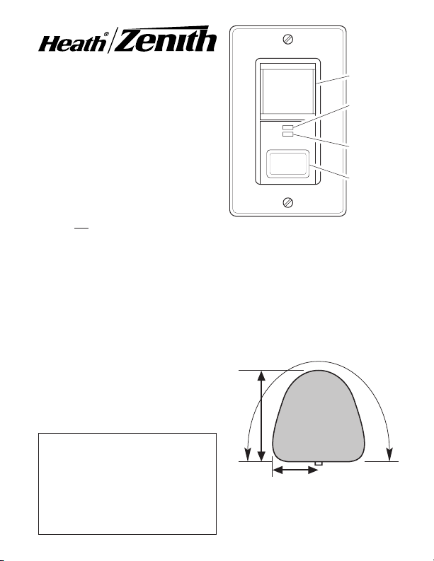
Figure 1 - Typical View of Coverage
INSTALLATION
SELECT A LOCATION
30 ft. (9.1 m)
15 ft. (4.6 m)
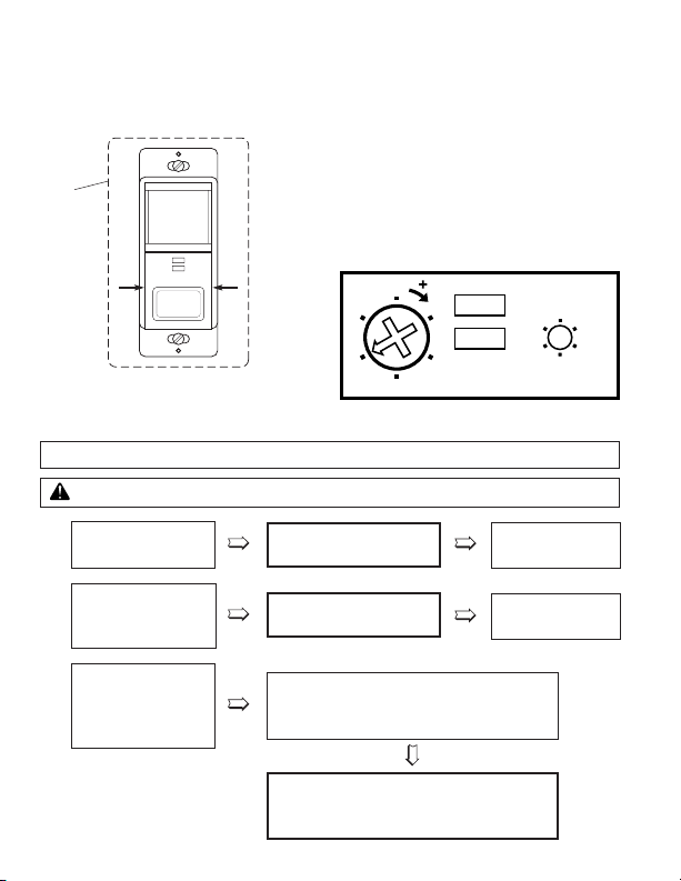
Motion Sensor
Motion Sensor
ON/OFF LED
Indicator
Switch Power
LED Indicator
Motion Sensor
ON/OFF
Button
180°
Page 2
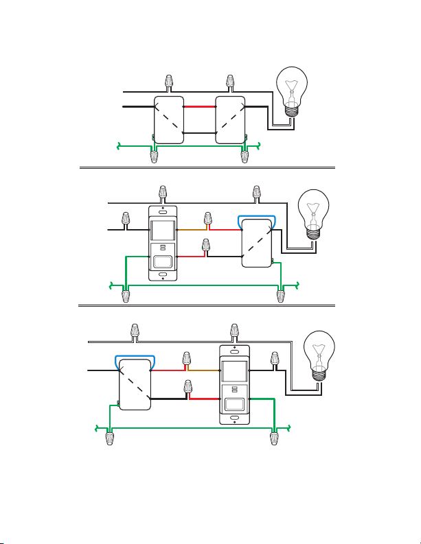
6108 SWITCH 1ST IN CIRCUIT
GREEN
(Ground)
WHITE
FROM
POWER
SOURCE
BLACK BLACK
WHITE
RED
(In Wall)
BROWN
BLACK
EXISTING
3-WAY SWITCH
ADD JUMPER WIRE
6108
RED
(From 6108)
WHITE
BLACK
*COMMON
TYPICAL 3-WAY INSTALLATION
GREEN
(Ground)
WHITE
FROM
POWER
SOURCE
BLACK
WHITE
BLACK
WHITE
BLACK
*COMMON *COMMON
6108 SWITCH 2ND IN CIRCUIT
WHITE
FROM
POWER
SOURCE
BLACK
BLACK
WHITE
RED
(In Wall)
BROWN
BLACK
EXISTING
3-WAY SWITCH
ADD JUMPER WIRE
6108
RED
(From 6108)
WHITE
BLACK
*COMMON
GREEN
(Ground)
RED
(In Wall)
SEE PAGES 3 THROUGH 5 FOR DETAILED INSTRUCTIONS FOR INSTALLING
AND WIRING THE 6108 WALL SWITCH.
*COMMON-Used for illustrative purposes only. Check Your Switch. The common may be in a different
location, depending on the brand of your switch.
RED is used to represent the second wire between two standard three-way switches. This may not be
the color used in all installation. If you are not sure about your wiring, call an electrician for instal
lation help. There is also a RED wire on the 6108 switch. Check the instructions above closely and
do not confuse the two.
2
-
598-1233-02
Page 3

WARNING: Turn power off at the
circuit breaker before wiring.
INSTALLING SENSOR
A “3-way” circuit controls lights from two separate
switches. Select a 3-way circuit that controls a light
or an outlet to a lamp.
IMPORTANT: Total lighting must be from
25 to 500 watts incandescent, or 60 to
400 watts fluorescent. Less wattage than
the minimum may not allow the control to work
properly. The switch selected for replacement
should be in a place that can detect motion in
the desired area.
For easier re-wiring later, mark the house wiring
with tape indicating where the wire had been
connected.
In the following section you will install a jumper
wire at one 3-way switch and replace the other
switch with the 6108.
Note: The existing 3-way switch will be referred
to as the “Remote Switch” throughout the rest of
the installation manual.
Before the Installation
Add Jumper At Remote 3-Way Switch
A jumper wire between the common wire and
one of the switched wires is used to supply
power to the 6108 regardless of the position of
the remote switch.
1. Remove remote switch from the junction box.
2. Connect the jumper wire to the common lug
(usually labeled on the switch) and to either
one of the two switched lugs. If you're not sure
which lug is common, install the jumper on any
two of the wires, and test the jumper according
to the flow chart on page 5.
Jumper
*Common
Switch Screw
Hot Wire
* The switch may indicate the common or the
color of screw may be different for the common.
Figure 2 - Connecting Jumper to Remote
Switch
Wire
To Brown wire
of 6108 (note
color)
To Red wire
of 6108
(note color)
598-1233-02
3
Page 4
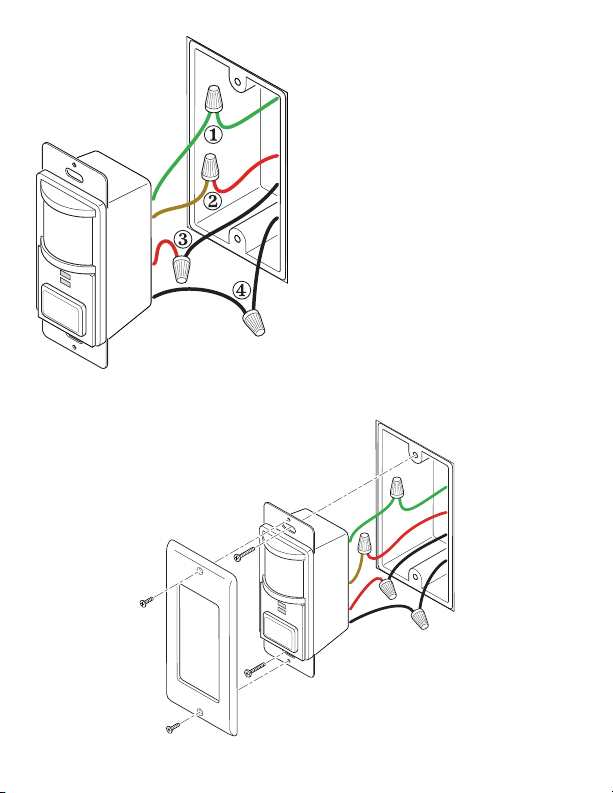
Figure 3 - Wiring the 6108 Wall Switch
Remove and disconnect the old switch. Note: If you
can not tell which wire is common, etc., connect
the wires in the following steps as best you can,
then follow the test on the next page. The following
steps are in the same order as the numbers in the
wiring diagram (see Figure 3).
1. Connect the green motion sensor wire to the
2. Connect the brown motion sensor wire to
3. Connect the red motion sensor wire to the
4. Connect the black motion sensor wire to the
IMPORTANT: Before installing sensor into
5. Mount sensor into junction box using two large
6. Turn the circuit breaker on.
Replace Other Switch
house ground wire.
the jumpered wire coming from the remote
switch.
non-jumpered wire coming from the remote
switch.
common wire removed from the replaced
switch.
junction box, make sure there is no wire exposed
at each connection.
mounting screws provided (see Figure 4).
Figure 4 - Mounting the 6108 Wall Switch
4
598-1233-02
Page 5
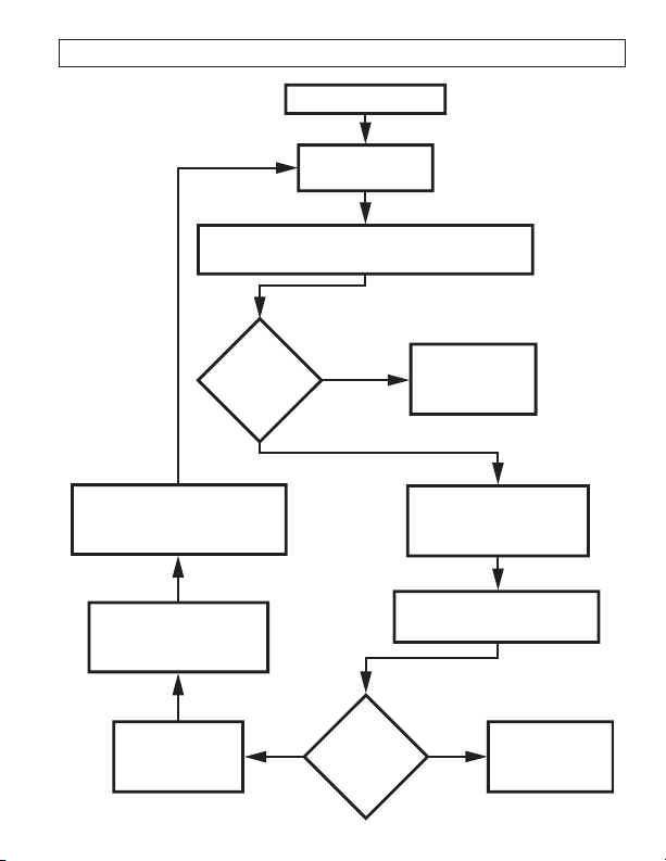
TEST FOR CORRECT COMMON WIRE CONNECTION
Re-install the switch.
Turn
the circuit
break
er back on.
Leaving the jumpered switch in one position,
flip the other 3-way switch on and off.
Lights
turn on
and off.
Lights
turn on
and off.
Jumper is
correct. Go
to next page.
Flip the switch with the
jumper wire to the
other position.
Flip the unjumpered switch
on and off.
Jumper is
correct. Go
to next page.
Move one end of the jumper
wire to the previously
unconnected terminal.
Remove the jumpered
switch from the
junction box.
Turn the power
off at the
circuit breaker.
Yes
Ye
sNo
No
598-1233-02
5
Page 6
1. Remove the decorative cover plate (secured by
T I M E
5
25
10
15
1
Test
two small screws).
2. Pinch control panel cover at the indicated points
as shown in Figure 5. Pull to remove cover.
Decorative
Cover
Plate
Pinch Here
Figure 5 - Removing Control Panel Cover
TESTING
Pinch Here
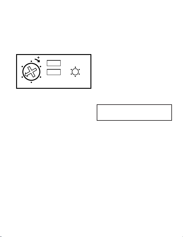
3. For test purposes, use a small, phillips screwdriver to turn the TIME control to the TEST
(5 second) position (see Figure 6). Turn the
power back on at the circuit breaker.
4. Verify the switch has power. The bottom LED
will be lit.
5. Allow the sensor to stabilize (about 1 minute).
The sensor is ready to detect motion.
6. Push the ON/OFF button. The lights and mo
tion sensor will turn on. The lights will remain
on as long as the sensor detects motion or the
ON/OFF button is pushed again. The lights
will turn off 5 seconds after motion stops.
Figure 6 - Control Panel
TROUBLESHOOTING WIRING CONNECTIONS
WARNING: Turn power off at the circuit breaker before rewiring.
-
If light does not
1.
turn on:
If light turns on in
only one position
2.
of remote switch:
If light turns
on with remote
3.
switch in either
position:
Exchange* Control’s
Red ⇔ Black wires.
Exchange* Control’s
Red ⇔ Brown wires.
Test again. Go
to 2 or 3.
Test again. Go
to 1 or 3.
Wait for the unit to warm up (up to 1
minute). If the remote switch can turn
the lights on, it’s OK. Otherwise:
Exchange* Control’s
Black
⇔ Brown wires. Remove the
tape. Go to the next page.
6
598-1233-02
Page 7
ADJUSTMENTS
T I M E
5
25
10
15
1
Test
There are 6 preset selections for the amount of
time the lights stay on: Test (5 seconds), 1, 5, 10,
15, and 25 minutes. Use a small, phillips screw
driver to adjust the TIME control (see Figure 7).
Turn the TIME control until it “snaps” into the
desired time position.
Figure 7 - Control Panel
TIME
COMPLETING
1. Replace control panel cover and attach the deco-
2. Push the ON/OFF button. Verify the switch turns
3. Push the ON/OFF button again and verify the
4. Push the ON/OFF button again to turn lights and
INSTALLATION
rative wall plate (see Figure 4). In installations
where the Heath®/Zenith motion sensor switch
is combined with other switches or outlets on
an expanded box, you will need to purchase a
combination wall plate. Various combination
wall plates are available at home centers and
electrical supply stores.
on the lights and the top LED is on.
lights turn off and the top LED is off.
sensor on. Leave the room or stay completely
still for the amount of time you selected for
the lights to stay on. Verify the lights turn off
at the desired time.
Note: The motion sensor requires a 2
second delay when switching off and
on using the ON/OFF button.
Electrical Input ................................................................................................................ 120V, 60 Hz.
Fluorescent* Load .................................................... 30 Watts minimum, Up to 400 Watts Maximum
Motor Load ....................................................................................................Up to 1/8 HP Maximum
Incandescent ..........................................................................Up to 500 Watts Maximum at 120VAC
On-Time .............................................................Selectable, approximately 5 seconds to 25 minutes
Coverage ................................. up to 15 ft. (4.6 m) at 180°, up to 30 ft. (9.1 m) in front of the sensor
*Designed for use with standard 3 ft./30 watt and 4 ft./40 watt rapid-start fluorescent tubes.
598-1233-02
SPECIFICATIONS
7
Page 8

TROUBLESHOOTING
SYMPTOM POSSIBLE CAUSE SOLUTION
Light does not come
on.
Light does not turn off.
Lights do not stay on
as desired.
Remote switch does
not work.
If you experience a problem, follow this guide. You may also want to visit our Web site at: www.desatech.com.
If the problem persists, call* for assistance at
also write* to:
DESA Specialty Products™
P.O. Box 90004, Bowling Green, KY 42102-9004
ATTN: Technical Service Specialty Products
* If contacting Technical Service, please have the following information available: Model Number, Date of
Purchase, and Place of Purchase.
1. Circuit breaker or fuse is
turned off.
2. If the lamp being controlled
has another switch, it may
be turned off.
3. Bulb is burned out.
4. Poor connection.
5. ON /O FF bu tt on no t
pushed.
6. Control may be wired
wrong.
1. Switch is being triggered
by air vent or other heat
source.
2. Motion is still present.
3. Delay set by TIME control
has not expired.
4. Control may be wired
wrong.
1. Motion has stopped in the
room.
2. TIME control is set for too
short a delay.
1. Control may be wired
wrong.
TECHNICAL SERVICE
(Do Not Send Products)
1-800-858-8501, 7:30 AM to 4:30 PM CST (M-F). You may
NO SERVICE PARTS AVAILABLE FOR THIS PRODUCT
1. Turn circuit breaker on.
2. Turn other switch on.
3. Replace light bulb.
4. Verify all wiring connec
tions.
5. Press the ON/OFF button.
6. See Troubleshooting Wiring
Connections, page 6.
1. Move switch to other switch
location or determine the
source triggering the switch
and alter air flow.
2. Make sure there is no motion
during TIME control period.
3. Set switch TIME control to
shorter time period.
4. See Troubleshooting Wiring
Connections, page 6.
1. Continue movement.
2. Set switch TIME control to
longer time period.
1. See Troubleshooting Wiring
Connections, page 6.
-
8
598-1233-02
Page 9

This is a “Limited Warranty” which gives you specific legal rights. You may also have other rights which vary from
state to state or province to province.
For a period of five years from the date of purchase, any malfunction caused by factory defective parts or
workmanship will be corrected at no charge to you.
Not Covered - Repair service, adjustment and calibration due to misuse, abuse or negligence, light bulbs, batteries,
and other expendable items are not covered by this warranty. Unauthorized service or modification of the product
or of any furnished component will void this warranty in its entirety. This warranty does not include reimbursement
for inconvenience, installation, setup time, loss of use, unauthorized service, or return shipping charges.
This warranty covers only DESA Specialty Products™ assembled products and is not extended to other equipment
and components that a customer uses in conjunction with our products.
THIS WARRANTY IS EXPRESSLY IN LIEU OF ALL OTHER WARRANTIES, EXPRESS OR IMPLIED, INCLUDING
ANY WARRANTY, REPRESENTATION OR CONDITION OF MERCHANT ABILITY OR THAT THE PRODUCTS
ARE FIT FOR ANY PARTICULAR PURPOSE OR USE, AND SPECIFICALLY IN LIEU OF ALL SPECIAL,
INDIRECT, INCIDENTAL, OR CONSEQUENTIAL DAMAGES.
REPAIR OR REPLACEMENT SHALL BE THE SOLE REMEDY OF THE CUSTOMER AND THERE SHALL
BE NO LIABILITY ON THE PART OF DESA SPECIALTY PRODUCTS™ FOR ANY SPECIAL, INDIRECT,
INCIDENTAL, OR CONSEQUENTIAL DAMAGES, INCLUDING BUT NOT LIMITED TO ANY LOSS OF BUSINESS
OR PROFITS, WHETHER OR NOT FORESEEABLE. Some states or provinces do not allow the exclusion or
limitation of incidental or consequential damages, so the above limitation or exclusion may not apply to you.
Proof of purchase is required for warranty claims.
DESA Specialty Products™ reserves the right to discontinue products and to change specifications at
any time without incurring any obligation to incorporate new features in products previously sold.
FIVE YEAR LIMITED WARRANTY
598-1233-02
9
Page 10

Detector de
movimiento
Conforme al título 24
INTERRUPTOR
TRIDIRECCIONAL DE
PARED Y DECTECTOR
DE MOVIMIENTO
6108
El detector de movimiento 6108 cumple con los reglamentos Título 24 de California para cocinas, cuartos de
baño, lavanderías, pasillos, comedores y dormitorios.
El pulsador enciende o apaga manualmente las luces
y activa o desactiva al detector de movimiento. Luego
de detectar movimiento, el detector mantiene las
luces encendidas durante el tiempo calibrado. Luego
el detector de movimiento y las luces son apagados
debiendo ser encendidos de nuevo pulsando el botón
ON antes de la detección del movimiento.
La unidad goza de una excelente sensibilidad y
de un gran alcance de detección de 180°. Se lo
puede usar con luz incandescente como también
con luz fluorescente. Dos LEDs permiten una fácil
identificación del estado.
Su instalación es tan fácil como el cambiar un
interruptor de pared.
Algunas normas exigen que la instalación
la realice un electricista calificado.
Elementos incluidos en el paquete:
• Interruptor del detector • Placa cubertora
• 4 Conectores de alambre
• 2 Tornillos pequeños •
• Manual del propietario • 1 Cable puente
Sus características incluyen:
• Angulo de detección de movimiento de 180°
• Seleccionable ON-TIME de 5 segundos a 25
minutos
• Funciona con alumbrado incandescente y
fluorescente
• Funciona con motores de hasta 1/8 hp (caballo
de fuerza)
• El detector de movimiento se enciende o apaga
al pulsar el botón
© 2006 DESA Specialty Products™ 598-1233-02 S
2 Tornillos grandes
El detector es más sensitivo al movimiento que
atraviesa por el frente que al que se dirige hacia
el detector.
El sensor detecta calor en movimiento y po
siblemente las fuentes de calor que cambian
rápidamente de temperatura. Por lo tanto, para
evitar falsas alarmas, no coloque el detector frente
a acondicionadores de aire, calentadores u otras
fuentes de calor o de frío.
Figura 1 - Vista típica de la cobertura
10
INSTALACION
ESCOJA UN LUGAR
9.1 m
4.6 m
Indicador LED
ENCENDIDO/
APAGADO del
detector de
movimiento
Indicador LED
del interruptor
de alimentación
Botón
ENCENDIDO/
APAGADO del
detector de
movimiento
180°
598-1233-02
-
Page 11

INTERRUPTOR 6108 1ro EN EL CIRCUITO
VERT
(Terre)
BLANCO
NEGRO NEGRO
BLANCO
RO
JO
(en la
pared)
MARRÓN
NEGRO
INTERRUPTOR
DE 3-VÍAS EXISTENTE
AÑADA EL
CONDUCTOR PUENTE
6108
RO
JO
(Desde
el 6108)
BLANCO
NEGRO
*COMÚN
INSTALACION TÍPICA DE TRES VÍAS
VERT
(Terre)
*COMÚN *COMÚN
INTERRUPTOR 6108 2do EN EL CIRCUITO
BLANCO
NEGRO
NEGRO
BLANCO
RO
JO
(en la
pared)
MARRÓN
NEGRO
INTERRUPTOR
DE 3-VÍAS EXISTENTE
AÑADA EL
CONDUCTOR PUENTE
6108
RO
JO
(Desde
el 6108)
BLANCO
NEGRO
*COMÚN
VERT
(Terre)
BLANCO BLANCO
BLANCO
NEGRO
NEGRO
NEGRO
DE LA
FUENTE DE
ALIMENTACIÓN
DE LA
FUENTE DE
ALIMENTACIÓN
DE LA
FUENTE DE
ALIMENTACIÓN
ROJO
(en la
pared)
VEA EN LAS PÁGINAS 12 A 14 LAS INSTRUCCIONES DETALLADAS PARA LA
INSTALACIÓN Y CABLEADO DEL INTERRUPTOR DE PARED 6108.
*COMÚN- Usado sólo por razones ilustrativas. Revise su interruptor. El común puede estar en una
ubicación diferente, dependiendo de la marca de su interruptor.
ROJO- Se usa para representar el segundo conductor entre los dos interruptores estándar de 3-vías.
Este puede no ser el color usado en toda la instalación. Si no está seguro de su cableado, llame a un
electricista para que le ayude en la instalación. Hay también un conductor ROJO en el interruptor 6108.
Revise con más detenimiento las instrucciones de arriba para no confundir los dos.
598-1233-02
11
Page 12

ADVERTENCIA: Apague la energía
en el cortacircuitos antes de hacer las
conexiones.
INSTALACION DEL DETECTOR
Un circuito “tridireccional” es un circuito de luz
controlado desde dos interruptores separados.
Escoja un circuito de 3 direcciones que controle
una luz o un enchufe de lámpara.
IMPORTANTE
estar entre 25 a 500 vatios incandescentes,
o entre 60 a 400 vatios fluorescentes. Un
vatiaje menor del mínimo no permitirá que el control
funcione correctamente. El interruptor seleccionado
para cambiar debería estar en un lugar que puede
detectar movimiento en la área deseada.
Para facilitar la instalación y el cableado más
tarde, use cinta elécrica en los cables y marque
de dónde viene cada uno.
En la siguiente sección usted instalará un puente de
alambre en el un interruptor de 3-vías y reemplazará
el otro interruptor con el 6108.
Nota: Al interruptor existente de 3 direcciones se
le llamará “interruptor remoto” durante el resto del
manual de instalación.
Antes de la instalación
: El alumbrado total debe
Una el cable de conexión al interruptor
tridireccional a control remoto
Se usa un cable de conexión entre el alambre
común y uno de los alambres con interruptor para
suplir energía al 6108 cualquiera sea la posición
del interruptor a control remoto.
1. Quite el interruptor a control remoto de la caja
de empalme.
2. Conecte el puente de alambre al borne común
(generalmente identificado en el interruptor) y
a cualquiera de los otros bornes del interruptor.
Si no está seguro cual orejeta es común, instale
un puente entre cualquier par de alambres y
pruebe el puente según el diagrama de flujo
de la página 14.
Alambre
*Tornillo
común del
interruptor
Cable caliente
*El interruptor debe indicar el común o el
color del tornillo asignado al común debe ser
diferente.
Figura 2 - Conexión del puente al interruptor
remoto
puente
Al alambre
marrón del 6108
(Note el color)
Al alambre rojo
del 6108 (Note
el color)
12
598-1233-02
Page 13

Figura 3 - Cableado del interruptor de pared
6108
Instale el Detector de Movimiento en el otro
Quite y desconecte el interruptor viejo. Nota:
Si no sabe cuál es el alambre común, etc., en los
pasos que siguen, conecte los alambres lo mejor
que pueda y haga luego la prueba que se indica
en la página siguiente. Los siguientes pasos están
en el mismo orden que los números del esquema
de conexiones (vea la Figura 3).
1. Conecte el alambre verde del detector de
movimiento al alambre de conexión a tierra
de la casa.
2. Conecte el alambre marrón del detector de
movimiento al alambre puente del interruptor
remoto.
3. Conecte el alambre rojo del detector de mo
vimiento al alambre sin puente que viene del
interruptor remoto.
4. Conecte el alambre negro del detector de
movimiento al alambre común retirado del
interruptor reemplazado.
IMPORTANTE: Antes de instalar el detector
en la caja de empalmes, asegúrese que no haya
alambre expuesto en cada conexión.
5. Monte el detector en la caja de empalmes con
los dos tornillos de montaje provistos (vea la
Figura 4).
6. Conecte el disyuntor.
interruptor
-
Figura 4 - Montaje del interruptor de pared 6108
598-1233-02
13
Page 14

PRUEBA PARA LA CONEXIÓN CORRECTA DE UN CABLE COMÚN
Reinstale el interruptor.
Prenda de nuev
o el
cortacircuitos.
Dejando el cable con puente en una posición,
prenda y apague el otro interr
uptor tridireccional.
La luz
se prende y
se apaga.
El puente está
bien. Vaya a la
página siguiente.
Mueva el interruptor con
el cable de puente a la
otra posición.
Prenda y apague el
interruptor sin puente.
Mueva un extremo del cable
de puente al terminal anterior
desconectado.
Quite el interruptor
con puente de la
caja de empalmes.
Apague la
energía en el
cortacircuitos.
La luz
se prende y
se apaga.
El puente está
bien. Vaya a la
página siguiente.
Sí
SíNo
No
14
598-1233-02
Page 15

1. Quite la placa cubertora decorativa (asegurada
T I M E
5
25
10
15
1
Test
con dos tornillos decorativos).
2. Apriete la tapa del panel de control en los puntos
indicados en la Figura 5. Hale para retirar la
tapa.
3. Para probar, use un destornillador Phillips
pequeño y gire el control de TIEMPO a la
posición PRUEBA (TEST) (5 segundos) (vea
la Figura 6). Vuelva a conectar el disyuntor.
Placa
cubertora
decorativa
PRUEBA
4. Verifique que el interruptor tiene energía. El
LED inferior estará encendido.
5. Deje que el detector se estabilice (más o menos
1 minuto). El detector está listo para detectar
movimiento.
6. Pulse el botón ENCENDIDO/APAGADO. Se
encenderán las luces y el detector de movimiento. Las luces permanecerán encendidas todo el
tiempo que se detecta movimiento o si se pulsa
de nuevo el botón ENCENDIDO/APAGADO.
Las luces se apagan 5 segundos después que
detenerse el movimiento.
Apriete
aquí
Figura 5 - Cómo quitar la tapa del panel de
control
Apriete
aquí
Figura 6 - Panel de control
ANÁLISIS DE AVERÍAS EN EL CABLEADO
ADVERTENCIA: Desconecte la energía en el disyuntor antes de volver a cablear.
Si la luz no se
1.
Si la luz se prende
solo cuando el
interruptor a control
2.
remoto está hacia
arriba o hacia abajo:
interruptor a control
3.
remoto en cualquier
598-1233-02
prende:
Si luz con el
posición:
Cambie* los alam-
bres Rojos y Negros
del Control.
Cambie* los alam-
bres Rojos y Marrón
del Control.
Espere hasta que el aparato se calienta
(hasta 1 min.). Si el interruptor remoto puede
prender la luz, está bien. De otra for ma:
Cambie* los controles Cables Negro ⇔ Marrón Quite la cinta. Vaya
a la siguiente página.
15
Pruebe de
nuevo. Vaya al 2
ó al 3.
Pruebe de
nuevo. Vaya al 1
ó al 3.
Page 16

AJUSTES
T I M E
5
25
10
15
1
Test
Hay 6 ajustes precalibrados para el lapso de tiempo
que las luces permanecen encendidas: Prueba
(5 segundos), 1, 5, 10, 15 y 25 minutos. Use un
destornillador Phillips pequeño para regular el
control de TIEMPO (Vea la Figura 7). Gire el
control hasta que se “coloque a presión” en la
posición de tiempo deseada.
Figura 7 - Panel de control
TIEMPO
INSTALACION COMPLETA
1. Recoloque la tapa del panel de control e instale la
placa ornamental de pared (Vea la Figura 4). En
las instalaciones donde se combine el interruptor
detector de movimiento Heath®/Zenith con otros
interruptores o enchufes en una caja extendida,
se necesitará comprar una placa combinadora
de pared. Varias placas combinadoras de pared
se pueden encontrar en los centros comerciales
para el hogar y‚ en las tiendas de aparatos elé
ctricos.
2. Pulse el botón ENCENDIDO/APAGADO.
Verifique que el interruptor enciende las luces y
que la luz del LED superior esté encendida.
3. Pulse de nuevo el botón ENCENDIDO/APA
GADO y verifique que las luces se apaguen y
que la luz del LED superior esté apagada.
4. Pulse de nuevo el botón ENCENDIDO/APAGADO para encender las luces y el detector.
Salga de la habitación o permanezca completamente quieto durante el lapso de tiempo
que seleccionó para que las luces queden
encendidas. Verifique que las luces se apaguen
en el tiempo deseado.
NOTA: El detector de movimiento
requiere 2 segundos de retardo cuando,
utiliza ndo el botón E NCENDID O/
APAGADO, cambia entre apagado y
encendido.
-
Entrada eléctrica ................................................................................................................120V, 60 Hz.
Carga Fluorescente .............................................................. 30 Vatios Mín., Hasta 400 Vatios Máximo
Carga del motor ..................................................................................................
Incandescente ...............................................................................................Hasta 500 Vatios Máximo
Duración ...........................................................Seleccionable ON-TIME de 5 segundos a 25 minutos
Alcance ..................................................................Hasta 4.6 m a 180°, hasta 9.1 m frente al detector
*Diseñado para ser usado con tubos fluorescentes de arranque rápido de 3 pies/30 vatios y de 4
pies/40 vatios.
ESPECIFICACIONES
Hasta 1/8 HP Máximo
16
598-1233-02
Page 17

GUIA DE SOLUCION DE PROBLEMAS
SÍNTOMA CAUSA PROBABLE SOLUCIÓN
La luz no enciende.
La luz no apaga.
Las luces no
permaneces
encendidas como
se desea.
El interruptor
remoto no funciona.
Si tiene algún problema por favor siga esta guía. Lo sentimos, pero no podemos contestar preguntas
en español por teléfono. Usted puede también escribir* a:
DESA Specialty Products™
P.O. Box 90004, Bowling Green, KY 42102-9004
* Si se llama al Servicio Técnico, por favor tener lista la siguiente información: Número de Modelo,
Fecha de compra y Lugar de compra.
NO HAY PIEZAS DE SERVICIO DISPONIBLES PARA ESTE PRODUCTO
1. El disyuntor o el fusible está
desconectado.
2. Si la lámpara está controlada
desde otro interruptor, este puede
estar apagado.
3. Bombilla quemada.
4. Conexión deficiente.
5. El botón ENCENDIDO/APA
GADO no se ha pulsado.
6. El co ntrol d ebe estar ma l
cableado.
1. El interruptor se está siendo
activado por una ventosa de aire
u otra fuente de calor.
2. El movimiento aún está presente.
3. El retardo fijado por el control
de TIEMPO aún no termina.
4. El control debe estar mal cablea
do.
1. Ya no hay movimiento en la
habitación.
2. El control de TIEMPO está
calibrado a un lapso muy corto
de retardo.
1. El co ntrol d ebe estar ma l
cableado.
SERVICIO TÉCNICO
(No enviar los productos)
1. Conecte el disyuntor.
2. Encienda el otro interruptor.
3. Cambie la bombilla.
4. Verifique todas las conexiones del
cableado.
-
5. Presione el botón ENCENDIDO/
APAGADO.
6. Vea Anális is de a verías en el
cableado, página 15.
1. Mueva el interruptor a otro lugar
o determine la fuente que activa
al interruptor y cambie el flujo de
aire.
2. Asegúrese que no haya movimiento
durante el lapso del control de
TIEMPO.
3. Ponga el control de tiempo en un
lapso de tiempo más corto.
-
4. Vea Anális is de a verías en el
cableado, página 15.
1. Haga que el movimiento continúe.
2. Calibre el control de TIEMPO a un
lapso mayor.
1. Vea Anális is de a verías en el
cableado, página 15.
598-1233-02
17
Page 18

Esta es una “Garantía Limitada” que le da a Ud. derechos legales específicos. Usted puede también tener otros
derechos que varían de estado a estado o de provincia a provincia.
Por un período de 5 años desde la fecha de compra, cualquier mal funcionamiento ocasionado por partes
defectuosas de fábrica o mano de obra será corregido sin cargo para Ud.
No cubierto - Servicio de reparación, ajuste y calibración debido al mal uso, abuso o negligencia, bombillas, baterías,
u otras partes fungibles no están cubiertas por esta garantía. Los Servicios no autor izados o modificaciones del
producto o de cualquier componente que se provee invalidarán esta garantía en su totalidad. Esta garantía no
incluye reembolso por inconveniencia, instalación, tiempo de instalación, perdida de uso, servicio no autorizado,
o costos de transporte de retorno.
Esta garantía cubre solamente los productos ensamblados por DESA Specialty Products™ y no se extiende a
otros equipos o componentes que el consumidor usa junto con nuestros productos.
ESTA GARANTÍA ESTÁ EXPRESAMENTE EN LUGAR DE OTRAS GA RANTÍAS, EXPRESADAS O
SOBREENTENDIDAS, INCLUYENDO CUALQUIER GARANTÍA, REPRESENTACIÓN O CONDICIÓN DE
COMERCIABILIDAD O QUE LOS PRODUCTOS SE ADAPTEN PARA CUALQUIER PROPÓSITO O USO EN
PARTICULAR, Y ESPECIFICAMENTE EN LUGAR DE TODOS LOS DAÑOS ESPECIALES, INDIRECTOS,
INCIDENTALES Y CONSECUENTES.
LA REPARACIÓN O EL REEMPLAZO DEBERÍA SER LA ÚNICA SOLUCIÓN DEL CLIENTE Y NO HABRÁ
RESPONSABILIDAD POR PARTE DE DESA SPECIALTY PRODUCTS™ POR CUALQUIER DAÑO ESPECIAL,
INDIRECTO, INCIDENTAL O CONSECUENTE, INCLUIDOS PERO NO LIMITADOS A CUALQUIER PÉRDIDA
DE NEGOCIO O GANACIAS SEAN O NO PREVISIBLES. Algunos estados o provincias no permiten la exclusión
o limitación de daños incidentales o consecuentes, de modo que la limitación o exclusión arriba indicada puede
que no se aplique a Ud. Para reclamos por la garantía se requiere la prueba de compra.
DESA Specialty Products™ se reserva el derecho de descontinuar productos y de cambiar especificaciones
a cualquier momento sin incurrir en ninguna obligación de tener que incorporar nuevas características en
los productos vendidos con anterioridad.
GARANTÍA LIMITADA A 5 AÑOS
18
598-1233-02
Page 19

Détecteur de
mouvement
Conforme au Title 24
Interrupteur mural à
3 voies avec détecteur de mouvement
6108
L’interrupteur mural à détecteur de mouvement
6108 est conforme à la réglementation californienne
Title 24 pour ce qui est des cuisines, salles de bain,
salles de lavage, entrées, salle à dîner et chambres
à coucher. Le bouton-poussoir permet d’allumer
ou d’éteindre l’éclairage et
le détecteur de mouvement. Ce dernier garde
l’éclairage allumé pendant une période prédéfinie
après la détection d’un mouvement. Le détecteur
de mouvement et l’éclairage sont ensuite fermés et
doivent être réactivés en appuyant sur l’interrupteur
avant qu’un mouvement ne puisse être détecté.
L'appareil possède une excellente sensibilité et
un angle de détection de 180°. Il peut être utilisé
pour l’éclairage incandescent ou fluorescent. Deux
voyants à DEL permettent de facilement connaître
l’état de fonctionnement des composantes.
Son installation est aussi simple que le remplacement d'un interrupteur mural.
Certains codes de l’électricité exigent que
l’installation soit confiée à un électricien
qualifié.
L’emballage contient :
• Interrupteur à détecteur
• Plaque murale • 4 serre-fils
• 2 petites vis • 2 grandes vis
• 1 cavalier • Guide du propriétaire
Ses caractéritisques comprennent :
• Angle de détection de mouvement de 180°
• Temps en circuit (ON-TIME) réglable de 5
secondes à 25 min
• Fonctionne avec l’éclairage incandescent ou
fluorescent
• S'utilise avec moteurs jusqu'à 1/8 hp
• Le bouton-poussoir permet d’activer et de
désactiver le détecteur de mouvement
© 2006 DESA Specialty ProductsMC 598-1233-02 F
598-1233-02
d’activer ou désactiver
INSTALLATION
DÉTERMINER L'EMPLACEMENT
Le détecteur est plus sensible au mouvement
transversal qu'au mouvement perpendiculaire
au détecteur.
Le détecteur perçoit la chaleur en mouvement et
possiblement les sources de chaleur qui changent
rapidement de température. Par conséquent, pour
éviter les déclenchements intempestifs, éviter
de monter le détecteur à un endroit où il serait
orienté directement vers les climatiseurs d'air,
les chaufferettes et autres sources de chaleur
ou de froid.
9,1 m
4,6 m
Figure 1 - Zone de couverture classique
19
Voyant à DEL
d’ACTIVATION/
DÉSACTIVATION
du détecteur de
mouvement
Voyant à DEL de
l’interrupteur
Bouton
d’ACTIVATION/
DÉSACTIVATION
du détecteur de
mouvement
180°
Page 20

PREMIER INTERRUPTEUR 6108 DU CIRCUIT
VERT
(mise à la terre)
BLANC
ALIMENTATION
SECTEUR
NOIR NOIR
BLANC
RO
UGE
(dans le
mu
r)
BRUN
NOIR
INTERRUPTEUR À
3 VOIES EN PLACE
AJOUTER UN
CAVALIER
6108
ROUGE
(du 6108)
BLANC
NOIR
*NEUTRE
INSTALLATION CLASSIQUE À 3 VOIES
VERT
(mise à la terre)
BLANC
ALIMENTATION
SECTEUR
NOIR
BLANC
NOIR
BLANC
NOIR
*NEUTRE *NEUTRE
SECOND INTERRUPTEUR 6108 DU CIRCUIT
BLANC
ALIMENTATION
SECTEUR
NOIR
NOIR
BLANC
RO
UGE
(dans le
mu
r)
BRUN
NOIR
INTERRUPTEUR À
3 VOIES EN PLACE
AJOUTER UN
CAVALIER
6108
RO
UGE
(du 6108)
BLANC
NOIR
*NEUTRE
VERT
(mise à la terre)
ROUG
E
(dans le
mu
r)
CONSULTEZ LES PAGES 21 À 23 POUR DES DIRECTIVES DÉTAILLÉES SUR
L’INSTALLATION ET LE CÂBLAGE DE L’INTERRUPTEUR MURAL 6108.
*NEUTRE : Utilisé aux fins d’illustration seulement. Vérifiez l’interrupteur. Le fil neutre pourrait être
à un autre endroit selon la marque de l’interrupteur.
Le ROUGE désigne le second fil reliant deux interrupteurs à 3 voies standard. Il se peut que ce ne
soit pas la couleur utilisée dans toutes les installations. Si vous n’êtes pas certain du câblage, appelez
un électricien pour obtenir de l’aide. L’interrupteur 6108 comporte aussi un fil ROUGE. Lisez les
directives ci-dessus avec soin pour éviter de confondre les deux fils.
20
598-1233-02
Page 21

MISE EN GARDE : Coupez le courant
au niveau du disjoncteur avant de
raccorder les fils.
INSTALLATION DU CAPTEUR
Un circuit à 3 voies permet de commander l’éclairage au moyen de deux interrupteurs distincts.
Sélectionnez un circuit à 3 voies qui commande
un luminaire ou une prise à laquelle est branchée
une lampe.
IMPORTANT : La puissance totale de
l’éclairage doit varier entre 25 et 500 W
pour des ampoules incandescentes et
entre 60 et 400 W pour des ampoules
fluorescentes. Une puissance inférieure au
minimum indiqué pourrait nuire au fonctionnement
de l’interrupteur. L’interrupteur à remplacer doit
être situé à un endroit permettant au détecteur de
mouvement de déceler les mouvements dans la
zone souhaitée.
Pour faciliter le rebranchement des fils, identifiez
chacun des fils au moyen d’un ruban adhésif en
précisant à quel endroit il était raccordé.
Dans la section qui suit, vous installerez un cavalier
sur l’un des interrupteurs à 3 voies et remplacerez
l’autre interrupteur par un 6108.
Note : L’interrupteur à 3 voies en place sera désigné
par l’expression « interrupteur distant » dans le
reste du guide d’installation.
Avant l’installation
Ajout d’un cavalier sur l’interrupteur à 3
Un cavalier est ajouté entre le fil neutre et l’un
des fils de l’interrupteur pour fournir du courant
au 6108 quelle que soit la position de l’interrup
teur distant.
1. Retirez l’interrupteur distant de la boîte de
raccordement.
2. Branchez le cavalier à la languette du fil neutre
(habituellement identifiée sur l’interrupteur)
puis à l’une ou l’autre des deux languettes de
l’interrupteur. Si vous n’êtes pas certain de
savoir quelle est la bonne languette de contact,
installez le cavalier sur n’importe lequel des
deux fils, puis faites l’essai du cavalier confor
mément à ce qui est indiqué au diagramme de
la page 23.
*Vis du fil
neutre de
l’interrupteur
Fil sous
tension
*Cet interrupteur peut indiquer le fil neutre ou
la couleur de la vis peut être différente pour le
fil neutre.
Figure 2 - Raccordement du cavalier à l’inter
rupteur distant
voies distant
Cavalier
Vers le fil brun du
6108 (remarquez
la couleur)
Vers le fil rouge du
6108 (remarquez
la couleur)
-
-
-
598-1233-02
21
Page 22

Figure 3 - Raccordement de l’interrupteur
mural 6108
Remplacement de l’autre interrupteur
Débranchez et retirez l’ancien interrupteur. Note :
Si vous ne savez pas quel fil est le neutre, etc.,
branchez les fils des étapes qui suivent du mieux
que vous le pouvez, puis effectuez les essais de la
page suivante. Les étapes qui suivent portent les
mêmes numéros que les chiffres du diagramme
de câblage (voir la Figure 3).
1. Branchez le fil vert du détecteur de mouvement
au fil de mise à la terre de l’alimentation.
2. Branchez le fil brun du détecteur de mouvement
au cavalier provenant de l’interrupteur distant.
3. Branchez le fil rouge du détecteur de mouvement
à l’autre fil provenant de l’interrupteur distant.
4. Branchez le fil noir du détecteur de mouvement au
fil neutre débranché de l’interrupteur remplacé.
IMPORTANT : Avant d’installer le détecteur dans
la boîte de raccordement, assurez-vous qu’aucune
connexion ne comporte de fil dénudé.
5. Installez le détecteur dans la boîte de raccordement au moyen des deux grandes vis fournies
(voir la Figure 4).
6. Réenclenchez le disjoncteur.
Figure 4 - Assemblage de l’interrupteur mural 6108
22
598-1233-02
Page 23

VÉRIFICATION DU RACCORDEMENT DU FIL NEUTRE
Réinstallez l’interrupteur.
Réenclenchez
le disjoncteur
.
Après avoir placé l’interrupteur doté du cavalier dans
une position, ouvrez et refermez l’autre interrupteur.
L’éclairage
s’allume et
s’éteint.
L’éclairage
s’allume et
s’éteint.
Le ca
valier est
bien installé. Passez
à la page suivante.
Le ca
valier est
bien installé. Passez
à la page suivante
.
Faites passer
l’interrupteur doté du
cavalier à l’autre position.
Ouvrez et fe
rmez
l’interrupteur sans ca
valier.
Déplacez l’une des extrémités
du cavalier vers la borne
précédemment débranchée.
Retirez l’interrupteur doté
du cavalier de la boîte
de raccordement.
Coupez le
courant au niveau
du disjoncteur.
Oui
Oui
Non
Non
598-1233-02
23
Page 24

1. Enlever la plaque décorative (fixée au moyen
T I M E
5
25
10
15
1
Test
de deux vis).
2. Pincez le panneau de commande aux endroits
indiqués dans la Figure 5. Tirez pour retirer le
couvercle.
3. Pour les essais, servez-vous d’un petit tournevis
Phillips pour placer le commutateur TIME en
position TEST (5 secondes) (voir la Figure 6).
Remettez le courant au niveau du disjoncteur.
Plaque
décorative
Pincer ici Pincer ici
ESSAIS
4. Assurez-vous que l’interrupteur reçoit du courant.
Le voyant à DEL du bas devrait être allumé.
5. Attendez environ une minute pour que le
détecteur se stabilise; il devrait alors pouvoir
détecter les mouvements.
6.
Appuyez sur le bouton-poussoir. L’éclairage devrait
s’allumer et le détecteur de mouvement devrait
s’activer. L’éclairage demeurera allumé tant que le
détecteur de mouvement décèlera un mouvement
ou jusqu’à ce que vous appuyiez de nouveau sur le
bouton-poussoir. L’éclairage s’éteindra 5 secondes
après la détection du dernier mouvement.
Figure 5 - Enlèvement du couvercle de la
commande
Figure 6 - Panneau de commande
VÉRIFICATION DES CONNEXIONS
MISE EN GARDE : Coupez l’alimentation au niveau du panneau des disjoncteurs
avant de rebrancher
Si l’éclairage ne
1.
s’allume pas.
Si l’éclairage s’allume
seulement à l’une des
2.
positions de l’interrupteur
Si l’éclairage s’allume à
toutes les positions de
3.
l’interrupteur distant.
distant.
.
Échangez* le raccordement
des fils rouges et noirs du
panneau de commande.
Échangez* le raccordement
des fils rouges et bruns du
panneau de commande.
Attendez que l’appareil se réchauffe (peut
prendre une minute). Si l’interrupteur distant
peut allumer l’éclairage, tout est correct.
Échangez* le raccordement des fils noirs et
bruns du panneau de commande. Retirez le
ruban adhésif. Passez à la page suivante.
Autrement :
24
Faites de nouveau
l’essai, puis passez
au point 2 ou 3.
Faites de nouveau
l’essai, puis passez
au point 1 ou 3.
598-1233-02
Page 25

RÉGLAGES
T I M E
5
25
10
15
1
Test
Il y a six périodes prédéfinies pour la durée de fonctionnement de l’éclairage : Test (5 secondes), 1, 5, 10,
15 et 25 minutes. Servez-vous d’un petit tournevis
Phillips pour régler la commande TIME (voir la
Figure 7). Faites tourner la commande TIME jusqu’à
ce qu’elle s’enclenche à la position souhaitée.
Figure 7 - Panneau de commande
TEMPS
PARACHÈVEMENT DE
L’INSTALLATION
1. Remettre le couvercle de la commande en place
et fixer la plaque décorative
4)
. Dans les cas où l’interrupteur à détection
de mouvement Heath®/Zenith est combiné à
d’autres interrupteurs muraux ou à d’autres
prises sur un boîtier d’expansion, il vous faudra acheter une plaque murale combinée. Les
centres de bricolage et magasins de fournitures
électriques offrent diverses combinaisons de
plaques murales.
2. Appuyez sur le bouton-poussoir. Assurez-vous
que l’interrupteur actionne l’éclairage et que
le voyant à DEL du sommet est allumé.
3. Appuyez de nouveau sur le bouton-poussoir.
Assurez-vous que l’éclairage s’éteint, tout
comme le voyant à DEL du sommet.
4. Appuyez une nouvelle fois sur le boutonpoussoir pour actionner l’éclairage et activer
le détecteur de mouvement. Quittez la pièce ou
demeurez sans bouger pendant la période de
fonctionnement sélectionnée pour l’éclairage.
Assurez-vous que l’éclairage s’éteint une fois
cette période écoulée.
Note : Un délai de 2 secondes est
nécessaire au détecteur de mouvement
lorsque vous désactivez, puis réactivez
l’interrupteur au moyen du boutonpoussoir.
(voir la Figure
Alimentation requise ......................................................................................................... 120V, 60 Hz.
Charge fluorescente* ............................................... 30 Watts Minimum, Jusqu'à 400 Watts Maximum
Charge de moteur ..........................................................................................Jusqu'à 1/8 HP Maximum
Charge incandescente ..............................................................................Jusqu'à 500 Watts à 120 VCA
Temps en circuit (ON-TIME) .......................................... Réglable d'environ 5 secondes à 25 minutes
Couverture ..........................................................Jusqu'à 4,6 m à 180°, jusqu'à 9,1 m devant le capteur
*Conçu pour être utilisé avec des tubes fluorescents standard de 3 pi/30 W et de 4 pi/40 W à démar
rage rapide.
598-1233-02
SPECIFICATIONS
25
-
Page 26

DÉPANNAGE
SYMPTÔME CAUSE PROBABLE SOLUTION
L’éclairage ne s’al
lume pas.
L’éclairage ne
s’éteint pas.
L’éclairage ne
demeure pas allumé
comme souhaité.
L’interrupteur distant
ne fonctionne pas.
Si vous éprouvez des difficultés, suivez ce guide. Vous pouvez également écrire à l'adresse suivante :
DESA Specialty Products
P.O. Box 90004, Bowling Green, KY 42102-9004
* Lors d’un appel au service technique, veuillez avoir les renseignements suivants à portée de main :
numéro du modèle, date d’achat et endroit de l’achat.
AUCUNE PIÈCE DE RECHANGE N’EST DISPONIBLE POUR CE PRODUIT.
-
1. Le disjoncteur est désenclenché
ou le fusible est grillé.
2. Si l’appareil commandé est
doté d’un autre interrupteur, ce
dernier est peut-être fermé.
3. L’ampoule est grillée.
4. Problème de branchement.
5. Vous n’avez pas appuyé sur le
bouton-poussoir.
6. La commande est mal branchée.
1. L’interrupteur est déclenché par
une bouche de ventilation ou une
autre source de chaleur.
2. L’appareil détecte encore un
mouvement.
3. La période de fonctionnement de
la minuterie n’est pas écoulée.
4. La commande est mal branchée.
1. Aucun mouvement n’est détecté
dans la pièce.
2. La période de fonctionnement
réglée est trop courte.
1. La commande est mal bran
chée.
SERVICE TECHNIQUE
(N'envoyez pas de produits)
MC
1. Réenclenchez le disjoncteur.
2. Ouvrez l’interrupteur.
3. Remplacez l’ampoule.
4. Vérifiez tous les branchements.
5. Appuyez sur le bouton-poussoir.
6. Consultez la section Vérification
des connexions
1. Déplacez l’interrupteur ou détermi
nez ce qui déclenche l’interrupteur
et modifiez l’écoulement de l’air.
2. Assurez-vous qu’aucun mouve
ment n’est fait pendant la période
de fonctionnement.
3. Réglez la période à une valeur
inférieure (plus courte).
4. Consultez la section Vérification
des connexions à la page 24.
1. Faites un mouvement.
2. Réglez la période à une valeur
supérieure (plus longue).
-
1. Consultez la section Vérification
des connexions
à la page 24.
à la page 24.
-
-
26
598-1233-02
Page 27

Il s’agit d’une « Garantie limitée » qui vous confère des droits juridiques spécifiques. Vous pouvez également
jouir d’autres droits, variables d’une province à l’autre.
Pendant une période de 5 ans à compter de la date d’achat, toute anomalie de fonctionnement imputable à un
vice de matériau ou de main-d’oeuvre sera corrigée gratuitement.
Exclusions de la garantie - Réparations, réglage et calibrage dus à une mauvaise utilisation, un mauvais
traitement ou à la négligence. Les ampoules, les piles et des autres articles non durables ne sont pas couverts
par cette garantie. Le service non autorisé ou la modification du produit ou d’un ou l’autre de ses composants
fournis invalidera totalement la présente garantie.Cette garantie n’inclut pas le remboursement pour le
dérangement, l’installation, le réglage, la perte d’utilisation, le service non autorisé ou les frais d’expédition
pour le renvoi de la marchandise.
La garantie ne couvre que les produits assemblés DESA Specialty Products
équipements et composants que le client pourrait utiliser conjointement avec nos produits.
CETTE GARANTIE TIENT EXPRESSÉMENT LIEU DE TOUTES AUTRES GARANTIES, EXPLICITES
OU IMPLICITES, Y COMPRIS DE TOUTE GARANTIE DE REPRÉSENTATION OU DE CONDITION DE
CONVENANCE À LA COMMERCIALISATION OU À L’EFFET QUE LES PRODUITS CONVIENNENT À UN
BUT OU À UNE UTILISATION PARTICULIÈRE, ET SPÉCIFIQUEMENT DE TOUS DOMMAGES SPÉCIAUX,
DIRECTS, INDIRECTS OU SECONDAIRES.
LE REMPLACEMENT OU LA RÉPARATION CONSTITUENT LE SEUL RECOURS DU CLIENT ET DESA
SPECIALTY PRODUCTS
DIRECTS, INDIRECTS OU SECONDAIRES, Y COMPRIS, SANS S’Y LIMITER, LES PERTES COMMERCIALES
ET PERTES DE PROFIT, QU’ELLES SOIENT PRÉVISIBLES OU NON. Certaines provinces n’autorisent pas
l’exclusion ou la limitation des dommages indirects ou secondaires, et la limitation ou l’exclusion ci-dessus
pourrait ne pas s’appliquer à vous. Pour toute réclamation en vertu de la garantie, il est nécessaire de présenter
une preuve d’achat.
DESA Specialty ProductsMC se réserve le doit d’abandonner tout produit et d’en changer les spécifications, en tout temps et sans contracter quelque obligation que ce soit quant à l’incorporation de
nouvelles caractéristiques aux produits déjà vendus.
GARANTIE LIMITÉE DE 5 ANS
MC
et ne s’étend pas aux autres
MC
NE POURRA ÊTRE TENUE RESPONSABLE DE TOUS DOMMAGES SPÉCIAUX,
598-1233-02
27
Page 28

NOTE / NOTA ______________
__________________________
__________________________
__________________________
__________________________
__________________________
__________________________
__________________________
__________________________
__________________________
__________________________
__________________________
__________________________
__________________________
__________________________
__________________________
28
598-1233-02
 Loading...