

Page 1
TI ME LI GH T
+
Test 20
151
5 10
AUTO
OFF ON
6105
O
FF
O
N
AU
TO
T I M E L I G H T
+
Test 20
151
5 10
Motion Sensing
Wall Switch
The 6105 Motion Sensin g Wall Switch detects motion to turn on
lights for an adjustable amount of time. A built-in photo cell can be set
to keep lights off when the lights aren't needed. The unit has excellent sensitivity and a wide 150° detection range. It can be used with
incandescent lighting as well as rapid start fluorescent lighting. (Not
for use with electronic ballasts)
Installation is as easy a s replacing a wall switch. However, so me
codes require installation by a qualified electrician.
Features include:
• 150° motion detection angle.
• Adjustable on-time from 5 sec. to 20 min.
• Adjustable photocell.
• Works with incandescent and rapid start fluorescent lighting.
(Not for use with electronic ballasts)
• Works with motors up to 1/8 hp.
• Slide switch selectable OFF, ON AND AUTO modes.
Included are: • The sensor switch • Cover plate • 3 wire connectors • 2 large screws • 2 small screws.
INSTALLATION
WARNING: For indoor use only.
SELECT A LOCATION
NEW APPLICATION
Choose a location where the motion sensor has a clear view of
the entire area where occupant motion may occur.
RETROFIT APPLICATION
Motion sensing switch will replace existing wall switch. Use only
where the exist ing switch location provides a clear view of the
occupied area.
GENERAL APPLICATION INFORMATION
The detector is more sensitive to motion across the front of the sensor than to motion towards the sensor.
The detector senses heat in motion and possible heat sources that change temperature quickly. Therefore, to
avoid false triggering, avoid placing the sensor where it will be aimed at air conditioners, heaters, and other
sources of heat or cold.
30'
15'
0'
Typical Plan View of Coverage
469MS-PT
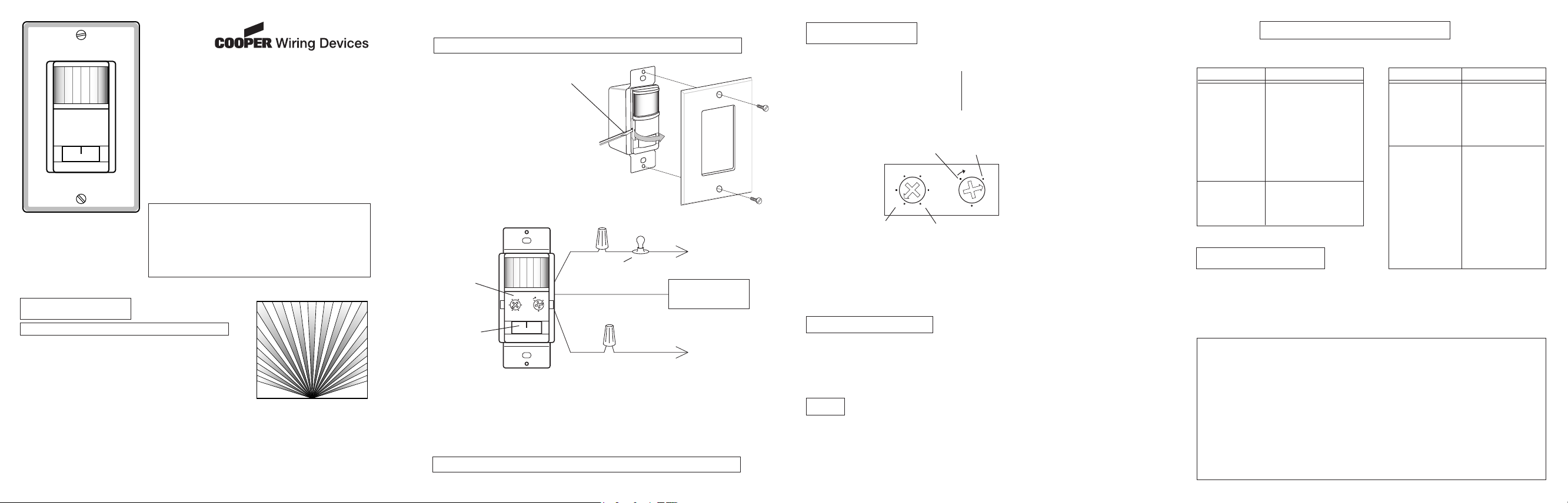
INSTALLING THE SWITCH
WARNING: Turn power off at the circuit breaker before wiring.
• Remove the decorative coverplate (secured by two
screws).
• Remove Control Cover. (Press in with screwdriver.
Swing out cover to remove.)
• Remove the existing switch (if this is a retrofit
application).
• Connect the detector as shown in the diagram.
Before installing the detector into the box, make
sure there is no wire exposed at the connection.
• Do not connect to neutral wire or damage to unit
will occur.
BLACK
Control Cover
Plate Removed
MODE
Selection
Switch
BLACK
TYPICAL INSTALLATION
• Mount the detector into the wall box with the mounting screws.
• For test pur poses, use a small screwdriver to turn the time control to TEST and the light control fully clockwise.
Turn the power back on at the circuit breaker.
• Set the switch to the AUTO mode. When unit stabilizes (about 1 minute) the sensor is ready to detect motion. If
motion is detected, the lights will turn on. The lights will turn off 5 seconds after motion is no longer detected.
Questions? Call 1-866-853-4293 8:00 AM to 7:00 PM Eastern Time, weekdays
LOAD
LIGHTING
LOAD
(NEUTRAL)
Green ground wire to
junction box screw or
grounding wire.
HOT
(LINE)
- 2 - - 3 - - 4 -
ADJUSTMENTS
TIME
There are 6 preset selections for the amount
of time the lights stay on: Test (5 seconds),
1, 5, 10, 15, and 20 minutes. Use a small,
phillips screw driver to adjust the TIME
control. Turn the TIME control until it “snaps”
into the desired time position.
Any Light
Level
5 Seconds
Note: Adjusting screws
found under (Off-Auto-On)
face plate.
20 Minutes
The senso r can be prevente d from turning on ligh ts
when there is already enough light in the r oom. Use
a small screw driver to set the light level using this
diagra m as a gui de. In t he fu lly clo ckwise posi tion , the senso r turns on lights even in full daylight.
In the f ull y count er- clo ckw ise poi tio n, the se nso r
Dark (low
light level)
on ly tu rn s on li ghts wh en the surro un di ng l igh t l ev el i s ve ry lo w.
When the light in the room is at the
•
level you want the lights to turn on,
set the switch to the AUTO position.
Put the TIME control to the 5 sec-
•
onds position.
Put the LIG HT control to the mini-
•
mum dark (fully counter-clockwise)
position. Wait for the lights to tur n
off.
Turn the LIGHT adjustment clock-
•
wise in very small steps and wait 2
seconds before moving your hand in
front of the sensor. Repeat until the
lights controlled by the sensor come
on. The light will now come on when
the light level is at or below the present level and motion is detected.
Complete Installation
Replace control panel cover and install the decorative wall plate. In installations where the Cooper motion
•
sensor switch is combined with other switches or outlets on an expanded box, a combination wall plate will
need to be purchased. Various combination wall plates are available at Home Centers and Electrical Supply
Stores.
Slide the switch a couple of times to make sure it operates freely.
•
USE
MODE Selection Switch
Moving the switch selects one of three modes of operation: OFF, AUTO, ON
OFF: Lights stay off.
AUTO: Lights come on for time set when motion is detected and the light level is below the set level.
ON: Lights stay on continuously.
LIGHT LEVEL
To adjust the photocell:
TROUBLESHOOTING
If you have a problem with your Wall Switch, first follow this guide. If the problem persists, call the
customer service hotline at 1-866-853-4293 between 8:00 AM and 7:00 PM ET weekdays.
SYMPTOM
Light does not come
on.
Lights do not stay
on in the Auto mode.
SPECIFICATIONS
Electrical input................................................................................................................................120V, 60 Hz
Fluorescent Load (Not for electronic ballasts)....................(2) 30 Watt minimum 400 Watt maximum Rapid Start
Motor Load.............................................................................................................................1/8 HP maximum
Incandescent..................................... ....................................................................................500W at 120V AC
On-Time..........................................................................................Adjustable approximately 5 sec. to 20 min.
Photocell Sensor.......................................................................................From dull daylight to less than 1 FC.
Coverage...............................................................................up to 15 ft. at 150°, up to 30 ft. in front of the sensor
YOUR COOPER WIRING DEVICES MOTION SENSOR TWO YEAR LIMITED WARRANTY
For a period of 2 years from the date of purchase, Cooper Wiring Devices will replace or repair the motion
sensing switch provided that it has not been subject to abuse, improper installation or improper use, and
is returned prepaid Cooper Wiring Devices Quality Control Depar tment at 203 Cooper Circle, Peachtree
City, GA, 30269. If the product has been discontinued, replacement will be made with the nearest available
equivalent model. This warranty does not cover consumables (such as fuses). Proof of purchase in the
form of a bill of sale or receipted invoice that shows that the item is within the applicable warranty period
must be presented to obtain the repair or replacement provided by the warranty. Repair or replacement as
provided under this warranty is the exclusive remedy of the customer. Cooper Wiring Devices shall not be
liable for any incidental or consequential damages for breach of any express or implied warranty on any
of its products. Except to the extent limited or prohibited by applicable law, any implied warranty of merchantability or fitness for a particular purpose on this product is limited in duration to the duration of this
warranty. Some states do not allow the exclusion or limitation of incidental or consequential damages, or
allow limitations on how long an implied warranty lasts, so the above limitations may not apply to you. This
warranty gives you specific legal rights and you may also have other rights which vary from state to state.
POSSIBLE CAUSE
1.
Circuit breaker or fuse is
turned off.
2.
If the lam p bein g co ntrolled has another switch,
it may be turned off.
3.
Bulb is defective.
4.
LIGH T control is set too
far toward the DARK posi-
5.
tion. MODE switch is set
to OFF instead of AUTO.
6.
Poor connection.
1.
Motion has stopped in the
room.
2.
TIME control is set for too
short a delay.
SYMPTOM
Light does not
turn off.
Light comes on for
no reason in the Auto
mode.
POSSIBLE CAUSE
Incorrect wiring.
1.
MODE switch is set to
2.
ON instead of AUTO.
Motion is still present.
3.
De lay set by TI ME
4.
c o nt ro l h a s n ot
expired.
Heating or cooling ob-
1.
je cts (s uch a s a ir
vents, appliances, or
drafts through the wall
box) are causing false
triggering.
Switch on the sensor
2.
has been turne d off
and back on.
There was a momen-
3.
tar y pow er int err uption. The light will turn
off automatically when
the “on” time expires.
598-1176-03 E
Page 2
TI ME LI GHT
+
Test 20
151
5 10
AUTO
OFF ON
6105
O
FF
O
N
AU
TO
T I M E L I G H T
+
Test 20
151
5 10
Interruptor de
Pared y Detector
de Movimiento
El inte rrup tor de pared y detect or de movimi ento 6105 dete cta
movimiento y prende la luz por un período de tiempo ajustable. Se
puede programar la fotocélula incorporada para que mantenga la luz
apagada cuando no se la necesita. La unidad goza de una excelente
sensibilidad y de un gran alcance de detección de 150°. Se la puede
usar con una luz incandescent e o c on una fluores cente que se
prenda rápido. (No use con balastro electrónico)
Su instalación es tan fácil como el cambiar un interruptor de pared.
Sin embargo, algunos códigos requieren que la instalación sea hecha
por un electricista calificado.
Sus características incluyen:
• Angulo de detección de movimiento de 150°.
• “On time” (duración) ajustable de 5 Seg. a 20 Minutos.
• Fotocélula ajustable.
• Funciona con luces incandescentes y fluorescentes de encendido
instantáneo. (Pero no con balastros electrónicos)
• Funciona con motores de hasta 1/8 hp (caballo de fuerza).
• Deslice el interruptor selector a la fase de OFF, ON y AUTO.
Se i ncluye: • interrup tor del det ector • Pla ca cu bert ora • 3 con ectores de alamb re • 2 tor nillo s gran des
• 2 tornillos pequeños.
INSTALACION
Atención: Para uso exclusivo en interiores.
ESCOJA UNA UBICACION
NUEVA APLICACION
Escoja una ubicación donde el detector de movimiento tenga una
vista clara de toda el área donde pueda haber movimiento de los
ocupantes.
APLICACION DE REEMPLAZO
El interruptor detector de movimiento reemplaza el interr uptor de
pare d exist ente. Uselo sólo donde la ubicaci ón del interruptor existente prop orci one una vista clar a del área ocupa da.
INFORMACION PARA APLICACIONES GENERALES
El detector es más sensitivo al movimiento que atraviesa el frente que al que se dirige hacia el detector.
El sensor detecta calor en movimiento y posiblemente las fuentes de calor que cambian rápidamente de temperatura. Por lo tanto, para evitar falsas alarmas, no coloque el detector frente a acondicionadores de aire,
calentadores u otras fuentes de calor o de frío.
30'
15'
0'
Vista de alcance de un plan típico
469MS-PT
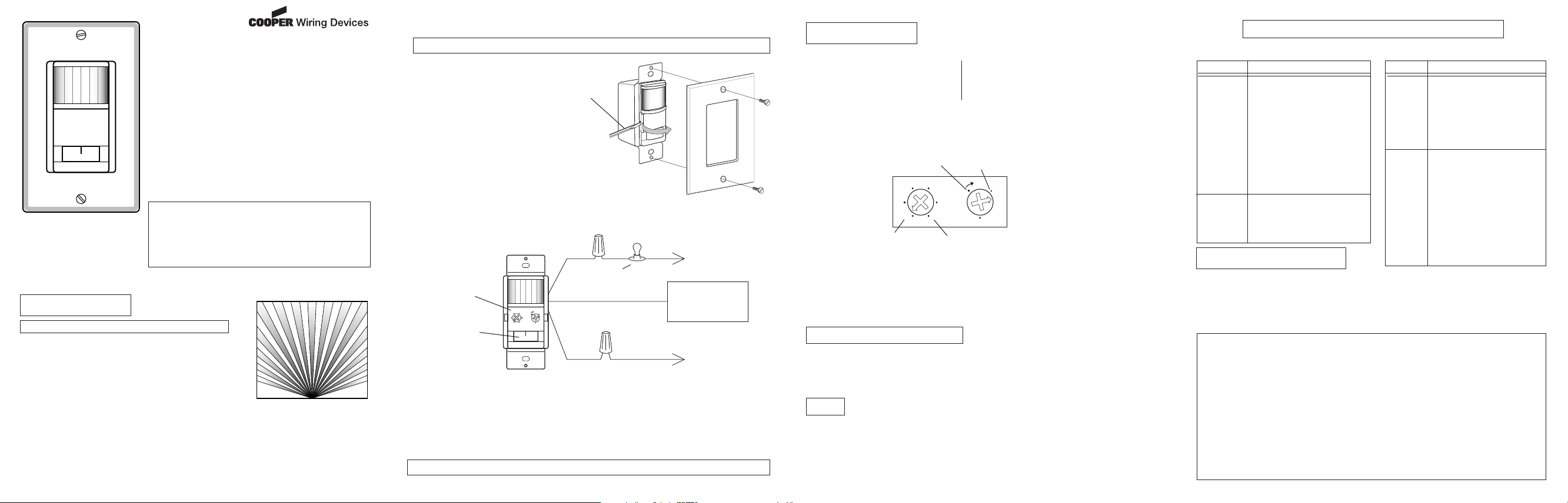
INSTALACION DEL INTERRUPTOR
ADVERTENCIA: Apague la energía en el cortacircuitos antes de hacer las conexiones.
• Quite la placa cubertora decorativa (asegurada con
dos tornillos decorativos).
• Para quitar la cublerta del control. (Presion e con
un destor nillador. Gire la tapa para quitarla.)
• Qui te el in te rru pt or ex is te nte ( es ta es u na
aplicación de reemplazo).
• Con ec te el de tec tor co mo se mu estra en el
diagrama. Antes de instalar el detector en la caja,
asegúrese que no haya alambre expuesto en la
conexión.
• No conecte al alambre neutro o la unidad se dañará.
NEGRO
Sin placa de la
tapa del control
Interruptor
selector de
fase
NEGRO
INSTALACION TIPICA
• Monte el detector en la caja de la pared con los tornillos de montaje.
•
Para realizar pruebas, use un destornillador pequeño para girar el control de tiempo a TEST y el control de
luz en sentido horario por completo. Prenda la energía en el cortacircuitos.
• Fije el interruptor en la fase de AUTO. Cuando la unidad se estabilice (cerca de 1 minuto) indicando que el
detector está listo para detectar movimiento. Si detecta movimiento, la luz se prenderá. La luz se apagará
5 segundos después de que ya no se detecte movimiento.
Preguntas? Llamar al 1-866-853-4293 8:00 AM a 7:00 PM Hora del Este, Dias Laborables
CARGA
CARGA
DE LUZ
(NEUTRO)
El alambre verde de
conexión a tierra al
tornillo de la caja de
empalmes o al alambre
de conexión a tierra.
VIVO
(LINEA)
- 2 - - 3 -
ADJUSTES
TIEMPO
Hay 6 ajustes precalibrados para el lapso de
tiempo que las luces permanecen encendidas:
Prueba (5 segundos), 1, 5, 10, 15 y 20 minutos. Use un destornillador Phillips pequeño
para regular el control de TIEMPO. Gire el
control hasta que se “coloque a presión” en la
posición de tiempo deseada.
Oscuro (nivel
de luz baja)
5 segundos
NOTE: Los tornillos de ajuste se encuentran (apaga-
Se pu ede evita r que el dete cto r pre nda las luc es
cuan do ya hay suficiente luz en el cuar to. Use un
pequeño destornillador para ajustar el nivel de luz de
acuerdo al diagrama que se muestra arriba. Cuando
se encuentra en la posició n completament e hacia la
derecha, el detector prende la luz aún el pleno día. Y
en la posició n comp letam ente hacia la izquie rda, el
dete ctor prende la luz cuand o el nivel de la luz del
alr eded or es muy baja. Se envia la unid ad con la
fotocélula en la posición de "Cualquier Nivel de Luz".
Cualquier
nivel de luz
•
•
20 minutos
•
•
•
do,-automatico,-prendido) debajo de la cubierta
frontal.
INSTALACION COMPLETA
Recoloque la tapa del panel de control e instale la placa ornamental de pared. En las instalaciones donde
•
se combine el interruptor detector de movimiento Cooper con otros interruptores o enchufes en una caja
extendida, se necesitará comprar una placa combinadora de pared. Varias placas combinadoras de pared
se pueden encontrar en los Centros Comerciales para el Hogar y en las Tiendas de Aparatos Eléctricos.
Declise el interruptor unas cuantas veces para asegurarse de que esté funcionando bien.
•
USO
Interruptor Selector de FASE
Mueva el interruptor para seleccionar una de las tres fases de operación: OFF, AUTO, ON
OFF: La luz permanece apagada.
AUTO: La luz se prende por el tiempo fijado cuando detecta movimiento y cuando el nivel de luz es más
bajo que el nivel fijado.
ON: La luz permanece prendida continuamente.
NIVEL DE LUZ
Para ajustar la fotocélula:
Cuando la luz del cuar to esté al
nivel al cual usted desea que la luz
se prenda, fije el interruptor en la
posición de AUTO.
Ponga el control de TIEMPO (TIME)
en la posición de 5 segundos.
Ponga el control de LUZ (LIGHT) en
su posición de mínimo nivel (completamente hacia la izquierda).
Espere que la luz se apague.
Gire el ajuste de la LUZ (LIGHT)
hac ia la der echa , con peq ueño s
gir os, y espe re po r 2 segundos
antes de mover su mano por frente
del detector. Rep ita hasta que la
luz controla da por el detect or se
prenda. La luz se prenderá cuando
el nivel de luz esté al nivel actual
o más abajo y c uando se detecte
movimiento.
Si tiene problemas con su interruptor de pared siga esta guía. Si el problema persiste, llamar a servicios del
GUIA DE SOLUCION DE PROBLEMAS
consumidor 1-866-853-4293 8:00 AM a 7:00 PM Hora del este, Dias Laborables.
SINTOMA
La luz no se
enciende.
La luz no se
queda
encendida
en la
fase de
Automático.
ESPECIFICACIONES
Entrada eléctric a......... .......... .......... .......... .................................................................................120V, 60 H z.
Carga Fluorescente (No use con balastro electrónico)...(2) 30 Vatios Min. y 400 Vatios Máx. de prendido rápido
Carga del motor....................... ..................................... ..................................... .....................1/8 HP maximó
Inca ndesc ente. ..... ..... ..... ..... .............. ..... ..... ..... ..... .............. ..... ..... ..... ..... ..... ......... ..... ..... ..... ..500 Vat ios
Duración...........................................................................Ajustable aproximadamente de 5 seg. a 20 minutos
Detector de fotocélula.............................................................................desde luz de pleno día a menos de 1FC.
Alcance................................................................................Hasta 15 pies a 150°, hasta 30 pies frente al detector
SU GARANTIA LIMITADA A DOS ANOS DE COOPER WIRING DEVICES PARA PRODUCTOS
Por un período de 2 años a partir de la fecha de compra, Cooper Wiring Devices reemplazará o reparará
el interruptor detector de movimiento siempre y cuando no haya sido objeto de abuso, instalación o uso
incorrectos, y sea remitido con porte pagado al Quality Control Department de Cooper’s, 203 Cooper Circle,
Peachtree City, GA 30269. Si el producto ha sido descontinuado, se reemplazará con el modelo disponible
de mayor similitud. Esta garantía no cubre artículos consumibles (tales como fusibles). Para obtener la reparación o reemplazo provitos en esta garantia, debe presentarse prueba de compra en la forma de un comprobante de venta o factura recibida que demuestre que el artículo se haya dentro del período aplicable de
garantía. La reparación o reemplazo provistos bajo esta garantía son el recurso exlusivo del cliente. Cooper
Wiring Devices no se hará responsable por cualquier daño incidental o consecuente a causa de violación de
cualquier garantía expresa o implícita de ninguno de sus productos. Excepto en casos donde sea limitado
o prohibido por leyes aplicables, cualquier garantía implícita de comerciabilidad o aptitud para un propósito
particular de este producto tiene su duración limitada a la duración de esta garantía. Algunos estados no
permiten la exclusión o limitación de daños incidentales o consecuentes, y no permiten limitaciones a la
duración de una garantía implícita, así que las limitaciones ya mencionadas podrían no aplicarse en su caso.
Esta garantía le da derechos legales específicos, y usted puede tener otros derechos los cuales varían de
acuerdo a los estados.
POSIBLE CAUSA
1.
El cortacircuitos o el fusible está
apagado.
2.
Si l a lám par a que se co ntr ola
tiene un interruptor, p uede estar
apagada.
3
La bombilla está mala.
4.
El contro l de LUZ (LIGHT) está
fijado muy cerca a la posición de
OBSCURIDAD (DARK)
5.
El selec to r de FAS E ( MODE)
está en APAGADO (OFF) y no en
AUTO(MATICO).
6.
Está cableado incorrectamente.
1.
El movimiento se ha parado en
el cuarto.
2.
El control de TIEMPO (TIME)
está programado para un retardo
muy corto.
SINTOMA
La luz no
se apaga.
La luz se
enciende
sin ninguna
razón en la
fase de
Automático.
ENSAMBLADOS
- 4 -
POSIBLE CAUSA
Está cableado incorrectamente.
1.
El sel ecto r de FASE (MODE)
2.
está en P RENDIDO (ON) y no
en AUTO(MATICO).
Todavía existe movimiento.
3.
El ret ardo pro gramado por el
4.
control de TIEMPO (TIME) todavia no se ha terminado.
Los objet os de calefac ció n o
1.
enfriamiento (conductos de aire,
electr odomést icos o corrien tes
de aire a t ravés de la caja de
la pared) están causando una
falsa alarma.
El interruptor de la lámpara ha
2.
sido apagado y prendido.
Hu bo u na i nter ru pc ió n de
3.
ene rgia mome ntán ea. La luz
se ap agar á automát ica mente
cuando se acabe el período de
"prendido" (on).
598-1176-03 S
 Loading...