

Page 1
Wireless Outdoor
ON DIP
1 2 3 4
ON DIP
1 2 3 4
Model 6022
Power Control
Features
• Add switched outlet convenience without rewiring.
• Tested and approved for outdoor use.
• Eight selectable channels available, so multiple switches can be used in the
same home.
• Allows remote or dusk-to-dawn operation.
• Car visor clip included for convenience.
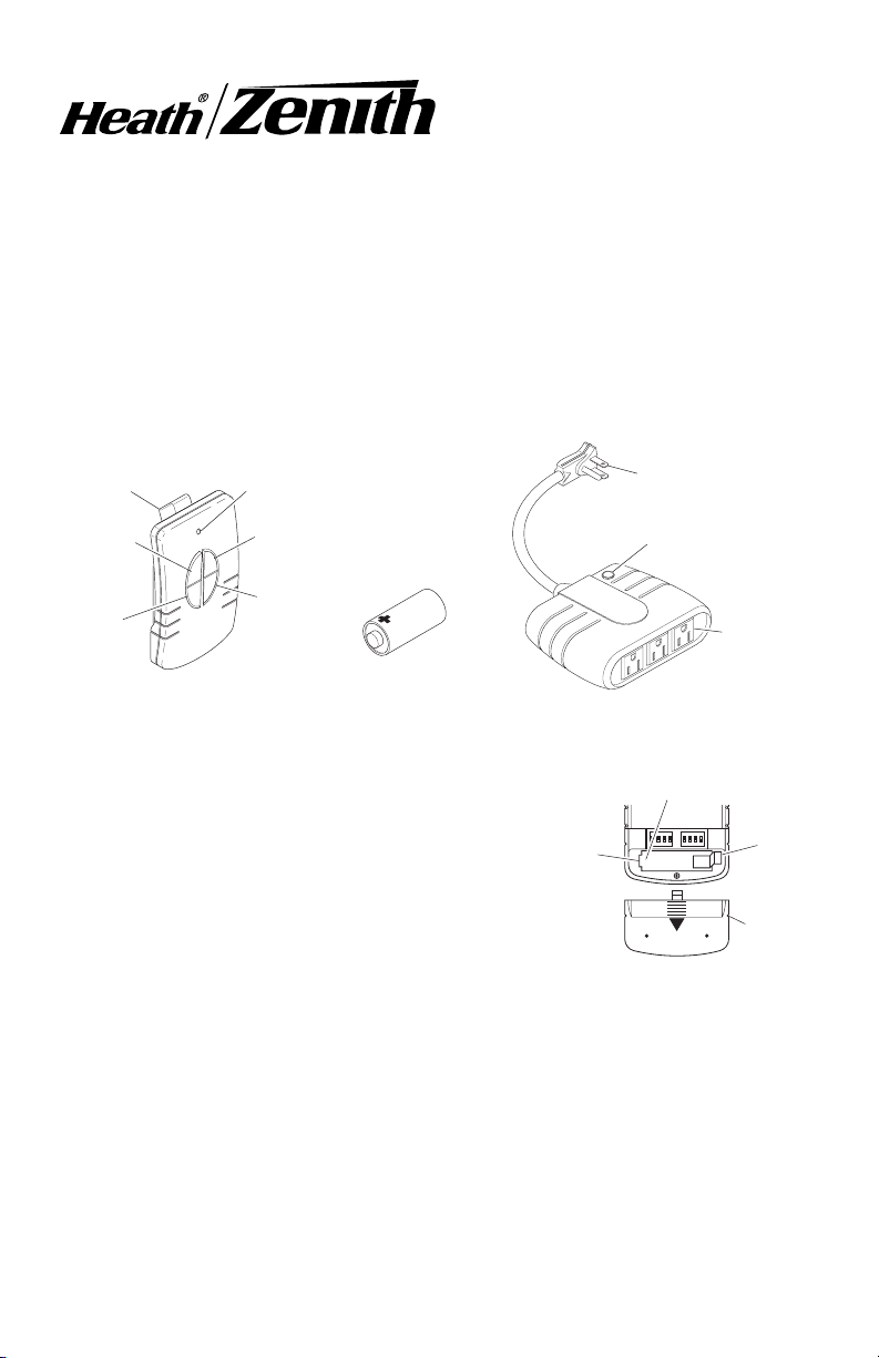
Car Visor
Clip
Manual
Switch
Auto
Switch
Remote Control
LED Indicator Light
ON Switch
OFF Switch
12-Volt (A23 Type)
Battery (Included)
Outdoor Module
Operation
Eight selectable channels allow the user to
operate several systems at different locations in your home. If purchasing more than
one wireless control system, select different
operating channels for each system or they
will interact with each other.
1. Remove Tab from Battery Chamber.
Remove cover from back of transmitter
by pressing on it with your thumb and
sliding it off as shown in Figure 1. Gently pull tab out of battery chamber.
Slide cover onto transmitter.
2. Plug in Outdoor Module. Remember, the outdoor module requires a grounded
outlet. If you do not have a grounded outlet, you should contact an electrician
to upgrade your electrical system for your safety. See precautions before
using module (see page 2).
3. Mount Outdoor Module. Hang module with two nails or screws. There are
two keyholes on the back for this purpose (see Figure 2, page 2). DO NOT
allow module to hang by cord.
Battery
Chamber
(Type A23)
Grounded Plug
Light Sensor
Cover
Device
Receptacles
Positive Terminal
Figure 1
Tab
Battery
Cover
© 2007 HeathCo LLC 598-1108-05
Page 2
4. Plug in devices you wish to control.
Caution: Do not exceed the maximum load limits listed in Specications
section (see page 4).
5. Check operation. Place hand over light sensor cover. The unit should switch
on. To check remote operation, toggle left switch to manual. Toggle ON/OFF
switch.
6. Remote Control Functions.
Automatic Mode: Toggle left switch to automatic to allow switched devices
to come on at dusk and turn off at dawn. This is the default mode when rst
powered up or after power outage.
Manual Mode: Toggle left switch to manual to allow operator to manually
switch devices on and off. Use right toggle to switch devices on and off.
Note: LED will light when toggle switches
are pushed.
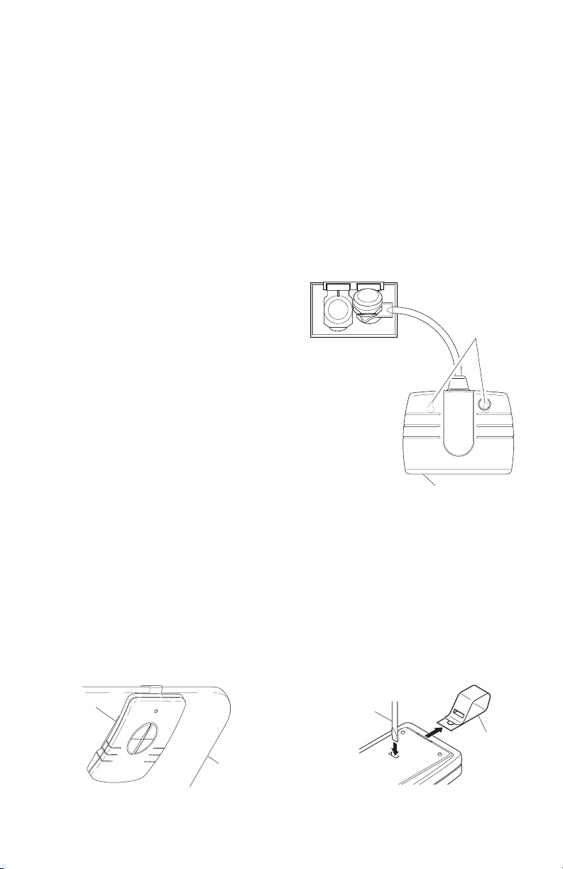
Precautions When Using
Keyholes to
Hang Unit
Outdoor Module
• The module must be oriented with the
power outlet down to prevent rain from entering the
unit (see Figure 2).
• The module must be located below the wall outlet as
shown. This is to prevent rain from running down the
cord into the wall outlet.
• Note: The National Electrical Code and Canadian
Electrical Code (and most local codes) require that
outside outlets be protected by a Ground Fault Interrupter (GFI).
Power Outlets
Figure 2
Car Visor Clip
The remote control is equipped with a removable car visor clip for added con-
venience. The car visor clip may be removed to allow the remote to lie at on
table tops or other horizontal surfaces.
1. Attach car visor clip to car visor as shown in Figure 3.
2. To remove car visor clip. Insert a small at-head screw driver into slot on
back of remote. Gently push portion of clip inside of remote with screwdriver
while pulling clip out of remote from top (see Figure 4).
Remote
Control
Screwdriver
Visor Clip
Car Visor
Figure 3 Figure 4
2 598-1108-05
Page 3
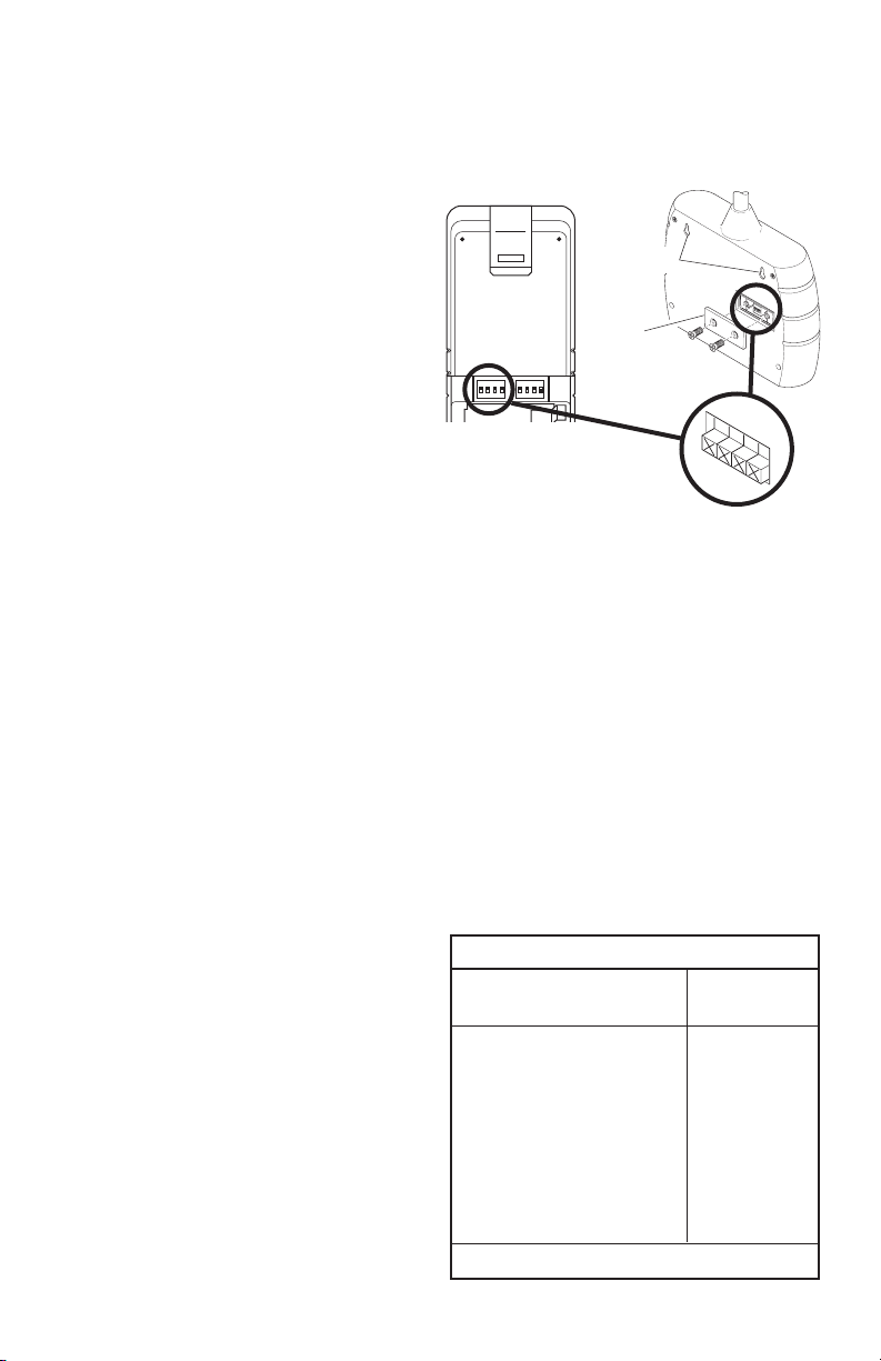
Channel Settings
O
N
1
2
3
4
ON DIP
1 2 3 4
ON DIP
1 2 3 4
ON
1 2 3
4
Note: Most installations will not require you to change any of the dip
switches on your plug-in module or remote control.
The remote control and outdoor
module communicate by using channels that can be changed by sliding
dip switches into the ON or OFF [on
some switches the numbers 1 (ON)
and/or 0 (OFF) are used] position on
both the remote control and outdoor
module. The channel is factory set;
however, there are 3 switches (8
selectable channels) that allow you
to expand your system and prevent
outside interference. Other wireless
products may cause interference and
the system may not function properly.
Dip Switches - Shown
in the OFF Position
(Factory Default)
Follow the instructions below for setting a new channel.
1. Open the cases and locate dip switches on both the remote control and
outdoor module (see Figure 5).
2. The remote control and outdoor module both have two positions (ON and
OFF) on each of the four dip switches. Dip switches 1 through 3 are used
for setting the channel. Use the table below to set channel 2 after setting
channel 1. Note: The channels must be programmed according to the table
below for all 4 functions of the remote control to work properly. The receiver(s)
must match the code settings for channel 1. Use the table below to set the
corresponding code for channel 2.
3. To change the channel, slide dip switches to ON or OFF as needed. It is
recommended to only change one dip switch at a time and then check to see
if the system is functioning properly. Note: Dip switches in positions 1 through
3 must be in the exact same
conguration on both the remote
control and outdoor module for
this system to function properly.
Channel Setting Codes
Channel 1 Transmitter Channel 2
and Receiver(s) Transmitter
0000 0001
0010 0011
0100 0101
0110 0111
1000 1001
1010 1011
1100 1101
1110 1111
0 = OFF 1 = ON
3598-1108-05
Keyholes
Access
Door
Figure 5
Page 4

Troubleshooting Guide
SYMPTOM
Device does
not come on.
Device does
not turn off.
Device comes
on randomly.
POSSIBLE CAUSE
1. Circuit breaker or fuse is turned off.
2. Switch on device is turned off.
3. Device is defective. Try remote using different device.
4. Signals from transmitter are being blocked, or transmitter
is out of range. Check for metal objects that could block
the signal, or reposition the transmitter.
5. Weak battery in the transmitter.
6. Dip switches on remote and outdoor module do not
match.
7. Remote set to automatic (Dusk to Dawn) and surrounding
light level is too bright.
1. Same as 4 & 5 above.
2. Remote set to automatic (Dusk to Dawn) and surrounding
light level is too dark.
1. Short term power line failure.
2. Another transmitter on the same channel.
Technical Service
Please call 1-800-858-8501 (English speaking only) for assistance before returning
product to store.
If you experience a problem, follow this guide. You may also want to visit our
Web site at: www.hzsupport.com. If the problem persists, call* for assistance
at 1-800-858-8501 (English speaking only), 7:30 AM to 4:30 PM CST (M-F).
You may also write* to:
HeathCo LLC
P.O. Box 90004, Bowling Green, KY 42102-9004
ATTN: Technical Service
* If contacting Technical Service, please have the following information available:
Model Number, Date of Purchase, and Place of Purchase.
No Service Parts Available for this Product
Regulatory Information
This device complies with Part 15 of the FCC Rules and RSS-210 of Industry
Canada. Operation is subject to the following two conditions: (1) this device may
not cause harmful interference, and (2) this device must accept any interference
received, including interference that may cause undesired operation.
The user is cautioned that changes or modications not expressly approved by
the party responsible for regulatory compliance could void the user’s authority
to operate the equipment.
WARNING: This product contains chemicals known to the State of California
to cause cancer or birth defects, or other reproductive harm.
4 598-1108-05
Page 5

Specications
Range ...........................................................................Up to 100 feet (30.5 m)
Maximum Load ......................................................................13 amps resistive
960 Watts incandescent
960 Watts uorescent
1/3 H.P. motor
Rated Voltage ..........................................................................120 VAC, 60 Hz
Battery .....................................................................12-volt alkaline (A23 type)
TWO YEAR LIMITED WARRANTY
This is a “Limited Warranty” which gives you specic legal rights. You may also
have other rights which vary from state to state or province to province.
For a period of two years from the date of purchase, any malfunction
caused by factory defective parts or workmanship will be corrected at no
charge to you.
Not Covered - Repair service, adjustment and calibration due to misuse,
abuse or negligence, light bulbs, batteries, and other expendable items are
not covered by this warranty. Unauthorized service or modication of the
product or of any furnished component will void this warranty in its entirety.
This warranty does not include reimbursement for inconvenience, installation,
setup time, loss of use, unauthorized service, or return shipping charges.
This warranty covers only HeathCo LLC assembled products and is not
extended to other equipment and components that a customer uses in
conjunction with our products.
THIS WARRANTY IS EXPRESSLY IN LIEU OF ALL OTHER WARRANTIES, EXPRESS OR IMPLIED, INCLUDING ANY WARRANTY, REPRESENTATION OR CONDITION OF MERCHANT ABILITY OR THAT THE
PRODUCTS ARE FIT FOR ANY PARTICULAR PURPOSE OR USE, AND
SPECIFICALLY IN LIEU OF ALL SPECIAL, INDIRECT, INCIDENTAL, OR
CONSEQUENTIAL DAMAGES.
REPAIR OR REPLACEMENT SHALL BE THE SOLE REMEDY OF THE
CUSTOMER AND THERE SHALL BE NO LIABILITY ON THE PART
OF HEATHCO LLC FOR ANY SPECIAL, INDIRECT, INCIDENTAL, OR
CONSEQUENTIAL DAMAGES, INCLUDING BUT NOT LIMITED TO ANY
LOSS OF BUSINESS OR PROFITS, WHETHER OR NOT FORESEEABLE. Some states or provinces do not allow the exclusion or limitation of
incidental or consequential damages, so the above limitation or exclusion
may not apply to you. Please keep your dated sales receipt, it is required
for all warranty requests.
HeathCo LLC reserves the right to discontinue products and to change specications at any time without incurring any obligation to incorporate new features
in products previously sold.
5598-1108-05
Page 6
Control de
ON DIP
1 2 3 4
ON DIP
1 2 3 4
encendido exterior
Modelo 6022
inalámbrico
Características
• Añade la conveniencia de un tomacorriente controlado con interruptor sin
volver a cablear.
• Probado y aprobado para uso externo.
• Ocho canales disponibles a elección, de manera que interruptores múltiples
pueden ser usados en la misma casa.
• Permite una operación remota o una de “crepúsculo al amanecer”.
• Presilla de la visera del carro incluida por conveniencia.
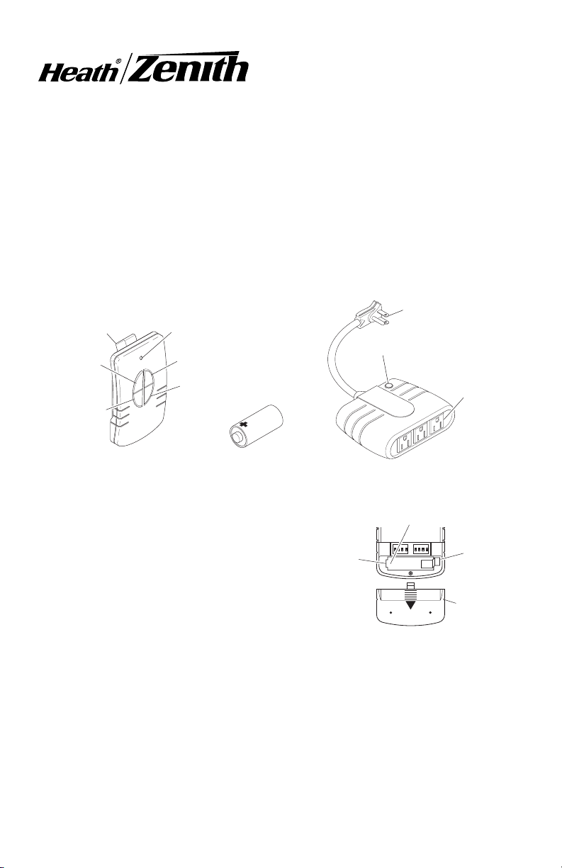
Presilla de la
visera del carro
Interruptor
manual
Interruptor
automático
Control remoto
Luz indicadora LED
Interruptor ON
Interruptor
OFF
Batería de 12 voltios
(tipo A23) (Incluida)
Tapa del detector de luz
Módulo exterior
Clavija de conexión
a tierra
Tomacorrientes
del dispositivo
Operación
Los ocho canales selectores
permiten al usuario operar varios
sistemas en diferentes lugares
de su casa, si compra más de un
sistema de control inalámbrico,
Compartimento
de la batería
(tipo A23)
seleccione los diferentes canales
de operación para cada sistema.
En caso contrario éstos interactuarán entre ellos.
1. Retire la aleta del compartimento de la batería. Retire la tapa posterior del
transmisor presionándola con su pulgar y deslizándola hacia fuera como se
muestra en la Figura 1. Hale la aleta con suavidad fuera del compartimento
de la batería. Deslice la tapa en el transmisor.
2. Enchufe el módulo exterior. Recuerde, el módulo exterior requiere un
tomacorriente con conexión a tierra. Si no tiene una clavija con conexión a
tierra debería, para su seguridad, ponerse en contacto con un electricista
y actualizar su sistema eléctrico. Vea las precauciones antes de usar el
módulo (Vea la página 7).
© 2007 HeathCo LLC 598-1108-05 S
6 598-1108-05
Terminal Positivo
Aleta
Tapa de la
batería
Figura 1
Page 7

3. Instale en el módulo exterior. Fije el módulo usando dos clavos o tornillos.
Hay dos agujeros para este propósito en la parte posterior (Vea la Figura
2). NO je el módulo usando una cuerda.
4. Enchufe los dispositivos que usted desee controlar.
Precaución: No exceda los límites máximos de carga indicados en la sec-
ción especicaciones (Vea la página 10).
5. Revise la operación. Coloque la mano sobre la tapa del detector de luz.
La unidad debería encenderse. Para revisar la operación remota, conmute
el interruptor de la izquierda a manual. Conmute el interruptor ON/OFF.
6. Funciones del control remoto.
Modo automático: Conmute el interruptor de la izquierda a automático para
permitir que los dispositivos controlados con interruptor se enciendan en el
crepúsculo y se apaguen al amanecer. Este es el modo ajustado en fábrica
cuando por primera vez es energizado o luego de un corte de energía.
Modo manual: Conmute el interruptor de la izquierda a manual para permitir
que el operador encienda o apague manualmente los dispositivos. Realice
la conmutación correcta para encender o apagar los dispositivos.
Nota: El LED se iluminará cuando los in-
terruptores de palanca estén pulsados.
Oricios para
jar la unidad
Precauciones cuando use el
módulo exterior
• El módulo debe estar orientado con
el tomacorriente hacia abajo para evitar que la lluvia
ingrese en la unidad (Vea la Figura 2).
• El módulo debe estar ubicado abajo del tomacorriente de
pared, como se muestra. Esto es para evitar que la lluvia
baje por el cordón hacia el tomacorriente de pared.
• Nota: el código eléctrico nacional y el código eléctrico
canadiense (y la mayoría de los códigos locales) exigen
que los tomacorrientes exteriores estén protegidos con
un interruptor de falla a tierra (GFI).
Tomacorrientes
Figura 2
Presilla de la visera del carro
Para mayor conveniencia el control remoto está equipado con una presilla de la
visera del carro que puede retirarse para permitir que el control remoto quede
horizontal sobre la parte superior de la mesa u otras supercies horizontales.
1. Junte la presilla de la visera del carro a la visera del carro según se
muestra en la Figura 3, página 8.
2. Para retirar la presilla de la visera. Inserte un destornillador pequeño cabe-
za plana en la ranura posterior del control remoto. Empuje con cuidado la
porción de la presilla que está hacia adentro del control con el destornillador
mientras hala la presilla hacia fuera del control desde arriba (Vea la Figura
4, página 8).
7598-1108-05
Page 8

Control
O
N
1
2
3
4
ON DIP
1 2 3 4
ON DIP
1 2 3 4
ON
1 2 3
4
Destornillador
remoto
Presilla de
la visera
Visera del
carro
Figura 3 Figura 4
Ajustes del canal
Nota: la mayoría de instalaciones no requerirán que usted cambie ninguno
de los interruptores de circuito impreso en su módulo enchufable o en
el control remoto.
El control remoto y el módulo exterior se comunican mediante canales que
pueden ser cambiados accionando los interruptores de circuito impreso a la
posición ON u OFF tanto en el control remoto como en el módulo exterior [en
algunos interruptores se usan los números 1 (ON) y/o 0 (OFF)]. El canal viene
ajustado de fábrica; sin embargo, hay tres interruptores (8 canales a elegir) que
le permiten expandir su sistema y evitar interferencia exterior. Otros productos
inalámbricos pueden ocasionar interferencia y el sistema puede que no funcione
apropiadamente. Siga las instrucciones que siguen para jar un nuevo canal.
1. Abra los compartimentos y ubique los interruptores de circuito impreso tanto
en el control remoto como en el módulo exterior (Vea la Figura 5).
Oricios
Puerta de
acceso
Interruptores de circuito
impreso- Mostrados en la po-
sición OFF (Ajuste de fábrica).
Figura 5
8 598-1108-05
Page 9

2. Cada uno de los cuatro interruptores de circuito impreso del control remoto
y del módulo exterior tiene dos posiciones (ON y OFF). Los interruptores
de circuito impreso del 1 al 3 se usan para calibrar el canal. Use la tabla de
abajo para calibrar el canal 2 después de hacerlo con el canal 1. Nota: Los
canales deben programarse según la tabla de abajo para que todas las 4
funciones del control remoto funcionen correctamente. Para el canal 1 las
calibraciones de código del(los) receptor(es) deben emparejar. Use la tabla
de abajo para calibrar el código correspondiente para el canal 2.
3. Para cambiar el canal, mueva los interruptores de circuito impreso a las
posiciones ON u OFF según se necesite. Es recomendable cambiar solamente un interruptor de circuito impreso a la vez y luego revisar y ver si
el sistema funciona apropiadamente. Nota: Para que el sistema funcione
apropiadamente los interruptores de circuito impreso de las posiciones 1
a la 3 deben tener exactamente la misma conguración tanto en el control
remoto como en el módulo exterior.
Códigos de calibración del canal
Canal 1 transmisor Canal 2
y receptor(es) transmisor
0000 0001
0010 0011
0100 0101
0110 0111
1000 1001
1010 1011
1100 1101
1110 1111
0 = ENCENDIDO 1 = APAGADO
9598-1108-05
Page 10

Guía De Análisis De Averías
SINTOMA
El dispositivo
no se enciende.
El dispositivo
no se apaga.
El dispositivo
se enciende al
azar.
POSIBLE CAUSA
1. El disyuntor o el fusible está desconectado.
2. El interruptor del dispositivo está apagado.
3. El dispositivo está defectuoso. Pruebe el control remoto
usando un dispositivo diferente.
4. Las señales del control remoto están bloqueadas, o el control
remoto está fuera de alcance. Vea si hay objetos de metal que
puedan bloquear la señal, o reubique el control remoto.
5. Pila débil en el control remoto.
6. Los interruptores de circuito impreso en el control remoto
y el módulo exterior no emparejan.
7. El control remoto está puesto en automático (crepúsculo
al amanecer) y el nivel de iluminación circundante es
demasiado brillante.
1. Igual que los números 4 y 5 de arriba.
2. El control remoto está puesto en automático (crepúsculo
al amanecer) y el nivel de iluminación circundante es
demasiado oscuro.
1. Desconexión momentánea de la línea de alimentación.
2. Otro control remoto en el mismo canal.
Servicio Técnico
Favor de llamar al 1-800-858-8501 (sólo para hablar en inglés) para pedir ayuda
antes de devolver el producto a la tienda.
Si tiene algún problema, siga esta guía. Usted puede también visitar nuestro sitio
Web: www.hzsupport.com. Si el problema continúa, llame al 1-800-858-8501
(sólo para hablar en inglés), de 7:30 AM a 4:30 PM CST (L-V). Usted puede
también escribir a:
HeathCo LLC, P.O. Box 90004, Bowling Green, KY 42102-9004
ATTN: Technical Service (Servicio Técnico)
* Si se llama al Servicio Técnico, por favor tener lista la siguiente información:
Número de Modelo, Fecha de compra y Lugar de compra.
No hay piezas de servicio disponibles para este producto.
Información Regulatoria
Este aparato cumple con la Parte 15 de las Reglas de la FCC (Comisión Federal de
Comunicaciones) y con la RSS-210 de las Industrias del Canadá. El funcionamiento
está sujeto a las dos siguientes condiciones: (1) este aparato no puede causar interferencias dañinas, y (2) este aparato debe aceptar cualquier interferencia recibida,
incluyendo una interferencia que pueda causar un funcionamiento indeseable.
Se advierte al usuario que cambios o modicaciones no aprobadas expresamente por la parte responsable de cumplir con los reglamentos podría invalidar
la autoridad del usuario para el uso de este equipo.
10 598-1108-05
Page 11

Especicaciones
Alcance ........................................................................................ Hasta 30,5 m
Carga Máxima ...............................................................13 amperios resistivos
960 Vatios incandescente
960 Vatios uorescente
Motor de 1/3 H.P.
Tensión Nominal ......................................................................120 VCA, 60 Hz
Pila.................................................................. Alcalina de 12 voltios (tipo A23)
ADVERTENCIA: Este producto contiene substancias químicas conocidas en
el estado de California como causas de cáncer o de defectos al recién nacido
o de otros daños de reproducción.
GARANTÍA LIMITADA A 2 AÑOS
Esta es una “Garantía Limitada” que le da a Ud. derechos legales especícos.
Usted puede también tener otros derechos que varían de estado a estado o de
provincia a provincia.
Por un período de 2 años desde la fecha de compra, cualquier mal funcionamiento
ocasionado por partes defectuosas de fábrica o mano de obra será corregido sin
cargo para Ud.
No cubierto - Servicio de reparación, ajuste y calibración debido al mal uso, abuso o
negligencia, bombillas, baterías, u otras partes fungibles no están cubiertas por esta
garantía. Los Servicios no autorizados o modicaciones del producto o de cualquier
componente que se provee invalidarán esta garantía en su totalidad. Esta garantía
no incluye reembolso por inconveniencia, instalación, tiempo de instalación, perdida
de uso, servicio no autorizado, o costos de transporte de retorno.
Esta garantía cubre solamente los productos ensamblados por HeathCo LLC y
no se extiende a otros equipos o componentes que el consumidor usa junto con
nuestros productos.
ESTA GARANTÍA ESTÁ EXPRESAMENTE EN LUGAR DE OTRAS GARANTÍAS,
EXPRESADAS O SOBREENTENDIDAS, INCLUYENDO CUALQUIER GARANTÍA,
REPRESENTACIÓN O CONDICIÓN DE COMERCIABILIDAD O QUE LOS PRODUCTOS SE ADAPTEN PARA CUALQUIER PROPÓSITO O USO EN PARTICULAR, Y ESPECIFICAMENTE EN LUGAR DE TODOS LOS DAÑOS ESPECIALES,
INDIRECTOS, INCIDENTALES Y CONSECUENTES.
LA REPARACIÓN O EL REEMPLAZO DEBERÍA SER LA ÚNICA SOLUCIÓN DEL
CLIENTE Y NO HABRÁ RESPONSABILIDAD POR PARTE DE HEATHCO LLC POR
CUALQUIER DAÑO ESPECIAL, INDIRECTO, INCIDENTAL O CONSECUENTE,
INCLUIDOS PERO NO LIMITADOS A CUALQUIER PÉRDIDA DE NEGOCIO O
GANACIAS SEAN O NO PREVISIBLES. Algunos estados o provincias no permiten
la exclusión o limitación de daños incidentales o consecuentes, de modo que la
limitación o exclusión arriba indicada puede que no se aplique a Ud. Por favor guarde
su recibo de venta fechado; se lo requiere para cualquier solicitud de garantía.
HeathCo LLC se reserva el derecho de descontinuar productos y de cambiar
especicaciones, cuando desee, sin incurrir en ninguna obligación de incorporar
las nuevas características en los productos vendidos anteriormente.
11598-1108-05
Page 12

Commande
ON DIP
1 2 3 4
ON DIP
1 2 3 4
d'alimentation
Modèle 6022
Caractéristiques
• Obtenez la commodité d'une prise à interrupteur sans devoir recâbler.
• Testée et approuvée pour utilisation à l'extérieur.
• Huit canaux optionnels disponibles, vous permettant d'utiliser de multiples
interrupteurs dans une même maison.
• Choix de fonctionnements à distance et crépusculaire.
Bride d'attache de visière pare-soleil d'auto comprise, pour plus de commodité.
•
extérieure sans l
Bride d'attache de visière
pare-soleil d'auto
Commutation
manuelle
Commutation
automatique
Télécommande Module extérieur
Voyant à DÉL
Interrupteur de
marche (ON)
Interrupteur
d'arrêt (OFF)
Pile de 12 V (type
A23) (comprise)
Prise avec
mise à la terre
Verre du capteur
de lumière
Prises de courant
d'appareils
Fonctionnement
Huit (8) canaux optionnels permettent
à l'utilisateur de faire fonctionner plusieurs systèmes en divers emplacements de son domicile. Si vous vous
procurez plus qu'un seul système de
Compartiment
des piles
(Type A23)
commande sans l, prenez soin de
sélectionner des canaux actifs différents pour chaque système, sinon ils
interagiront les uns avec les autres.
1. Enlevez la languette du compartiment des piles. Ôtez le couvercle du dos
de l'émetteur en appuyant dessus à l'aide du pouce et en le faisant glisser au
dehors, comme le montre la Figure 1. Tirez doucement la languette hors du
compartiment des piles. Glissez le couvercle sur le transmetteur.
Borne positive
Languette
Couvercle
des piles
Figure 1
© 2007 HeathCo LLC 598-1108-05 F
12 598-1108-05
Page 13

2. Branchez le module extérieur. N'oubliez pas que le module extérieur
nécessite une prise de courant avec mise à la terre. Si vous n'en possédez
pas une, communiquez avec un électricien an qu'il améliore votre système
électrique pour votre sécurité. Voir les mesures de précaution préalables à
l'utilisation du module.
3. Montez le module extérieur. Accrochez le module, à l'aide de deux (2)
clous ou vis. On trouve deux orices de type « trou de serrure » au dos du
module, qui permettent de l'accrocher (voir Figure 2). NE laissez PAS le
module pendre par son câble !
4. Branchez l'appareil que vous désirez commander.
Mise en garde : Ne dépassez pas les charges maximales indiquées dans
la section Spécications (voir p. 15).
5. Vériez le fonctionnement. Placez votre main par-dessus le verre du
capteur de lumière. L'appareil devrait alors s'allumer. Pour vérier le fonctionnement de la télécommande, basculez le commutateur de gauche sur
la position manuelle (MANUAL). Faites alterner la position de l'interrupteur
de marche-arrêt (ON/OFF) à bascule.
6. Fonctions de la télécommande.
Mode automatique : Basculez l'interrupteur de gauche sur la position auto-
matique pour que l'appareil branché puisse s'allumer au coucher du soleil et
s'éteindre au lever. Il s'agit du mode par défaut lorsque le système est mis
sous tension initialement, ou suite à une coupure de courant.
Mode manuel : Basculez l'interrupteur de gauche sur la position manuelle
(MANUAL) pour pouvoir commander manuellement la mise en circuit/hors
circuit de l'appareil branché su système. Utilisez l'interrupteur à bascule de
droite pour commander la mise en circuit/hors circuit de l'appareil.
Remarque : La DÉL s'allume lorsque les interrupteurs à bascule sont actionnés.
Mesures de précaution pour l'utilisation du module
extérieur
• Le module doit être orienté de telle sorte
que la prise de courant soit dirigée vers
le bas, an que la pluie ne pénètre pas
dans l'unité (voir Figure 2).
• Le module doit être installé en dessous de la prise de courant murale, comme c'est
montré. Ainsi, l'eau de pluie ne ruissellera pas le
long du cordon jusque dans la prise murale.
• Remarque : Le Code national de l'électricité (ÉtatsUnis) et le Code canadien de l'électricité (ainsi que la
plupart des codes locaux) prescrivent que les prises
de courant extérieures doivent être protégées par
un disjoncteur de fuite à la terre.
13598-1108-05
Orices de type « trou
de serrure », pour
accrocher l'unité
Prises de courant
des appareils
Figure 2
Page 14

Bride d'attache pour visière pare-soleil d'auto
O
N
1
2
3
4
ON DIP
1 2 3 4
ON DIP
1 2 3 4
ON
1 2 3
4
La télécommande est munie d'une bride d'attache amovible pour visière pare-soleil
d'auto, qui ajoute à la commodité. On peut ôter cette bride d'attache pour poser
la télécommande à plat sur un dessus de table ou autre surface horizontale.
1. Fixez la bride d'attache pour visière pare-soleil d'auto, comme le montre
la Figure 3.
2. Pour ôter la bride d'attache. Insérez la pointe d'un petit tournevis à lame plate
dans la fente de l'arrière de la télécommande. Avec la pointe du tournevis,
enfoncez délicatement la partie de la bride d'attache qui est à l'intérieur de
la fente tout en tirant sur la bride par le haut de l'unité (voir Figure 4).
Télécommande
Tournevis
Visière pare-
soleil d'auto
Figure 3 Figure 4
Réglages des canaux
Remarque : Avec la plupart des installations, vous n'aurez à changer la
position d'aucun des commutateurs DIP de votre module enchable ou
de votre télécommande.
La télécommande et le module
extérieur communiquent l'une
avec l'autre en utilisant des
canaux, que l'on peut changer
en faisant glisser des commutateurs DIP en position en circuit
(ON) ou hors circuit (OFF)
[certains de ces commutateurs
utilisent les chiffres « 1 » et «
0 », respectivement, pour les
positions ON et OFF] sur la
télécommande et sur le module
extérieur. Le canal est déjà réglé à l'usine; toutefois, trois (3)
Commutateurs DIP - montrés en position hors circuit
(OFF) (position par défaut,
préréglée en usine)
commutateurs (huit [8] canaux
optionnels) vous permettent
de développer votre système et de prévenir les brouillages externes. En effet,
d'autres produits de type à commande sans l peuvent créer des brouillages,
et le système peut ainsi ne pas fonctionner correctement. Suivez les directives
ci-dessous pour régler un nouveau canal.
1. Ouvrez les compartiments, et repérez les commutateurs DIP de la télécommande et du module extérieur (voir Figure 5).
14 598-1108-05
Orices de type
« trou de serrure »
Couvercle
d'accès
Figure 5
Bride d'at-
tache
Page 15

2. Chacun des quatre commutateurs DIP de la commande et du module extérieur présente deux (2) positions (en circuit [ON] et hors circuit [OFF]).Les
commutateurs DIP 1 à 3 servent à sélectionner le canal. Servez-vous du
tableau ci-dessous pour régler le canal 2, après avoir réglé le canal 1. Note :
Pour que les 4 fonctions de la télécommande agissent correctement, les
canaux doivent être programmés conformément aux données du tableau ci-
dessous. Les récepteurs doivent être congurés de façon identique au canal
1. Consultez le tableau ci-dessous pour programmer le code correspondant
au canal 2.
3. Pour changer de canal, faites glisser les commutateurs DIP sur la position
en circuit (ON) ou hors circuit (OFF), au besoin. Il est recommandé de ne
changer qu'un commutateur DIP à la fois, puis de vérier si le système
fonctionne correctement. Remarque : Les commutateurs DIP 1 à 3 de la
télécommande doivent avoir exactement la même conguration que ceux
du module extérieur pour que ce système puisse bien fonctionner.
Codes de programmation des canaux
Canal 1 du transmetteur Canal 2 du
et des récepteurs transmetteur
0000 0001
0010 0011
0100 0101
0110 0111
1000 1001
1010 1011
1100 1101
1110 1111
0 = OFF 1 = ON
15598-1108-05
Page 16

Guide De Dépannage
SYMPTÔME
L'appareil branché ne s'allume
pas.
L'appareil branché ne s'éteint
pas.
L'appareil s'al-
lume de façon
intermittente.
CAUSE POSSIBLE
1. Le disjoncteur est coupé, ou le fusible est grillé.
2. L'interrupteur de marche-arrêt de l'appareil branché est
en position d'arrêt.
3. L'appareil branché est défectueux. Essayez votre télécommande sur un autre appareil.
4. Les signaux de l'émetteur sont bloqués ou l'émetteur
n'est pas assez puissant. Vérier la présence d'objets
métalliques susceptibles de bloquer le signal, ou déplacer
l'émetteur.
5. La pile de l'émetteur est faible.
6. Les positions des commutateurs DIP de la télécommande
ne correspondent pas à celles des commutateurs DIP du
module extérieur.
7. La télécommande est réglée sur la position automatique
ou crépusculaire (DUSK TO DAWN), et l'illumination
environnante est trop forte.
1. Voir 4 et 5 ci-dessus.
2. La télécommande est réglée sur la position automatique
ou crépusculaire (DUSK TO DAWN), et l'illumination
environnante est trop faible.
1. Panne de courant de courte durée.
2. Pr é s en c e d ' un au t r e é m et t e u r s u r l e
même canal.
16 598-1108-05
Page 17

Service Technique
Veuillez faire le 1 800 858-8501 (service en anglais seulement) pour obtenir de
l’aide avant de retourner l’article au magasin.
En cas de problème, suivez ce guide. Vous pouvez aussi visiter notre site Web
à
www.hzsupport.com.
(service en anglais seulement), entre 7 h 30 et 16 h 30, HNC, du lundi au vendredi. Vous pouvez aussi écrire au :
HeathCo LLC
P.O. Box 90004, Bowling Green, KY 42102-9004
ATTN: Technical Service (Service technique)
* Lors d’un appel au service technique, veuillez avoir les renseignements suivants
à portée de main : numéro du modèle, date d’achat et endroit de l’achat.
Aucune pièce de rechange n’est disponible pour ce produit.
Si le problème persiste, composez* le 1 800 858-8501
Renseignements de règlements
Ce dispositif est conforme aux exigences de la partie 15 des règles FCC et
RSS-210 d’Industrie Canada. Son fonctionnement est sujet aux deux conditions
suivantes: 1) Ce dispositif ne doit pas causer de parasites nuisibles, et 2) ce
dispositif doit endurer tous les parasites reçus, y compris ceux susceptibles de
provoquer un fonctionnement intempestif.
Avis à l’utilisateur : Les changements ou modications, qui n’ont pas été explicite-
ment approuvés par l’organisme chargé d’assurer la conformité aux règlements,
pourraient invalider le droit de l’utilisateur à faire fonctionner cet appareil.
MISE EN GARDE : Ce produit contient des produits chimiques qui, selon l'état
de la Californie, serait à l'origine de cas de cancer, d'anomalie congénitale et
de problème de la reproduction.
Spécications
Plage de sensibilité................................................................... Jusqu'à 30,5 m
Charge maximale ......................................................................... 13 A résistifs
960 W incandescents
960 W uorescents
Moteur 1/3 HP
Tension nominale.....................................................................120 VCA, 60 Hz
Pile.............................................................................. 12 V alcaline (A23 type)
17598-1108-05
Page 18

GARANTIE LIMITÉE DE 2 ANS
Il s’agit d’une « Garantie limitée » qui vous confère des droits juridiques
spéciques. Vous pouvez également jouir d’autres droits, variables d’une
province à l’autre.
Pendant une période de 2 ans à compter de la date d’achat, toute anomalie
de fonctionnement imputable à un vice de matériau ou de main-d’oeuvre
sera corrigée gratuitement.
Exclusions de la garantie - Réparations, réglage et calibrage dus à une
mauvaise utilisation, un mauvais traitement ou à la négligence. Les ampoules, les piles et des autres articles non durables ne sont pas couverts
par cette garantie. Le service non autorisé ou la modication du produit ou
d’un ou l’autre de ses composants fournis invalidera totalement la présente
garantie.Cette garantie n’inclut pas le remboursement pour le dérangement,
l’installation, le réglage, la perte d’utilisation, le service non autorisé ou les
frais d’expédition pour le renvoi de la marchandise.
La garantie ne couvre que les produits assemblés HeathCo LLC et ne
s’étend pas aux autres équipements et composants que le client pourrait
utiliser conjointement avec nos produits.
CETTE GARANTIE TIENT EXPRESSÉMENT LIEU DE TOUTES AUTRES
GARANTIES, EXPLICITES OU IMPLICITES, Y COMPRIS DE TOUTE
GARANTIE DE REPRÉSENTATION OU DE CONDITION DE CONVENANCE À LA COMMERCIALISATION OU À L’EFFET QUE LES PRODUITS
CONVIENNENT À UN BUT OU À UNE UTILISATION PARTICULIÈRE,
ET SPÉCIFIQUEMENT DE TOUS DOMMAGES SPÉCIAUX, DIRECTS,
INDIRECTS OU SECONDAIRES.
LE REMPLACEMENT OU LA RÉPARATION CONSTITUENT LE SEUL
RECOURS DU CLIENT ET HEATHCO LLC NE POURRA ÊTRE TENUE
RESPONSABLE DE TOUS DOMMAGES SPÉCIAUX, DIRECTS, INDIRECTS OU SECONDAIRES, Y COMPRIS, SANS S’Y LIMITER, LES
PERTES COMMERCIALES ET PERTES DE PROFIT, QU’ELLES SOIENT
PRÉVISIBLES OU NON. Certaines provinces n’autorisent pas l’exclusion
ou la limitation des dommages indirects ou secondaires, et la limitation ou
l’exclusion ci-dessus pourrait ne pas s’appliquer à vous. Veuillez conser-
ver le reçu portant la date d’achat; vous en aurez besoin pour toutes vos
demandes liées à la garantie.
HeathCo LLC se réserve le droit de mettre n à la production de ses produits ou
d’en modier les spécications à tout moment, et elle n’est pas tenue d’incorporer les
nouvelles caractéristiques de ses produits aux produits vendus antérieurement.
18 598-1108-05
Page 19

NOTES/NOTAS _____________________
__________________________________
__________________________________
__________________________________
__________________________________
__________________________________
__________________________________
__________________________________
__________________________________
__________________________________
__________________________________
__________________________________
__________________________________
__________________________________
__________________________________
__________________________________
__________________________________
__________________________________
__________________________________
__________________________________
__________________________________
__________________________________
__________________________________
19598-1108-05
Page 20

Purchase Information
Información de la compra
Renseignements d’achat
Model #: __________________ Date of Purchase: ____________________
Nº de modelo / N° de modèle Fecha de compra / Date d’achat
Staple Purchase Receipt Here
Engrape aquí el recibo de compra
Agrafez le reçu d’achat ici
PLEASE KEEP YOUR DATED SALES RECEIPT,
IT IS REQUIRED FOR ALL WARRANTY REQUESTS.
POR FAVOR GUARDE SU RECIBO DE VENTA
FECHADO; SE LO REQUIERE PARA CUALQUIER
SOLICITUD DE GARANTÍA.
VEUILLEZ CONSERVER LE REÇU PORTANT
LA DATE D'ACHAT; VOUS EN AUREZ BESOIN
POUR TOUTES VOS DEMANDES
LIÉES À LA GARANTIE.
20 598-1108-05
 Loading...