

Page 1
Lighting Controls
Meets the ENERGY STAR® guidelines when
DualBrite® function is off.
This man ual appl ies to t he f ollo wing
products:
•
Wireless Transmitters (Indoor / Outdoor)
– 180° Motion Sensor
– 240° Motion Sensor
• Receivers
– Wall Switch Receiver
– Floodlight
PAGE REFERENCE GUIDE
Page 3 Page 6 Page 8
This manual includes operating instructions for a variety of remote controlled products.
All products work on the same principle and use the same code setting information.
Please read all instructional information and note any specic information pertaining to
your particular product.
WARNINGS:
• FOR USE ONLY with 120 volt incandescent or halogen bulbs.
• DO NOT USE with uorescent bulbs, appliances, power supplies, low voltage
lighting, or any other electrical devices.
• Products are UL/cUL and/or FCC/IC tested and approved.
• Operational range of up to 100 feet.
Heath®/Zenith wireless lighting controls are designed to work together. Simply
determine which transmitter(s) you would like to have control which receiver(s)
and set the code setting to match.
FEATURES
ENGLISH
Note: Most single system installations will not require any
change to the code setting. Transmitter(s) and receiver(s)
must have the same code and group setting to work together.
Switches 1 through 3 set the code. Switch 4 sets the Group
(A or B). See page 2 for switch locations.
( – Indicates Position of Switch)
CODE SETTINGS
Example 1 - Code Settings, System 1
(Factory Setting)
Transmitter(s)/
Receiver(s) Code
Group “A”
Transmitter(s)/
Receiver(s) Code
Group “B”
Example 2 - Code Settings, System 2
Note: When operating more than one system independently of each
other, set each system to a different code. There are 8 codes available by changing the settings of switches 1 through 3.
Transmitter(s)/
Receiver(s) Code
Group “A”
© 2007 HeathCo LLC 598-1306-02
Page 2
ON
DETECT
CODES
12 3 4
DAY
NIGHT
NIGHT
ONLY
DETE CT
CODE S
1 2 3 4
DAY
NIGHT
NIGHT
ONLY
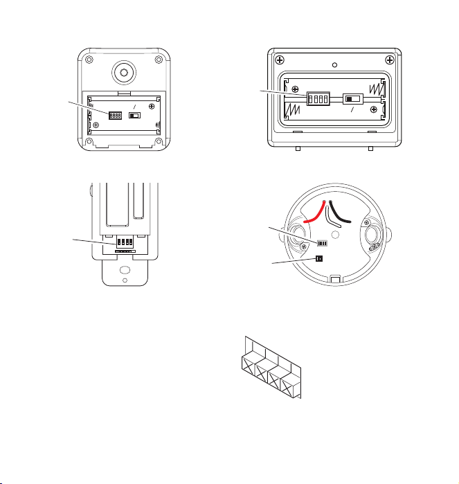
CODE SWITCH LOCATIONS
ON
1 2 3
4
RAINTIGHT
OUTDOOR USE ONLY.
FOR WALL AND CEILING MOUNT ONLY
SUITABLE FOR WET LOCATION
MADE IN CHINA
THIS END UP
ã
Switches
Switches
Code
Code
180° Motion Sensor
Wall Switch Receiver
Note: The “X” has been
placed on the switches to
help clarify the code settings
on the previous page.
Close-Up of Typical Code Switch
(Factory Default Setting is Off)
Code
Switches
240° Motion Sensor
Code
Switches
LAMP MODE
switches
Floodlight
2 598-1306-02
Page 3
DETECT
CODES
1 2 3 4
DAY
NIGHT
NIGHT
ONLY
DETECT
CODES
12 3 4
DAY
NIGHT
NIGHT
ONLY
180° AND 240° MOTION SENSORS
Detect
Control
240° Motion Sensor
180° Motion Sensor
Features:
• No wiring required.
• Up to 70 feet sensing range, 180° or 240° Coverage (Depending
upon model).
• Adjustable sensitivity.
• Day/Night or Night only operation.
• Test mode.
• DualBrite® Mode (240° Motion Sensor Only).
• Uses 2 AA batteries.
• Wall or eave mount.
• Controls receivers up to 100 feet (30 m) away.
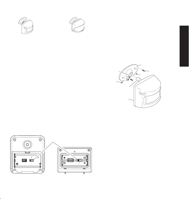
Select Night or 24 Hour Mode
These motion sensors are able to detect motion day and night or
night only. To set the detection mode, remove battery compartment
cover by sliding the cover down. Remove batteries if necessary.
Slide the DETECT switch to either the DAY/NIGHT or NIGHT
ONLY position. Replace battery compartment cover by reversing
the above instructions.
• Before mounting motion sensor, remove battery compartment
cover by sliding the cover down.
Install 2 AA batteries according to polarity markings inside the
battery compartment. Replace battery compartment cover by
reversing the above instructions.
Installing Batteries
1. Install motion sensor mounting bracket where motion detection is
2. Install motion sensor to mounting bracket. Using a Philips-head
IMPORTANT: The motion sensor must be mounted with the bottom
cover facing down in order to maintain water tightness.
Bracket Socket
Installing Motion Sensor
desired. Attach motion sensor mounting bracket to a sturdy object
(i.e. tree, post, house, etc.) using two screws provided. Make
sure unit has an unobstructed view. Note: Attach mounting
bracket vertically if connecting to a curved surface such as a
post.
screwdriver, loosen the clamp screw on the mounting bracket.
Insert swivel ball mount on motion sensor into mounting bracket
socket (Note: You should hear a snap). Aim motion sensor toward
area where detection is desired. Tighten clamp screw.
Mounting
Clamp
Screw
Mounting Bracket
Mounting Screw
Nut
Swivel Ball Mount
Sensor
Installing Motion Sensor
(180° Motion Sensor Shown)
ENGLISH
180° Motion Sensor
(Rear View)
Battery Compartment
240° Motion Sensor
(Rear View)
3598-1306-02
Page 4
RANGE
ON-TIMEDUALBRITE™
MAX
DUSK TO
DAWN
TEST 1 5
(MINS)
6 3
HRS
OFF
MIN
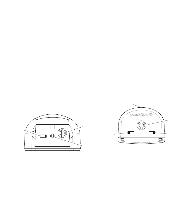
Check Operation and Adjustment
5 1 TEST
ON-TI ME
(MINU TES)
RANGE
MAX
MIN
Note: When rst turned on or when switching modes wait 30
seconds.
Note: Meets the ENERGY STAR® guidelines when DualBrite®
function is off.
Locate the RANGE control and ON-TIME control on the motion
sensor:
• The RANGE control and ON-TIME control are located on the bottom
of the motion sensor. Using your ngernails or a small, at-head
screwdriver, gently pry the cover until it opens.
1. Check Operation. Set the ON-TIME control to TEST mode. Walk in
front of motion sensor. The LED indicator light should ash when
motion is detected (see illustration for location of LED light).
2. Adjust Motion Sensor. Turn the RANGE control to the mid posi-
tion and ON-TIME control to the TEST position. Walk through
coverage area noting where you are when the LED begins to
ash. Loosen the clamp screw and move the motion sensor to
change the coverage area. Tighten clamp screw when nished.
Do not overtighten clamp screw.
3. Adjust RANGE Control. To increase sensitivity, turn the RANGE
control toward MAX. To decrease sensitivity, turn the RANGE
control toward MIN. Note: If the RANGE is set too high, false
triggering may result in some environments.
Note: When using test mode to check operation in the day time:
A. Set the DETECT control switch to DAY/NIGHT and
B. Set the ON-TIME control to TEST.
ON-TIME
Control
180° Motion Sensor Controls
4. Set ON-TIME Control. Determine the amount of time you want
the connected device to stay on after motion is detected (1 or
5 minutes). Slide the ON-TIME control to the corresponding
setting.
DualBrite® Dimmer Control
Light comes on half power for selected time after dusk (Off, 3 or
6 hours, until dawn). When motion is sensed, the light turns on
full power for the selected ON-TIME (1 or 5 minutes) then returns
to accent mode.
1.
Select amount of time desired for accent lighting (DualBrite®
control).
• Off
• 3 Hours
• 6 Hours
• Dusk to Dawn
IMPORTANT: Avoid Aiming Motion Sensor At:
• Objects that change temperature rapidly, such as heating vents,
fans, and air conditioners. These air sources could cause false
triggering.
• Areas where pets or trafc may trigger the control.
• Nearby large, light colored objects reecting light may trigger the
shut-off feature. Do not point other lights at motion sensor.
(240° Motion Sensor Only)
LED Indicator
Range
Control
LED
Indicator
D
ualBrite
Control
®
240° Motion Sensor Controls
4 598-1306-02
Range
Control
ON-TIME
Control
Page 5
8 ft.
(2.4 m)
Maximum Range
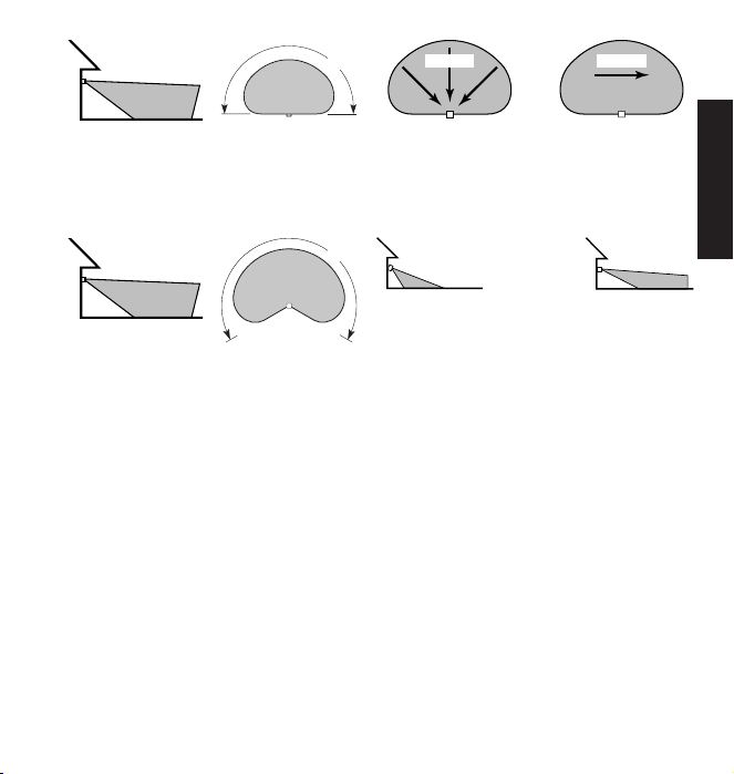
180° Motion Sensor Coverage Area
8 ft.
(2.4 m)
Maximum Range
240° Motion Sensor Coverage Area
70 ft.
(21 m)
70 ft.
(21 m)
Maximum
Coverage Angle
Maximum
Coverage Angle
180°
240°
Motion
Sensor Sensor
The detector is most sensitive to motion across its eld of view.
Aim Sensor Down
for Short Coverage
Motion Sensor Sensitivity
Adjusting Motion Sensor Coverage
Motion
Most SensitiveLeast Sensitive
Aim Sensor Higher
for Long Coverage
ENGLISH
5598-1306-02
Page 6
RECEIVER INFORMATION
All receivers have the following features and ratings:
• Rated for 120VAC/60Hz supply voltage.
• Uses existing wiring.
• Fits standard single gang junction box (wall switch only).
• Not for use with Compact Fluorescent bulbs.
• When rst turned on wait 15 seconds.
WALL SWITCH RECEIVER
Features and Ratings:
• Up to 500 Watt maximum incandescent load depending upon switch purchased. See rating label on switch
for exact load rating.
• Not for use with Compact Fluorescent bulbs.
WARNING: FOR USE ONLY with 120 volt incandescent
or halogen bulbs.
CAUTION: To reduce the risk of overheating and pos-
sible damage to other equipment, do not install to control a
receptacle, a motor-operated appliance, a uorescent lighting
xture, or a transformer-supplied appliance.
Important Information Regarding 3-Way Switch Installations:
In order to use this product where two switches are being used
to control the light, the 3-Way Wall Switch transmitter will also
have to be installed. Refer to the 3-Way Wall Switch Installation section for details.
Important: When ganging these units, they must be derated as
follows:
Gang 1 2 3
300 W 300 W 300 W 300 W
500 W 500 W 475 W 450 W
1. Select light switch to be replaced by wall switch receiver.
2.
WARNING: Turn off the power to the light switch circuit
before you proceed. Do this at your circuit breaker or fuse box.
3. Remove the existing wall plate and switch. Disconnect the two
power wires and the ground wire.
Note: If there are more than two power wires attached to the switch,
consult an electrician about installation. In addition, some local build-
ing codes may require installation by a qualied electrician.
Installation
4. If necessary, strip away 1/2" of insulation from end of wires.
5. Connect one of the black power wires from receiver to one of the
power wires you removed from the old switch. Use one of the
supplied wire connectors to secure the wires (see illustration).
6. Connect the second black power wire from receiver to the other
power wire you removed from the old switch. Use one of the
supplied wire connectors to secure the wires (see illustration).
7. Connect the green ground wire from receiver to the ground
wire removed from old switch. Use one of the supplied wire
connectors to secure the wires (see illustration).
8. Check wire connections to make sure they are secure and that
no bare wires are exposed.
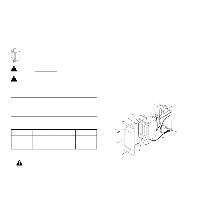
9. Route antenna between the bottom of the junction box and the
wall. Feed antenna into wall cavity while placing wall switch
into junction box.
10. Position the wall switch receiver in the junction box with the DIM
button located to the right. Use the two wall switch screws (long)
supplied to mount the receiver to the wall box (see illustration).
Push excess wiring into wall box while you do this. You may
need to bend the wires to t inside the box. Mount wall plate on
wall switch receiver with screws (short) provided.
11. Turn on the power to the light switch circuit. Do this at your
circuit breaker or fuse box.
Ground Wire (Bare or Green)
ON/OFF Button
Wall Switch Screw
Wall Plate
Screw
Wall Plate
Wall
Switch
DIM Button
Power Disconnect Switch
Installing Wall Switch Receiver
Antenna
Junction
Box
Wall
6 598-1306-02
Page 7

1. Verify the power disconnect switch is in the ON (right side)
position.
2. Push the ON (top) button and release. The light should turn on
full bright. Note: If you are controlling a lamp, make sure it is
connected to the switched outlet and the lamp is switched on.
3. Push the OFF (bottom) button and release. The light should
turn off.
4. Push either the top or bottom of DIM button and release. The
light should turn on at 50% brightness (or last setting).
5. Push and release top of DIM button to increase brightness.
Push and release bottom of DIM button to decrease brightness. Note: There are 5 DIM settings ranging from 15% to 90%
brightness.
Operation
6. Set desired DIM level. Note: DIM setting remembers last
setting used. To recall last DIM setting from ON or OFF, push
and release either the top or bottom of DIM button.
Note: The DIM setting defaults to 50% in the event of a power
failure.
Move the power disconnect switch to the OFF (left side) position.
Replace bulb(s).
CAUTION: Do not exceed the maximum load limits
listed above.
Bulb Replacement
ENGLISH
7598-1306-02
Page 8
FLOODLIGHT
Features and Ratings:
• Up to 150 Watt max imum
incandescent load or 240 Watt
maximum halogen load (up to
or 120 Watt maximum halogen, per lampholder).
• Minimal wiring required.
• Install xture in accordance with local codes.
There are three lamp modes (light turn-on effects) available when
motion is detected:
• NORMAL
• SOFT
brightness. Light gradually dims to half-bright, pauses, and then
continues dimming to off when motion is no longer detected and
after selected ON-TIME.
• FLASH
full brightness.
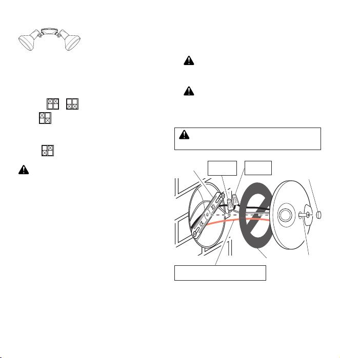
1. Remove the existing light xture.
2. Install the mounting strap as shown using two screws that t
your junction box.
Note: The plastic hanger can be used to hold the xture while
wiring. Thread the small end of the plastic hanger through the
hole in the center of the cover plate. Insert the small end into
one of the slots on the mounting strap.
3. Set the LAMP MODE switch to the desired light turn-on effect
(Normal, Soft, Flash).
4. Route the wires from the light receiver through the large gasket
holes.
5. Twist the junction box wires and xture wires together as shown.
Secure with UL approved wire connectors.
6. Align the cover plate and cover plate gasket. Secure with
mounting bolt.
7. Push the rubber plug rmly into place.
or - Light instantly comes on.
- Light starts dim and gradually increases to full
- Light ashes on then off twice before turning on
WARNING: Turn power off at the fuse or circuit breaker.
75 Watt maximum incandescent,
Lamp Modes
8. Not intended for waterproof junction boxes. Fixture should be
surface mount only. Caulk the wall plate mounting surface with
silicone weather sealant.
9. Adjust the lamp holders by loosening the lock nuts. Note: Do
not rotate the lamp holders more than 180° from the factory
setting.
CAUTION: To avoid water damage and electrical shock,
keep lamp holders 30° below horizontal.
10. Screw incandescent bulb up to rated wattage into module.
When screwing in the lamps, do not overtighten.
CAUTION: Do not exceed the maximum load limits listed
above.
11. Check operation. Activate transmitter being used with receiver
(see transmitter instructions). A signal will be sent to the receiver
to turn the receiver ON or OFF.
WARNING: Risk of re. Do not aim the lamps at a
combustible surface within 3 ft. (1 m).
Mounting
Strap
Junction box ground wire to green
White to
White
ground screw on xture.
Black to
Black
Wiring Floodlight
Gasket
Rubber
Plug
Mounting
Bolt
8 598-1306-02
Page 9
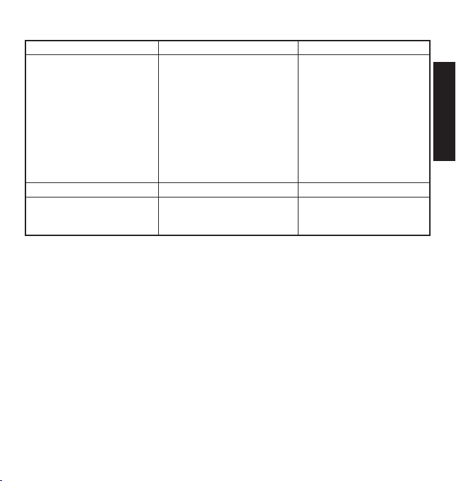
SYMPTOM
Device does not come on.
Device does not turn off.
Device comes on randomly.
TROUBLESHOOTING GUIDE
POSSIBLE CAUSE
1. Circuit breaker or fuse is turned off.
2. Switch on device is turned off.
3. Interrupted by another device.
4. Does not respond immediately after
installation.
5. Signals from tran smitter are being
blocked, or transmitter is out of range.
6. Weak battery in the transmitter.
7. Dip switches on transmitter and receiver
units do not match.
8. Device is defective.
1. Same as 5, 6, and 7 above.
1. Short term power line failure.
2. Anot her tr ansmitt er on the sam e
frequency.
SOLUTION
1. Verify circuit breaker or fuse is turned
on.
2. Verify switched device is turned on.
3. Change codes on transmitter and
receiver units.
4. Wait for 90 second initialization period
(remote motion sensor).
5. Check for metal objects that could
block the signal, or reposition the
transmitter.
6. Check battery charge and replace if
necessary.
7. Verify code settings on transmitter and
receiver units are set the same.
8. Test using different device.
1. Same as 5, 6, and 7 above.
1. Next transmission from transmitter
will reset receiver to correct state.
2. Change codes on transmitter and
receiver units.
ENGLISH
Please call 1-800-858-8501 (English speaking only) for assistance before returning product to store.
TECHNICAL SERVICE
If you experience a problem, follow this guide. You may also want to visit our Web site at: www.hzsupport.com. If the problem persists,
call* for assistance at 1-800-858-8501 (English speaking only), 7:30 AM to 4:30 PM CST (M-F). You may also write* to:
HeathCo LLC
P.O. Box 90004, Bowling Green, KY 42102-9004
ATTN: Technical Service
* If contacting Technical Service, please have the following information available: Model Number, Date of Purchase, and Place of
Purchase.
This device complies with Part 15 of the FCC Rules and RSS-210 of Industry Canada. Operation is subject to the following two conditions:
(1) this device may not cause harmful interference, and (2) this device must accept any interference received, including interference
that may cause undesired operation.
The user is cautioned that changes or modications not expressly approved by the party responsible for regulatory compliance could
void the user’s authority to operate the equipment.
No Service Parts Available for this Product
REGULATORY INFORMATION
9598-1306-02
Page 10

This is a “Limited Warranty” which gives you specic legal rights. You may also have other rights which vary from state to state
or province to province.
For a period of two years from the date of purchase, any malfunction caused by factory defective parts or workmanship will be
corrected at no charge to you.
Not Covered - Repair service, adjustment and calibration due to misuse, abuse or negligence, light bulbs, batteries, and other
expendable items are not covered by this warranty. Unauthorized service or modication of the product or of any furnished
component will void this warranty in its entirety. This warranty does not include reimbursement for inconvenience, installation,
setup time, loss of use, unauthorized service, or return shipping charges.
This warranty covers only HeathCo LLC assembled products and is not extended to other equipment and components that a
customer uses in conjunction with our products.
THIS WARRANTY IS EXPRESSLY IN LIEU OF ALL OTHER WARRANTIES, EXPRESS OR IMPLIED, INCLUDING ANY
WARRANTY, REPRESENTATION OR CONDITION OF MERCHANT ABILITY OR THAT THE PRODUCTS ARE FIT FOR
ANY PARTICULAR PURPOSE OR USE, AND SPECIFICALLY IN LIEU OF ALL SPECIAL, INDIRECT, INCIDENTAL, OR
CONSEQUENTIAL DAMAGES.
REPAIR OR REPLACEMENT SHALL BE THE SOLE REMEDY OF THE CUSTOMER AND THERE SHALL BE NO LIABILITY ON
THE PART OF HEATHCO LLC FOR ANY SPECIAL, INDIRECT, INCIDENTAL, OR CONSEQUENTIAL DAMAGES, INCLUDING
BUT NOT LIMITED TO ANY LOSS OF BUSINESS OR PROFITS, WHETHER OR NOT FORESEEABLE. Some states or provinces
do not allow the exclusion or limitation of incidental or consequential damages, so the above limitation or exclusion may not apply to
you. Please keep your dated sales receipt, it is required for all warranty requests.
HeathCo LLC reserves the right to discontinue products and to change specications at any time without incurring any obligation to
incorporate new features in products previously sold.
TWO YEAR LIMITED WARRANTY
10 598-1306-02
Page 11

Controles de alumbrado
Cumple con las normas ENERGY STAR®
cuando la función DualBrite® está apagada.
Este manua l sirve para los siguientes
productos:
• Transmisores Inalámbricos (Interiores /
Exteriores)
– Detector de movimiento de 180°
– Detector de movimiento de 240°
• Receptores
– Receptor de pared con interruptor
– Reector
GUÍA DE REFERENCIA DE PÁGINAS
Página 13 Página 16 Página 18
Este manual incluye las instrucciones de operación para una variedad de productos a control
remoto. Todos los productos funcionan basándose en el mismo principio y usan la misma
información para la calibración del código. Por favor lea todas las instrucciones y tome en
cuenta cualquier información especíca relativa a su producto en particular.
ADVERTENCIAS:
. PARA USO SÓLO con bombillas incandescentes o halógenas de 120 voltios.
. NO LO USE con bombillas uorescentes, electrodomésticos, fuentes de energía,
alumbrado con bajo voltaje ni con ningún otro aparato eléctrico.
• Productos probados y aprobados por laboratorios UL/cUL y/o FCC/IC.
• Distancia de operación: hasta 100 pies.
Los controles inalámbricos Heath®/Zenith para el alumbrado están diseñados para
trabajar juntos. Simplemente determine cual transmisor(es) le gustaría que controlen
tal(es) receptor(es) y je la calibración del código para emparejar.
CARACTERISTICAS
ESPAÑOL
CALIBRACIONES DEL CÓDIGO
Nota: La mayoría de instalaciones de sólo un sistema no requerirán ningún cambio en la calibración del código. Para que
funcionen juntos los transmisor(es) y los receptor(es) deben
tener la misma calibración de código y de grupo. Los interrupto-
res del 1 al 3 jan el código. El interruptor 4 ja el grupo (A o B).
Vea en la página 14 la ubicación de los interruptores.
Ejemplo 1 - Calibraciones del código, sistema 1
Código del transmisor(es)/
( – Indica la posición del interruptor)
receptor(es)
Grupo “A”
(calibración de fábrica)
Código del transmisor(es)/
receptor(es)
Grupo “B”
© 2007 HeathCo LLC 598-1306-02 S
Ejemplo 2 - Calibraciones del código, sistema 2
Nota: Cuando opere más de un sistema independientemente el uno del
otro, je cada sistema con un código diferente. Hay 8 códigos disponibles al cambiar las calibraciones de los interruptores del 1 al 3.
Código del
receptor(es)
Grupo “A”
11598-1306-02
Page 12

UBICACIONES DE LOS INTERRUPTORES DE CIRCUITO IMPRESO
ON
DETECT
CODES
12 3 4
DAY
NIGHT
NIGHT
ONLY
DETE CT
CODE S
1 2 3 4
DAY
NIGHT
NIGHT
ONLY
ON
1 2 3
4
RAINTIGHT
OUTDOOR USE ONLY.
FOR WALL AND CEILING MOUNT ONLY
SUITABLE FOR WET LOCATION
MADE IN CHINA
THIS END UP
ã
Interruptores
Interruptores
de circuito
impreso
Detector de movimiento de 180° Detector de movimiento de 240°
Interruptores
de circuito
impreso
de circuito
impreso
Interruptores
de circuito
impreso
interruptores
de FASE DE
LÁMPARA
Receptor de pared con interruptor
Nota: La “X” ha sido colocada
en los interruptores para ayudar
a aclarar las calibraciones del
código de la página anterior.
Vista ampliada de un interruptor típico del código
(la calibración hecha en fábrica es OFF- apagado)
12 598-1306-02
Reector
Page 13

DETECT
CODES
1 2 3 4
DAY
NIGHT
NIGHT
ONLY
DETECT
CODES
12 3 4
DAY
NIGHT
NIGHT
ONLY
DETECTORES DE MOVIMIENTO
DE 180° Y 240°
Control
detector
Detector de movimiento
de 240°
Detector de movimiento
de 180°
Características:
• No se requiere cableado.
• Alcance de detección hasta de 70 pies, cobertura de 180° o 240°
(depende del modelo).
• Sensibilidad ajustable.
• Operación diurna/nocturna o sólo nocturna.
• Modo prueba.
• Modo DualBrite® (Sólo Detector de Movimiento de 240°).
• Usa dos baterías AA.
• Montaje en pared o alero.
• Controla los receptores hasta 30 m de distancia.
Seleccione modo nocturno o modo de 24 horas
Estos detectores de movimiento pueden detectar movimiento durante
el día y la noche o sólo en la noche. Para jar el modo de detección,
retire la tapa del compartimiento de la batería deslizándola hacia
abajo. Si es necesario retire las baterías. Mueva el interruptor DETECT
(DETECTAR) ya sea a la posición DAY/NIGHT ó a la posición NIGHT
ONLY (SÓLO NOCHE). Vuelva a colocar el compartimiento de la
batería siguiendo a la inversa las instrucciones indicadas.
• Antes de montar el detector de movimiento, quite la tapa del
Coloque las dos baterías AA según la polaridad marcada dentro del
compartimento de la batería. Vuelva a colocar el compartimiento de
la batería siguiendo a la inversa las instrucciones indicadas.
Instalación de las baterías
compartimiento de la batería deslizando la tapa hacia abajo.
Instalación del Detector de Movimiento
1. Instale el detector de movimiento montando el soporte donde
se quiera tener la detección de movimiento. Fije el soporte de
montaje del detector de movimiento a un objeto resistente (p.
ej.: árbol, poste, casa, etc.) usando los dos tornillos provistos.
Asegúrese que la unidad no tenga obstrucciones en su línea
de mira. Nota: Sujete la consola de montaje verticalmente si
lo instala a una supercie curva como un poste.
2. Instale el detector de movimiento a la consola de montaje.
Usando un destornillador cabeza Philips, aoje el tornillo de
la abrazadera en la consola de montaje. Inserte el montaje
de bola giratoria del detector de movimiento en el enchufe del
soporte de montaje (Nota: usted debería oír un chasquido).
Apunte el detector de movimiento hacia el área donde se desea
la detección. Apriete el tornillo de la abrazadera.
IMPORTANTE: El detector de movimiento debe ser montado
con la tapa infe rior mirando hac ia abajo para ma ntener su
impermeabilidad.
Zócalo de la consola
de montaje
Tornillo de la
abrazadera
Montura giratoria
de bola
Consola de montaje
Tornillo de montaje
Tuerca
Detector
Instalación del detector de movimiento
(Se muestra el Detector de Movimiento de 180°)
ESPAÑOL
Detector de movimiento de
180° (Vista posterior)
Compartimento de la batería
Detector de movimiento
de 240° (Vista posterior)
13598-1306-02
Page 14

RANGE
ON-TIMEDUALBRITE™
MAX
DUSK TO
DAWN
TEST 1 5
(MINS)
6 3
HRS
OFF
MIN
Revisión de la operación y de la regulación
5 1 TEST
ON-TI ME
(MINU TES)
RANGE
MAX
MIN
Nota: Cuando lo prenda por primera vez o cuando cambie de
modalidad espere 1 1/2 minutos.
Nota: Cumple con las normas ENERGY STAR® cuando la función
DualBrite® está apagada.
Localice en el detector de movimiento los controles de ALCANCE
y DURACIÓN:
•
El control de ALCANCE (RANGE) y de DURACIÓN (ON-TIME) se
encuentran en la parte inferior del detector de movimiento. Usando
las uñas de los dedos o un destornillador pequeño de cabeza plana,
haga suavemente palanca en la tapa hasta que se abra.
1. Revise la operación. Ponga el control de DURACIÓN en el modo
TEST (PRUEBA). Camine frente al detector de movimiento. La
luz indicadora LED debe destellar cuando se detecta movimiento
(vea la ilustración para la ubicación de la luz LED).
2. Ajuste el Detector de Movimiento. Gire el control de ALCANCE
a la posición media y el de DURACIÓN a la posición TEST.
Camine por el área de cobertura y note su posición cuando el
LED empiece a destellar. Aoje el tornillo sujetador y mueva
el detector de movimiento para cambiar el área de cobertura.
Cuando termine apriete el tornillo de la abrazadera. No apriete
excesivamente este tornillo.
3. Regule el control de alcance. Para incrementar la sensibilidad,
gire el control de ALCANCE hacia MAX. Para disminuir la
sensibilidad, gírelo hacia MIN. Nota: En algunos ambientes
si el ALCANCE se calibra demasiado alto, puede ocurrir una
falsa activación.
Nota: Cuando use el modo de prueba (Test) para comprobar
el funcionamiento durante el día:
A. Ponga el interruptor del control DETECT (DETECTAR) a
DAY/NIGHT (NOCHE/DÍA) y
B. Ponga el control ON-TIME (DURACIÓN) a TEST.
Control de
DURACIÓN
Control de
alcance
4. Fije el control de DURACIÓN. Determine la cantidad de tiempo
que desea que el dispositivo conectado permanezca encendido
luego que se detecta movimiento (1 ó 5 minutos). Mueva el
control de DURACIÓN a la conguración correspondiente.
Control DualBrite® de reducción de intensidad
(Sólo Detector de Movimiento de 240°)
La lámpara se enciende a media potencia durante el tiempo
seleccionado a partir del crepúsculo (Apagado, 3 o 6 horas,
hasta el amanecer). Cuando se detecta movimiento, la lámpara
se enciende a toda su potencia durante el tiempo seleccionado
con ON-TIME (DURACIÓN) (de 1 a 5 minutos) luego vuelve a
la fase decorativa.
1. Seleccione el lapso de tiempo deseado para el alumbrado
decorativo (con el control DualBrite®).
•
Apagado
• 3 horas
• 6 horas
• Del crepúsculo al amanecer
IMPORTANTE: Evite apuntar el Detector de Movimiento a:
• Objetos que cambian rápidamente la temperatura, como sopla-
deros de la calefacción, ventiladores y acondicionadores de aire.
Estas fuentes de calor podrían ocasionar una activación falsa.
• A áreas en donde las mascotas o el tráco pueden activar el
control.
• En las cercanías de objetos grandes pintados con colores claros
cuyo reejo puede activar el apagado. No apunte otras luces al
detector de movimiento.
Indicador LED
Control de
alcance
Control
DualBrite
®
Control de
DURACIÓN
Controles del Detector de Movimiento de 180°
Indicador
LED
Controles del Detector de Movimiento de 240°
14 598-1306-02
Page 15

2.4 m
180°
Movimiento Movimiento
Alcance máximo
21 m
Área de Cobertura del Detector de Movimiento de 180°
2.4 m
21 m
Alcance máximo
Área de Cobertura del Detector de Movimiento de 240°
Ángulo máximo de
cobertura
Ángulo máximo de
cobertura
Detector Detector
El detector es más sensible a movimientos transversales a su
campo de mira.
Sensibilidad del Detector de Movimiento
240°
Apunte el detector
hacia abajo para una
cobertura menor
Ajuste de la Cobertura del Detector de Movimiento
15598-1306-02
Sensibilidad máximaSensibilidad mínima
Apunte el detector
hacia más arriba para
una cobertura mayor
ESPAÑOL
Page 16

INFORMACIÓN DEL RECEPTOR
Todos los receptores tien en las siguientes características y
potencias nominales:
• Clasicado para un voltaje de alimentación de 120 V CA/60Hz.
• Usa el cableado existente.
• Se adapta a una caja de empalme simple estándar (sólo para
interruptor de pared).
• No se los usa con bombillas uorescentes compactas.
• Cuando lo prenda por primera vez, espere 15 segundos.
RECEPTOR DE PARED CON
INTERRUPTOR
Características y potencia nominal:
• Hasta una carga incandescente máxima de 500
vatios dependiendo del interruptor comprado. Vea
en la placa de valores nominales del interruptor la
potencia nominal exacta de la carga.
• No se usa con tubos uorescentes compactos.
ADVERTENCIA: PARA USO SÓLO con bombillas incan-
descentes o halógenas de 120 voltios.
CUIDADO: Para reducir el riesgo de sobrecalentamiento
y posible daño a otros equipos, no lo instale para controlar
un receptáculo, un artefacto motorizado, un conjunto de luz
uorescente, o un artefacto que usa un transformador.
Información importante sobre instalación de conmutadores
tridireccional:
Con el n de usar este producto donde se está usando dos
conmutadores para controlar un punto de luz, se tendrá
también que instalar un transmisor de pared con conmutador
tridireccional. Para mayor detalle, vea la sección instalación del
transmisor de pared con conmutador tridireccional.
IMPORTANTE: Cuando estas unidades funcionen en grupo, debe
reducirse la potencia como sigue:
Grupo 1 2 3
300 Vatios 300 Vatios 300 Vatios 300 Vatios
500 Vatios 500 Vatios 475 Vatios 450 Vatios
1. Seleccione el interruptor de la lámpara que será reemplazado
por el receptor de pared con interruptor.
2. ADVERTENCIA: Apague la energía al circuito del
interruptor de la lámpara antes de proceder. Haga esto en
su disyuntor o en la caja de fusibles.
3. Retire la placa y el interruptor de pared existentes. Desconecte los
dos conductores de energía y el conductor de conexión a tierra.
Nota: Si hay más de dos conductores de energía conectados al
interruptor, consulte con un electricista sobre esta instalación.
Además algunos códigos locales sobre edicios pueden exigir
que la instalación la realice un electricista calicado.
4. Si es necesario, pelar 1/2 de pulgada de aislamiento desde el
extremo de los cables.
5. Conecte uno de los conductores negros de energía del receptor
a uno de los conductores de energía que retiró del interruptor
viejo. Use uno de los conectores de alambre provistos para
asegurar los conductores (vea la ilustración).
6. Conecte el segundo conductor negro de energía del receptor
al otro conductor de energía que retiro del interruptor viejo.
Use uno de los conectores de alambre provistos para asegurar
los conductores (vea la ilustración).
7. Conecte el conductor verde de conexión a tierra del receptor
al conductor de conexión a tierra retirado del interruptor viejo.
Use uno de los conectores de alambre provistos para asegurar
los conductores (vea la ilustración).
8. Revise las conexiones de los conductores para asegurarse que estén
bien hechas y que no haya conductores desnudos a la vista.
9. Guíe la antena entre la parte inferior de la caja de empalme y
la pared. Inserte la antena en la cavidad de la pared mientras
coloca el interruptor en la caja de empalme.
10. Coloque el receptor de pared con interruptor en la caja de
empalme con el botón atenuador ubicado a la derecha. Use
los dos tornillos provistos (largos) del interruptor de pared para
montar el receptor a la caja. (vea la ilustración). Mientras hace
esto empuje el exceso de cables hacia la caja. Pueda que
necesite doblar los conductores para que se acomoden en
la caja. Monte la placa de pared en el receptor de pared con
interruptor usando los tornillos (cortos) provistos.
11. Encienda la energía al circuito del interruptor de la lámpara.
Hágalo en su disyuntor o en la caja de fusibles.
INSTALACIÓN
16 598-1306-02
Page 17

Conductor de conexión a tierra
Botón ON/OFF
(Encendido/ apagado)
Tornillo del interruptor
de pared
Tornillo de
la placa de
pared
Placa de
pared
Instalación del receptor de pared con interruptor
1. Verique que el desconectador de energía esté en la posición
ON (lado derecho).
2. Pulse y suelte el botón ON (parte superior). La luz debería
encenderse con luminosidad total. Nota: Si está controlando
una lámpara asegúrese que esté conectada a un tomacorriente
con interruptor y que la lámpara esté encendida.
3. Pulse y suelte el botón OFF (parte inferior). La luz debería
apagarse.
4. Pulse y suelte la parte superior o inferior del botón atenuador.
La luz debería encenderse al 50% de su luminosidad (o según
la última calibración).
5. Pulse y suelte la parte superior del botón atenuador (DIM) para
aumentar la luminosidad. Pulse y suelte la parte inferior del botón
atenuador para disminuir la luminosidad. Nota: Hay 5 calibraciones
del atenuador que van del 15% al 90% de la luminosidad.
6. Fije el nivel deseado en el atenuador (DIM). Nota: El atenuador
memoriza la última calibración usada. Para volver a la última
calibración del atenuador ON u OFF, pulse y suelte la parte
superior o inferior del botón atenuador.
Nota: En caso de una falla de energía, la calibración del atenuador
se ja en el ajuste hecho en fábrica del 50%.
(desnudo o verde)
Interruptor de
pared
Antena
Botón atenuador (DIM)
Desconectador de energía
Operación
Caja de
empalme
Pared
Mueva el desconectador de energía a la posición OFF (lado
izquierdo). Reemplace la(s) bombilla(s).
listados arriba.
Reemplazo de la bombilla
CUIDADO: No exceda los límites de carga máximos
ESPAÑOL
17598-1306-02
Page 18

REFLECTOR
Características y potencias nominales:
• Has ta un a car ga in cande scent e
máxima de 150 vatios o una carga
halógena máxima de 240 vatios (hasta
75 vatios máximo de incandescente,
o 120 vatios máximo de halógena por
• Se requiere un cableado mínimo.
• Instale el aparato de acuerdo a los códigos locales.
Hay tres fases de lámpara (efectos al prender la luz) disponibles
cuando se detecta movimiento:
• NORMAL
• SUAVE
a su brillo total. La luz gradualmente disminuye a medio-brillo,
hace pausa, y continúa disminuyendo hasta que se apaga cuando
ya no detecta movimiento y después de seleccionar DURACIÓN
(ON-TIME).
• DESTELLO
antes de prenderse con su brillo completo.
ADVERTENCIA: Desconecte la alimentación en el fusible
o en el disyuntor.
1. Retire el aparato de luz existente.
2. Como se muestra, instale la lámina de montaje usando dos
tornillos que encajen en su caja de empalme.
Nota: Puede usarse un colgador plástico para sostener el aparato
mientras se cablea. Enrosque el extremo pequeño del colgador
plástico en el oricio central de la placa cubertora. Inserte el extremo
pequeño en una de las ranuras de la lámina de montaje.
3. Fije el interruptor de FASE DE lámpara al efecto deseado de
encendido de luz (Normal, Suave, Destello).
4. Guíe los cables desde el receptor para lámpara pasando por
el oricio grande del empaque.
5. Tuerza juntos, como se muestra, los cables de la caja de
empalme con los del aparato. Asegúrelos con conectores de
alambre que tengan aprobación UL.
6. Alinee la placa cubertora con su empaque. Asegúrelos con el
perno de montaje.
7. Empuje rmemente el tapón de caucho hasta su sitio.
cada portalámparas).
Fases De Lámpara
o – La luz se prende instantáneamente.
– La luz comienza tenue y gradualmente aumenta
– La luz se prende y se apaga por dos veces
8. No se lo debe usar con cajas de empalme impermeables. Al
aparato se lo debe instalar sólo sobre una supercie. Calafatee
la supercie de montaje de la placa con un sellador de silicona
contra la intemperie.
9. Regule los portalámparas aojando las contratuercas. Nota: No gire
los portalámparas más de 180° de la calibración de fábrica.
PRECAUCIÓN: Para evitar daño por agua y sacudida
eléctrica mantenga los portalámparas a 30° por debajo de la
horizontal.
10. Enrosque en el módulo una bombilla incandescente cuya
potencia sea hasta la nominal. Cuando la enrosque en la
lámpara no la apriete excesivamente.
PRECAUCIÓN: No exceda los límites de carga máximos
indicados arriba.
11. Revise la operación. Active el transmisor que va a usarse con
el receptor (vea las instrucciones del transmisor). Una señal
será enviada al receptor para ENCENDERLO o APAGARLO.
ADVERTENCIA: Rie sgo de incend io. No apunte
las lámparas a supercies combustibles dentro de un
1 metro.
Lámina de
montaje
Conductor de tierra de la caja de empalme al
tornillo verde de tierra en el aparato.
Blanco con
blanco
Negro con
negro
Empaque
Cableado del reector
Tapón de
caucho
Perno de
montaje
18 598-1306-02
Page 19

SÍNTOMA
El dispositivo no se enciende.
El dispositivo no se apaga.
El dispositivo se enciende al azar.
GUÍA DE ANÁLISIS DE AVERÍAS
CAUSA PROBABLE
1. El disyuntor o el fusible está desconectado.
2. El in terrupto r del disposi tivo est á
desconectado.
3. Interrumpido por otro dispositivo.
4. No responde inmediatamente luego de
la instalación.
5. Las señales desde el transmisor están
siendo bloqueadas o el transmisor está
fuera de alcance.
6. Batería desgastada en el transmisor.
7. Los interruptores de circuito impreso
en el transmisor y los receptores no
emparejan.
8. El dispositivo está defectuoso.
1. Igual que el 5, 6 y 7 anteriores.
1. Falla de corta duración en la línea de
alimentación.
2. Otro transmisor en la misma frecuencia.
SOLUCIÓN
1. Verique que el disyuntor o el fusible
esté conectado.
2. Verique que el dispositivo controlado
con interruptor esté encendido.
3. Cambie los códigos en las unidades
trasmisora y receptora.
4. Espere los 90 segundos del período
de iniciación (detector remoto de
movimiento).
5. Revise objetos metálicos que podrían
bloquear la señal, o vuelva a poner
el transmisor en posición.
6. Revise la carg a de la batería y
reemplace si es necesario.
7. Verifi que que la calibración del
código de las unidades transmisora
y receptora sean iguales.
8. Pruebe usando un dispositivo diferente.
1. Igual que el 5, 6 y 7 anteriores.
1. La siguiente transmisión desde el
transmisor recongurará al receptor
a su estado correcto.
2. Cambie los códigos en las unidades
transmisora y receptora.
ESPAÑOL
Favor de llamar al 1-800-858-8501 (sólo para hablar en inglés) para pedir ayuda antes de devolver el
Si tiene algún problema, siga esta guía. Usted puede también visitar nuestro sitio Web: www.hzsupport.com. Si el problema continúa,
llame al 1-800-858-8501 (sólo para hablar en inglés), de 7:30 AM a 4:30 PM CST (L-V). Usted puede también escribir a:
HeathCo LLC
P.O. Box 90004, Bowling Green, KY 42102-9004
ATTN: Technical Service (Servicio Técnico)
* Si se llama al Servicio Técnico, por favor tener lista la siguiente información: Número de Modelo, Fecha de compra y Lugar de compra.
Este aparato cumple con la Parte 15 de las Reglas de la FCC (Comisión Federal de Comunicaciones) y con la RSS-210 de las Industrias
del Canadá. El funcionamiento está sujeto a las dos siguientes condiciones: (1) este aparato no puede causar interferencias dañinas,
y (2) este aparato debe aceptar cualquier interferencia recibida, incluyendo una interferencia que pueda causar un funcionamiento
indeseable.
Se advierte al usuario que cambios o modicaciones no aprobadas expresamente por la parte responsable de cumplir con los reglamentos podría invalidar la autoridad del usuario para el uso de este equipo.
No hay piezas de servicio disponibles para este producto.
SERVICIO TÉCNICO
producto a la tienda.
INFORMACIÓN REGULATORIA
19598-1306-02
Page 20

Esta es una “Garantía Limitada” que le da a Ud. derechos legales especícos. Usted puede también tener otros derechos que
varían de estado a estado o de provincia a provincia.
Por un período de 2 años desde la fecha de compra, cualquier mal funcionamiento ocasionado por partes defectuosas de
fábrica o mano de obra será corregido sin cargo para Ud.
No cubierto - Servicio de reparación, ajuste y calibración debido al mal uso, abuso o negligencia, bombillas, baterías, u otras
partes fungibles no están cubiertas por esta garantía. Los Servicios no autorizados o modicaciones del producto o de cualquier
componente que se provee invalidarán esta garantía en su totalidad. Esta garantía no incluye reembolso por inconveniencia,
instalación, tiempo de instalación, perdida de uso, servicio no autorizado, o costos de transporte de retorno.
Esta garantía cubre solamente los productos ensamblados por HeathCo LLC y no se extiende a otros equipos o componentes
que el consumidor usa junto con nuestros productos.
ESTA GARANTÍA ESTÁ EXPRESAMENTE EN LUGAR DE OTRAS GARANTÍAS, EXPRESADAS O SOBREENTENDIDAS,
INCLUYENDO CUALQUIER GARANTÍA, REPRESENTACIÓN O CONDICIÓN DE COMERCIABILIDAD O QUE LOS PRODUCTOS SE ADAPTEN PARA CUALQUIER PROPÓSITO O USO EN PARTICULAR, Y ESPECIFICAMENTE EN LUGAR DE
TODOS LOS DAÑOS ESPECIALES, INDIRECTOS, INCIDENTALES Y CONSECUENTES.
LA REPARACIÓN O EL REEMPLAZO DEBERÍA SER LA ÚNICA SOLUCIÓN DEL CLIENTE Y NO HABRÁ RESPONSABILIDAD POR PARTE DE HEATHCO LLC POR CUALQUIER DAÑO ESPECIAL, INDIRECTO, INCIDENTAL O CONSECUENTE,
INCLUIDOS PERO NO LIMITADOS A CUALQUIER PÉRDIDA DE NEGOCIO O GANACIAS SEAN O NO PREVISIBLES. Algunos
estados o provincias no permiten la exclusión o limitación de daños incidentales o consecuentes, de modo que la limitación
o exclusión arriba indicada puede que no se aplique a Ud. Por favor guarde su recibo de venta fechado; se lo requiere para
cualquier solicitud de garantía.
HeathCo LLC se reserva el derecho de descontinuar productos y de cambiar especicaciones, cuando desee, sin incurrir en ninguna
obligación de incorporar las nuevas características en los productos vendidos anteriormente.
GARANTÍA LIMITADA A 2 AÑOS
20 598-1306-02
Page 21

Commandes d’éclairage
Page 23 Page 26 Page 28
Ce guide comprend des directives d’utilisation pour différents produits télécommandés. Tous
Co nfor me a ux ex igen ces EN ERG Y
STARMD lorsque la fonction DualBriteMD
est désactivée.
Ce ma nuel s’ appl ique au x pr oduits
suivants :
• Transmetteurs
• Transmetteurs sans l (intérieur/extérieur)
- Détecteur de mouvement sur 180 °
- Détecteur de mouvement sur 240 °
• Récepteurs
– Interrupteur récepteur mural
– Projecteur
Note : La plupart des installations simples n’exige pas la mo-
dication des codes préréglés. Les codes et les groupes des
transmetteurs et des récepteurs doivent être réglés de façon
identique pour fonctionner ensemble. Les micro-interrupteurs
1 à 3 servent à régler le code. Le micro-interrupteur 4 sert à
sélectionner le groupe (A ou B). Consultez la page 27 pour
connaître l’emplacement des micro-interrupteurs.
Code des transmetteurs/
RÉGLAGE DES CODES
Exemple 1 - Réglage des codes, System 1
récepteurs
(réglage en usine)
ces produits fonctionnent selon les même principes et utilisent les mêmes types de codes.
Veuillez lire toutes les instructions et noter les informations se rapportant spéciquement
à votre produit.
AVERTISSEMENT :
• UTILISER SEULEMENT avec des ampoules 120 V de type incandescent ou
halogène.
• NE PAS UTILISER avec des ampoules uorescentes, des appareils, des sources
d’alimentation, des dispositifs d’éclairage basse tension ou tout autre type de
dispositif électrique.
• Les produits sont testés et approuvés par UL/cUL et FCC/IC.
• La portée opérationnelle est de 30 mètres.
Les commandes d’éclairage Heath®/Zenith sont conçues pour fonctionner ensemble.
Il suft de déterminer quel transmetteur doit commander quel récepteur, puis de
régler les codes correspondants.
Code des transmetteurs/
récepteurs
PAGE DU GUIDE DE RÉFÉRENCE
CARACTÉRISTIQUES
Exemple 2 - Réglage des codes, système 2
Note : Lors de l’utilisation indépendante de plus d’un système, établissez un code différent pour chaque système. Vous pouvez avoir
jusqu’à 8 codes distincts en réglant les 3 micro-interrupteurs.
Code des
Récepteurs
Groupe « A »
FRANÇAIS
Groupe « A »
( – Indique la position du micro-interrupteur)
© 2007 HeathCo LLC 598-1306-02 F
Groupe « B »
21598-1306-02
Page 22

ON
DETECT
CODES
12 3 4
DAY
NIGHT
NIGHT
ONLY
DETE CT
CODE S
1 2 3 4
DAY
NIGHT
NIGHT
ONLY
Micro-
ON
1 2 3
4
RAINTIGHT
OUTDOOR USE ONLY.
FOR WALL AND CEILING MOUNT ONLY
SUITABLE FOR WET LOCATION
MADE IN CHINA
THIS END UP
ã
interrupteurs
EMPLACEMENT DES MICRO-INTERRUPTEURS
Micro-
interrupteurs
Micro-
interrupteurs
Détecteur de mouvement sur 180 °
Interrupteur récepteur mural
interrupteurs
Interrupteurs
du mode
d’éclairage
Note : Le «X» placé sur
les micro-interrupteurs vise
à préciser la position à la
page précédente.
Vue rapprochée d’un micro-interrupteur
(réglage en usine à la position «OFF»)
22 598-1306-02
Détecteur de mouvement sur 240 °
Micro-
Projecteur
Page 23

DETECT
CODES
1 2 3 4
DAY
NIGHT
NIGHT
ONLY
DETECT
CODES
12 3 4
DAY
NIGHT
NIGHT
ONLY
DÉTECTEURS DE MOUVEMENT
SUR 180 ° ET 240 °
Détecteur de mouvement
sur 180 °
Caractéristiques :
• Aucun câblage nécessaire.
• Portée de détection jusqu’à 70 pieds, sur 180 ° ou 240 ° (selon
le mode)
• Sensibilité réglable.
• Fonctionnement Jour/Nuit ou Nuit seulement.
• Mode d’essai.
• Mode DualBriteMD (détecteur de mouvement sur 240 ° seulement).
• Utilise 2 piles AA.
• Montage sur mur ou avant-toit.
• Commande le récepteur sur une distance maximum de 30
mètres.
Sélection du mode de nuit ou du mode 24 heures
Ces détecteurs de mouvement peuvent déceler les mouvements de jour
comme de nuit ou de nuit seulement. Pour régler le mode de détection,
retirez le couvercle du compartiment des piles en le faisant glisser vers
le bas. Enlevez les piles si nécessaire. Glissez l’interrupteur « DETECT
» soit à la position « DAY/NIGHT » (jour/nuit) ou à la position « NIGHT
ONLY » (nuit seulement). Remettez le couvercle du compartiment des
piles en place en le faisant glisser vers le haut.
• Avant d’installer le détecteur de mouvement, retirez le couvercle
du compartiment des piles en le faisant glisser vers le bas.
Installez 2 piles AA en fonction des repères de polarité se trouvant à
l’intérieur du compartiment des piles. Remettez le couvercle du compartiment des piles en place en le faisant glisser vers le haut.
Installation des piles
Détecteur de mouvement
Commande
de détection
sur 240 °
Installation Du Détecteur De Mouvement
1. Installez le support du détecteur de mouvement là où vous
souhaitez détecter les mouvements. Fixez le support à un
objet solide (p. ex. un arbre, un poteau, un mur, etc.) au
moyen des deux vis fournies. Assurez-vous que le détecteur
n’a pas la vue obstruée. Note : Fixez le support de montage à
la verticale lorsqu’il s’agit d’une surface incurvée, par exemple
d’un poteau.
2. Installez le détecteur de mouvement au support de montage.
À l’aide d’un tournevis à pointe cruciforme, desserrez la vis de
serrage sur le support de montage.Insérez le support pivotant à
bille du détecteur de mouvement dans le support (Note : Vous
devriez entendre un « clic ».). Dirigez le détecteur de mouvement
vers la zone à surveiller. Serrez la vis de serrage.
IMPORTANT : Le détecteur de mouvement doit être installé
avec le couvercle inférieur vers le bas pour assurer l’étanchéité
du boîtier.
Douille de support
de montage
Support de montage
Vis de montage
Écrou
Vis de serrage
Monture à rotule
Détecteur
Installation du détecteur de mouvement
(Détecteur de mouvement sur 180 ° illustré)
FRANÇAIS
Détecteur de mouvement
sur 180 ° (arrière)
Compartiment des piles
Détecteur de mouve-
ment sur 240 ° (arrière)
23598-1306-02
Page 24

RANGE
ON-TIMEDUALBRITE™
MAX
DUSK TO
DAWN
TEST 1 5
(MINS)
6 3
HRS
OFF
MIN
Vérication du fonctionnement et du réglage
5 1 TEST
ON-TI ME
(MINU TES)
RANGE
MAX
MIN
Note : Lorsque l’appareil est mis en circuit ou changé de mode,
attendre 30 secondes.
Note: Conforme aux exigences ENERGY STARMD lorsque la fonction
DualBriteMD est désactivée.
Localisez les commandes RANGE et ON-TIME sur le détecteur
de mouvements.
• Les boutons RANGE et ON-TIME sont situés sur la partie inférieure du boîtier du détecteur de mouvement. À l’aide de vos
ongles ou d’un petit tournevis à tête plate, soulevez doucement
le couvercle jusqu’à ce qu’il s’ouvre.
1. Vériez le fonctionnement. Mettez la commande « ON-TIME » au
mode « TEST ». Déplacez-vous devant le détecteur de mouvement. Le voyant indicateur à DEL devrait clignoter lorsqu’un
mouvement est décelé (consultez l’illustration pour l’emplacement
des voyants à DEL).
2. Réglage du détecteur de mouvement. Tournez la commande
« RANGE » à la position centrale et la commande « ON-TIME »
à la position « TEST ». Marchez dans la zone de couverture en
notant l’endroit où vous êtes lorsque le voyant DEL commence à
clignoter. Desserrez la vis de la bride, puis déplacez le détecteur
de sorte qu’il modie la zone de couverture. Serrez la vis de
serrage lorsque vous avez terminé. Ne serrez pas trop la vis de
serrage.
3. Réglez la commande de la portée. Pour augmenter la sensibilité,
tournez la commande « RANGE » vers MAX. Pour diminuer la
sensibilité, tourner la commande « RANGE » à MIN. Note : Si la
commande « RANGE » est réglée trop haut, ceci pourrait causer
un faux déclenchement dans certains environnements.
Note : Lors de l’utilisation du mode Test pour vérier le fonc-
tionnement pendant le jour, :
A. Régler le commutateur DETECT à DAY/NIGHT, puis
B. Régler la commande ON-TIME à TEST.
Commande
« ON-TIME »
Commande
de portée
4. Réglez la commande « ON-TIME ». Déterminez pendant
combien de temps vous voulez que le dispositif connecté
reste allumé après que le mouvement ait été détecté (1 ou 5
minutes). Glissez la commande « ON-TIME » vers le réglage
correspondant.
Gradateur DualBrite
(détecteur de mouvement sur 240 ° seulement)
L’éclairage s’allume à mi-puissance, pendant la période sélectionnée
(Fermé, 3 heures, 6 heures, jusqu’à l’aube), à la tombée de la nuit.
Lorsqu’un mouvement est détecté, l’éclairage s’allume à pleine
puissance pendant le délai sélectionné (1 ou 5 minutes), avant
de repasser à l’éclairage d’accentuation.
1. Sélectionnez la période souhaitée de fonctionnement de
l’éclairage d’accentuation (commande DualBriteMD) :
•
Fermé
• 3 heures
• 6 heures
• De la tombée de la nuit au lever du jour
IMPORTANT : Évitez de diriger le détecteur de mouvement
vers :
• Des objets qui changent rapidement de température, notamment
: évents de chauffage, ventilateurs, appareil de conditionnement
de l’air. Ces sources de chaleur peuvent causer un faux déclenchement.
• Les endroits où les animaux domestiques ou le trafc peuvent
déclencher la commande.
• Les gros objets de couleur claire situés à proximité et qui reètent
la lumière peuvent déclencher la fermeture. Ne dirigez pas d’autre
lumière vers le détecteur de mouvement.
MD
Voyant DEL
Commande
de portée
Commande
DualBrite
MD
Commande
« ON-TIME »
Commandes du détecteur de mouvement sur 180 °
Voyant
DEL
Commandes du détecteur de mouvement sur 240 °
24 598-1306-02
Page 25

2.4 m
180°
Mouvement Mouvement
21 m
Portée maximale
Zone de couverture du détecteur de mouvement sur 180 °
2.4 m
21 m
Portée maximale
Zone de couverture du détecteur de mouvement sur 240 °
Angle de couverture
maximal
Angle de couverture
maximal
Détecteur Détecteur
Le détecteur est plus sensible au mouvement à travers son
champ de vision.
Sensibilité du détecteur de mouvement
240°
Dirigez le détecteur
vers le bas pour une
couverture courte
Réglage de la couverture du détecteur de mouvement
25598-1306-02
Le plus sensibleLe moins sensible
Dirigez le détecteur
plus haut pour une
couverture longue
FRANÇAIS
Page 26

INFORMATIONS SUR LE RÉCEPTEUR
Tous les récepteurs ont les caractéristiques et valeurs nominales
suivantes :
• Valeur nominale pour une tension de 120 VCA/60 Hz.
• Servez-vous des ls en place.
• Convient à une boîte de connexion standard (interrupteur mural
seulement).
• N’utilisez pas cet appareil avec des ampoules uorescentes
compactes.
• Lorsque l’appareil est mis en circuit, attendre 15 secondes.
INTERRUPTEUR RÉCEPTEUR MURAL
Fonctions et caractéristiques
• Puissance maximum d’éclairage incandescent de
500 W, compte tenu du type d’interrupteur acheté.
Consultez l’étiquette apposée sur l’interrupteur pour
connaître la charge exacte.
• Non conçu pour les ampoules uorescentes compactes.
AVERTISSEMENT : UTILISER SEULEMENT avec des am-
poules 120 V de type incandescent ou halogène.
ATTENTION : Pour réduire les risques de surchauffe et de
dommage à l’équipement, n’installez pas cet appareil pour
contrôler un boîtier de commande, un appareil avec moteur
électrique, un luminaire à uorescent ou un dispositif doté
d’un transformateur.
Infomations Importantes Concernant L’Installation De L’Interrupteur À Trois Voies : An d'utiliser ce produit là où deux
interrupteurs sont utilisés pour contrôler l'éclairage, l'émetteur
de l'interrupteur mural à trois voies doit également être installé.
Référez-vous à la section sur l'installation de l'interrupteur mural
à trois voies pour de plus amples détails.
: Lors de l’installation de multiples interrupteurs, il faut
IMPORTANT
en réduire graduellement la puissance comme suit :
Puissance nominale 1 2 3
300 W 300 W 300 W 300 W
500 W 500 W 475 W 450 W
1. Sélectionnez l’interrupteur à remplacer.
2. AVERTISSEMENT : Coupez l’alimentation de l’interrup-
teur avant de commencer. Pour ce faire, coupez le courant
au panneau de disjoncteurs ou à la boîte à fusibles.
3. Retirez la plaque murale et l’interrupteur existant. Débranchez
les deux ls d’alimentation et le l de mise à la terre.
Installation
Note : S’il y a plus de deux ls d’alimentation raccordés à l’inter-
rupteur, consultez un électricien pour procéder à l’installation. De
plus, le code de l’électricité local pourrait exiger que l’installation
soit conée à un électricien qualié.
4. Si nécessaire, dénudez 1/2 po d’isolant à l’extrémité des ls.
5. Raccordez l’un des ls noirs d’alimentation du transmetteur à
l’un des ls d’alimentation débranchés de l’ancien interrupteur.
Servez-vous des connecteurs fournis pour xer les ls ensemble
(voir l’illustration).
6. Raccordez le second l noir du transmetteur à l’autre l d’alimentation débranché de l’ancien interrupteur. Servez-vous
des connecteurs fournis pour xer les ls ensemble (voir
l’illustration).
7. Raccordez le l vert de mise à terre du transmetteur au l de mise
à la terre de l‘ancien interrupteur. Servez-vous des connecteurs
fournis pour xer les ls ensemble (voir l’illustration).
8. Assurez-vous que les ls sont solidement branchés et qu’aucune
partie dénudée n’est exposée.
9. Faites passer l’antenne entre le bas de la boîte de connexion
et le mur. Insérez l’antenne dans la cavité murale en replaçant
le transmetteur dans la boîte de connexion.
10. Insérez l’interrupteur transmetteur mural dans la boîte de connexion
en vous assurant que le bouton du rhéostat (DIM) est situé à droite.
Servez-vous des deux grandes vis fournies pour xer le transmetteur
à la boîte de connexion (voir l’illustration). Repoussez les ls dans la
boîte pendant l’opération. Vous pourriez avoir à les replier pour les
insérer dans la boîte. Installez la plaque murale sur le transmetteur
au moyen des petites vis fournies.
11. Rétablissez le courant au niveau du panneau de disjoncteurs
ou de la boîte à fusibles.
Fil de mise à la terre (dénudé ou vert)
Interrupteur (ON/OFF)
Vis de xation
Vis de plaque
murale
Plaque
murale
Installation de l’interrupteur transmetteur mural
Récepteur
mural
Bouton du rhéostat
Interrupteur d’alimentation
Antenne
Boîte de
connexion
Mur
26 598-1306-02
Page 27

1. Assurez-vous que l’interrupteur d’alimentation est en position
ON (placé du côté droit).
2. Appuyez sur le bouton ON (partie du haut) puis relâchez-le. L’éclairage devrait s’allumer à pleine intensité. Note : Pour commander le
fonctionnement d’une lampe, assurez-vous qu’elle est branchée
à la bonne prise de courant et qu’elle est allumée.
3. Appuyez sur le bouton OFF (partie du bas), puis relâchez-le.
L’éclairage devrait s’éteindre.
4. Appuyez sur la partie supérieure ou inférieure du bouton DIM,
puis relâchez-le. L’éclairage devrait s’allumer à 50 % de l’intensité
maximum (ou en fonction du dernier réglage utilisé).
5.
Appuyez sur la partie supérieure du bouton DIM pour augmenter
l’intensité. Appuyez sur la partie inférieure du bouton DIM pour diminuer
l’intensité de l’éclairage. Note : Le bouton DIM comprend cinq
degrés de réglage de l’intensité qui varie de 15 % à 90 %.
6. Réglez l’éclairage à l’intensité désirée. Note : Le rhéostat
mémorise le dernier réglage utilisé. Pour le rappeler au moyen
de l’interrupteur, appuyez sur la partie supérieure ou inférieure
du bouton DIM, puis relâchez-le.
Note : En cas de panne de courant, le réglage de l’intensité revient
automatiquement à 50 %.
Fonctionnement
Placez l’interrupteur d’alimentation en position OFF (du côté
gauche). Remplacez l‘ampoule.
rieure à ce qui est inscrit dans les caractéristiques plus haut.
Remplacement de l’ampoule
ATTENTION : Évitez d’utiliser une ampoule de puissance supé-
FRANÇAIS
27598-1306-02
Page 28

PROJECTEUR
Caractéristiques et valeurs nominales :
• Jus qu’à 150 wat ts m axim um de
charge incandescente ou 240 watts
de charge halogène (jusqu’à 75 watts maximum de charge
incandescente ou 120 watts maximum de charge halogène par
douille).
• Minimum de câblage nécessaire.
• Installez l’appareil conformément aux codes locaux en v igueur.
Trois modes d’éclairage (façon dont l’éclairage se déclenche) sont
proposés lorsqu’un mouvement est détecté :
• NORMAL
• DOUX (SOFT)
et celle-ci s’accroît graduellement jusqu’à l’intensité normale.
L’intensité décroît ensuite graduellement jusqu’à la mi-puissance,
fait une pause, puis continue de diminuer jusqu’à la fermeture
totale lorsque le détecteur cesse de déceler un mouvement ou
lorsque la durée de fonctionnement (ON-TIME) est écoulée.
• CLIGNOTEMENT (FLASH)
fois avant de demeurer allumé à pleine puissance.
AVERTISSEMENT: Coupez le courant au fusible ou au
disjoncteur.
1. Enlevez l’appareil d’éclairage existant.
2. Installez le support de montage tel qu’illustré à l’aide de deux
vis convenant au disjoncteur.
Note : Le support de plastique peut être utilisé pour tenir
l’appareil d’éclairage lors du câblage. Faites passer la petite
extrémité du spport de plastique à travers le trou dans le centre
de la plaque-couvercle. Insérez la petite extrémité dans une
des fentes sur le support de montage.
3. Au moyen du bouton LAM P MODE, sélec tionnez l’e ffet
d’éclairage souhaité (NORMAL, DOUX/SOFT ou CLIGNOTEMENT/FLASH).
4. Acheminez les ls à partir du récepteur optique à travers les
gros trous du joint.
5. Torsadez les ls du disjoncteur et les ls de l’appareil d’éclairage
tel qu’illustré. Fixez-les à l’aide des capuchons de connexion
approuvés UL.
6. Alignez la plaque-couvercle et le joint de plaque-couvercle.
Fixez à l’aide d’un boulon de montage.
maximum
Modes D’Éclairage
ou – L’éclairage s’allume instantanément.
– L’éclairage s’allume à faible intensité,
– L’éclairage clignote deux
7. Poussez le bouchon de caoutchouc fermement en place.
8. Non conçu pour les boîtes de raccordement étanches. L’appareil
doit être monté en surface seulement. Calfeutrez la plaque de
montage au moyen d’un agent d’étanchéité à base de silicone.
9. Ajustez les douilles en desserrant les écrous freinés. Note :
Ne tournez pas les douilles de plus de 180° par rapport au
réglage d’usine.
ATTENTION : An d’éviter les dégâts causés par l’eau et les
chocs électriques, gardez les douilles à 30° sous l’horizontale.
10. Vissez l’ampoule incandescente à valeur nominale recommandée dans le module. Ne serrez pas outre mesure.
ATTENTION : Ne dépassez pas les limites maximales
de charge gurant ci-dessus.
11. Vériez le fonctionnement. Activez le transmetteur utilisé avec
le récepteur (consultez les directives sur le transmetteur). Un
signal est transmis au récepteur pour le mettre SOUS ou HORS
tension.
AVERTISSEMENT: Risque d’incendie ! Ne pas pointer
les lampes vers une surface combustible située à moins
de 1 mètre.
Support de
montage
Fil de terre du disjoncteur à la vis de terre
verte sur l’appareil d’éclairage.
Blanc à
blanc
Noir à noir
Câblage du projecteur
Joint
Bouchon de
caoutchouc
Boulon de
montage
28 598-1306-02
Page 29

GUIDE DE DÉPANNAGE
SYMPTÔME CAUSE POSSIBLE SOLUTION
Le dispositif ne s'allume pas. 1. Le d isjonct eur ou le f usible sont
Le dispositif ne s'éteint pas. 1. Mêmes cause qu'en 5, 6, et 7 ci-des-
Le dispositif s'allume au hasard. 1. Panne d'électricité de courte de du-
éteints.
2. L'int errupteu r sur le disp ositif e st
éteint.
3. Le dispositif est interrompu par un autre
dispositif.
4. Le dispositif ne répond pas immédia-
tement après l'installation.
5. Les si gnaux du tra nsmett eur so nt
bloqués, ou le transmetteur est hors
de portée.
6. Les piles du transmetteur sont faibles.
7. Les micro-interrupteurs sur le transmetteur et le récepteur ne correspondent
pas les uns aux autres.
8. Le dispositif est défectueux.
sus.
rée.
2. Un autre transmetteur est réglé à la
même fréquence.
1. Vériez que le disjoncteur ou le fusible
sont allumés.
2. Vérif iez q ue l' inter rupteur su r le
dispositif est allumé.
3. Modiez les codes du transmetteur
et du récepteur.
4. Attendez 90 secondes de période
d'initialisation (détecteur de mouvement à distance).
5. Vériez s'il y a des objets métalliques
pouvant bloquer le signal, ou repositionnez le transmetteur.
6. Vériez si les piles sont chargées et
remplacez-les si nécessaire.
7. Assurez-vous que les commutateurs
du transmetteur et du récepteur sont
réglés aux même positions.
8. Vériez si c'est le cas en utilisant un
dispositif différent.
1. Mêmes solutions qu'en 5, 6, et 7
ci-dessus.
1. Lors de la prochaine émission, le
transmetteur replacera le récepteur
à l’état approprié.
2. Modiez les codes du transmetteur
et du récepteur.
Veuillez faire le 1 800 858-8501 (service en anglais seulement) pour obtenir de l’aide avant de retourner
En cas de problème, suivez ce guide. Vous pouvez aussi visiter notre site Web à www.hzsupport.com. Si le problème persiste, composez*
le 1 800 858-8501 (service en anglais seulement), entre 7 h 30 et 16 h 30, HNC, du lundi au vendredi. Vous pouvez aussi écrire au :
HeathCo LLC
P.O. Box 90004, Bowling Green, KY 42102-9004
ATTN: Technical Service (Service technique)
* Lors d’un appel au service technique, veuillez avoir les renseignements suivants à portée de main : numéro du modèle, date d’achat
et endroit de l’achat.
Ce dispositif est conforme aux exigences de la partie 15 des règles FCC et RSS-210 d’Industrie Canada. Son fonctionnement est sujet
aux deux conditions suivantes: 1) Ce dispositif ne doit pas causer de parasites nuisibles, et 2) ce dispositif doit endurer tous les parasites
reçus, y compris ceux susceptibles de provoquer un fonctionnement intempestif.
Avis à l’utilisateur : Les changements ou modications, qui n’ont pas été explicitement approuvés par l’organisme chargé d’assurer la
conformité aux règlements, pourraient invalider le droit de l’utilisateur à faire fonctionner cet appareil.
Aucune pièce de rechange n’est disponible pour ce produit.
SERVICE TECHNIQUE
l’article au magasin.
RENSEIGNEMENTS DE RÈGLEMENTS
29598-1306-02
FRANÇAIS
Page 30

Il s’agit d’une « Garantie limitée » qui vous confère des droits juridiques spéciques. Vous pouvez également jouir d’autres
droits, variables d’une province à l’autre.
Pendant une période de 2 ans à compter de la date d’achat, toute anomalie de fonctionnement imputable à un vice de matériau
ou de main-d’oeuvre sera corrigée gratuitement.
Exclusions de la garantie - Réparations, réglage et calibrage dus à une mauvaise utilisation, un mauvais traitement ou à la
négligence. Les ampoules, les piles et des autres articles non durables ne sont pas couverts par cette garantie. Le service non
autorisé ou la modication du produit ou d’un ou l’autre de ses composants fournis invalidera totalement la présente garantie.
Cette garantie n’inclut pas le remboursement pour le dérangement, l’installation, le réglage, la perte d’utilisation, le service non
autorisé ou les frais d’expédition pour le renvoi de la marchandise.
La garantie ne couvre que les produits assemblés HeathCo LLC et ne s’étend pas aux autres équipements et composants que
le client pourrait utiliser conjointement avec nos produits.
CETTE GARANTIE TIENT EXPRESSÉMENT LIEU DE TOUTES AUTRES GARANTIES, EXPLICITES OU IMPLICITES, Y
COMPRIS DE TOUTE GARANTIE DE REPRÉSENTATION OU DE CONDITION DE CONVENANCE À LA COMMERCIALISATION OU À L’EFFET QUE LES PRODUITS CONVIENNENT À UN BUT OU À UNE UTILISATION PARTICULIÈRE, ET
SPÉCIFIQUEMENT DE TOUS DOMMAGES SPÉCIAUX, DIRECTS, INDIRECTS OU SECONDAIRES.
LE REMPLACEMENT OU LA RÉPARATION CONSTITUENT LE SEUL RECOURS DU CLIENT ET HEATHCO LLC NE POURRA
ÊTRE TENUE RESPONSABLE DE TOUS DOMMAGES SPÉCIAUX, DIRECTS, INDIRECTS OU SECONDAIRES, Y COMPRIS, SANS S’Y LIMITER, LES PERTES COMMERCIALES ET PERTES DE PROFIT, QU’ELLES SOIENT PRÉVISIBLES OU
NON. Certaines provinces n’autorisent pas l’exclusion ou la limitation des dommages indirects ou secondaires, et la limitation
ou l’exclusion ci-dessus pourrait ne pas s’appliquer à vous. Veuillez conserver le reçu portant la date d'achat; vous en aurez
besoin pour toutes vos demandes liées à la garantie.
HeathCo LLC se réserve le droit de mettre n à la production de ses produits ou d’en modier les spécications à tout moment, et elle
n’est pas tenue d’incorporer les nouvelles caractéristiques de ses produits aux produits vendus antérieurement.
GARANTIE LIMITÉE DE 2 ANS
30 598-1306-02
Page 31

NOTES/NOTAS ________________________
_____________________________________
_____________________________________
_____________________________________
_____________________________________
_____________________________________
_____________________________________
_____________________________________
_____________________________________
_____________________________________
_____________________________________
_____________________________________
_____________________________________
_____________________________________
_____________________________________
_____________________________________
_____________________________________
_____________________________________
31598-1306-02
FRANÇAIS
Page 32

Purchase Information
Información de la compra
Renseignements d’achat
Model #: _______________ Date of Purchase: __________________
Nº de modelo / N° de modèle Fecha de compra / Date d’achat
Staple Purchase Receipt Here
Engrape aquí el recibo de compra
Agrafez le reçu d’achat ici
PLEASE KEEP YOUR DATED SALES RECEIPT,
IT IS REQUIRED FOR ALL WARRANTY REQUESTS.
POR FAVOR GUARDE SU RECIBO DE VENTA FECHADO;
SE LO REQUIERE PARA CUALQUIER SOLICITUD
DE GARANTÍA.
VEUILLEZ CONSERVER LE REÇU PORTANT LA DATE
D'ACHAT; VOUS EN AUREZ BESOIN POUR TOUTES
VOS DEMANDES LIÉES À LA GARANTIE.
32 598-1306-02
 Loading...