

Page 1

Hardwired
Mechanical
Chime
© 2007 598-1223-01
Page 2
-2-
FR
ON
T
REAR
TRAN
S
598-1223-01
CHIME REPLACEMENT INSTALLATION
Note: Electrical work must be in accordance with national and local
electrical codes. If in doubt, consult a qualified electrician.
1. Verify transformer power rating. Power must be supplied from
a 16 Volt AC, 10 Watt or a 16 Volt AC, 15 Watt transformer.
2. Remove cover from existing chime.
3. Label all wires before disconnecting. Using masking tape, mark
each wire according to existing chime terminal markings.
• “F” – Front Push Button Wire
• “T” – Transformer Wire
• “R” – Rear Push Button Wire*
4. Disconnect all wires from existing chime.
5. Remove existing chime base from wall.
6. Determine proper chime base orientation. The chime cover
style may determine orientation.
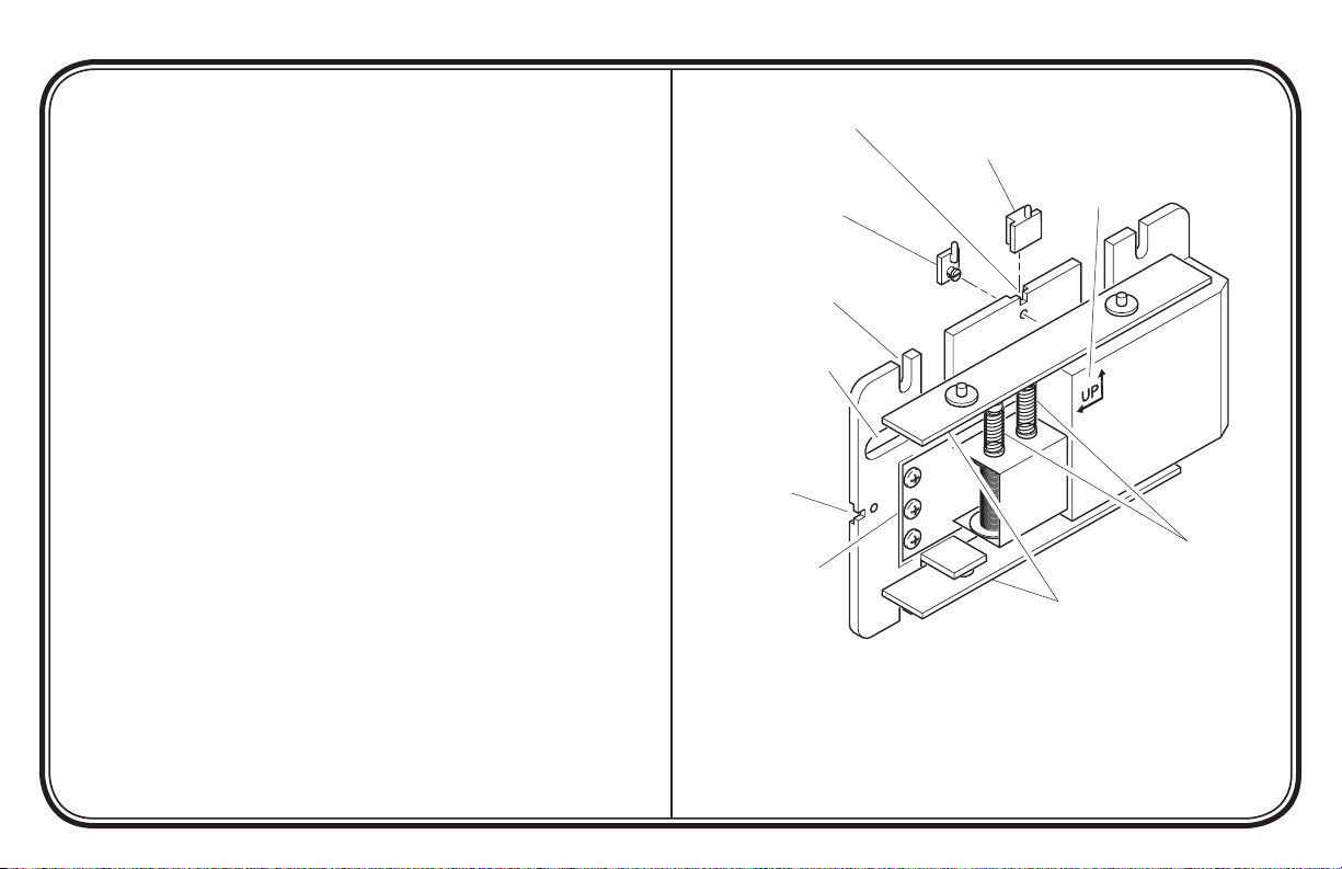
7. Determine cover mounting type. For hang pin and hole type
covers, hang pin should be installed before mounting base to
wall. Install hang pin by snapping into mounting hole or sliding
onto chime base, depending on type of hang pin (see Figures 1
and 3).
Continued
Hang Pin Mounting
Slot (Horizontal)
Hang Pin, Snap-On
Type (Used for Hang
Pin and Hole Covers)
Mounting Slot (x4)
Wire Entrance Hole
Hang Pin Mounting
Slot (Vertical)
Transformer and
Push Button Wire
Connections
Figure 1 - Mechanical Chime Identification
Illustrations may vary from actual chime unit.
Hang Pin, Slide-On Type
(Used for Hang Pin and
Hole Covers)
Base Orientation
Marking
Plungers
Tone Bars
(Model 35 Base Shown)
Page 3
FR
ON
T
RE
A
R
TRAN
S
R
T
F
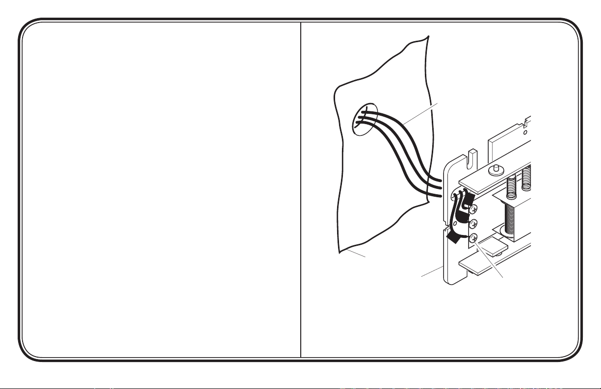
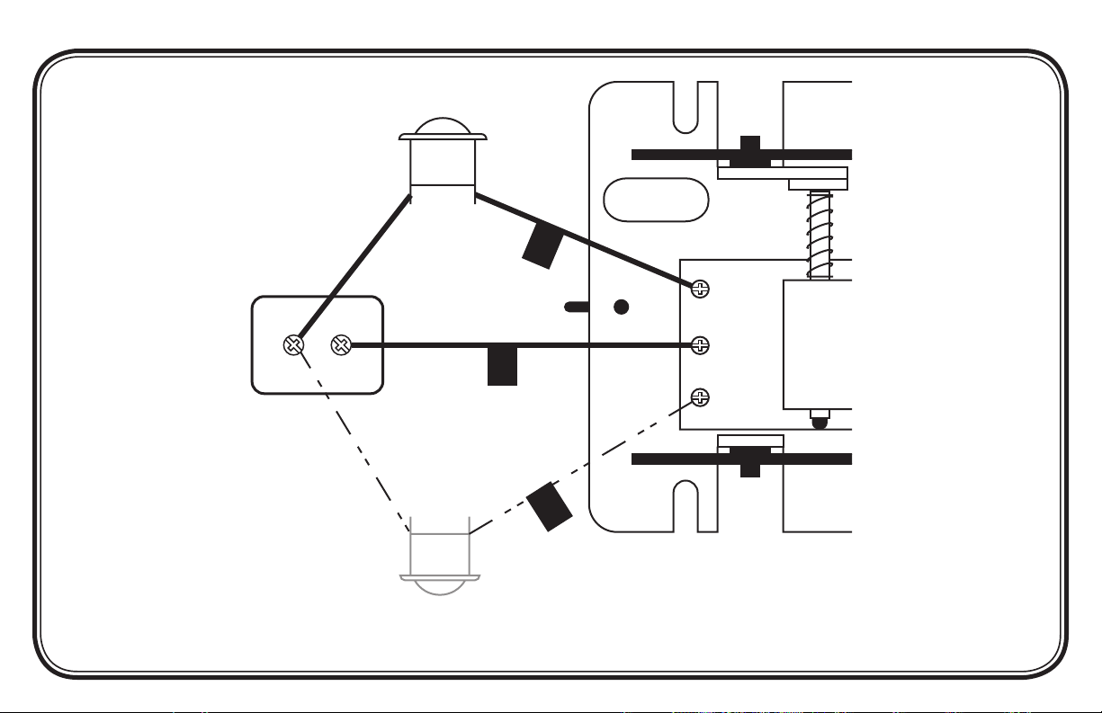
8. Route wires through wire entrance hole in new chime base.
9. Mount chime base to wall using screws provided.
10. Connect wire “F” to screw terminal marked “FRONT”. Connect
wire “T” to screw terminal marked “TRANS”. Connect wire
“R” to screw terminal marked “REAR”* (See Figure 2).
11. Install chime cover (see page 4).
*Note: Some installations may not include rear door push button.
Existing Chime Wires
Wall
Replacement Chime Base
Rear Door Push Button
(if Applicable)
-3-
Figure 2 - Mechanical Chime Wiring
(Model 35 Base Shown)
598-1223-01
Page 4
-4-
FR
O
NT
RE
A
R
TR
A
NS
598-1223-01
INSTALL CHIME COVER
Place chime cover securely over base.
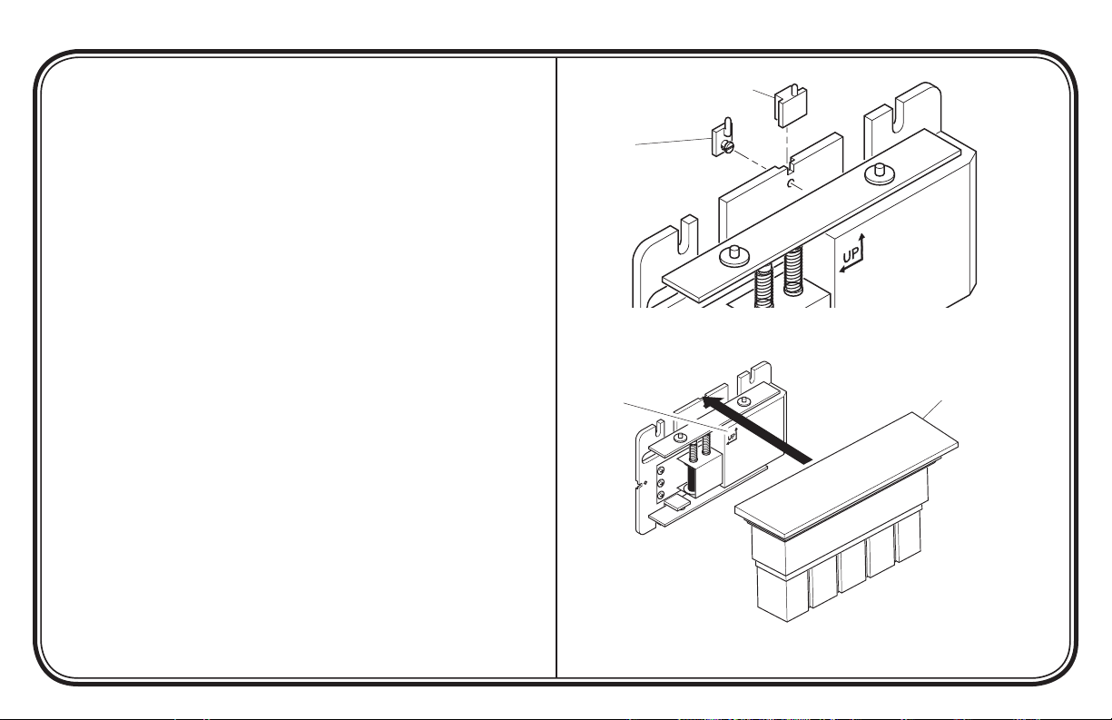
• For hang pin and hole covers: Attach hang pin to base prior
to mounting base on wall. Line up hole in cover with pin and hang
(see Figure 3).
• For snap-on covers: Apply pressure to the cover until it snaps
into place (see Figure 4). Firmly grasp cover and pull to remove
from base.
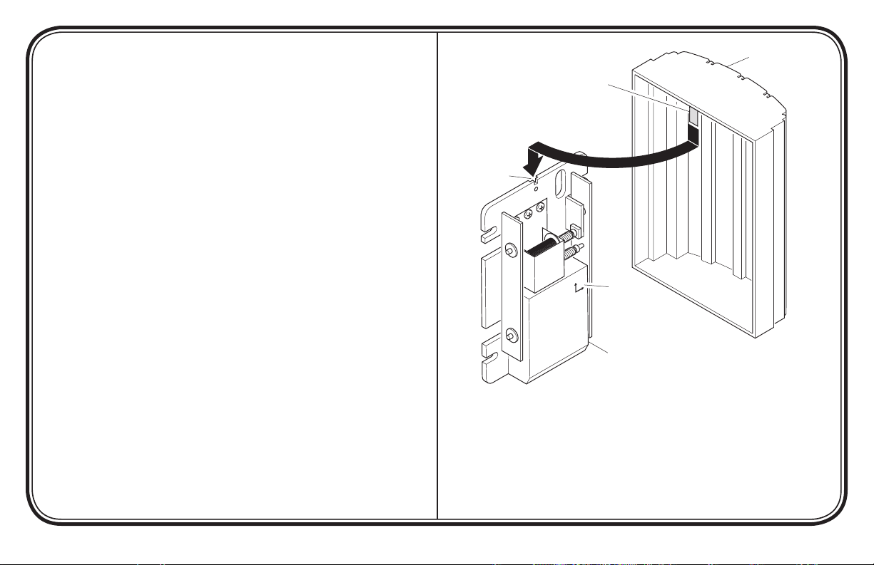
• For hang bracket covers: Determine if the cover will hang
vertically or horizontally on the base. Place bracket into the correct slot inside chime cover.
Adjust bracket (if necessary) so that bracket is flush with back
surface of cover. Slide bracket into slot on base to hang cover (see
Figure 5).
Note: Never use cleaners or polishes. Never use any fluids on the
chime mechanism. Use dry cloth to clean chime cover and base.
Hang Pin, Slide-On Type
Hang Pin,
Snap-On Type
Figure 3 - Pin for Hanging Cover
Base Orientation
Marking
Illustrations may
vary from actual
chime unit.
Snap-On Cover
Figure 4 - Mounting Snap-On Cover
Page 5
FRONT
UP
TRANS
Hang Bracket
Cover
Hang Bracket
Hang
Bracket Slot
Base
Orientation
Marking
Chime Base
(Mounted Vertically)
Figure 5 - Mounting Hang Bracket Cover
-5-
Illustrations may vary from actual chime unit.
598-1223-01
Page 6

-6-
598-1223-01
TROUBLESHOOTING
Chime does not sound:
• Check Chime: Disconnect wire from terminal marked “TRANS”. Have someone operate push button at front door while you mo-
mentarily touch the “TRANS” wire to terminal marked “FRONT”. You will see a small spark if push button, wiring, and transformer
are operating properly. Repeat the steps for “REAR” terminal and rear push button. If wiring between transformer and push button(s)
check out properly, replace chime.
• Check Transformer: Test transformer voltage output with a volt meter. If a volt meter is not available, momentarily touch the two
low-voltage terminals with a screwdriver. You will see a small spark if transformer is operating properly. If no spark is evident, replace
transformer.
• Check Push Button(s): Remove suspected push button from door frame, disconnect wire from terminals and touch bare wires
together. If chime operates, push button is defective. Replace push button.
Page 7

TECHNICAL SERVICE
Please call 1-800-858-8501 (English speaking only) for assistance before returning product to store.
If you experience a problem, follow this guide. You may also want to visit our Web site at: www.hzsupport.com. If the problem persists, call* for assistance at 1-800-858-8501, 7:30 AM to 4:30 PM CST (M-F). You may also write* to:
HeathCo LLC
P.O. Box 90004, Bowling Green, KY 42102-9004
ATTN: Technical Service
* If contacting Technical Service, please have the following information available: Model Number, Date of Purchase, and Place of Purchase.
No Service Parts Available for this Product
This is a “Limited Warranty” which gives you specific legal rights. You may also have other rights which vary from state to state or province to province.
ONE YEAR LIMITED WARRANTY
For a period of one year from the date of purchase, any malfunction caused by factory defective parts or workmanship will be corrected at no charge to you.
Not Covered - Repair service, adjustment and calibration due to misuse, abuse or negligence, light bulbs, batteries, and other expendable items are not
covered by this warranty. Unauthorized service or modification of the product or of any furnished component will void this warranty in its entirety. This warranty does not include reimbursement for inconvenience, installation, setup time, loss of use, unauthorized service, or return shipping charges.
This warranty covers only ACE® assembled products and is not extended to other equipment and components that a customer uses in conjunction with
our products.
THIS WARRANTY IS EXPRESSLY IN LIEU OF ALL OTHER WARRANTIES, EXPRESS OR IMPLIED, INCLUDING ANY WARRANTY, REPRESENTATION
OR CONDITION OF MERCHANT ABILITY OR THAT THE PRODUCTS ARE FIT FOR ANY PARTICULAR PURPOSE OR USE, AND SPECIFICALLY IN
LIEU OF ALL SPECIAL, INDIRECT, INCIDENTAL, OR CONSEQUENTIAL DAMAGES.
REPAIR OR REPLACEMENT SHALL BE THE SOLE REMEDY OF THE CUSTOMER AND THERE SHALL BE NO LIABILITY ON THE PART OF ACE®
FOR ANY SPECIAL, INDIRECT, INCIDENTAL, OR CONSEQUENTIAL DAMAGES, INCLUDING BUT NOT LIMITED TO ANY LOSS OF BUSINESS OR
PROFITS, WHETHER OR NOT FORESEEABLE. Some states or provinces do not allow the exclusion or limitation of incidental or consequential damages,
so the above limitation or exclusion may not apply to you. Please keep your dated sales receipt, it is required for all warranty requests.
ACE® reserves the right to discontinue and to change specifications at any time without notice without incurring any obligation to incorporate new features in previously
sold products.
-7-
598-1223-01
Page 8
R
T
F
FRONT
REAR
TRANS
Front Door
Push Button
Rear Door
Push Button
(If Applicable)
Transformer
-8-
598-1223-01
Chime
Chime System Wiring Diagram
Page 9

Campana con
componentes
mecánicos
© 2007 598-1223-01 S
-9-
598-1223-01
Page 10

-10-
FR
ON
T
REAR
TRAN
S
598-1223-01
INSTALACIÓN DEL REEMPLAZO DE LA
CAMPANA
Nota: El trabajo eléctrico debe estar conforme a los códigos eléctricos nacionales y locales. Si tiene alguna duda consulte con un
electricista calificado.
1. Verifique la potencia nominal del transformador. La energía
debe suministrarse desde un transformador de 16 voltios CA,
10 vatios ó uno de 16 voltios CA, 15 vatios.
2. Retire la tapa de la campana instalada.
3. Antes de desconectar marque todos los conductores. Usando
cinta protectora, marque cada conductor de acuerdo a las marcas
del terminal de la campana.
• “F” – Conductor del pulsador frontal
• “T” – Conductor del transformador
• “R” – Conductor del pulsador posterior*
4. Desconecte todos los conductores de la campana instalada.
5. Retire de la pared la base de la campana instalada.
6. Determine la orientación correcta de la base de la campana. Es
estilo de la tapa de la campana puede determinar la orientación.
7. Determine el tipo de montaje de la tapa. En tapas tipo clavija y
tipo orificio, la clavija de colgar debe instalarse antes de colocar la base a la pared. Instale la clavija de colgar insertándola
a presión en el orificio de montaje o deslizándola sobre la base
de la campana, dependiendo del tipo de clavija de colgar (vea
las Figuras 1 y 3).
Continúa
Ranura de montaje para la
clavija de colgar (horizontal)
Clavija de colgar, tipo a
presión (usada para tapas
tipo clavija y tipo orificio)
Ranura de montaje (x4)
Orificio de entrada
del cable
Ranura de montaje
para la clavija de
colgar (vertical)
Conexiones del
conductor del
transformador y
pulsador
Clavija de colgar, tipo deslizante (usada para tapas
tipo clavija y tipo orificio)
Marca de orientación
de la base
Barras del tonos
Figura 1 - Identificación de la campana mecánica
(Se muestra la base del modelo 35)
Las ilustraciones pueden variar de la unidad de campana real.
Émbolos
Page 11

8. Pase los conductores por el orificio de entrada de cables de la
FR
ON
T
RE
A
R
TRAN
S
R
T
F
base nueva de la campana.
9. Monte la base de la campana a la pared usando los tornillos
provistos.
10. Conecte el conductor “F” al terminal de tornillo marcado
“FRONT”. Conecte el conductor “T” al terminal de tornillo
marcado “TRANS”. Conecte el conductor “R” al terminal de
tornillo marcado “REAR”* (vea la Figura 2).
11. Instale la tapa de la campana (vea la página 12).
*Nota: En algunas instalaciones pueda que no se incluya el pulsador
para la puerta posterior.
Conductores de la
campana instalada
Pared
Base de la campana
de reemplazo
-11-
Figura 2 - Cableado de la campana mecánica
(Se muestra la base del modelo 35)
Pulsador de la puerta
posterior (si se usa)
598-1223-01
Page 12

-12-
FR
O
NT
RE
A
R
TR
A
NS
598-1223-01
INSTALE LA TAPA DE LA CAMPANA
Coloque bien la tapa de la campana sobre la base.
• Para tapas tipo clavija y las tapas de orificio: Acople la
clavija de colgar a la base antes de montar la base en la pared.
Alinee el orificio de la tapa con la clavija y cuélguela (vea la
Figura 3).
• Para tapas de cierre a presión: Aplique presión a la tapa
hasta que cierre a presión en su sitio (vea la Figura 4). Agarre con
firmeza la tapa y hálela para retirarla de la base.
• Para tapas con soporte de colgar: Vea si a la tapa se la cuelga
en la base de forma vertical u horizontal. Coloque el soporte en
la ranura correcta de la tapa de la campana.
Regule el soporte (si es necesario) para que quede a ras con la
superficie posterior de la tapa. Deslice el soporte en la ranura para
colgar la tapa (vea la Figura 5).
Nota: No use nunca limpiadores ni pulidores. No use nunca ningún
líquido en el mecanismo de la campana. Use un paño seco para
limpiar la tapa y la base de la campana.
Clavija de colgar,
tipo deslizante
Clavija de colgar,
tipo a presión
Figura 3 - Clavija para colgar la tapa
Marca de orientación
de la base
Las ilustraciones pueden
variar de la unidad de
campana real.
Tapa de cierre
a presión
Figura 4 - Montaje de la tapa a presión
Page 13

FRONT
UP
TRANS
Tapa tipo
soporte de
Soporte para colgar
colgar
Ranura para
el soporte
de colgar
Marca de
orientación
de la base
Base de la campana
(montada verticalmente)
Figura 5 - Montaje de la tapa tipo soporte de colgar
-13-
Las ilustraciones pueden variar de la unidad de campana real.
598-1223-01
Page 14

-14-
598-1223-01
ANÁLISIS DE AVERÍAS
La campana no suena:
• Inspeccionar la campana: Desconectar el cable del terminal marcado “TRANS”. Hacer que alguien oprima el botón en la puerta
delantera mientras usted toca brevemente el cable “TRANS” al terminal marcado “FRONT’. Si el botón, cableado, y transformador
están operando bien se observa una pequeña chispa. Repetir los pasos para el terminal “REAR” y el botón posterior. Reemplazar la
campana, si el cableado entre el transformador y el botón(es) está bien.
• Inspeccionar el transformador: Pruebe con un voltímetro la salida de voltaje del transformador. Si no se dispone de un voltímetro,
con un destornillador toque momentáneamente los dos terminales de bajo voltaje. Si el transformador opera bien se observa una chispa
pequeña. Reemplazar el transformador si no se observa una chispa.
• Inspeccionar el botón(es): Retire del bastidor de la puerta el pulsador presumiblemente averiado. Desconecte el conductor de los
terminales y una entre si los conductores desnudos. Si la campana funciona, el botón es defectuoso. Reemplazar el botón.
Page 15

SERVICIO TÉCNICO
Favor de llamar al 1-800-858-8501 (sólo para hablar en inglés) para pedir ayuda antes
de devolver el producto a la tienda.
Si tiene algún problema, siga esta guía. Usted puede también visitar nuestro sitio Web: www.hzsupport.com. Si el problema continúa,
llame al 1-800-858-8501 (sólo para hablar en inglés), de 7:30 AM a 4:30 PM CST (L-V). Usted puede también escribir a:
HeathCo LLC
P.O. Box 90004, Bowling Green, KY 42102-9004
ATTN: Technical Service (Servicio Técnic)
* Si se llama al Servicio Técnico, por favor tener lista la siguiente información: Número de Modelo, Fecha de compra y Lugar de compra.
No hay piezas de servicio disponibles para este producto.
Esta es una “Garantía Limitada” que le da a Ud. derechos legales específicos. Usted puede también tener otros derechos que varían de estado a estado
GARANTÍA LIMITADA A 1 AÑO
o de provincia a provincia.
Por un período de 1 año desde la fecha de compra, cualquier mal funcionamiento ocasionado por partes defectuosas de fábrica o mano de obra será
corregido sin cargo para Ud.
No cubierto - Servicio de reparación, ajuste y calibración debido al mal uso, abuso o negligencia, bombillas, baterías, u otras partes fungibles no están
cubiertas por esta garantía. Los Servicios no autorizados o modificaciones del producto o de cualquier componente que se provee invalidarán esta garantía
en su totalidad. Esta garantía no incluye reembolso por inconveniencia, instalación, tiempo de instalación, perdida de uso, servicio no autorizado, o costos
de transporte de retorno.
Esta garantía cubre solamente los productos ensamblados por ACE® y no se extiende a otros equipos o componentes que el consumidor usa junto con
nuestros productos.
ESTA GARANTÍA ESTÁ EXPRESAMENTE EN LUGAR DE OTRAS GARANTÍAS, EXPRESADAS O SOBREENTENDIDAS, INCLUYENDO CUALQUIER
GARANTÍA, REPRESENTACIÓN O CONDICIÓN DE COMERCIABILIDAD O QUE LOS PRODUCTOS SE ADAPTEN PARA CUALQUIER PROPÓSITO O USO
EN PARTICULAR, Y ESPECIFICAMENTE EN LUGAR DE TODOS LOS DAÑOS ESPECIALES, INDIRECTOS, INCIDENTALES Y CONSECUENTES.
LA REPARACIÓN O EL REEMPLAZO DEBERÍA SER LA ÚNICA SOLUCIÓN DEL CLIENTE Y NO HABRÁ RESPONSABILIDAD POR PARTE DE ACE®
POR CUALQUIER DAÑO ESPECIAL, INDIRECTO, INCIDENTAL O CONSECUENTE, INCLUIDOS PERO NO LIMITADOS A CUALQUIER PÉRDIDA DE
NEGOCIO O GANACIAS SEAN O NO PREVISIBLES. Algunos estados o provincias no permiten la exclusión o limitación de daños incidentales o consecuentes, de modo que la limitación o exclusión arriba indicada puede que no se aplique a Ud. Por favor guarde su recibo de venta fechado; se lo requiere
para cualquier solicitud de garantía.
ACE® se reserva el derecho de descontinuar y de cambiar las especificaciones a cualquier momento, sin previo aviso, sin incurrir en ninguna obligación de tener que
incorporar nuevas características en los productos vendidos anteriormente.
-15-
598-1223-01
Page 16

R
T
F
FRONT
REAR
TRANS
Pulsador de la
puerta frontal
Pulsador de la
puerta posterior
(si se usa)
Transformador
-16-
598-1223-01
Campana
Esquema eléctrico del sistema de la campana
Page 17

Carillon
mécanique
câblé
© 2007 598-1223-01 F
-17-
598-1223-01
Page 18

-18-
FR
ON
T
REAR
TRAN
S
598-1223-01
INSTALLATION DU CARILLON DE RECHANGE
Note : Les travaux d’électricité doivent être conformes aux codes
électriques locaux et nationaux. En cas de doute, consultez un
électricien diplômé.
1. Vérifiez la puissance du transformateur. Celui-ci doit fournir
un courant de 16 V c.a., 10 W, ou de 16 V c.a., 15 W.
2. Retirez le couvercle du carillon existant.
3. Étiquetez tous les fils avant de les débrancher. Au moyen de
ruban-masque, identifiez chacun des fils du carillon en fonction
de la borne à laquelle il est raccordé.
• « F » – Bouton-poussoir de l’entrée principale
• « T » – Fil du transformateur
• « R » – Bouton-poussoir de l’entrée secondaire*
4. Débranchez tous les fils du carillon existant.
5. Enlevez du mur le socle du carillon existant.
6. Déterminez l’orientation appropriée du socle du carillon de
rechange. Le style du couvercle du carillon peut vous aider à
déterminer l’orientation.
7. Déterminez le type de montage du couvercle. Pour un couvercle
avec tige et orifice, la tige doit être mise en place avant d’installer
le socle au mur. Installer la tige en l’enclenchant dans l’orifice
de fixation ou en la faisant glisser dans le socle du carillon, selon
le type de tige (voir les Figures 1 et 3).
Suite
Rainure de fixation de
la tige (horizontale)
Tige, type à pression
(pour un couvercle
avec tige et orifice)
Rainure de fixation (x4)
Orifice d’entrée des fils
Rainure de fixation
de la tige (verticale)
Bornes des fils du
transformateur et
du bouton-poussoir
Tige, type coulissant (pour un
couvercle avec tige et orifice)
Figure 1 - Illustration du carillon mécanique
(avec socle du modèle 35)
Le carillon peut être différent de l’appareil illustré.
Marque d’orientation
du socle
Pistons
Barres de tonalité
Page 19

8. Faites passer les fils par les orifices prévus à cet effet dans le
FR
ON
T
RE
A
R
TRAN
S
R
T
F
socle du nouveau carillon.
9. Fixez le socle du carillon au mur, au moyen des vis fournies.
10. Branchez le fil « F » à la borne « FRONT ». Branchez ensuite
le fil « T » à la borne « TRANS ». Branchez enfin le fil « R » à
la borne « REAR »* (voir la Figure 2).
11. Mettez en place le couvercle du carillon (voir la page 20).
*Note : Dans certains cas, il n’y a pas de bouton-poussoir d’entrée
secondaire.
Fils du carillon existant
Mur
Socle du carillon de rechange
-19-
Figure 2 - Câblage du carillon mécanique
(avec socle du modèle 35)
Bouton-poussoir de l’entrée
secondaire (s’il y a lieu)
598-1223-01
Page 20

-20-
FR
O
NT
RE
A
R
TR
A
NS
598-1223-01
INSTALLATION DU COUVERCLE DU
CARILLON
Installez solidement le couvercle sur le socle.
• Pour couvercle avec tige et orifice :
le socle avant de fixer ce dernier au mur. Alignez l’orifice du
couvercle avec la tige, puis suspendez-le (voir la Figure 3).
• Pour couvercle à pression : Appuyez sur le couvercle jus-
qu’à ce qu’il s’encliquette en place (voir la Figure 4). Agrippez
solidement le couvercle, puis retirez-le du socle.
• Pour couvercle avec support de suspension : Déterminez
si le couvercle sera suspendu à l’horizontale ou à la verticale sur le
socle. Insérez le support dans la rainure appropriée du couvercle.
Réglez le support (au besoin) de façon qu’il soit à égalité avec
la surface arrière du couvercle. Faites glisser le support dans les
rainures du socle pour suspendre le couvercle (voir la Figure 5).
Note : N’utilisez jamais de nettoyant ni de poli à meuble. Ne versez
jamais de liquide sur le mécanisme du carillon. Nettoyez le couvercle
et le socle du carillon au moyen d’un chiffon sec.
Installez la tige sur
Tige, de type coulissant
Tige, de type à
pression
Figure 3 - Tige pour couvercle suspendu
Marque d’orientation
du socle
Le carillon peut
être différent de
l’appareil illustré.
Couvercle
encliqueté
Figure 4 - Tige pour couvercle à pression
Page 21

FRONT
UP
TRANS
Couvercle à
support de
Support de suspension
suspension
Rainure
du support
Marque
d’orientation
du socle
Socle du carillon (installé
à la verticale)
Figure 5 - Installation du couvercle à support
de suspension
-21-
Le carillon peut être différent de l’appareil illustré.
598-1223-01
Page 22

-22-
598-1223-01
DÉPANNAGE
Le carillon n’émet pas de son
• Vérifiez le carillon : Débranchez les fils de la borne « TRANS ». Demandez à une autre personne d’appuyer sur le bouton-poussoir
de l’entrée principale pendant que vous touchez momentanément à la borne « FRONT » au moyen du fil « TRANS ». Si le boutonpoussoir, le fil et le transformateur sont bien installés, vous devriez alors voir une petite étincelle. Répétez ces étapes pour la borne «
REAR » et pour le bouton-poussoir de l’entrée secondaire. Si les fils entre le transformateur et les boutons-poussoirs fonctionnent,
remplacez le carillon.
• Vérifiez le transformateur : Vérifiez la tension de sortie du transformateur au moyen d’un voltmètre. Si vous n’en avez pas à
portée de main, établissez un bref contact avec les deux fils basse tension au moyen d’un tournevis. Si le transformateur fonctionne
correctement, cela produira une petite étincelle. S’il n’y a pas d’étincelle, remplacez le transformateur.
• Vérifiez les boutons-poussoirs : Retirez le bouton-poussoir que vous croyez défectueux du cadre de la porte, débranchez les fils
des bornes, puis établissez un contact entre les deux fils dénudés. Si le carillon fonctionne, c’est que le bouton-poussoir est défectueux;
remplacez-le.
Page 23

SERVICE TECHNIQUE
Veuillez faire le 1 800 858-8501 (service en anglais seulement) pour obtenir
de l’aide avant de retourner l’article au magasin.
En cas de problème, suivez ce guide. Vous pouvez aussi visiter notre site Web à www.hzsupport.com. Si le problème persiste, composez*
le 1 800 858-8501 (service en anglais seulement), entre 7 h 30 et 16 h 30, HNC, du lundi au vendredi. Vous pouvez aussi écrire au :
HeathCo LLC, P.O. Box 90004, Bowling Green, KY 42102-9004
ATTN: Technical Service (Service technique)
* Lors d’un appel au service technique, veuillez avoir les renseignements suivants à portée de main : numéro du modèle, date d’achat et
endroit de l’achat.
Aucune pièce de rechange n’est disponible pour ce produit.
GARANTIE LIMITÉE DE 1 AN
Il s’agit d’une « Garantie limitée » qui vous confère des droits juridiques spécifiques. Vous pouvez également jouir d’autres droits, variables d’une province
à l’autre.
Pendant une période de 1 an à compter de la date d’achat, toute anomalie de fonctionnement imputable à un vice de matériau ou de main-d’oeuvre sera
corrigée gratuitement.
Exclusions de la garantie -
les piles et des autres articles non durables ne sont pas couverts par cette garantie. Le service non autorisé ou la modification du produit ou d’un ou l’autre
de ses composants fournis invalidera totalement la présente garantie.Cette garantie n'inclut pas le remboursement pour le dérangement, l'installation, le
réglage, la perte d'utilisation, le service non autorisé ou les frais d'expédition pour le renvoi de la marchandise.
La garantie ne couvre que les produits assemblés ACE® et ne s’étend pas aux autres équipements et composants que le client pourrait utiliser conjointement avec nos produits.
CETTE GARANTIE TIENT EXPRESSÉMENT LIEU DE TOUTES AUTRES GARANTIES, EXPLICITES OU IMPLICITES, Y COMPRIS DE TOUTE GARANTIE
DE REPRÉSENTATION OU DE CONDITION DE CONVENANCE À LA COMMERCIALISATION OU À L’EFFET QUE LES PRODUITS CONVIENNENT À UN
BUT OU À UNE UTILISATION PARTICULIÈRE, ET SPÉCIFIQUEMENT DE TOUS DOMMAGES SPÉCIAUX, DIRECTS, INDIRECTS OU SECONDAIRES.
LE REMPLACEMENT OU LA RÉPARATION CONSTITUENT LE SEUL RECOURS DU CLIENT ET ACE® NE POURRA ÊTRE TENUE RESPONSABLE
DE TOUS DOMMAGES SPÉCIAUX, DIRECTS, INDIRECTS OU SECONDAIRES, Y COMPRIS, SANS S’Y LIMITER, LES PERTES COMMERCIALES
ET PERTES DE PROFIT, QU’ELLES SOIENT PRÉVISIBLES OU NON. Certaines provinces n’autorisent pas l’exclusion ou la limitation des dommages
indirects ou secondaires, et la limitation ou l’exclusion ci-dessus pourrait ne pas s’appliquer à vous. Veuillez conserver le reçu portant la date d'achat; vous
en aurez besoin pour toutes vos demandes liées à la garantie.
ACE® se réserve le droit de mettre fin à la production de ses produits ou d’en modifier les spécifications à tout moment, et elle n’est pas tenue d’incorporer les nouvelles
caractéristiques de ses produits aux produits vendus antérieurement.
Réparations, réglage et calibrage dus à une mauvaise utilisation, un mauvais traitement ou à la négligence. Les ampoules,
-23-
598-1223-01
Page 24

R
T
F
FRONT
REAR
TRANS
Bouton-poussoir de
l’entrée principale
Bouton-poussoir de
l’entrée secondaire
(s’il y a lieu)
Transformateur
-24-
598-1223-01
Carillon
Diagramme de câblage du carillon
 Loading...