

Page 1

Bowling Green, KY 42101
Premium Hardwired
Electronic Chime
Owner’s Manual
© 2007 HeathCo LLC 598-1215-01
Page 2
-2-
598-1215-01
PREMIUM ELECTRONIC CHIME
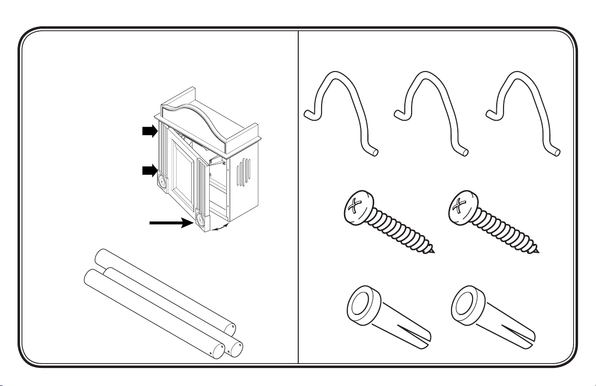
PACKAGE CONTENTS
• 1 - Cover with Base Enclosed
IMPORTANT: Front is hinged
on left side. Be careful when
opening. DO NOT over extend
the front door when opening
or damage to hinges may
occur.
Pull From Here to Open
• 3 - 45" (114 cm) Brass Chime Tubes
Hardware Kit
• 3 - Tube Spring Hangers
• 2 - #8 x 1.5" Screws
• 2 - #8 Wall Anchors
Page 3
CHIME INSTALLATION
IMPORTANT: Proper installation requires a diode on the front
door push button. See Diode Installation Instructions (page 5)
after completing steps 1 through 10 below.
Note: Electrical work must be in accordance with national and local
electrical codes. If in doubt, consult a qualified electrician.
1. Verify transformer power rating. Power must be supplied from
a 16 Volt AC, 10 Watt or a 16 Volt AC, 15 Watt transformer
(Heath®/Zenith models 122C, 121AC, or 125C).
2. Remove cover from existing chime.
3. Label all wires before disconnecting. Using masking tape, mark
each wire according to existing chime terminal markings.
• “F” – Front Push Button Wire
• “T” – Transformer Wire
• “R” – Rear Push Button Wire*
4. Disconnect all wires from existing chime.
5. Remove existing chime base from wall.
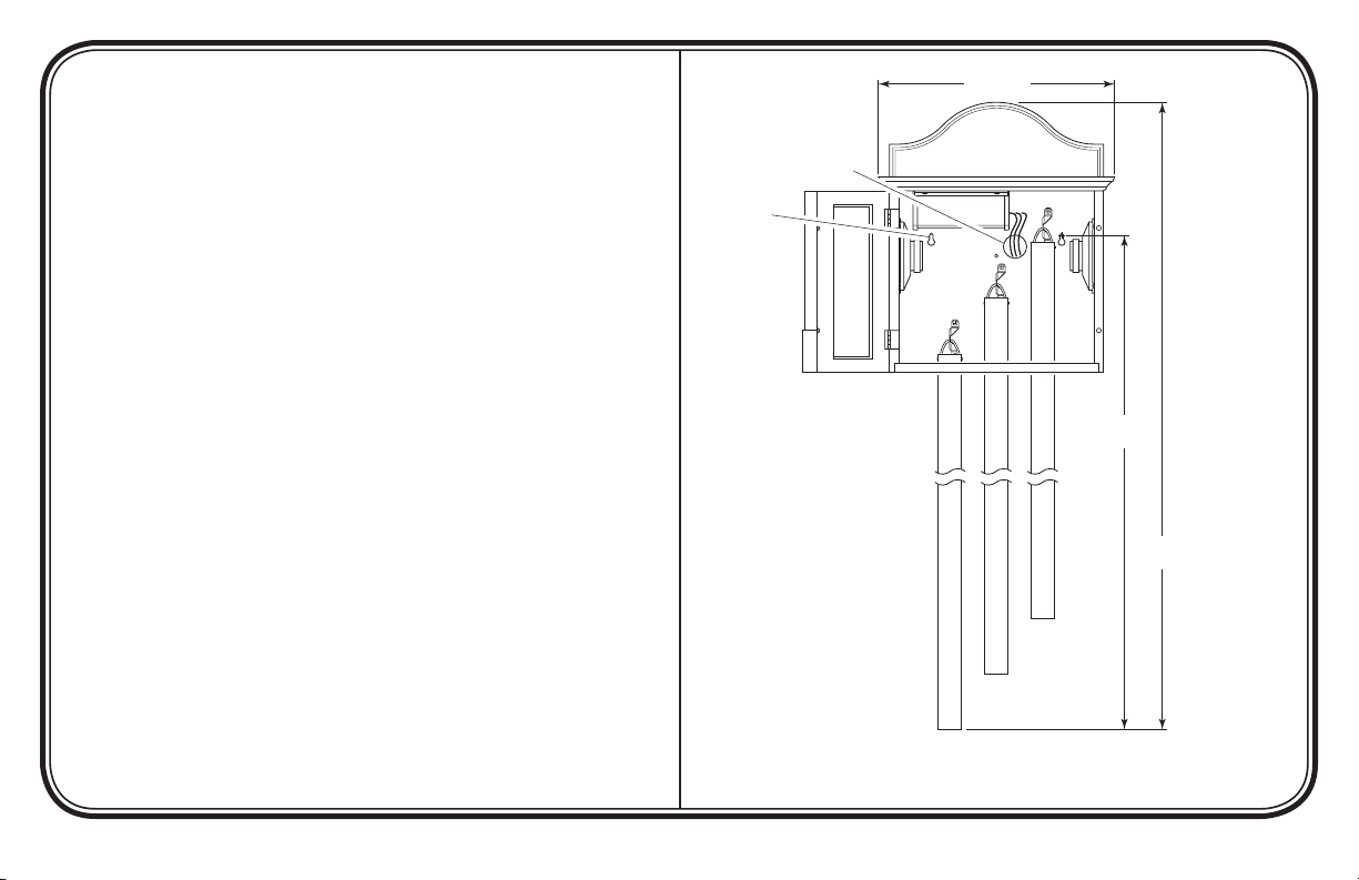
6. Determine chime mounting location. IMPORTANT: This chime
requires more mounting surface than most other chimes. Use
the dimensions in Figure 1 to help determine the proper location of the chime. If chime will not fit in the same location as
the existing chime, then contact a licensed electrician to move
the existing wiring to a more suitable location.
12 11/16"
Wire Entrance Hole
Mounting
Hole (x2)
51 3/8"
58 1/2"
Continued
-3-
Figure 1 - Chime Dimensions
Illustrations may vary from actual chime unit.
598-1215-01
Page 4
-4-
3/8"
F
T
R
R
F
T
598-1215-01
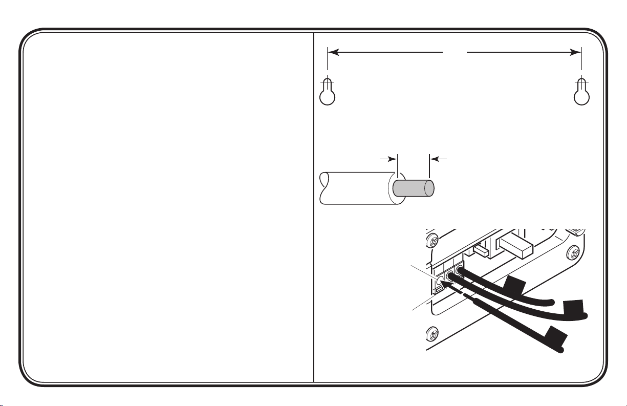
7. Mount chime cover with base to wall using screws and anchors
provided.
• Use the dimensions shown in Figure 2 to properly locate
mounting holes.
• Drill 1/4" (6.4 mm) diameter pilot hole and insert wall an-
chors.
• Insert mounting screws into wall anchors (leave approximately
5/8" (15.9 mm) of the screw threads exposed).
• Route wires through wire entrance hole in new chime base.
• Align mounting keyholes on rear of chime with screws and
place cover on screws.
• Tighten screws securely.
8. Remove 3/8" (9.5 mm) of insulation from each wire and push
wires into the chime quick connects (See Figure 3).
• Push wire “F” into first quick connect terminal.
• Push wire “T” into second quick connect terminal.
• Push wire “R” into third quick connect terminal.
9. Connect diode to front push button (see page 5).
10. Press push button to verify chime works properly. If chime does
not complete eight-note melody, see Troubleshooting, page 8.
* Note: Some installations may not include rear door push button.
7"
Figure 2 - Mounting Screw Location Dimensions
Chime Wire
Quick Connects
To Remove Wires,
Depress Orange Tab
While Pulling Wire Out
of Quick Connect
Figure 3 - Connecting Wires to Chime
Page 5
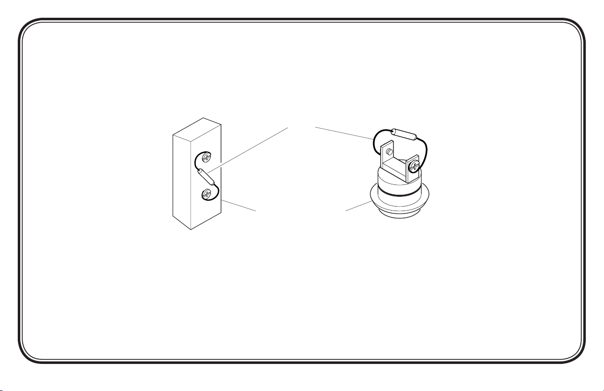
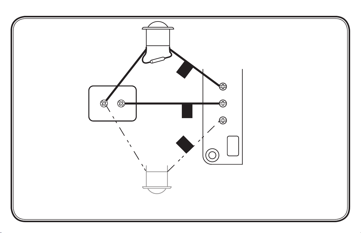
DIODE INSTALLATION INSTRUCTIONS
A small electrical component called a “diode” is required for this chime to play the entire eight-note tune. This diode
must be installed on the terminal screws of the front door push button (see Figure 4). If not already installed on push
button, attach supplied diode as shown below. If, with the diode in place, the chime does not play the complete eight-note melody, see
Troubleshooting, page 8.
Diode
Front Door Push Button
(Styles May Vary)
Figure 4 - Attaching Diode to Front Door Push Button
-5-
598-1215-01
Page 6
-6-
598-1215-01
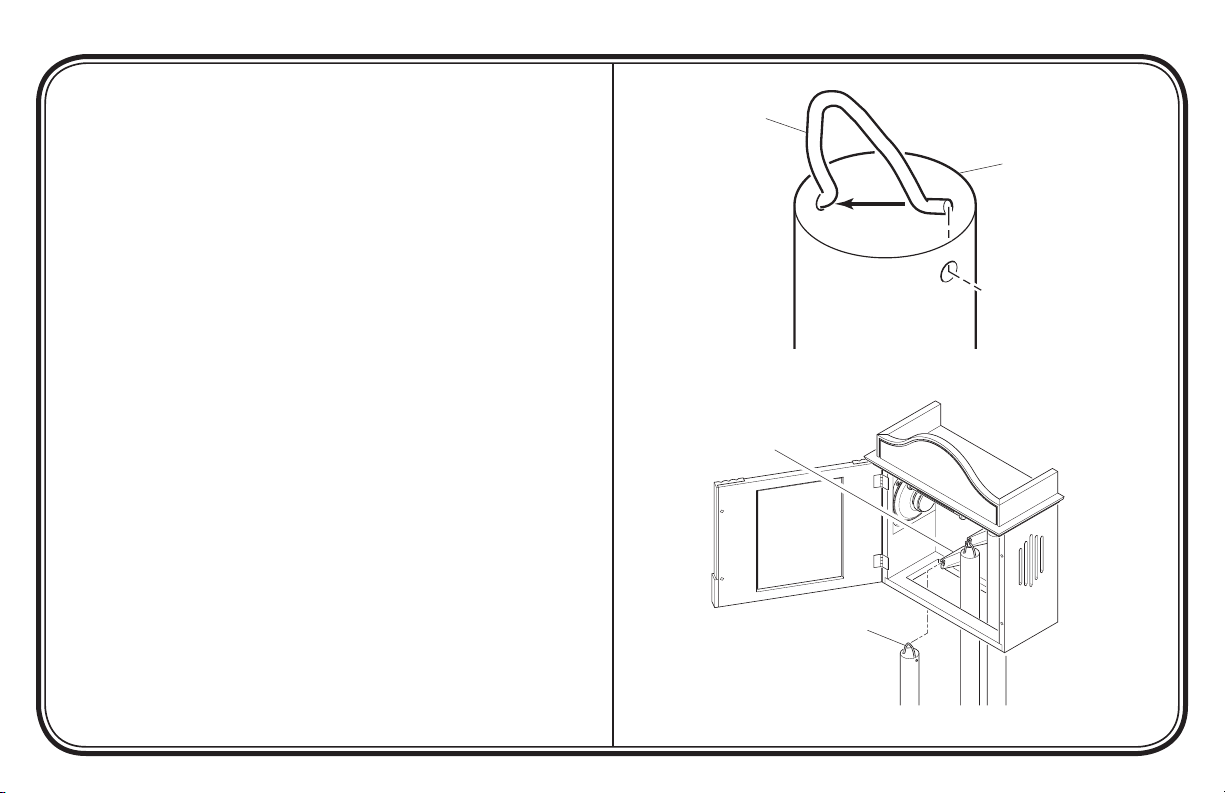
ATTACHING TUBES TO CHIME
Attach Spring Hangers to Brass Tubes
1. Locate the drilled holes in one end of each tube (see Figure 5).
2. Insert one end of spring hanger into one hole.
3. Compress the hanger just enough to insert the other end into
the second hole.
Hang Brass Tubes in Chime
1. Insert tubes through opening in the bottom of the chime (see
Figure 6).
2. Hang the tubes on the hanging brackets using the spring hangers
installed above.
Note: Make sure the spring hanger is securely seated in the notch
on the hanging bracket.
Spring Hanger
Brass Chime Tube
Compress
Figure 5 - Attaching Spring Hangers to Brass Tubes
Hanging Bracket
Spring Hanger
Figure 6 - Hanging Brass Tubes in Chime
Page 7
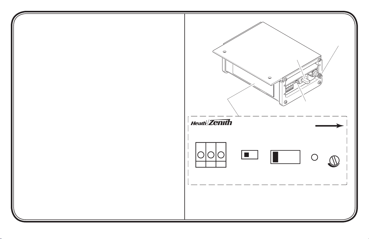
CHIME CONTROLS AND FEATURES
Door/Trans Input
(16 V AC, 10 VA)
F T R
Use Diode On
Front Door Button
Rear Tune
Selector
TR-0055
390-0055XX-TR1A
READ
OWNER’S MANUAL
A B
Front Tune
Selector
Chime Controls
Located On Side
1 2 3 4
Power
ON
LED
Volume
Control
F
T
R
• Volume Control - Rotate volume control to set chime volume as
desired.
• Power “ON” LED - The red LED (Light Emitting Diode) is on
when the unit is properly wired. See Troubleshooting, page 8, if
LED is not on.
• Front Door Tune Selector - This switch allows you to choose
one of four different front door tunes.
• Rear Door Tune Selector - This switch allows you to choose one
of two different rear door tunes.
Instruction Label
Located On Side
of Control Module
Volume Control
Front Door
Tune Selector
Rear Door
Tune Selector
-7-
Figure 7 - Chime Controls
598-1215-01
Page 8

-8-
598-1215-01
TROUBLESHOOTING
Chime does not sound:
• Check Chime: Disconnect wire from terminal marked “T”. Have someone operate push button at front door while you momentarily
touch the “T” wire to terminal marked “F”. You will see a small spark if push button, wiring, and transformer are operating properly.
Repeat the steps for “R” terminal and rear push button. If wiring between transformer and push button(s) check out properly, replace
chime.
• Check Transformer: Test transformer voltage output with a volt meter. If a volt meter is not available, momentarily touch the two
low-voltage terminals with a screwdriver. You will see a small spark if transformer is operating properly. If no spark is evident, replace
transformer.
• Check Push Button(s): Remove suspected push button from door frame, disconnect wire from terminals and touch bare wires
together. If chime operates, push button is defective. Replace push button.
Chime sounds but does not complete Westminster or Whittington (if applicable) tune:
• Check Diode on Front Push Button: Verify diode is attached securely to push button (see page 5). Chime may not function
properly if a diode is installed on more than one push button. Note: Some push buttons have pre-installed diodes. An additional diode
should not be added if the push button has a pre-installed diode. If eight-note tune still does not sound completely, replace diode (Type
1N4001-50V-1A, available at local electrical component supplier).
Page 9

TECHNICAL SERVICE
Please call 1-800-858-8501 (English speaking only) for assistance before returning product to store.
If you experience a problem, follow this guide. You may also want to visit our Web site at: www.hzsupport.com. If the problem persists, call* for assistance at 1-800-858-8501, 7:30 AM to 4:30 PM CST (M-F). You may also write* to:
HeathCo LLC
P.O. Box 90004, Bowling Green, KY 42102-9004
ATTN: Technical Service
* If contacting Technical Service, please have the following information available: Model Number, Date of Purchase, and Place of Purchase.
No Service Parts Available for this Product
This is a “Limited Warranty” which gives you specific legal rights. You may also have other rights which vary from state to state or province to province.
FIVE YEAR LIMITED WARRANTY
For a period of five years from the date of purchase, any malfunction caused by factory defective parts or workmanship will be corrected at no charge to
you.
Not Covered - Repair service, adjustment and calibration due to misuse, abuse or negligence, light bulbs, batteries, and other expendable items are not
covered by this warranty. Unauthorized service or modification of the product or of any furnished component will void this warranty in its entirety. This warranty does not include reimbursement for inconvenience, installation, setup time, loss of use, unauthorized service, or return shipping charges.
This warranty covers only HeathCo LLC assembled products and is not extended to other equipment and components that a customer uses in conjunction
with our products.
THIS WARRANTY IS EXPRESSLY IN LIEU OF ALL OTHER WARRANTIES, EXPRESS OR IMPLIED, INCLUDING ANY WARRANTY, REPRESENTATION
OR CONDITION OF MERCHANT ABILITY OR THAT THE PRODUCTS ARE FIT FOR ANY PARTICULAR PURPOSE OR USE, AND SPECIFICALLY IN
LIEU OF ALL SPECIAL, INDIRECT, INCIDENTAL, OR CONSEQUENTIAL DAMAGES.
REPAIR OR REPLACEMENT SHALL BE THE SOLE REMEDY OF THE CUSTOMER AND THERE SHALL BE NO LIABILITY ON THE PART OF HEATHCO
LLC FOR ANY SPECIAL, INDIRECT, INCIDENTAL, OR CONSEQUENTIAL DAMAGES, INCLUDING BUT NOT LIMITED TO ANY LOSS OF BUSINESS
OR PROFITS, WHETHER OR NOT FORESEEABLE. Some states or provinces do not allow the exclusion or limitation of incidental or consequential damages, so the above limitation or exclusion may not apply to you. Please keep your dated sales receipt, it is required for all warranty requests.
HeathCo LLC reserves the right to discontinue and to change specifications at any time without notice without incurring any obligation to incorporate new features in
previously sold products.
-9-
598-1215-01
Page 10
FRONT TRANS REAR
R
T
F
Transformer
-10-
Front Door
Push Button
With Diode
Rear Door
Push Button
(If Applicable)
598-1215-01
Chime
Illustration may vary from actual chime unit.
Chime System Wiring Diagram
Page 11

Bowling Green, KY 42101
Manual del propietario
de la campana Premium con
componentes electrónicos
© 2007 HeathCo LLC 598-1215-01 S
-11-
598-1215-01
Page 12

-12-
598-1215-01
CONTENIDO DEL PAQUETE DE LA
CAMPANA ELECTRÓNICA PREMIUM
• 1 - Cubierta con base incluida
IMPORTANTE: La parte frontal tiene bisagras al lado
izquierdo. Tenga cuidado al
abrir. Cuando abra la puerta
frontal NO la abra demasiado
ya que pueden dañarse las
bisagras.
Hale de aquí para abrir
• 3 - Tubos de latón de 114 cm (45 pulgadas) de la campana
Juego de ferretería:
• 3 - Perchas de compresión para los tubos
• 2 - Tornillos Nº 8 x 1,5 pulgadas
• 2 - Anclas Nº 8 para pared
Page 13

INSTALACIÓN DE LA CAMPANA
IMPORTANTE: La instalación correcta requiere un diodo en el pulsador de la puerta frontal. Luego de completar los pasos del 1 al 10
que vienen a continuación vea Instrucciones de instalación del diodo
(página 15).
Nota: El trabajo eléctrico debe estar conforme a los códigos eléctricos nacionales y locales. Si tiene alguna duda consulte con un electricista calificado.
1. Verifique la potencia nominal del transformador. La energía debe su-
ministrarse desde un transformador de 16 voltios CA, 10 vatios ó uno
de 16 voltios CA, 15 vatios (Heath®/Zenith modelos 122C, 121AC ó
125C).
2. Retire la tapa de la campana instalada.
3. Antes de desconectar marque todos los conductores. Usando cinta
protectora, marque cada conductor de acuerdo a las marcas del terminal
de la campana.
• “F” – Conductor del pulsador frontal
• “T” – Conductor del transformador
• “R” – Conductor del pulsador posterior*
4. Desconecte todos los conductores de la campana instalada.
5. Retire de la pared la base de la campana instalada.
6. Determine el sitio donde va a montarse la campana. IMPORTANTE: Esta
campana requiere mayor superficie de montaje que la mayoría de otras
campanas. Use las dimensiones mostradas en la figura 1 como ayuda
para determinar el sitio apropiado para la campana. Si la campana no
encaja en el mismo sitio que la campana instalada, póngase en contacto
con un electricista autorizado para mover el cableado instalado a una
ubicación más adecuada.
32,2 cm
Orificio de entrada
del cable
Orificio de
montaje
(x2)
130,5
cm
149,6cm
Continúa
-13-
Figura 1 - Dimensiones de la campana
Las ilustraciones pueden variar de la unidad de campana real.
598-1215-01
Page 14

-14-
3/8"
F
T
R
R
F
T
598-1215-01
7. Monte la cubierta de la campana con la base hacia la pared usando los
tornillos y anclas provistos.
• Use las dimensiones mostradas en la figura 2 para señalar correcta
mente los orificios de montaje.
• Taladre orificios guía de 6,4 mm (1/4 pulgadas) de diámetro e inserte
las anclas para pared.
• Inserte los tornillos de montaje en las anclas (deje aproximadamente
15,9 mm (5/8 pulgadas) de la rosca del tornillo sin insertar).
• Pase los cables por el orificio de entrada de cables de la base de la
campana nueva.
• Alinee los agujeros de montaje de la parte posterior de la campana
con los tornillos y coloque la cubierta en estos tornillos.
• Ajuste bien los tornillos.
8. Retire de cada conductor 9,5 mm (3/8 pulgadas) del aislamiento y
presione los conductores hacia dentro de los conectores rápidos de la
campana (vea la figura 3).
• Presione el conductor “F” insertándolo en el terminal del primer
conector rápido.
• Presione el conductor “T” insertándolo en el terminal del segundo
conector rápido.
• Presione el conductor “R” insertándolo en el terminal del tercer
conector rápido.
9. Conecte el diodo al pulsador frontal (vea la página 15).
10. Presione el pulsador para verificar que la campana funciona correcta
mente. Si la campana no completa la melodía de ocho notas, vea Análisis
de averías, en la página 18.
*Nota: En algunas instalaciones pueda que no se incluya el pulsador para
la puerta posterior.
17,8 cm
-
Figura 2 - Dimensiones para ubicar los tornillos de
montaje
9,5
mm
Conectores rápidos para
conductores de la campana
Para retirar los conductores,
presione la aleta naranja
-
mientras hala al conductor
hacia fuera del conector
rápido
Figura 3 - Conexión de los conductores a la campana
Page 15

INSTRUCCIONES DE INSTALACIÓN DEL DIODO
Para que esta campana toque el tono completo de ocho notas se requiere un pequeño componente llamado “diodo”. Este diodo
puede instalarse en los tornillos terminales del pulsador de la puerta frontal (vea la Figura 5). Si aún no está instalado en el pulsador,
conecte el diodo provisto como se muestra a continuación. Si, con el diodo colocado, la campana no toca la melodía completa de ocho notas, vea Análisis de averías, página 18.
Diodo
Botón de la puerta frontal
(los estilos pueden variar)
Figura 5 - Conexión del diodo al pulsador de la puerta frontal
-15-
598-1215-01
Page 16

-16-
598-1215-01
SUJECIÓN DE LOS TUBOS A LA
CAMPANA
Sujete las perchas de compresión a los tubos de latón
1. Ubique los orificios taladrados en uno de los extremos de cada tubo
(vea la figura 5).
2. Inserte un extremo de la percha de compresión en un orificio.
3. Comprima la percha sólo lo suficiente para insertar el otro extremo en
el segundo orificio.
Cuelgue los tubos de latón en la campana
1. Inserte los tubos por la abertura inferior de la campana (Vea la figura 6).
2. Ponga los tubos en los porta-perchas colgados de las perchas de com
presión recién instaladas.
Nota: Esté seguro que la percha de compresión esté bien asentada en la
muesca del porta-perchas.
Percha de compresión
Tubo de latón de
la campana
Presione
Figura 5 - Sujeción de las perchas de compresión a los
-
Porta-percha
Percha de compression
tubos de latón
Figura 6 - Colgado de los tubos de latón a la campana
Page 17

CONTROLES Y CARACTERÍSTICAS DE
Door/Trans Input
(16 V AC, 10 VA)
F T R
Use Diode On
Front Door Button
Rear Tune
Selector
TR-0055
390-0055XX-TR1A
READ
OWNER’S MANUAL
A B
Front Tune
Selector
Chime Controls
Located On Side
1 2 3 4
Power
ON
LED
Volume
Control
F
T
R
LA CAMPANA
• Control de volumen - Gire el control de volumen para fijar el volumen
de la campana en el nivel deseado.
•
LED de energía “ENCENDIDO”- El LED (diodo emisor de luz) rojo está
encendido cuando la unidad esta cableada correctamente. Si el LED no
está encendido, vea Análisis de averías, página 18.
•
Selector del tono de la puerta frontal - Este interruptor le permite
escoger uno de los cuatro tonos diferentes para la puerta frontal.
•
Selector del tono de la puerta trasera - Este interruptor le permite
escoger uno de los dos tonos diferentes para la puerta trasera.
Etiqueta de instrucciones ubicada
lateralmente en el
módulo de control
Control de volumen
Selector del tono de
la puerta frontal
Selector del tono de
la puerta trasera
-17-
Figura 7 - Controles de la campana
598-1215-01
Page 18

-18-
598-1215-01
ANÁLISIS DE AVERÍAS
La campana no suena:
• Inspeccionar la campana: Desconectar el cable del terminal marcado “T”. Hacer que alguien oprima el botón en la puerta delantera mientras usted
toca brevemente el cable “T” al terminal marcado “F”. Si el botón, cableado, y transformador están operando bien se observa una pequeña chispa. Repetir
los pasos para el terminal “R” y el botón posterior. Reemplazar la campana, si el cableado entre el transformador y el botón(es) está bien.
• Inspeccionar el transformador:
tornillador toque momentáneamente los dos terminales de bajo voltaje. Si el transformador opera bien se observa una chispa pequeña. Reemplazar
el transformador si no se observa una chispa.
• Inspeccionar el botón(es):
una entre si los conductores desnudos. Si la campana funciona, el botón es defectuoso. Reemplazar el botón.
La campana suena pero no completa el tono Westminster o Whittington (si se usa):
• Inspeccionar el diodo en el botón delantero: Verificar que el diodo está bien fijado al botón(Vea la página 15). La campana no puede funcionar
correctamente si se instala un diodo en más de un pulsador. Nota: Algunos pulsadores vienen con los diodos instalados. No se debe añadir un diodo
adicional si el pulsador ya tiene instalado el diodo. Si aún así el tono de ocho notas no suena completamente, reemplace el diodo (Tipo 1N4001-50V1A, disponible donde su proveedor local de componentes eléctricos).
Pruebe con un voltímetro la salida de voltaje del transformador. Si no se dispone de un voltímetro, con un des-
Retire del bastidor de la puerta el pulsador presumiblemente averiado. Desconecte el conductor de los terminales y
Page 19

SERVICIO TÉCNICO
Favor de llamar al 1-800-858-8501 (sólo para hablar en inglés) para pedir ayuda antes
de devolver el producto a la tienda.
Si tiene algún problema, siga esta guía. Usted puede también visitar nuestro sitio Web: www.hzsupport.com. Si el problema continúa, llame al 1800-858-8501 (sólo para hablar en inglés), de 7:30 AM a 4:30 PM CST (L-V). Usted puede también escribir a:
HeathCo LLC
P.O. Box 90004, Bowling Green, KY 42102-9004
ATTN: Technical Service (Servicio Técnic)
* Si se llama al Servicio Técnico, por favor tener lista la siguiente información: Número de Modelo, Fecha de compra y Lugar de compra.
No hay piezas de servicio disponibles para este producto.
Esta es una “Garantía Limitada” que le da a Ud. derechos legales específicos. Usted puede también tener otros derechos que varían de estado a estado
GARANTÍA LIMITADA A 5 AÑO
o de provincia a provincia.
Por un período de 5 años desde la fecha de compra, cualquier mal funcionamiento ocasionado por partes defectuosas de fábrica o mano de obra será
corregido sin cargo para Ud.
No cubierto - Servicio de reparación, ajuste y calibración debido al mal uso, abuso o negligencia, bombillas, baterías, u otras partes fungibles no están
cubiertas por esta garantía. Los Servicios no autorizados o modificaciones del producto o de cualquier componente que se provee invalidarán esta garantía
en su totalidad. Esta garantía no incluye reembolso por inconveniencia, instalación, tiempo de instalación, perdida de uso, servicio no autorizado, o costos
de transporte de retorno.
Esta garantía cubre solamente los productos ensamblados por HeathCo LLC y no se extiende a otros equipos o componentes que el consumidor usa
junto con nuestros productos.
ESTA GARANTÍA ESTÁ EXPRESAMENTE EN LUGAR DE OTRAS GARANTÍAS, EXPRESADAS O SOBREENTENDIDAS, INCLUYENDO CUALQUIER
GARANTÍA, REPRESENTACIÓN O CONDICIÓN DE COMERCIABILIDAD O QUE LOS PRODUCTOS SE ADAPTEN PARA CUALQUIER PROPÓSITO O USO
EN PARTICULAR, Y ESPECIFICAMENTE EN LUGAR DE TODOS LOS DAÑOS ESPECIALES, INDIRECTOS, INCIDENTALES Y CONSECUENTES.
LA REPARACIÓN O EL REEMPLAZO DEBERÍA SER LA ÚNICA SOLUCIÓN DEL CLIENTE Y NO HABRÁ RESPONSABILIDAD POR PARTE DE HEATHCO
LLC POR CUALQUIER DAÑO ESPECIAL, INDIRECTO, INCIDENTAL O CONSECUENTE, INCLUIDOS PERO NO LIMITADOS A CUALQUIER PÉRDIDA DE
NEGOCIO O GANACIAS SEAN O NO PREVISIBLES. Algunos estados o provincias no permiten la exclusión o limitación de daños incidentales o consecuentes,
de modo que la limitación o exclusión arriba indicada puede que no se aplique a Ud. Por favor guarde su recibo de venta fechado; se lo requiere para cualquier
solicitud de garantía.
HeathCo LLC se reserva el derecho de descontinuar y de cambiar las especificaciones a cualquier momento, sin previo aviso, sin incurrir en ninguna obligación de tener
que incorporar nuevas características en los productos vendidos anteriormente.
-19-
598-1215-01
Page 20

FRONT TRANS REAR
R
T
F
Transformador
-20-
Pulsador de la
puerta frontal
con el diodo
598-1215-01
Campana
Pulsador de la
puerta posterior
(si se usa)
Esquema eléctrico del sistema de la campana
La ilustración puede variar de la
campana real
Page 21

Bowling Green, KY 42101
Carillon électronique
câblé de luxe
guide du propriétaire
© 2007 HeathCo LLC 598-1215-01 F
-21-
598-1215-01
Page 22

-22-
598-1215-01
CARILLON ÉLECTRONIQUE DE LUXE
CONTENU DE L’EMBALLAGE
• 1 - Couvercle avec socle
IMPORTANT : La porte comporte des charnières du côté
gauche. Faites bien attention
au moment de l’ouvrir. ÉVITEZ de l’ouvrir trop grand car
vous risqueriez d’endommager les charnières.
Tirez ici pour ouvrir
• 3 - Tubes en laiton de 114 cm (45 po)
Trousse de quincaillerie
• 3 - Supports à ressort pour tube
1
• 2 - Vis n° 8 de 1
/2 po
• 2 - Ancrages muraux n° 8
Page 23

INSTALLATION DU CARILLON
IMPORTANT : L’installation appropriée exige une diode dans le
bouton-poussoir de l’entrée principale. Consultez la section Directives
d’installation de la diode (page 25) après avoir effectué les étapes 1 à
10 ci-après.
Note : Les travaux d’électricité doivent être conformes aux codes électriques
locaux et nationaux. En cas de doute, consultez un électricien diplômé.
1. Vérifiez la puissance du transformateur. Celui-ci doit fournir un courant
de 16 V c.a., 10 W, ou de 16 V c.a., 15 W (modèles HeathMD/Zenith
122C, 121AC ou 125C).
2. Retirez le couvercle du carillon existant.
3. Étiquetez tous les fils avant de les débrancher. Au moyen de rubanmasque, identifiez chacun des fils du carillon en fonction de la borne à
laquelle il est raccordé.
• « F » – Bouton-poussoir de l’entrée principale
• « T » – Fil du transformateur
• « R » – Bouton-poussoir de l’entrée secondaire*
4. Débranchez tous les fils du carillon existant.
5. Enlevez du mur le socle du carillon existant.
6. Déterminez l’endroit où sera installé le carillon.
carillon exige beaucoup plus d’espace que la majorité des carillons
ordinaires. Servez-vous des dimensions de la Figure 1 pour déterminer
l’emplacement qui conviendra au carillon. Si le carillon ne peut être
installé à la même place que l’ancien, contactez un électricien pour
déplacer les câbles existants vers un endroit qui conviendra mieux.
IMPORTANT : Ce
32,2 cm
Orifice d’entrée
des fils
Orifice de
fixation (x2)
130,5
cm
149,6cm
Suite
-23-
Figure 1 - Dimensions du carillon
Le carillon peut être différent de l’appareil illustré.
598-1215-01
Page 24

-24-
3/8"
F
T
R
R
F
T
598-1215-01
7. Installez le couvercle et le socle du carillon au mur, au moyen des vis
et des ancrages fournis.
• Servez-vous des dimensions indiquées à la Figure 2 pour localiser
les orifices d’installation.
• Percez des orifices de 6,4 mm (1/4 po), puis insérez-y les ancrages
muraux.
• Insérez les vis dans les ancrages muraux (en laissant dépasser environ
15,9 mm (5/8 po) des filets de la vis).
• Faites passer les fils par les orifices prévus à cet effet dans le socle
du carillon.
• Alignez les orifices de montage à l’arrière du carillon avec les vis,
puis placez le carillon sur les vis.
• Serrez bien les vis.
8. Retirez 9,5 mm (3/8 po) de l’isolant de chaque fil, puis insérez les fils
dans les connecteurs rapides du carillon (voir la Figure 3).
• Insérez le fil « F » dans le premier connecteur rapide.
• Insérez le fil « T » dans le second connecteur rapide.
• Insérez le fil « R » dans le troisième connecteur rapide.
9. Installez la diode dans le bouton-poussoir de l’entrée principale (voir
la page 25).
10. Appuyez sur le bouton-poussoir pour vérifier si le carillon fonctionne
correctement. Si le carillon ne joue pas les huit notes de l’air au complet,
consultez la section Dépannage à la page 28.
*Note : Dans certains cas, il n’y a pas de bouton-poussoir d’entrée secondaire.
17,8 cm
Figure 2 - Espacement entre les vis d’installation
9,5
mm
Connecteurs rapides
du carillon
Pour retirer les fils,
appuyez sur l’onglet
orange tout en tirant sur
le fil pour le faire sortir du
connecteur rapide
Figure 3 - Raccordement des fils au carillon
Page 25

DIRECTIVES D’INSTALLATION DE LA DIODE
Ce carillon a besoin d’une composante électrique appelée « diode » pour diffuser au complet la tonalité de huit notes. Cette
diode doit être installée sur les vis des bornes du bouton-poussoir de l’entrée principale (voir la Figure 5). Si le bouton-poussoir
n’en est pas déjà doté, installez la diode fournie tel qu’indiqué ci-après. Si, une fois la diode en place, le carillon ne diffuse pas la mélodie de huit notes
au complet, consultez la section Dépannage à la page 28.
Diode
Bouton-poussoir de l’entrée
principale (peut être différent de l’illustration)
Figure 5 - Installation de la diode sur le bouton-poussoir de l’entrée principale
-25-
598-1215-01
Page 26

-26-
598-1215-01
INSTALLATION DES TUBES SUR LE
CARILLON
Installation des supports à ressorts sur les tubes
de laiton
1. Localisez les trous percés à l’une des extrémités des tubes (voir la Figure 5).
2. Insérez une extrémité du support à ressort dans l’un des trous.
3. Comprimez le support tout juste assez pour insérer l’autre extrémité
dans le second trou.
Suspension des tubes de laiton au carillon
1. Insérez les tubes à travers l’ouverture au bas du carillon (voir la Figure 6).
2. Suspendez le tube au support interne du carillon, au moyen du support
à ressort mis en place aux trois étapes précédentes.
Note : Assurez-vous que le support à ressort est bien ancré dans la rainure
du support interne du carillon.
Support à ressort
Tube en laiton
du carillon
Comprimez
Figure 5 - Installation des supports à ressorts sur les
tubes de laiton
Support interne
Support à ressort
Figure 6 - Suspension des tubes de laiton au carillon
Page 27

COMMANDES ET CARACTÉRISTIQUES
Door/Trans Input
(16 V AC, 10 VA)
F T R
Use Diode On
Front Door Button
Rear Tune
Selector
TR-0055
390-0055XX-TR1A
READ
OWNER’S MANUAL
A B
Front Tune
Selector
Chime Controls
Located On Side
1 2 3 4
Power
ON
LED
Volume
Control
F
T
R
DU CARILLON
• Commande du volume - Faites tourner la commande pour régler le
volume du carillon au niveau souhaité.
•
Voyant à DEL d’alimentation - Le voyant rouge à DEL (diode électro-
luminescente) s’allume lorsque le carillon est bien raccordé. Consultez
la section Dépannage à la page 28 si le voyant à DEL ne s’allume pas.
•
Sélection de la mélodie de l’entrée principale - Ce commutateur vous
permet de sélectionner l’une des 4 mélodies pour l’entrée principale.
•
Sélection de la mélodie de l’entrée secondaire - Ce commutateur vous
permet de sélectionner l’une des 4 mélodies pour l’entrée secondaire.
Étiquette de directives apposée sur le
côté du module de
commande
Commande du
volume
Commutateur de
sélection de mélodie
pour l’entrée principale
Commutateur de sélection de mélodie pour
l’entrée secondaire
-27-
Figure 7 - Commandes du carillon
598-1215-01
Page 28

-28-
598-1215-01
DÉPANNAGE
Le carillon n’émet pas de son
• Vérifiez le carillon : Débranchez les fils de la borne « T ». Demandez à une autre personne d’appuyer sur le bouton-poussoir de l’entrée principale
pendant que vous touchez momentanément à la borne « F » au moyen du fil « T ». Si le bouton-poussoir, le fil et le transformateur sont bien installés,
vous devriez alors voir une petite étincelle. Répétez ces étapes pour la borne « R » et pour le bouton-poussoir de l’entrée secondaire. Si les fils entre
le transformateur et les boutons-poussoirs fonctionnent, remplacez le carillon.
•
Vérifiez le transformateur : Vérifiez la tension de sortie du transformateur au moyen d’un voltmètre. Si vous n’en avez pas à portée de main,
établissez un bref contact avec les deux fils basse tension au moyen d’un tournevis. Si le transformateur fonctionne correctement, cela produira une
petite étincelle. S’il n’y a pas d’étincelle, remplacez le transformateur.
•
Vérifiez les boutons-poussoirs : Retirez le bouton-poussoir que vous croyez défectueux du cadre de la porte, débranchez les fils des bornes, puis
établissez un contact entre les deux fils dénudés. Si le carillon fonctionne, c’est que le bouton-poussoir est défectueux; remplacez-le.
Le carillon sonne, mais ne joue pas l’air Westminster au complet :
• Vérifiez la diode du bouton-poussoir de l’entrée principale : Vérifiez si la diode est bien raccordée au bouton-poussoir (voir la page 25).
Le carillon pourrait ne pas fonctionner correctement si plus d’un bouton-poussoir est doté d’une diode. Note : Certains boutons-poussoirs sont dotés
d’une diode à l’usine. Vous ne devez pas ajouter de diode à un bouton-poussoir qui en comprend déjà une. Si le carillon ne diffuse toujours pas la
mélodie au complet, remplacez la diode (type 1N4001-50V-1A, en vente chez les fournisseurs de composantes électriques).
Page 29

SERVICE TECHNIQUE
Veuillez faire le 1 800 858-8501 (service en anglais seulement) pour obtenir
de l’aide avant de retourner l’article au magasin.
En cas de problème, suivez ce guide. Vous pouvez aussi visiter notre site Web à www.hzsupport.com. Si le problème persiste, composez* le 1 800
858-8501 (service en anglais seulement), entre 7 h 30 et 16 h 30, HNC, du lundi au vendredi. Vous pouvez aussi écrire au :
HeathCo LLC, P.O. Box 90004, Bowling Green, KY 42102-9004
ATTN: Technical Service (Service technique)
* Lors d’un appel au service technique, veuillez avoir les renseignements suivants à portée de main : numéro du modèle, date d’achat et endroit de
l’achat.
Aucune pièce de rechange n’est disponible pour ce produit.
GARANTIE LIMITÉE DE 5 ANS
Il s’agit d’une « Garantie limitée » qui vous confère des droits juridiques spécifiques. Vous pouvez également jouir d’autres droits, variables d’une province
à l’autre.
Pendant une période de 5 ans à compter de la date d’achat, toute anomalie de fonctionnement imputable à un vice de matériau ou de main-d’oeuvre sera
corrigée gratuitement.
Exclusions de la garantie - Réparations, réglage et calibrage dus à une mauvaise utilisation, un mauvais traitement ou à la négligence. Les ampoules,
les piles et des autres articles non durables ne sont pas couverts par cette garantie. Le service non autorisé ou la modification du produit ou d’un ou l’autre
de ses composants fournis invalidera totalement la présente garantie.Cette garantie n'inclut pas le remboursement pour le dérangement, l'installation, le
réglage, la perte d'utilisation, le service non autorisé ou les frais d'expédition pour le renvoi de la marchandise.
La garantie ne couvre que les produits assemblés HeathCo LLC et ne s’étend pas aux autres équipements et composants que le client pourrait utiliser
conjointement avec nos produits.
CETTE GARANTIE TIENT EXPRESSÉMENT LIEU DE TOUTES AUTRES GARANTIES, EXPLICITES OU IMPLICITES, Y COMPRIS DE TOUTE GARANTIE
DE REPRÉSENTATION OU DE CONDITION DE CONVENANCE À LA COMMERCIALISATION OU À L’EFFET QUE LES PRODUITS CONVIENNENT À UN
BUT OU À UNE UTILISATION PARTICULIÈRE, ET SPÉCIFIQUEMENT DE TOUS DOMMAGES SPÉCIAUX, DIRECTS, INDIRECTS OU SECONDAIRES.
LE REMPLACEMENT OU LA RÉPARATION CONSTITUENT LE SEUL RECOURS DU CLIENT ET HEATHCO LLC NE POURRA ÊTRE TENUE RESPONSABLE DE TOUS DOMMAGES SPÉCIAUX, DIRECTS, INDIRECTS OU SECONDAIRES, Y COMPRIS, SANS S’Y LIMITER, LES PERTES COMMERCIALES ET PERTES DE PROFIT, QU’ELLES SOIENT PRÉVISIBLES OU NON. Certaines provinces n’autorisent pas l’exclusion ou la limitation des
dommages indirects ou secondaires, et la limitation ou l’exclusion ci-dessus pourrait ne pas s’appliquer à vous. Veuillez conserver le reçu portant la date
d'achat; vous en aurez besoin pour toutes vos demandes liées à la garantie.
HeathCo LLC se réserve le droit de mettre fin à la production de ses produits ou d’en modifier les spécifications à tout moment, et elle n’est pas tenue d’incorporer les
nouvelles caractéristiques de ses produits aux produits vendus antérieurement.
-29-
598-1215-01
Page 30

FRONT TRANS REAR
R
T
F
Transformateur
-30-
Bouton-poussoir de
l’entrée principale
avec diode
598-1215-01
Carillon
Bouton-poussoir de
l’entrée secondaire
(s’il y a lieu)
Diagramme de câblage du carillon
Le carillon peut être différent de
l’appareil illustré.
Page 31

NOTES/NOTAS ________________________________________________________
_____________________________________________________________________
_____________________________________________________________________
_____________________________________________________________________
_____________________________________________________________________
_____________________________________________________________________
_____________________________________________________________________
_____________________________________________________________________
_____________________________________________________________________
_____________________________________________________________________
_____________________________________________________________________
_____________________________________________________________________
_____________________________________________________________________
_____________________________________________________________________
_____________________________________________________________________
_____________________________________________________________________
_____________________________________________________________________
_____________________________________________________________________
-31-
598-1215-01
Page 32

-32-
598-1215-01
Chime Purchase Information
Información de la compra de la campana
Renseignements d’achat du carillon
Model #: ________________________________ Date of Purchase: ___________________________
Nº de modelo / N° de modèle Fecha de compra / Date d’achat
Staple Purchase Receipt Here
Engrape aquí el recibo de compra
Agrafez le reçu d’achat ici
PLEASE KEEP YOUR DATED SALES RECEIPT, IT IS REQUIRED FOR ALL WARRANTY REQUESTS.
POR FAVOR GUARDE SU RECIBO DE VENTA FECHADO; SE LO REQUIERE
PARA CUALQUIER SOLICITUD DE GARANTÍA.
VEUILLEZ CONSERVER LE REÇU PORTANT LA DATE D'ACHAT; VOUS EN AUREZ
BESOIN POUR TOUTES VOS DEMANDES LIÉES À LA GARANTIE.
 Loading...