

Page 1

Remote
ContRolled
PRoduCts
Remote
Control
Wireless
Motion
Sensor
Indoor
Plug-In
Converter
Floodlight
Converter
Lamp
Socket
Converter
This manual includes operating instructions for
the remote controlled products shown above. All
products work on the same principle and use the
same code setting information. Please read all
instructional information and note any specific
information pertaining to your particular product.
FEATURES
• Products are UL/cUL and/or FCC/IC tested and
approved.
• Operational range of up to 100 feet.
ACE® wireless lighting controls are designed
to work together. Simply determine which
transmitter(s) you would like to have control which
receiver(s) and set the code setting to match.
© 2007 598-1214-03
Page 2
WARNINGS
• FOR USE ONLY with 120 volt incandescent
or halogen bulbs.
• DO NOT USE with fluorescent bulbs, appliances, power supplies, low voltage lighting, or
any other electrical devices.
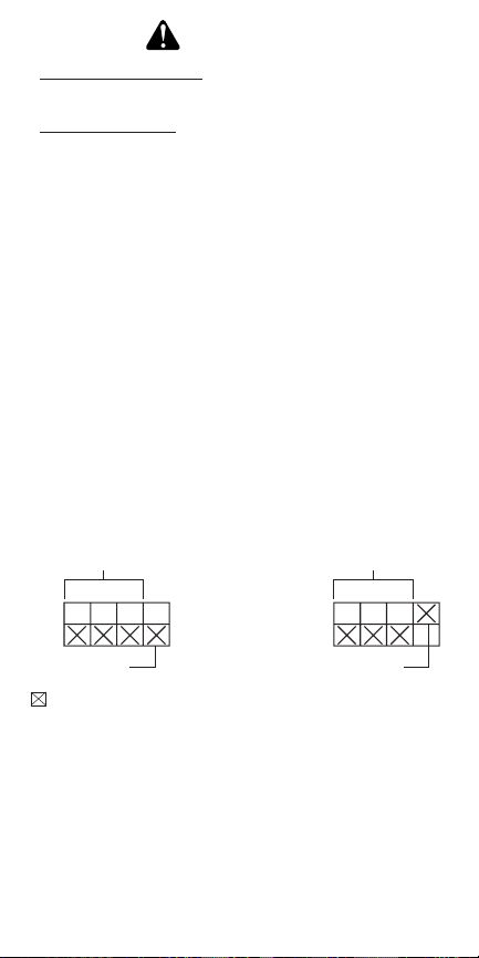
CODE SETTINGS
Note: Most single system installations will
not require any change to the code setting.
Transmitter(s) and receiver(s) must have
the same code and group setting to work
together. Switches 1 through 3 set the code.
Switch 4 sets the Group (A or B). See Code
Switch Locations for switch locations.
Example 1 - Code Switch Settings, System 1
(Factory Setting)
Transmitter(s)/
Receiver(s) Code
Group A
( – Indicates Position of Switch)
2
Transmitter(s)/
Receiver(s) Code
Group B
598-1214-03
Page 3
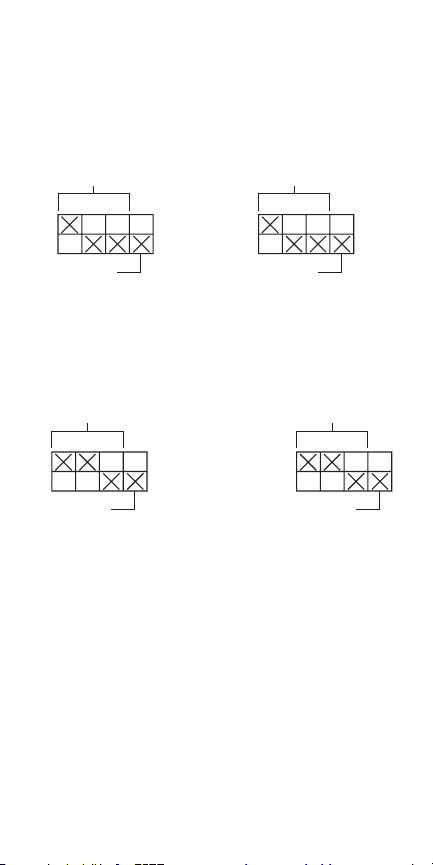
Example 2 - Code Switch Settings, System 2
Note: When operating more than one system
independently of each other, set each system to
a different code. There are 8 codes available by
changing the settings of switches 1 through 3.
Receiver(s)
Code
Transmitter(s)
Code
Group A
Group Switch
(Group A Selection Shown)
Example 3 - Code Switch Settings with Single
Transmitter
Receiver(s)
Code
Group A
Remote Motion
Sensor Code
Group A
When using the wireless motion sensor, the code
and group settings must match receiver(s) for the
system to function properly.
Note: This setting will work independently of examples 1 and 2 because the code setting is different.
Note: The channel can also be changed to reduce
interference problems from other wireless products
(i.e. wireless phones, garage door openers, etc.). See
Troubleshooting Guide for more information.
598-1214-03
3
Page 4
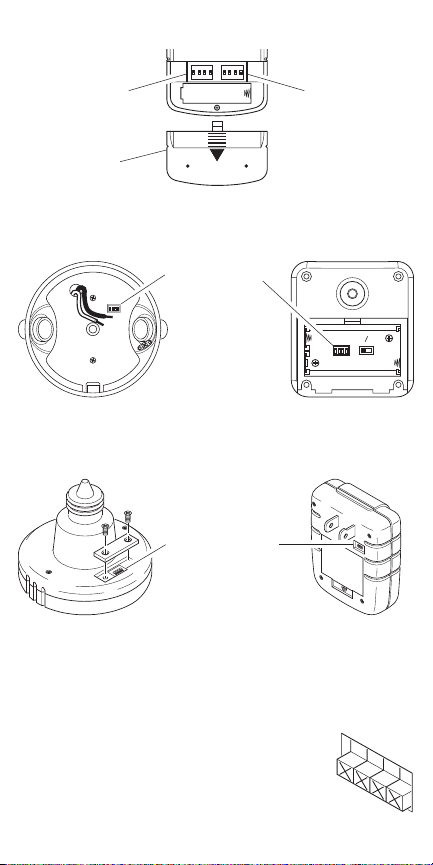
CODE SWITCH LOCATIONS
DETECT
CODES
12 3 4
DAY
NIGHT
NIGHT
ONLY
ON
1 2 3
4
1
2 3
4
O
N
1
2
3
4
ON DIP
1 2 3 4
ON DIP
1 2 3 4
Left Side Code
Switches
Battery Cover
Floodlight
Converter
Lamp Socket
Converter
Right Side
Code Switches
Remote Control
Code Switches
Wireless Motion
Sensor
Code Switches
Indoor Plug-In
Converter
Close-Up of Typical Code Switch
(Factory Default Setting is Off)
Note: The “X” has been placed on the
switches to help clarify the illustrations under Code Settings.
4
598-1214-03
Page 5
REMOTE CONTROL
ON DIP
1 2 3 4
ON DIP
1 2 3 4
One remote control is able to independently operate
two receiver units. If more than two receiver units,
operating independently, are desired, additional
remote controls will need to be purchased.
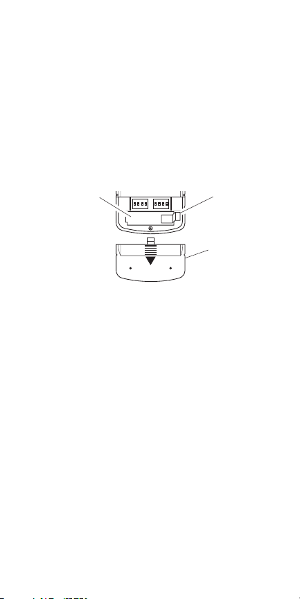
1. Remove Tab from Battery Chamber. Remove
cover from back of transmitter. Gently pull tab
out of battery chamber (see Figure 1). Slide
cover onto transmitter.
Battery Chamber
(Type A23)
Tab
Battery Cover
Figure 1 - Rear View of Remote Control
2. Remote Control Functions. The three buttons
on the left side of the remote will operate one
or more receiver units with matching code settings. The three buttons on the right side of the
remote will operate a second set of one or more
receiver units (see Figure 2).
• ON: Turns on any receiver unit set to the same
code as this remote control.
• OFF: Turns off any receiver unit set to the same
code as this remote control.
598-1214-03
5
Page 6
4 5 43
1 2 32
• DIM: Activates the DIM feature for any receiver
unit set to the same code as this remote control.
Note: Pressing the DIM button steps through
five brightness levels.
Note: To independently operate a second receiver
unit using a single remote control, make sure the
second set of code switches (Right Side) and the
code switches on each receiver match (see Code
Settings section).
• Left Side - Set left side code switches.
• Right Side - Set right side code switches.
Right Side DIM
Left Side DIM
Left Side ON
Left Side OFF
Figure 2 - Function Controls
IMPORTANT:
Wait 1 to 2 seconds after you press
Right Side ON
Right Side OFF
a transmitter button before you press it again to
allow the transmission to be completed.
Note: If light does not turn on or intermittently
turns on and off when transmitter buttons are
pushed, see Troubleshooting Guide.
6
598-1214-03
Page 7
Optional Car Visor Clip (Included)
The remote control includes an optional car visor
clip for added convenience that may be installed.
1. To attach car visor clip to remote control (if
desired) push it into slot on rear of remote unit
until it snaps into place (see Figure 3).
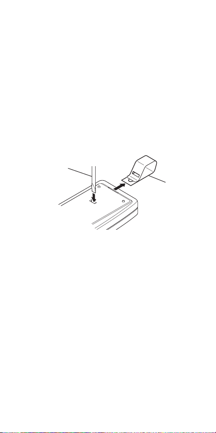
2. To remove car visor clip, insert a small, flat-
head screwdriver into slot on back of remote.
Gently push down on portion of visor clip inside
slot with screwdriver while pulling clip out of
remote from top (see Figure 3).
Flat-Head
Screwdriver
Figure 3 - Removing Visor Clip (Rear View)
Optional
Visor Clip
598-1214-03
7
Page 8
WIRELESS MOTION SENSOR
DETECT
CODES
12 3 4
DAY
NIGHT
NIGHT
ONLY
Features:
• No wiring required.
• Up to 70 feet sensing range, 180° Coverage.
• Adjustable sensitivity.
• Day/Night or Night only operation.
• Test mode.
• Uses 2 AA batteries.
• Wall or eave mount.
• Controls receivers up to 100 feet away.
Select Night or 24 Hour Mode
This sensor is able to detect motion day and night or
night only. To set the detection mode, remove rear
panel by sliding the panel down. Remove batteries
if necessary. Slide the DETECT switch to either the
DAY/NIGHT or NIGHT ONLY position. Replace
rear panel by reversing the above instructions.
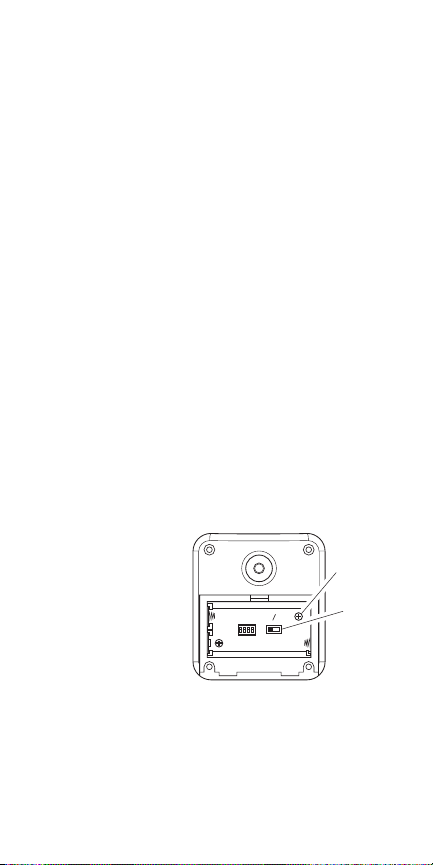
Installing Batteries
Before mounting sensor, remove rear panel by
sliding the panel down. Install 2 AA batteries
according to polarity markings inside
the battery compartment (see Figure 4).
Replace rear panel
by reversin g the
above instructions.
Figure 4 - Battery
Compartment (Rear View)
Polarity
Mark
Detect
Control
8
598-1214-03
Page 9
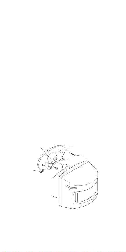
Installing Motion Sensor
1. Install sensor mounting bracket where motion
detection is desired. Attach sensor mounting
bracket to a sturdy object (i.e. tree, post, house,
etc.) using two screws provided (see Figure 5).
Make sure unit has an unobstructed view. Note:
If mounting bracket to a curved surface, attach
mounting bracket vertically.
2. Install motion sensor to mounting bracket. Us-
ing a Philips-head screwdriver, loosen the clamp
screw on the mounting bracket. Insert swivel
ball mount on sensor into mounting bracket
socket (Note: You should hear a snap). Aim
sensor toward area where detection is desired.
Tighten clamp screw (see Figure 5).
IMPORTANT: The sensor must be mounted with
the bottom cover facing down in order to maintain
water tightness.
Mounting Bracket
Socket
Clamp Screw
Swivel Ball Mount
Sensor
Figure 5 - Installing Motion Sensor
598-1214-03
Mounting Bracket
Mounting Screw
Nut
9
Page 10

Check Operation and Adjustment
5 1 TEST
ON-TI ME
(MINU TES)
RANGE
MAX
MIN
Note: When first turned on or when switching
modes wait 1 1/2 minutes.
The RANGE control and ON-TIME control are
located on the bottom of the sensor (see Figure 6).
Using your fingernails or a small, flat-head screwdriver, gently pry the cover until it opens.
1. Check Operation. Set the ON-TIME control to
TEST mode. Walk in front of sensor unit. The
LED indicator light located on the bottom of
the sensor should flash when motion is detected
(see Figure 6).
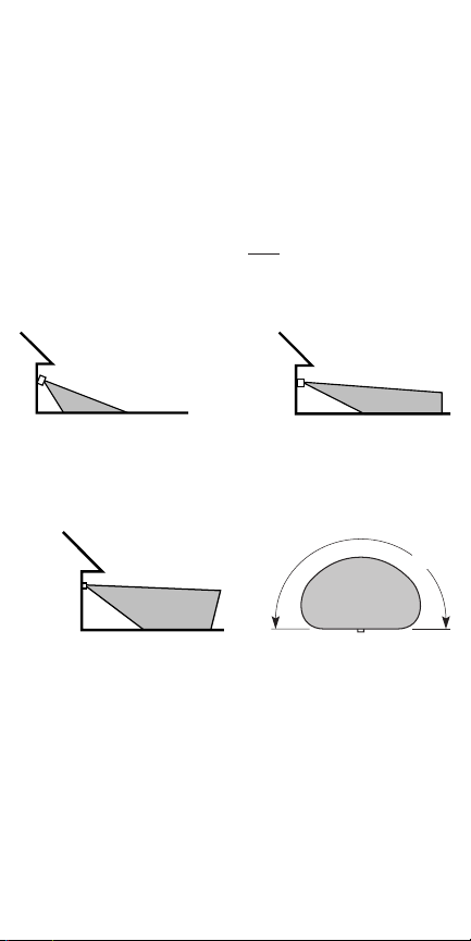
2. Adjust Sensor. Turn the RANGE control to the
mid position and ON-TIME control to the TEST
position (see Figure 6). Walk through coverage
area noting where you are when the LED begins
to flash. Loosen the clamp screw and move the
sensor to change the coverage area (see Figure
7). Tighten clamp screw when finished. Do not
overtighten clamp screw.
ON-TIME
Control
Sensitivity
Control
LED Indicator
Figure 6 - Motion Sensor Controls (Bottom View)
10
598-1214-03
Page 11
3.
Adjust Range Control. To increase sensitivity,
turn the RANGE control toward MAX. To decrease sensitivity, turn the RANGE control toward
MIN. Note: If the RANGE is set too high, false
triggering may result in some environments.
Note: When using test mode to check operation
in the day time:
A. Set the DETECT control switch to DAY/
NIGHT (see Figure 4) and
B. Set the ON-TIME control to TEST (see
Figure 6).
Aim Sensor Down
for Short Coverage
Aim Sensor Higher
for Long Coverage
Figure 7 - Adjusting Motion Sensor Coverage
180°
8 ft.
(2.4 m)
70 ft.
(21 m)
Maximum Range Maximum
Coverage Angle
Figure 8 - Coverage Area
598-1214-03
11
Page 12

4.
Set ON-TIME Control. Determine the amount of
time you want the connected device to stay on
after motion is detected (1 or 5 minutes). Slide the
ON-TIME control to the corresponding setting.
IMPORTANT: Avoid Aiming Control At:
• Objects that change temperature rapidly, such as
heating vents and air conditioners. These heat
sources could cause false triggering.
•
Areas where pets or traffic may trigger the control.
• Nearby large, light colored objects reflecting
light may trigger the shut-off feature. Do not
point other lights at the sensor.
Motion
Sensor
Least Sensitive Most Sensitive
Motion
Sensor
The detector is most sensitive to motion across its
field of view.
Figure 9 - Motion Sensor Sensitivity
12
598-1214-03
Page 13

RECEIVER INFORMATION
All receivers have the following features and ratings:
• Rated for 120VAC/60Hz supply voltage.
• Light can be dimmed when used with remote
control (OFF, 5 Selectable Dim Levels from
Dimmest to Brightest, Full On).
• Remembers last selected dim setting.
• Not for use with Compact Fluorescent bulbs.
• When first turned on wait 15 seconds.
FLOODLIGHT CONVERTER
Features and Ratings:
• Up to 150 Watt maximum incandescent load or
240 Watt maximum halogen load (up to 75 Watt
maximum incandescent, or 120 Watt maximum
halogen, per lamp holder).
• Minimal wiring required.
• Install fixture in accordance with local codes.
WARNING:
Turn power off at the fuse or
circuit breaker.
1. Remove the existing light fixture.
2.
Install the mounting strap as shown using two
screws that fit your junction box (see Figure 10).
White to White
Mounting
Strap
Junction box ground wire to
green ground screw on fixture.
Figure 10 - Wiring Floodlight Converter
598-1214-03
Black to Black
Gasket
Rubber Plug
Mounting
Bolt
13
Page 14

Note: The plastic hanger can be used to hold
the fixture while wiring. Thread the small end of
the plastic hanger through the hole in the center
of the cover plate. Insert the small end into one
of the slots on the mounting strap.
3. Route the wires from the light receiver through
the large gasket holes (see Figure 10).
4. Twist the junction box wires and fixture wires
together as shown. Secure with UL approved
wire connectors (see Figure 10).
5. Align the cover plate and cover plate gasket.
Secure with mounting bolt (see Figure 10).
6. Push the rubber plug firmly into place (see
Figure 10).
7. Not intended for waterproof junction boxes.
Fixture should be surface mount only. Caulk
the wall plate mounting surface with silicone
weather sealant.
8. Adjust the lamp holders by loosening the lock
nuts. Note: Do not rotate the lamp holders more
than 180° from the factory setting.
CAUTION: To avoid water damage and
electrical shock, keep lamp holders 30°
below horizontal.
9. Screw incandescent bulb up to rated wattage
into module. When screwing in the lamps, do
not overtighten.
14
598-1214-03
Page 15

CAUTION
: Do not exceed the maxi-
mum load limits listed above.
10. Check operation. Activate transmitter being
used with receiver (see transmitter instructions).
A signal will be sent to the receiver to turn the
receiver ON or OFF.
WARNING - Risk of fire. Do not aim
the lamps at a combustible surface within
3 ft. (1 m).
INDOOR PLUG-IN CONVERTER
Features and Ratings:
• Up to 300 Watt maximum incandescent load.
• No wiring required.
1. Plug in indoor receiver.
2. Plug in light you wish to control.
CAUTION
: Do not exceed the maxi-
mum load limits listed above.
3. Check operation. Activate transmitter being
used with receiver (see transmitter instructions).
A signal will be sent to the receiver to turn the
receiver ON or OFF.
4.
Using Remote By-Pass Switch. The receiver is
equipped with a remote by-pass switch (see Figure
11). This switch allows the user to select between
AUTO and MANUAL modes. AUTO mode allows the light to be operated by remote control
or remote motion sensor. MANUAL mode allows
the plugged in light to be operated manually.
598-1214-03
15
Page 16

5. Adjust audio alert volume. The alarm sounds
only when the receiver is activated by the wireless motion sensor and entry switch. The alarm
volume is adjusted by the thumbwheel on the
side of the receiver unit (see Figure 11).
Remote By-Pass
Switch
Speaker
Figure 11 - Control Locations
Alarm Volume
Control
LAMP SOCKET CONVERTER
Features and Ratings:
• Up to 150 Watt maximum incandescent load.
• No wiring required.
1. Screw module into light socket.
2. Screw incandescent bulb up to rated wattage
into module.
CAUTION: Do not exceed the maxi-
mum load limits listed above.
3. Check operation. Activate transmitter being used
with receiver (see transmitter instructions). A
signal will be sent to the receiver to turn the
receiver ON or OFF.
ACE® reserves the right to discontinue products
and to change specifications at any time without
incurring any obligation to incorporate new features
in products previously sold.
16
598-1214-03
Page 17

SOLUTION
1. Verify circuit breaker or fuse is turned on.
2. Change channels on transmitter and receiver
TROUBLESHOOTING GUIDE
POSSIBLE CAUSE
1. Circuit breaker or fuse is turned off.
2. Interrupted by another device.
-
units.
mote motion sensor).
3. Wait for 90 second initialization period (re
4. Check for metal objects that could block the
-
lation.
3. Does not respond immediately after instal
4. Signals from transmitter are being blocked,
signal, or reposition the transmitter.
Check battery charge and replace if necessary.
receiver units are set the same.
5.
6. Verify dip switch settings on transmitter and
7. Test using different device.
or transmitter is out of range.
units do not match.
5. Weak battery in the transmitter.
6. Dip switches on transmitter and receiver
7. Device is defective.
receiver to correct state.
1. Same as 4, 5, and 6 above.
1. Next transmission from transmitter will reset
1. Same as 4, 5, and 6 above.
1. Short term power line failure.
2. Change channels on transmitter and receiver
units.
2. Another transmitter on the same channel.
SYMPTOM
598-1214-03
Device does not come on.
Device does not turn off.
Device comes on randomly.
17
Page 18

TECHNICAL SERVICE
Please call 1-800-858-8501 for assistance
before returning product to store.
If you experience a problem, follow this guide.
You may also want to visit our Web site at: www.
hzsupport.com. If the problem persists, call* for
assistance at 1-800-858-8501, 7:30 AM to 4:30
PM CST (M-F). You may also write* to:
HeathCo LLC
ATTN: Technical Service
P.O. Box 90004, Bowling Green, KY 42102-9004
* If contacting Technical Service, please have the
following information available: Model Number,
Date of Purchase, and Place of Purchase.
No Service Parts Available for these
Products
REGULATORY INFORMATION
This device complies with Part 15 of the FCC Rules
and RSS-210 of Industry Canada. Operation is subject
to the following two conditions: (1) this device may
not cause harmful interference, and (2) this device
must accept any interference received, including
interference that may cause undesired operation.
The user is cautioned that changes or modifications
not expressly approved by the party responsible
for regulatory compliance could void the user’s
authority to operate the equipment.
18
598-1214-03
Page 19

PRoduCtos
a ContRol
Remoto
Control remoto
enchufable para
usarse bajo techo
Detector
inalámbrico de
movimiento
Convertidor
del zócalo de
Convertidor
del Faro
Convertidor
la lámpara
Este manual incluye instrucciones de funcionamiento
para los productos a control remoto que se muestran
arriba. Todos los productos funcionan basándose en el
mismo principio y usan la misma información para la
calibración del código. Por favor lea todas las instrucciones y tome en cuenta cualquier información específica
relativa a su producto en particular.
CARACTERISTICAS
• Productos probados y aprobados por laboratorios
UL/cUL y/o FCC/IC.
• Distancia de operación: hasta 100 pies.
Los controles inalámbricos ACE® para el alumbrado
están diseñados para trabajar juntos. Simplemente
determine cual transmisor(es) le gustaría que controlen tal(es) receptor(es) y fije la calibración del código
para emparejar.
598-1214-03
© 2007 598-1214-03 S
19
Page 20

ADVERTENCIAS:
• PARA USO SÓLO con bombillas incandes-
centes o halógenas de 120 voltios.
• NO LO USE con bombillas fluorescentes,
electrodomésticos, fuentes de energía, alumbrado con bajo voltaje ni con ningún otro
aparato eléctrico.
CALIBRACIONES DEL CÓDIGO
Nota: La mayoría de instalaciones de sólo un
sistema no requerirán ningún cambio en la calibración del código. Para que funcionen juntos
los transmisor(es) y los receptor(es) deben tener
la misma calibración de código y de grupo. Los
interruptores del 1 al 3 fijan el código. El interruptor 4 fija el grupo (A o B). Vea las Ubicaciones
de los interruptores de circuito impreso para las
ubicaciones de los interruptores.
Ejemplo 1- Calibraciones del interruptor del
código, sistema 1 (calibración de fábrica)
Código del(de los)
transmisor(es)/
receptor(es)
Grupo “A”
( – Indica la posición del interruptor)
20
Código del(de los)
transmisor(es)/
receptor(es)
Grupo “B”
598-1214-03
Page 21

Ejemplo 2- Calibraciones del interruptor del
código, sistema 2
Nota: Cuando opere más de un sistema independientemente el uno del otro, fije cada sistema con un código
diferente. Hay 8 códigos disponibles al cambiar las
calibraciones de los interruptores del 1 al 3.
Código del
receptor(es)
Grupo “A”
Código del (de los)
transmisor(es)
Interruptor del grupo
(Grupo A Selección mostrada)
Ejemplo 3 - Calibraciones del interruptor del
código con un sólo transmisor
Código del
receptor(es)
Grupo “A”
Código del
detector remoto
de movimiento
Grupo “A”
Cuando se use el detector inalámbrico de movimiento,
las calibraciones del código y del grupo deben emparejar
con el(los) receptor(es) para que el sistema funcione
correctamente.
Nota: Esta calibración funcionará independientemente
de los ejemplos uno y dos porque la calibración del
código es diferente.
Nota: También puede cambiarse el canal para reducir
problemas de interferencia que vienen de otros productos
inalámbricos (ejemplo: Teléfonos inalámbricos, abridores de puertas de garajes, etc.) Para más información vea
Guía de Análisis de Averías.
598-1214-03
21
Page 22

ON DIP
1 2 3 4
ON DIP
1 2 3 4
DETECT
CODES
12 3 4
DAY
NIGHT
NIGHT
ONLY
UBICACIONES DE LOS
1
2 3
4
O
N
1
2
3
4
ON
1 2 3
4
INTERRUPTORES DE CIRCUITO
IMPRESO
Interruptores
de código del
lado izquierdo
Tapa de la
batería
Control remoto
Interruptores de
circuito impreso
Convertidor del
Faro
Interruptores de
circuito impreso
Convertidor
del zócalo
de la lámpara
enchufable para
usarse bajo techo
Vista ampliada de un interruptor
típico del código (la calibración hecha en fábrica es OFF- apagado)
Nota: Se ha colocado la “X” en los interruptores para clarificar las ilustraciones
bajo Calibraciones de código.
22
Interruptores
de código del
lado derecho
Detector
inalámbrico de
movimiento
Convertidor
598-1214-03
Page 23

ON DIP
1 2 3 4
ON DIP
1 2 3 4
CONTROL REMOTO
Un control remoto puede operar independientemente dos
unidades receptoras. Si se desea operar independientemente más de dos receptores, se necesitarán comprar
controles remotos adicionales.
1. Retire la aleta del compartimento de la batería. Retire
la tapa posterior del transmisor. Hale la aleta con
suavidad fuera del compartimento de la batería (vea
Figura 1). Deslice la tapa en el transmisor.
Compartimento
Aleta
de la batería
(tipo A23)
Tapa de la batería
Figura 1 - Vista posterior del control remoto
2. Funciones del control remoto. Los tres botones del lado
izquierdo del control remoto hacen funcionar a una o
más unidades receptoras que tienen la misma calibración del código. Los tres botones de la derecha harán
funcionar un segundo juego de uno o más receptores
(vea Figura 2).
• ON: Enciende cualquier unidad receptora del mismo
código que este control remoto.
• OFF:
Apaga cualquier unidad receptora del mismo
código que este control remoto.
598-1214-03
23
Page 24

4 5 43
1 2 32
• DIM: Activa la característica REDUCTORA de cual-
quier unidad receptora del mismo código que este
control remoto. Nota: Al pulsar el botón DIM se pasa
por los cinco niveles de luminosidad.
Nota: Para operar independientemente una segunda
unidad receptora usando un único control remoto, asegúrese que el segundo juego de interruptores de código
(del lado derecho) emparejen con los interruptores de
código de cada receptor (Ver la sección Calibraciones
del Código).
• Lado izquierdo - Para calibrar los interruptores de
código del lado izquierdo.
• Lado derecho - Para calibrar los interruptores de
código del lado derecho.
Lado derecho
Lado izquierdo
DIM
Lado izquierdo
(ON)ENCENDIDO
Lado izquierdo
(OFF)APAGADO
DIM
Lado derecho
(ON)ENCENDIDO
Lado derecho
(OFF)APAGADO
Figura 2 - Controles de las funciones
IMPORTANTE: Espere de 1 a 2 segundos después de
pulsar el botón de un transmisor antes de pulsarlo de
nuevo para permitir que la transmisión se complete.
Nota: Si la luz no se prende o si se prende y apaga
intermitentemente cuando se pulsan los botones del
transmisor, vea la Guía de Análisis de Averías.
24
598-1214-03
Page 25

Presilla opcional del visor del carro (incluida)
Para mayor conveniencia, en el control remoto se incluye
una presilla opcional del visor del carro que puede ser
instalada.
1. Para unir (si se desea) la presilla del visor del carro al
control remoto empújela contra la ranura de la parte
posterior del control hasta que se cierre a presión en
su lugar (vea Figura 3).
2. Para retirar esta presilla, inserte un destornillador
plano pequeño en la ranura de la parte posterior del
control. Con el destornillador, empuje suavemente
la porción de la presilla del visor que está dentro de
la ranura mientras desde arriba hala la presilla hacia
fuera del control (vea Figura 3).
Destornillador
plano
Figura 3 - Retiro de la presilla del visor (Vista posterior)
Presilla
opcional
del visor
598-1214-03
25
Page 26

DETECTOR INALÁMBRICO
DE MOVIMIENTO
Características:
• No se requiere cableado.
• Margen de sensibilidad hasta 70 pies. 180° de cober-
tura.
• Sensibilidad ajustable.
• Operación diurna/nocturna o sólo nocturna.
• Modo prueba.
• Usa dos baterías AA.
• Montaje en pared o alero.
• Controla los receptores hasta 100 pies de distancia.
Seleccione modo nocturno o modo de 24
horas
Este detector es capaz de detectar movimiento de día y de
noche o sólo de noche. Para fijar el modo de detección,
retire el panel posterior deslizándolo hacia abajo. Si es
necesario retire las baterías. Mueva el interruptor DETECT (DETECTAR) ya sea a la posición DAY/NIGHT
ó a la posición ONLY NIGHT (SÓLO NOCHE). Vuelva
a colocar el panel posterior siguiendo en orden inverso
las instrucciones anteriores.
26
598-1214-03
Page 27

DETECT
CODES
12 3 4
DAY
NIGHT
NIGHT
ONLY
Instalación de las baterías
Antes de instalar el detector retire el panel posterior deslizándolo hacia abajo. Coloque las dos baterías AA según
la polaridad marcada
dentro del compartimento de la batería (vea
Figura 4). Vuelva a colocar el panel posterior
siguiendo en orden in-
Marca de
polaridad
Control
detector
verso las instrucciones
anteriores.
Figura 4 - Compartimento de
la batería (Vista posterior)
Instalación del detector de movimiento
1. Instale la consola de montaje del detector en donde
se necesite detectar movimiento. Acople esta consola
de montaje a un objeto robusto (ejemplo: árbol, poste,
casa, etc.) usando los dos tornillos provistos (vea Figura 5). Asegúrese que la unidad no tenga obstrucciones
en su línea de mira. Nota: Si monta la consola a una
superficie curva, acóplela verticalmente.
Zócalo de la consola
de montaje
Consola de montaje
Tornillo de montaje
Tornillo de la
abrazadera
Tuerca
Montura giratoria de bola
Detector
Figura 5 - Instalación del detector de movimiento
598-1214-03
27
Page 28

2. Instale el detector de movimiento a la consola de
5 1 TEST
ON-TI ME
(MINU TES)
RANGE
MAX
MIN
montaje. Usando un destornillador cabeza Philips,
afloje el tornillo de la abrazadera en la consola de
montaje. Inserte la montura giratoria de bola del
detector en el zócalo de la consola de montaje (Nota:
Usted debería oír un chasquido -un clic-). Apunte el
detector hacia el área que se requiere detectar. Apriete
el tornillo de la abrazadera (vea Figura 5).
IMPORTANTE:
El detector debe estar montado con
la tapa inferior hacia abajo con el fin de mantener la
hermeticidad contra el agua.
Revisión de la operación y de la regulación
Nota: Cuando lo prenda por primera vez o cuando cambie de modalidad espere 1 1/2 minutos.
Los controles de ALCANCE y DURACIÓN están
ubicados en la parte inferior del detector (vea Figura
6). Usando las uñas de los dedos o un destornillador
pequeño de cabeza plana, haga suavemente palanca en
la tapa hasta que se abra.
1. Revise la operación.
en el modo TEST (PRUEBA). Camine frente a la unidad detectora. Cuando un movimiento es detectado,
la luz indicadora LED ubicada en la parte inferior del
detector debería destellar (vea Figura 6).
Control de
DURACIÓN
Ponga el control de DURACIÓN
Control de la
sensibilidad
Indicador LED
Figura 6 - Controles del detector de movimiento
28
(Vista inferior)
598-1214-03
Page 29

2. Regule el detector. Gire el control de ALCANCE a
la posición media y el de DURACIÓN a la posición
TEST (vea Figura 6). Camine por el área de cobertura
y note su posición cuando el LED empiece a destellar.
Afloje el tornillo de la abrazadera y mueva el detector
para cambiar el área de cobertura. Cuando termine
apriete el tornillo de la abrazadera (vea Figura 7).
No apriete excesivamente este tornillo.
3.
Regule el control de alcance. Para incrementar la sen-
sibilidad, gire el control de ALCANCE hacia MAX.
Para disminuir la sensibilidad, gírelo hacia MIN. Nota:
En algunos ambientes si el ALCANCE se calibra
demasiado alto, puede ocurrir una falsa activación.
Nota: Cuando use el modo de prueba (Test) para
comprobar el funcionamiento durante el día:
A.
Ponga el interruptor del control DETECT (DETEC-
TAR) a DAY/NIGHT (NOCHE/DÍA) (vea Figura 1) y
B. Ponga el control ON-TIME (DURACIÓN) a
TEST (vea Figura 6).
Apunte el detector
hacia abajo para
una cobertura
menor
Apunte el detector
hacia más arriba
para una cobertura
mayor
Figura 7 - Regulación de la cobertura del detector de
movimiento
2.4 m
21 m
Alcance máximo Ángulo máximo
de cobertura
180°
Figura 8 - Área de cobertura
598-1214-03
29
Page 30

4. Fije el control de DURACIÓN. Determine la
cantidad de tiempo que desea que el dispositivo conectado permanezca encendido luego que se detecta
movimiento (1 ó 5 minutos). Mueva el control de
DURACIÓN a la configuración correspondiente.
IMPORTANTE:
Evite apuntar el control:
• A objetos que cambian rápidamente de temperatura,
tales como ventosas de calor y acondicionadores de
aire. Estas fuentes de calor podrían ocasionar una
activación falsa.
• A áreas en donde las mascotas o el tráfico pueden
activar el control.
• En las cercanías de objetos grandes pintados con
colores claros cuyo reflejo puede activar el apagado.
No enfoque otras luces al detector.
Movimiento
Detector
Sensibilidad mínima Sensibilidad máxima
Movimiento
Detector
El detector es más sensible a movimientos transversales
a su campo de mira.
Figura 9 - Sensibilidad del detector de movimiento
30
598-1214-03
Page 31

INFORMACIÓN DEL RECEPTOR
Todos los receptores tienen las siguientes características
y potencias nominales:
• Clasificado para un voltaje de alimentación de 120 V
CA/60Hz.
• La luz puede reducirse cuando se lo usa con control
remoto (APAGADO, 4 niveles de reducción a elegir
desde el más apagado al más brillante).
• Recordatorios de las últimas calibraciones de reduc-
ción seleccionadas.
• No se los usa con bombillas fluorescentes compactas.
•
Cuando lo prenda por primera vez, espere 15 segundos.
CONVERTIDOR DEL FARO
Características y potencias nominales:
• Hasta una carga incandescente máxima de 150 vatios
o una carga
halógena máxima de 240 vatios (hasta 75 vatios
máximo de incandescente, o 120 vatios máximo de
halógena por cada portalámparas).
• Se requiere un cableado mínimo.
• Instale el aparato de acuerdo a los códigos locales.
ADVERTENCIA: Desconecte la alimentación
en el fusible o en el disyuntor.
1. Retire el aparato de luz existente.
2. Como se muestra, instale la lámina de montaje usan
do dos tornillos que encajen en su caja de empalme
(vea Figura 10).
Nota: Puede usarse un colgador plástico para sostener
el aparato mientras se cablea. Enrosque el extremo
pequeño del colgador plástico en el orificio central
de la placa cubertora. Inserte el extremo pequeño en
una de las ranuras de la lámina de montaje.
3. Guíe los cables desde el receptor para lámpara pasando
por el orificio grande del empaque (vea Figura 10).
-
598-1214-03
31
Page 32

Blanco con blanco
Lámina de
montaje
Conductor de tierra de la caja de empalme
al tornillo verde de tierra en el aparato.
Negro con negro
Tapón de caucho
Empaque
Perno de
montaje
Figura 10 - Conexión del Convertidor del Faro
4. Tuerza juntos, como se muestra, los cables de la caja
de empalme con los del aparato. Asegúrelos con
conectores de alambre que tengan aprobación UL
(vea Figura 10).
5. Alinee la placa cubertora con su empaque. Asegúre
los con el perno de montaje (vea Figura 10).
6. Empuje firmemente el tapón de caucho hasta su sitio
(vea Figura 10).
7. No se lo debe usar con cajas de empalme impermea
bles. Al aparato se lo debe instalar sólo sobre una superficie. Calafatee la superficie de montaje de la placa
con un sellador de silicona contra la intemperie.
8. Regule los portalámparas aflojando las contratuercas.
Nota: No gire los portalámparas más de 180° de la
calibración de fábrica.
PRECAUCIÓN: Para evitar daño por agua
y sacudida eléctrica mantenga los portalámparas a 30° por debajo de la horizontal.
9. Enrosque en el módulo una bombilla incandescente
cuya potencia sea hasta la nominal. Cuando la enrosque en la lámpara no la apriete excesivamente.
PRECAUCIÓN: No exceda los límites de
carga máximos indicados arriba.
32
598-1214-03
-
-
Page 33

10. Revise la operación. Active el transmisor que va
a usarse con el receptor (vea las instrucciones del
transmisor). Una señal será enviada al receptor para
ENCENDERLO o APAGARLO.
ADVERTENCIA - Riesgo de incendio. No
apunte las lámparas a superficies combustibles dentro de un 1 metro.
CONVERTIDOR ENCHUFABLE PARA
USARSE BAJO TECHO
Características y potencias nominales:
• Carga incandescente máxima hasta 300 vatios.
• No se requiere cableado.
1. Enchufe el receptor para interiores.
2. Enchufe la lámpara que desea controlar.
PRECAUCIÓN: No exceda el límite de
carga máxima indicada arriba.
3. Revise la operación. Active el transmisor que va
a usarse con el receptor (vea las instrucciones del
transmisor). Una señal será enviada al receptor para
ENCENDERLO o APAGARLO.
Interruptor
derivante
remoto
Parlante
Figura 11 - Ubicación de los controles
598-1214-03
Control del
volumen de la
alarma
33
Page 34

4. Uso del interruptor derivante remoto. El receptor está
equipado con un interruptor derivante (vea Figura
11). Este interruptor permite al usuario seleccionar
entre los modos AUTOMÁTICO y MANUAL. El
modo AUTOMÁTICO permite operar a la lámpara
con el control remoto o con el detector remoto de
movimiento. El modo MANUAL permite que la
lámpara enchufada opere manualmente.
5. Regulación del volumen de la alarma sonora. La alar
ma suena solamente cuando el receptor es activado
por el detector remoto de movimiento y interruptor
de entrada. El volumen de la alarma se regula usando
la ruedecilla lateral del receptor (vea Figura 11).
CONVERTIDOR DEL ZÓCALO DE LA
LÁMPARA
Características y potencias nominales:
• Carga incandescente máxima hasta 150 vatios.
• No se necesita cableado.
1. Enrosque el módulo en el zócalo de la lámpara.
2. Enrosque en el módulo una bombilla incandescente
cuya potencia sea hasta la nominal.
PRECAUCIÓN: No exceda los límites
máximos de carga indicados arriba.
3. Revise la operación. Active el transmisor que va
a usarse con el receptor (vea las instrucciones del
transmisor). Una señal será enviada al receptor para
ENCENDERLO o APAGARLO.
-
ACE® se reserva el derecho de descontinuar productos y
de cambiar especificaciones, cuando desee, sin incurrir
en ninguna obligación de incorporar las nuevas características en los productos vendidos anteriormente.
34
598-1214-03
Page 35

-
tores.
(detector remoto de movimiento).
señal, o vuelva a poner el transmisor en posición.
sario.
de circuito impreso tanto en el transmisor como en
SOLUCIÓN
1. Verifique que el disyuntor o el fusible esté conectado.
2. Cambie los canales en el transmisor y en los recep
3. Espere los 90 segundos del período de iniciación
4. Revise objetos metálicos que podrían bloquear la
-
5. Revise la carga de la batería y reemplace si es nece-
los receptores sean iguales.
6. Verifique que la configuración de los interruptores
-
figurará al receptor a su estado correcto.
1. La siguiente transmisión desde el transmisor recon
-
tores.
2. Cambie los canales en el transmisor y en los recep-
7. Pruebe usando un dispositivo diferente.
1. Igual que el 4, 5 y 6 anteriores.
GUÍA DE ANÁLISIS DE AVERÍAS
CAUSA PROBABLE
SÍNTOMA
598-1214-03
lación.
3. No responde inmediatamente luego de la insta
queadas o el transmisor está fuera de alcance.
4. Las señales desde el transmisor están siendo blo-
1. El disyuntor o el fusible está desconectado.
2. Interrumpido por otro dispositivo.
El dispositivo no se enciende.
transmisor y los receptores no emparejan.
5. Batería desgastada en el transmisor.
6. Los interruptores de circuito impreso en el
7. El dispositivo está defectuoso.
1. Igual que el 4, 5 y 6 anteriores.
El dispositivo no se apaga.
ción.
1. Falla de corta duración en la línea de alimenta
2. Hay otro transmisor en el mismo canal.
El dispositivo se enciende al
azar.
35
Page 36

SERVICIO TÉCNICO
Favor de llamar al 1-800-858-8501 (sólo
para hablar en inglés) para pedir ayuda
antes de devolver el producto a la tienda.
Si tiene algún problema, siga esta guía. Usted puede
también visitar nuestro sitio Web: www.hzsupport.
com. Si el problema continúa, llame al 1-800-8588501 (sólo para hablar en inglés), de 7:30 AM a 4:30
PM CST (L-V). Usted puede también escribir a:
HeathCo LLC
P.O. Box 90004
Bowling Green, KY 42102-9004
ATTN: Technical Service (Servicio Técnic)
* Si se llama al Servicio Técnico, por favor tener lista
la siguiente información: Número de Modelo, Fecha de
compra y Lugar de compra.
No hay piezas de servicio disponibles
para este producto.
INFORMACIÓN REGULATORIA
Este aparato cumple con la Parte 15 de las Reglas de
la FCC (Comisión Federal de Comunicaciones) y con
la RSS-210 de las Industrias del Canadá. El funcionamiento está sujeto a las dos siguientes condiciones: (1)
este aparato no puede causar interferencias dañinas, y
(2) este aparato debe aceptar cualquier interferencia
recibida, incluyendo una interferencia que pueda causar
un funcionamiento indeseable.
Se advierte al usuario que cambios o modificaciones
no aprobadas expresamente por la parte responsable de
cumplir con los reglamentos podría invalidar la autoridad
del usuario para el uso de este equipo.
36
598-1214-03
 Loading...