

Page 1
Remote Controlled Products
DIM
ON
OFF
ON
OFF
DIM
This manual includes operating instructions for a variety of remote controlled products. All products work on the same principle and use the same
code setting information. Please read all instructional information and note any specific information pertaining to your particular product.
This manual applies to the following products:
• Transmitters
– Remote Control
– Indoor Wireless Motion Sensor
– Outdoor Wireless Motion Sensor
– Add-A-Switch
– Kid’s Remote Control
– 3-Way Wall Switch
• Receivers
– Wall Switch Receiver
– Receptacle Receiver
• Products are UL/cUL and/or FCC/IC tested and approved.
• Operational range of up to 100 feet.
Heath®/Zenith wireless lighting controls are designed to
work together. Simply determine which transmitter(s) you
would like to have control which receiver(s) and set the code
setting to match.
FEATURES
ENGLISH
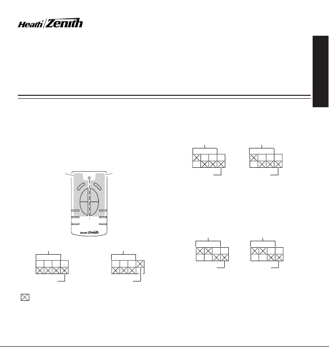
Note: Most single system installations will not require any
change to the code setting. Transmitter(s) and receiver(s)
must have the same code and group setting to work together.
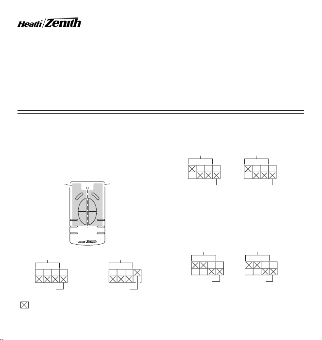
Switches 1 through 3 set the code. Switch 4 sets the Group (A
or B). See page 2 for switch locations.
Left Side Controls:
Controls One Set of
Group “A” or Group
“B” Receiver(s)
( – Indicates Position of Switch)
CODE SETTINGS
Example 1 - Code Settings, System 1
Transmitter(s)/
Receiver(s) Code
Group “A”
(Factory Setting)
Right Side Controls:
Controls One Set of
Group “A” or Group
“B” Receiver(s)
Transmitter(s)/
Receiver(s) Code
Group “B”
Example 2 - Code Settings, System 2
Note: When operating more than one system independently of each
other, set each system to a different code. There are 8 codes available by changing the settings of switches 1 through 3.
Receiver(s)
Code
Group “A”
Example 3 - Code Settings with Single Transmitter
When using a single group transmitter (i.e. Door Transmitter, Add-ASwitch, Remote Motion Sensor) the code and group settings must
match receiver(s) for the system to function properly.
Receiver(s)
Code
Group “A”
Note: This setting will work independently of examples 1 and 2
because the code setting is different.
Note: The code can also be changed to reduce interference problems
from other wireless products (i.e. wireless phones, garage door openers, etc.). See Troubleshooting Guide for more information.
Transmitter
Code
Group Switch
(Group “A” Selection Shown)
Remote Motion
Sensor Code
Group “A”
© 2007 HeathCo LLC 598-1135-08
Page 2
1 2 3 4
ON
2032
3
V
L
i
t
h
i
u
m
B
a
t
t
e
r
y
DIM
1 2 3 4
ON
DETECT
CODES
12 34
DAY
NIGHT
NIGHT
ONLY
ON
12V
C
O
N
T
R
O
L
L
E
D
O
N
1
2 3
4
ON
DIM
ON
1 2 3
4
ON
ON DIP
1 2 3 4
ON DIP
1 2 3 4
Left Side
CODE
1 2 3 4
ON
5 1 TEST
ON-TIME
(MINUTES)
MIN MAX
DETECT
RANGE
DAY
NIGHT
NIGHT
ONLY
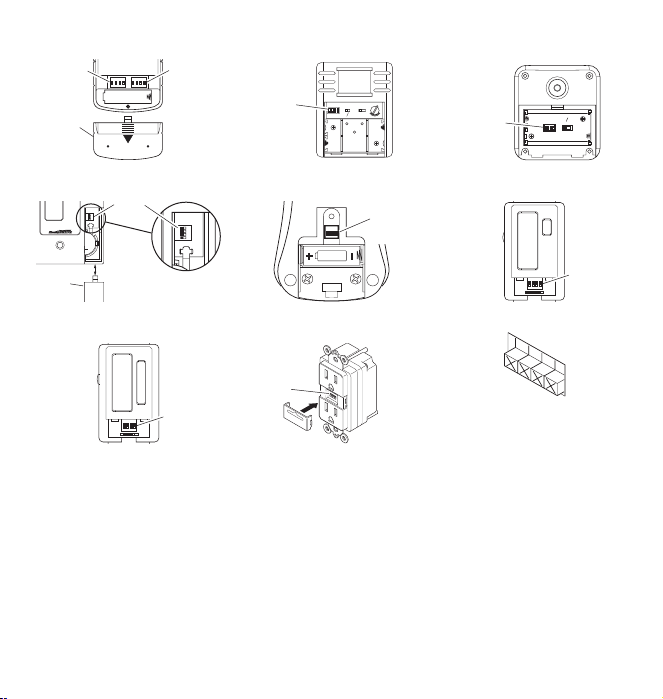
Code
Switches
Battery
Cover
Remote Control
Code
Switches
Right Side
Code
Switches
CODE SWITCH LOCATIONS
Code
Switches
Indoor Wireless Motion Sensor
Code
Switches
Code
Switches
Outdoor Wireless Motion Sensor
Access
Door
Add-A-Switch
Wall Switch Receiver
Code
Switches
Kid’s Remote Control
Code
Switches
Receptacle Receiver
Code
Switches
3-Way Wall Switch Transmitter
Note: The “X” has been placed on the
switches to help clarify the code settings
on the previous page.
Close-Up of Typical Code Switch
(Factory Default Setting is Off)
2 598-1135-08
Page 3
REMOTE CONTROL
4 5 43
1 2 32
ON DIP
1 2 3 4
ON DIP
1 2 3 4
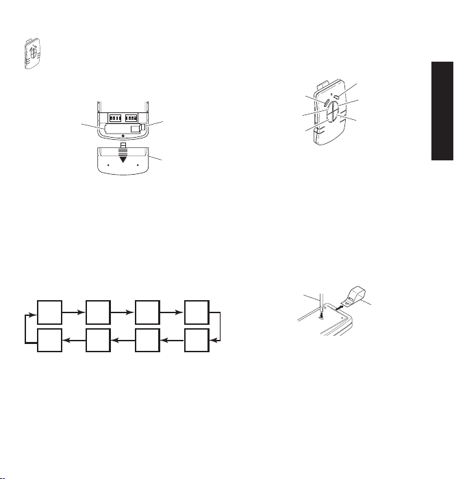
Note: One remote control is able to independently operate
two receiver units. If more than two receiver units, operating
independently, are desired, additional remote controls will
need to be purchased.
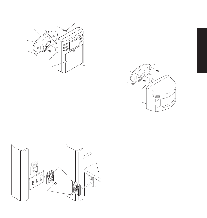
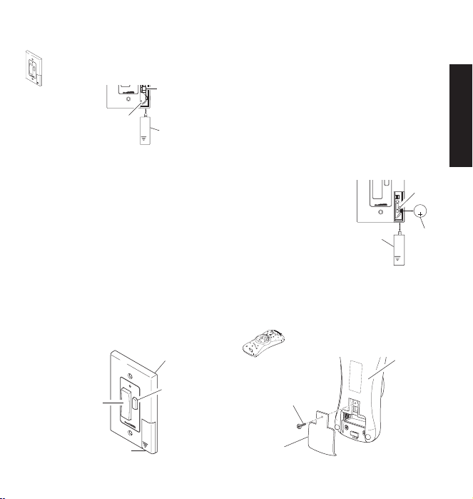
1. Remove Tab from Battery Chamber. Remove cover
from back of transmitter. Gently pull tab out of battery chamber.
Slide cover onto transmitter.
Battery Chamber
(Type A23)
2. Remote Control Functions. The three buttons on the left side
• ON: Turns on any receiver unit set to the same code as this
remote control.
• OFF: Turns off any receiver unit set to the same code as this
remote control.
• DIM: Activates the DIM feature for any receiver unit set to the
same code as this remote control. Note: Pressing the DIM button
steps through five brightness levels.
Rear View of Remote Control
of the remote will operate one or more receiver units with
matching code settings. The three buttons on the right side of
the remote will operate a second set of one or more receiver
units.
Tab
Battery
Cover
Note: To independently operate a second receiver unit using a
single remote control, make sure the second set of code switches
(Right Side) and the code switches on each receiver match (see
Code Settings section).
• Left Side - Set left side code switches.
• Right Side - Set right side code switches.
Left Side DIM
Left Side ON
Left Side OFF
IMPORTANT: Wait 1 to 2 seconds after you press a transmitter
button before you press it again to allow the transmission to be
completed.
Note: If light does not turn on or intermittently turns on and off when
transmitter buttons are pushed, see Troubleshooting Guide.
The remote control includes an optional car visor clip for added
convenience that may be installed.
1. To attach car visor clip to remote control (if desired) push it
into slot on rear of remote unit until it snaps into place.
2. To remove car visor clip, insert a small, flat-head screwdriver
into slot on back of remote. Gently push down on portion of
visor clip inside slot with screwdriver while pulling clip out of
remote from top.
3598-1135-08
Function Controls
Optional Car Visor Clip (Included)
Flat-Head
Screwdriver
Removing Visor Clip - Rear View
Right Side DIM
Right Side ON
Right Side OFF
Optional
Visor Clip
ENGLISH
Page 4
DETECT
CODES
12 3 4
DAY
NIGHT
NIGHT
ONLY
INDOOR AND OUTDOOR
O
N
Da
y
/ Ni
g
h
t
N
ight
O
nl
y
5
1
Te
st
Ma
x
Mi
n
CODE
1 2 3 4
ON
5 1 TEST
ON-TIME
(MINUTES)
MIN MAX
DETECT
RANGE
DAY
NIGHT
NIGHT
ONLY
WIRELESS MOTION SENSOR
Features:
• No wiring required.
• Up to 70 feet sensing range, 180° Coverage
(Outdoor).
• Up to 30 feet sensing range, 150° Coverage
(Indoor).
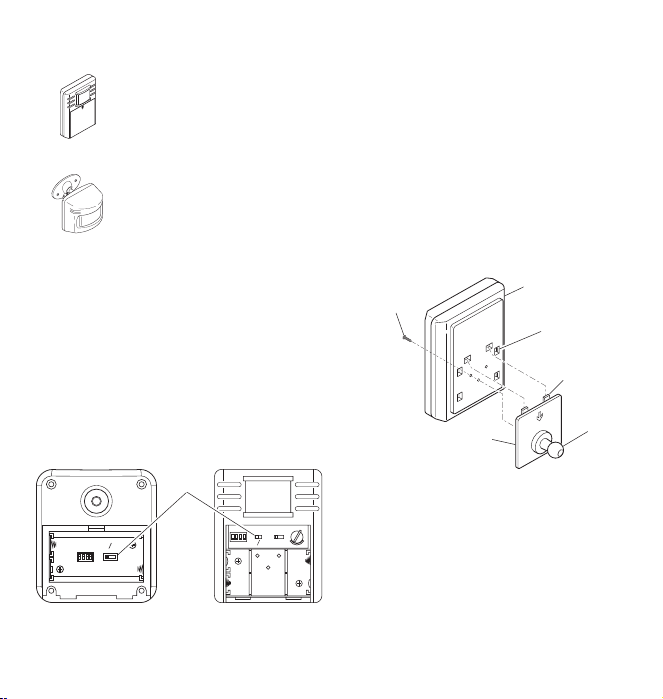
Indoor Wireless
Motion Sensor
Outdoor Wireless
Motion Sensor
These sensors are able to detect motion day and night or night
only. To set the detection mode, remove battery compartment
cover by sliding the cover down. Remove batteries if necessary.
Slide the DETECT switch to either the DAY/NIGHT or NIGHT
ONLY position. Replace battery compartment cover by reversing
the above instructions.
• Before mounting outdoor motion sensor, remove battery compartment cover by sliding the cover down.
• For indoor motion sensor, install batteries after sensor is installed.
Install 2 AA batteries according to polarity markings inside the
battery compartment. Replace battery compartment cover by
reversing the above instructions.
Outdoor Motion Sensor
• Adjustable sensitivity.
• Day/Night or Night only operation.
• Test mode.
• Uses 2 AA batteries.
• Wall or eave mount (Outdoor).
• Can be mounted directly to wall or with
mounting bracket (included) (Indoor).
• Controls receivers up to 100 feet away.
Select Night or 24 Hour Mode
Installing Batteries
Detect
Control
(Rear View)
Battery Compartment
Indoor Motion Sensor
(Front View)
Installing Indoor Motion Sensor Using Optional
Note: Mount the indoor motion sensor so that it can be angled up or
down to give you the desired coverage above the floor level.
1. Attach ball mounting bracket to rear of motion sensor. The ball
mounting bracket is designed to mount to the rear of the sensor
in three possible directions depending upon the installation
requirements. To attach the ball mounting bracket, follow the
steps shown below:
• Determine the best mounting position of the sensor for the
coverage desired.
• Determine the best location of the wall mounting bracket.
• Insert the tabs on the ball mounting bracket into the tab slots
on the rear of the sensor that best align the sensor with the
wall mounting bracket.
• Remove the batteries.
• Using a philips-head screwdriver, insert mounting screw into
the hole in the battery compartment that aligns with the hole
on the rear of the ball mounting bracket. Tighten securely.
Ball Mounting
Bracket Screw
Mounting Bracket
Rear of Sensor
Tab Slots
Tab
Ball Mounting
Bracket
Attaching Ball Mounting Bracket to Indoor Motion Sensor
2. Place sensor mounting bracket against surface to be mounted
3. Using a 2.5 mm (0.1") drill bit, drill two pilot holes for mounting
4. Attach indoor motion sensor mounting bracket to a sturdy object
5. Install motion sensor to mounting bracket. Using a Philips-head
4 598-1135-08
(Vertical Installation Shown)
on and mark hole locations with pencil or center punch.
screws. If not mounting directly to wood or wood stud, drill 5
mm (0.2") pilot holes and use the included wall anchors.
(i.e. wall, ceiling, post, etc.) using two screws provided. Make
sure unit has an unobstructed view. Note: Attach mounting
bracket vertically if connecting to a curved surface such as a
post.
screwdriver, loosen the clamp screw on the mounting bracket.
Insert swivel ball mount on sensor into mounting bracket socket
Swivel
Ball
Mount
Page 5
(Note: You should hear a snap). Aim sensor toward area where
O
N
D
ay
/
N
ight
Night
Only
5 1
Te
s
t
M
ax
M
in
O
N
D
ay
/
N
ig
h
t
N
ig
ht
On
l
y
5
1
T
es
t
M
a
x
Mi
n
O
N
Da
y
/
N
ig
h
t
N
i
g
h
t
O
n
ly
5
1
T
e
st
Ma
x
M
i
n
O
N
D
a
y
/
N
ig
h
t
N
ig
h
t
O
n
l
y
5
1
T
e
s
t
M
a
x
M
in
O
N
D
a
y
/
Ni
g
h
t
N
ig
h
t
O
n
l
y
5
1
T
e
s
t
M
a
x
Mi
n
detection is desired. Tighten clamp screw.
Mounting
Bracket Socket
Mounting
Bracket
Clamp
Screw
Nut
Mounting Screw
Swivel Ball Mount
Battery Compartment
Cover
Sensor
Attaching Indoor Motion Sensor to Mounting Bracket
Installing Indoor Motion Sensor Directly To Wall
Note: Mount the indoor motion sensor so that it is approximately
between waist and shoulder level above the floor (Example: Level
with light switch, under counter top, etc.).
1. Deter mine the best mounting position of the sensor for the
coverage desired. Remove the batteries.
2. Place indoor motion sensor against surface to be mounted on.
Using two of the holes on the rear of the battery compartment,
mark hole locations with pencil or center punch.
3. Using a 2.5 mm (0.1") drill bit, drill two pilot holes for mounting
screws. If not mounting directly to wood or wood stud, drill 5
mm (0.2") pilot holes and use the included wall anchors.
4. Attach indoor motion sensor to a sturdy object (i.e. wall, cabinet,
post, etc.) using two screws provided. Make sure unit has an
unobstructed view.
IMPORTANT: Hand tighten only - do not overtighten.
Motion
Sensor
Mounting
Screw
Attaching Indoor Motion Sensor Directly to Wall
Counter
Top
Installing Outdoor Motion Sensor
1. Install sensor mounting bracket where motion detection is desired.
Attach sensor mounting bracket to a sturdy object (i.e. tree, post,
house, etc.) using two screws provided. Make sure unit has an
unobstructed view. Note: Attach mounting bracket vertically if
connecting to a curved surface such as a post.
2. Install motion sensor to mounting bracket. Using a Philips-head
screwdriver, loosen the clamp screw on the mounting bracket.
Insert swivel ball mount on sensor into mounting bracket socket
(Note: You should hear a snap). Aim sensor toward area where
detection is desired. Tighten clamp screw.
IMPORTANT: The sensor must be mounted with the bottom cover
facing down in order to maintain water tightness.
Mounting
Bracket Socket
Clamp
Screw
Mounting Bracket
Mounting Screw
Nut
Swivel Ball Mount
Sensor
Installing Motion Sensor
Check Operation and Adjustment
Note: When first turned on or when switching modes wait 30
seconds.
Locate the RANGE control and ON-TIME control on the motion
sensor:
• Indoor Motion Sensor - The RANGE control and ON-TIME
control are located inside the battery compartment on the front
of the sensor. To set the RANGE or ON-TIME control, remove
battery compartment cover by sliding the cover down.
• Outdoor Motion Sensor - The RANGE control and ON-TIME
control are located on the bottom of the sensor. Using your
fingernails or a small, flat-head screwdriver, gently pry the cover
until it opens.
1. Check Operation. Set the ON-TIME control to TEST mode. Walk in
front of sensor unit. The LED indicator light should flash when motion
is detected (see illustration, page 6, for location of LED light).
2.
Adjust Sensor. Turn the RANGE control to the mid position and
ON-TIME control to the TEST position. Walk through coverage area
noting where you are when the LED begins to flash. Loosen the clamp
screw and move the sensor to change the coverage area. Tighten
clamp screw when finished. Do not overtighten clamp screw.
Continued
5598-1135-08
ENGLISH
Page 6
5 1 TEST
ON-TIME
(MINUTES )
RANGE
MAX
MIN
CODE
1 2 3 4
ON
5 1 TEST
ON-TIME
(MINUTES)
MIN MAX
DETECT
RANGE
DAY
NIGHT
NIGHT
ONLY
3. Adjust RANGE Control. To increase sensitivity, turn the RANGE
control toward MAX. To decrease sensitivity, turn the RANGE
control toward MIN. Note: If the RANGE is set too high, false
triggering may result in some environments.
Note: When using test mode to check operation in the day time:
A. Set the DETECT control switch to DAY/NIGHT and
B. Set the ON-TIME control to TEST.
4. Set ON-TIME Control. Determine the amount of time you want
the connected device to stay on after motion is detected (1 or
5 minutes). Slide the ON-TIME control to the corresponding
setting.
IMPORTANT: Avoid Aiming Control At:
• Objects that change temperature rapidly, such as heating vents,
fans, and air conditioners. These air sources could cause false
triggering.
• Areas where pets or traffic may trigger the control.
• Nearby large, light colored objects reflecting light may trigger the
shut-off feature. Do not point other lights at the sensor.
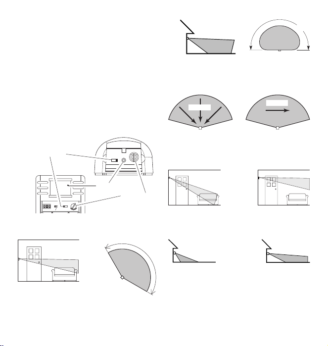
Outdoor Motion Sensor
ON-TIME Control
LED
Indicator
Range Control
Indoor Motion Sensor
Motion Sensor Controls
30 ft.
Maximum Range
(9.1 m)
Maximum
Coverage Angle
Indoor Motion Sensor Coverage Area
8 ft.
(2.4 m)
70 ft.
Maximum Range
(21 m)
Outdoor Motion Sensor Coverage Area
Motion
Sensor Sensor
The detector is most sensitive to motion across its field of view.
Maximum
Coverage Angle
Motion
Most SensitiveLeast Sensitive
Indoor and Outdoor Motion Sensor Sensitivity
Aim Sensor Down
for Short Coverage
Aim Sensor Higher
for Long Coverage
Adjusting Indoor Motion Sensor Coverage
150°
Aim Sensor Down
for Short Coverage
Aim Sensor Higher
for Long Coverage
Adjusting Outdoor Motion Sensor Coverage
6 598-1135-08
180°
Page 7
ADD-A-SWITCH
DI
M
DI
M
1 2 3 4
ON
2032
3
V
L
i
t
h
i
u
m
B
a
t
t
e
r
y
DIM
1 2 3 4
ON
DIM
2032
3
V
L
i
t
h
i
u
m
B
a
t
t
e
r
y
1. Remove Tab from Battery Chamber. Remove cover
2. Select mounting location for add-a-switch transmitter. Note: Trans-
mitter should be located within 100 feet (30 m) of receiver.
Note: Transmitter should be mounted approximately 4 feet from
the floor and in the vertical position.
3. Before mounting, hold transmitter in selected location and
verify operation (see Operation). Note: If transmitter does not
operate correctly, see Troubleshooting Guide.
4. With transmitter held in place, mark the mounting holes with
a pencil or pointed object.
5. Remove transmitter and drill two 3/16" holes. Tap drywall
anchors (provided) into holes with a hammer.
6. Attach transmitter to wall using two screws (provided).
1. Verify that receiver has been properly installed. See Receiver
Information, page 10.
2. Push the ON (top) button and release. The light should turn on
full bright.
3. Push the OFF (bottom) button and release. The light should
turn off.
4. Push the DIM button and release. The light should turn on at
a DIM level.
Installation
from front of Add-A-Switch transmitter. Gently pull tab
out of battery chamber. Slide cover onto Add-A-Switch
transmitter.
Battery Chamber
(Type CR2032)
Tab
Access Door
Removing Battery Tab
Operation
Add-A-Switch
DIM
Button
ON/OFF
Button
Access Door
Add-A-Switch
5. Continue to press the DIM button until the desired dim level is
reached. Note: Receiver remembers last DIM setting used. To
recall last DIM setting, push and release the DIM button.
Note: The DIM setting defaults to 50% in the event of a power
failure.
IMPORTANT: Wait 1 to 2 seconds after you press a transmitter
button before you press it again to allow the transmission to be
completed.
Note: If light does not turn on or intermittently turns on and off when
transmitter buttons are pushed, see Troubleshooting Guide.
The wall switch transmitter requires a type CR2032, 3-volt lithium
battery to operate. The transmitter is shipped with the battery
installed. With typical use, the battery will last approximately 5
years. Remove battery when transmitter will not be used for an
extended period of time.
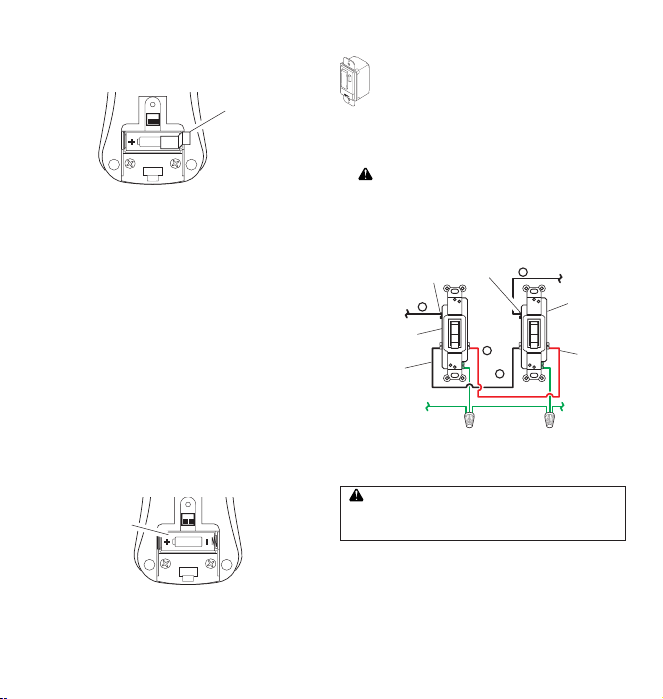
1. Place thumb on access door
and slide down to open.
2. Carefully bend locking tab
outward. Battery will pop up.
3. Remove battery from socket.
4. Install replacement battery in
socket plus (+) side up (see
illustration). Press down on
battery until locking tab snaps
into place.
5. R einstall acce ss door by
sliding it upward until it locks
in place.
Battery Replacement
Access
Door
Removing Access Door
and Battery
Battery
Locking
Tab
CR2032
Lithium
Battery
KID’S REMOTE CONTROL
Operation
1. Verify that receiver has been properly installed.
See Receiver Information, page 10.
Remote Control
Back
Philips-Head
Screw
Access
Door
7598-1135-08
Removing Access Door
ENGLISH
Page 8
TO HOT
OR LIGHT
TO HOT
OR LIGHT
1
BLACK
3
BLACK
GREEN
(Ground)
2
RED
4 BLACK
2. To remove tab from battery chamber, remove screw in access
ON
12V
ON
12V
DI
M
door of remote with a small phillips-head screwdriver. Gently
pull tab out of battery chamber. Reassemble access door in
reverse order.
Tab
Removing Tab In Battery Chamber
3. Push and release the ON button (left button) to turn light on or
the OFF button (right button) to turn light off. Note: Red light
on remote should come on while button is depressed.
IMPORTANT: Wait 1 to 2 seconds after you press a transmitter
button before you press it again to allow the transmission to be
completed.
Note: If light does not turn on or intermittently turns on and off when
remote buttons are pushed, see Troubleshooting Guide.
The remote control requires a type A23 12 Volt alkaline battery to
operate. The remote control is shipped with the battery installed.
With typical use, the battery will last approximately one year.
Remove battery when remote will not be used for an extended
period of time.
To replace the battery, follow the instructions below:
1. Turn remote control upside down.
2. Remove screw in access door of remote with a small phillipshead screwdriver.
3. Remove access door and lay aside.
4. Remove battery. Install replacement battery. Make sure battery
is oriented properly (see illustration).
5. Reassemble access door in reverse order.
Battery Replacement
Battery
Compartment
(Type A23)
Inside of Remote Control
3-WAY WALL SWITCH TRANSMITTER
Important: This product must be used in conjunction
with the Wall Switch Receiver. 3-way circuit wiring is
required to install and use this product.
Note: If you are not familiar with electrical wiring, consult
an electrician about installation. In addition, some local
building codes may require installation by a qualified electrician.
1. Select light switch to be replaced by 3-way wall switch transmitter.
2. WARNING: Turn off the power to the light switch circuit
before you proceed. Do this at your circuit breaker or fuse
box.
3. Remove the existing wall plate and switch. Label the wires on
the existing switch according to the diagram in Figure 1. Note:
Typical 3-way wiring is shown. Actual wiring and wire colors
may vary.
Installation
Common Terminal
(Dark Screw)
3-Way
Switch
3-Way Switch
Travel
Travel Wire
4. Disconnect the two travel wires, wire connected to common
5. Remove the wall plate from the 3-way wall switch transmitter.
must run continuously through the entire circuit. If present, do not connect a white neutral wire to either of the
3-way switch wires.
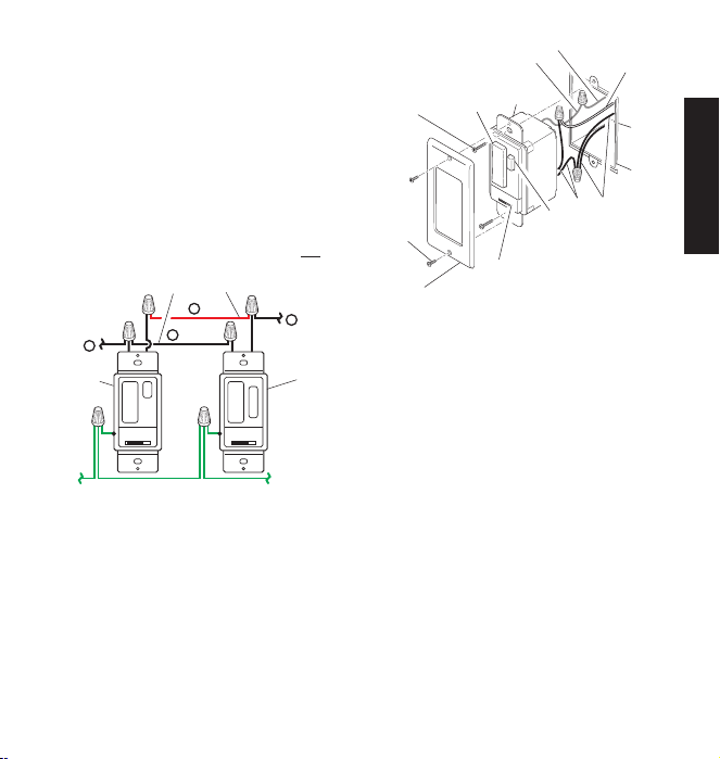
6. Connect the wires of the 3-way wall switch transmitter to the
7. Connect the green ground wire from transmitter to the ground
8. Check wire connections to make sure they are secure and that
8 598-1135-08
Figure 1 - Typical 3-Way Wiring
terminal, and the ground wire.
WARNING: The white neutral wires in a 3-way circuit
wires in the junction box as shown in Figure 2. Use the supplied
wire connectors to secure the wires (see Figure 2). Note: Either
black wire on the transmitter can be used to connect to the hot
wire (light) or traveler wire.
wire removed from old switch. Use one of the supplied wire
connectors to secure the wires (see Figure 3).
no bare wires are exposed.
Wire
Page 9
DI
M
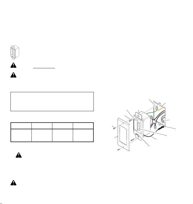
9. Position the wall switch transmitter in the junction box with the
TO HOT
OR LIGHT
TO HOT
OR LIGHT
1
BLACK
3
BLACK
GREEN (Ground)
DIM
1
BLACK
TO HOT
OR LIGHT
4
BLACK
GREEN
(Ground)
2 RED
2
RED
3 BLACK
4 BLACK
DIM button located to the right. Use the two wall switch screws
(long) supplied to mount the transmitter to the junction box (see
Figure 3). Push excess wiring into junction box while you do
this, bending the wires to fit if necessary.
10. Mount the wall plate to the wall switch transmitter with the
screws (short) provided.
11. To install the wall switch receiver, repeat steps 5 through 10
above. Note: Route antenna between the bottom of the junction
box and the wall. Feed antenna into wall cavity while placing
wall switch into junction box.
IMPORTANT: Label wires on existing 3-way switch according
to the diagram in Figure 1. Refer to Figure 2 below when connecting wall switch receiver wires to existing wires.
12. Turn on the power to the light switch circuit. Do this at your circuit
breaker or fuse box. Note: If the light turns on immediately and
remains on, reverse the travel wire connections on one of the
switches.
Travel Wires
Transmitter Receiver
Figure 2 - Wiring 3-Way Wall Switch
Green Ground Wire From Switch
Green (or Bare) Ground Wire
Wall
ON/OFF
Wall Switch
Screw
Button
Switch
Red Wire
(Typical)
Wall
Junction
Wall
Plate
Screw
Power
Wall Plate
1. Verify the power disconnect switch on the transmitter and
receiver is in the ON (right side) position.
2. Push the ON (top) button and release. The light should turn on
full bright. Note: If you are controlling a lamp, make sure it is
connected to the switched outlet and the lamp is switched on.
3. Push the OFF (bottom) button and release. The light should
turn off.
4. Push the DIM button and release. The light should turn on at
50% brightness (or last setting). Note: Receiver remembers
the last DIM setting used. To recall last DIM setting, push and
release the DIM button.
5. Continue to press the DIM button until the desired dim level is
reached. Note: There are 5 DIM settings ranging from 15% to
90% brightness.
Note: The DIM setting defaults to 50% in the event of a power
failure.
IMPORTANT: Wait 1 to 2 seconds after you press a transmitter
button before you press it again to allow the transmission to be
completed.
Note: If light does not turn on or intermittently turns on and off when
transmitter buttons are pushed, see Troubleshooting Guide.
Move the power disconnect switch on the transmitter and receiver to the
OFF (left side) position. Replace bulb(s). Note: The power disconnect
switch on the transmitter prevents the unit from sending any signals
to the receiver. The power disconnect switch on the receiver prevents
it from applying power to the load that it controls.
Disconnect
Switch
Figure 3 - Installing 3-Way Wall Switch
(Transmitter Shown)
Operation
Bulb Replacement
DIM
Button
Black Wire
9598-1135-08
ENGLISH
Box
Page 10
RECEIVER INFORMATION
All receivers have the following features and ratings:
• Rated for 120VAC/60Hz supply voltage.
• Uses existing wiring.
• Fits standard single gang junction box.
• Up to 100 feet (30 m) typical transmission range.
• When first turned on wait 15 seconds.
WALL SWITCH RECEIVER
Features and Ratings:
• Up to 500 Watt maximum incandescent load depending upon switch purchased. See rating label on switch
for exact load rating.
• Not for use with Compact Fluorescent bulbs.
WARNING: FOR USE ONLY with 120 volt incandescent
or halogen bulbs.
CAUTION: To reduce the risk of overheating and possible damage to other equipment, do not install to control a
receptacle, a motor-operated appliance, a fluorescent lighting
fixture, or a transformer-supplied appliance.
Important Information Regarding 3-Way Switch Installations:
In order to use this product where two switches are being used
to control the light, the 3-Way Wall Switch transmitter will also
have to be installed. Refer to the 3-Way Wall Switch Installation
section for details.
Important: When ganging these units, they must be derated as
follows:
Gang 1 2 3
300 W 300 W 300 W 300 W
500 W 500 W 475 W 450 W
1. Select light switch to be replaced by wall switch receiver.
2.
WARNING: Turn off the power to the light switch circuit
before you proceed. Do this at your circuit breaker or fuse box.
3. Remove the existing wall plate and switch. Disconnect the two
power wires and the ground wire.
Note: If there are more than two power wires attached to the switch,
consult an electrician about installation. In addition, some local building codes may require installation by a qualified electrician.
CAUTION: Do not con nect neutral (white wir e) to
switch.
Installation
4. If necessar y, strip away 1/2" of insulation from end of wires.
5. Connect one of the black power wires from receiver to one of the
power wires you removed from the old switch. Use one of the
supplied wire connectors to secure the wires (see illustration).
6. Connect the second black power wire from receiver to the other
power wire you removed from the old switch. Use one of the
supplied wire connectors to secure the wires (see illustration).
7. Connect the green ground wire from receiver to the ground
wire removed from old switch. Use one of the supplied wire
connectors to secure the wires (see illustration).
8. Check wire connections to make sure they are secure and that
no bare wires are exposed.
9. Route antenna between the bottom of the junction box and the
wall. Feed antenna into wall cavity while placing wall switch
into junction box.
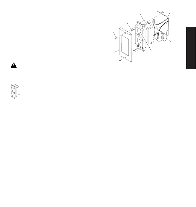
10. Position the wall switch receiver in the junction box with the DIM
button located to the right. Use the two wall switch screws (long)
supplied to mount the receiver to the wall box (see illustration).
Push excess wiring into wall box while you do this. You may
need to bend the wires to fit inside the box. Mount wall plate on
wall switch receiver with screws (short) provided.
11. Turn on the power to the light switch circuit. Do this at your
circuit breaker or fuse box.
Ground Wire (Bare or Green)
Wall
ON/OFF Button
Wall Switch Screw
Wall Plate
Screw
Wall Plate
1. Verify the power disconnect switch is in the ON (right side)
position.
2. Push the ON (top) button and release. The light should turn on
full bright. Note: If you are controlling a lamp, make sure it is
connected to the switched outlet and the lamp is switched on.
3. Push the OFF (bottom) button and release. The light should
turn off.
10 598-1135-08
Switch
Installing Wall Switch Receiver
Operation
Junction Box
(Neutral)
DIM Button
Antenna
Power Disconnect Switch
White
Wall
Page 11
C
O
N
T
R
O
L
L
E
D
C
O
N
T
R
O
L
L
E
D
4. Push either the top or bottom of DIM button and release. The
light should turn on at 50% brightness (or last setting).
5. Push and release top of DIM button to increase brightness.
Push and release bottom of DIM button to decrease brightness. Note: There are 5 DIM settings ranging from 15% to 90%
brightness.
6. Set desired DIM level. Note: DIM setting remembers last setting used. To recall last DIM setting from ON or OFF, push and
release either the top or bottom of DIM button.
Note: The DIM setting defaults to 50% in the event of a power
failure.
Move the power disconnect switch to the OFF (left side) position.
Replace bulb(s).
CAUTION: Do not exceed the maximum load limits
listed above.
1. Remove existing receptacle from junction box, if necessary.
2. Connect green wire from receptacle to ground wire in junction
box. Connect the black wire on receptacle to the load wire in
junction box and connect the white wire on receptacle to the
neutral wire in the junction box. Connections should appear as
shown in illustration. Before installing fixture, make sure there
is no wire exposed at connections.
3. Mount receptacle in junction box with the two screws (long)
provided. Note: Verify the receptacle marked “CONTROLLED”
is on top.
4. Screw on cover plate with the two screws (short) provided.
Bulb Replacement
RECEPTACLE RECEIVER
Features and Ratings:
• Control up to 1800 Watts of incandescent load.
• Controls the ON/OFF function in lighting.
• Controls up to 15A loads.
Installation
Receptacle
Screw
Wall Plate
Screw
Ground Wire
Wall Plate
(Bare or Green)
Controlled Outlet
Installing Receptacle Receiver
Junction BoxReceptacle
Follow the steps below to operate and test the receptacle receiver
using a remote control device:
1. Set the proper channel codes on both the transmitter and
receiver modules (see Code Settings).
2. Plug in the light fixture to be controlled in the top receptacle.
Note: If installed properly, the top receptacle will be marked
with the word “CONTROLLED” below it.
3. Operate the ON/OFF buttons on the remote to verify operation.
Light should turn ON and OFF as the appropriate button is
pressed.
Note: DIM is not available on this switch.
Testing and Operation
ENGLISH
11598-1135-08
Page 12

TROUBLESHOOTING GUIDE
SYMPTOM POSSIBLE CAUSE SOLUTION
Device does not come on. 1. Circuit breaker or fuse is turned off.
2. Switch on device is turned off.
3. Interrupted by another device.
4. Does not respond immediately after
installation.
5. Signals from transmitt er are being
bloc ked, o r tran smitter is out of
range.
6. Weak battery in the transmitter.
7. Dip switches on transmitter and receiver
units do not match.
8. Device is defective.
Device does not turn off. 1. Same as 5, 6, and 7 above. 1. Same as 5, 6, and 7 above.
Device comes on randomly. 1. Shor t term power line failure.
2. A nother tr ansmitt er on t he same
frequency.
1. Verify circuit breaker or fuse is turned
on.
2. Verify switched device is turned on.
3. Change codes on transmitter and
receiver units.
4. Wait for 90 second initialization period
(remote motion sensor).
5. Check for metal objects that could
block the signal, or reposition the
transmitter.
6. Check battery charge and replace if
necessary.
7. Verify code settings on transmitter
and receiver units are set the same.
8. Test using different device.
1. Next transmission from transmitter
will reset receiver to correct state.
2. Change codes on transmitter and
receiver units.
Please call 1-800-858-8501 (English speaking only) for assistance before returning product to store.
TECHNICAL SERVICE
If you experience a problem, follow this guide. You may also want to visit our Web site at: www.hzsupport.com. If the problem persists,
call* for assistance at 1-800-858-8501 (English speaking only), 7:30 AM to 4:30 PM CST (M-F). You may also write* to:
HeathCo LLC
P.O. Box 90004, Bowling Green, KY 42102-9004
ATTN: Technical Service
* If contacting Technical Service, please have the following information available: Model Number, Date of Purchase, and Place of
Purchase.
This device complies with Part 15 of the FCC Rules and RSS-210 of Industry Canada. Operation is subject to the following two conditions:
(1) this device may not cause harmful interference, and (2) this device must accept any interference received, including interference
that may cause undesired operation.
The user is cautioned that changes or modifications not expressly approved by the party responsible for regulatory compliance could
void the user’s authority to operate the equipment.
No Service Parts Available for this Product
REGULATORY INFORMATION
12 598-1135-08
Page 13
This is a “Limited Warranty” which gives you specific legal rights. You may also have other rights which vary from state to state
or province to province.
For a period of two years from the date of purchase, any malfunction caused by factory defective parts or workmanship will be
corrected at no charge to you.
Not Covered - Repair service, adjustment and calibration due to misuse, abuse or negligence, light bulbs, batteries, and other
expendable items are not covered by this warranty. Unauthorized service or modification of the product or of any furnished
component will void this warranty in its entirety. This warranty does not include reimbursement for inconvenience, installation,
setup time, loss of use, unauthorized service, or return shipping charges.
This warranty covers only HeathCo LLC assembled products and is not extended to other equipment and components that a
customer uses in conjunction with our products.
THIS WARRANTY IS EXPRESSLY IN LIEU OF ALL OTHER WARRANTIES, EXPRESS OR IMPLIED, INCLUDING ANY
WARRANTY, REPRESENTATION OR CONDITION OF MERCHANT ABILITY OR THAT THE PRODUCTS ARE FIT FOR
ANY PARTICULAR PURPOSE OR USE, AND SPECIFICALLY IN LIEU OF ALL SPECIAL, INDIRECT, INCIDENTAL, OR
CONSEQUENTIAL DAMAGES.
REPAIR OR REPLACEMENT SHALL BE THE SOLE REMEDY OF THE CUSTOMER AND THERE SHALL BE NO LIABILITY ON
THE PART OF HEATHCO LLC FOR ANY SPECIAL, INDIRECT, INCIDENTAL, OR CONSEQUENTIAL DAMAGES, INCLUDING
BUT NOT LIMITED TO ANY LOSS OF BUSINESS OR PROFITS, WHETHER OR NOT FORESEEABLE. Some states or provinces
do not allow the exclusion or limitation of incidental or consequential damages, so the above limitation or exclusion may not apply to
you. Please keep your dated sales receipt, it is required for all warranty requests.
HeathCo LLC reser ves the right to discontinue products and to change specifications at any time without incurring any obligation to
incorporate new features in products previously sold.
TWO YEAR LIMITED WARRANTY
ENGLISH
13598-1135-08
Page 14
Productos a control remoto
DIM
ON
OFF
ON
OFF
DIM
Este manual incluye las instrucciones de operación para una variedad de productos a control remoto. Todos los productos funcionan
basándose en el mismo principio y usan la misma información para la calibración del código. Por favor lea todas las instrucciones y
tome en cuenta cualquier información específica relativa a su producto en particular.
Este manual sirve para los siguientes productos:
• Transmisores
– Control remoto
– Detector inalámbrico de movimiento
para uso interior
– Detector inalámbrico de mov-
imiento para uso exterior
– Interruptor A añadible
– Control remoto para niños
– Conmutador tridireccional de pared
CALIBRACIONES DEL CÓDIGO
Nota: La mayoría de instalaciones de sólo un sistema no requerirán ningún cambio en la calibración del código. Para que funcionen juntos los transmisor(es) y los receptor(es) deben tener
la misma calibración de código y de grupo. Los interruptores
del 1 al 3 fijan el código. El interruptor 4 fija el grupo (A o B). Vea
en la página 15 la ubicación de los interruptores.
Ejemplo 1 - Calibraciones del código, sistema 1
Controles del
lado izquierdo:
Controla un juego de
receptor(es) del gru-
po “A” o grupo “B”
Código del transmisor(es)/
(calibración de fábrica)
receptor(es)
• Receptores
– Receptor de pared con
interruptor
– Receptor con tomaco-
rriente
Controles del lado
derecho: Controla un
juego de receptores
del grupo “A” o grupo
“B”
Código del transmisor(es)/
receptor(es)
• Productos probados y aprobados por laboratorios UL/cUL y/o
FCC/IC.
• Distancia de operación: hasta 100 pies.
Los controles inalámbricos Heath®/Zenith para el alumbrado están
diseñados para trabajar juntos. Simplemente determine cual
transmisor(es) le gustaría que controlen tal(es) receptor(es) y fije
la calibración del código para emparejar.
Ejemplo 2 - Calibraciones del código, sistema 2
Nota: Cuando opere más de un sistema independientemente el uno del
otro, fije cada sistema con un código diferente. Hay 8 códigos disponibles al cambiar las calibraciones de los interruptores del 1 al 3.
Cuando se use un transmisor de sólo un grupo (ejemplo: Transmisor
de puerta, interruptor “A” añadible, detector remoto de movimiento)
las calibraciones de código y grupo deben emparejar con los
receptor(es) para que el sistema funcione correctamente.
CARACTERISTICAS
Código del
receptor(es)
Grupo “A”
Ejemplo 3 - Calibraciones del código con un
Código del
receptor(es)
único transmisor
Código del
transmisor(es)
Interruptor del grupo
(Selección Grupo “A” mostrada)
Código del detector
remoto de movimiento
Grupo “A”
( – Indica la posición del interruptor)
© 2007 HeathCo LLC 598-1135-08 S
Grupo “B”
14 598-1135-08
Grupo “A”
Nota: Esta calibración funcionará independientemente de los
ejemplos uno y dos porque la calibración del código es diferente.
Nota: El código puede también cambiarse para reducir los problemas
de interferencia que vienen de otros productos inalámbricos. (ejem-
plo: Teléfonos inalámbricos, abridores de puertas de garajes, etc.)
Para más información vea Guía de Análisis de Averías.
Grupo “A”
Page 15

UBICACIONES DE LOS INTERRUPTORES DE CIRCUITO IMPRESO
1 2 3 4
ON
2032
3
V
L
i
t
h
i
u
m
B
a
t
t
e
r
y
DIM
1 2 3 4
ON
DETECT
CODES
123 4
DAY
NIGHT
NIGHT
ONLY
ON
12V
ON
C
O
N
T
R
O
L
L
E
D
O
N
1
2 3
4
ON
1 2 3
4
ON
DIM
ON DIP
1 2 3 4
ON DIP
1 2 3 4
CODE
1 2 3 4
ON
5 1 TEST
ON-TIME
(MINUTES)
MIN MAX
DETECT
RANGE
DAY
NIGHT
NIGHT
ONLY
Interruptores
de código
del lado
izquierdo
Tapa de la
batería
Tapa de
acceso
Control remoto
Interruptores
Interruptores de
circuito impreso
de código
del lado
derecho
Interruptores
de circuito
impreso
Detector inalámbrico de movimiento
para uso interior
Control remoto para niñosInterruptor A añadible
Interruptores
de circuito
Interruptores
de circuito
impreso
impreso
Receptor de pared con interruptor Receptor con tomacorriente
15598-1135-08
Interruptores
de circuito
impreso
Interruptores
de circuito
impreso
Detector inalámbrico de movimiento
para uso exterior
Interruptores
de circuito
impreso
Conmutador tridireccional de pared
Nota: La “X” ha sido colocada en los
interruptores para ayudar a aclarar las
calibraciones del código de la página
Vista ampliada de un interruptor típico
del código (la calibración hecha en
anterior.
fábrica es OFF- apagado)
ESPAÑOL
Page 16

CONTROL REMOTO
4 5 43
1 2 32
ON DIP
1 2 3 4
ON DIP
1 2 3 4
Nota: Un control remoto puede operar independientemente
dos unidades receptoras. Si se desea operar independientemente más de dos receptores, se necesitarán comprar
controles remotos adicionales.
1. Retire la aleta del compartimento de la batería. Retire la
tapa posterior del transmisor. Hale la aleta con suavidad
fuera del compartimento de la batería. Deslice la tapa
en el transmisor.
Compartimento
de la batería
(tipo A23)
Vista posterior del control remoto
2. Funciones del control remoto. Los tres botones del lado izquierdo del control remoto hacen funcionar a una o más unidades
receptoras que tienen la misma calibración del código. Los tres
botones de la derecha harán funcionar un segundo juego de uno
o más receptores.
• ON: Enciende cualquier unidad receptora del mismo código que
este control remoto.
• OFF: Apaga cualquier unidad receptora del mismo código que
este control remoto.
• DIM: Activa la característica REDUCTORA de cualquier unidad
receptora del mismo código que este control remoto. Nota: Al pulsar
el botón DIM se pasa por los cinco niveles de luminosidad.
Aleta
Tapa de la batería
Nota: Para operar independientemente una segunda unidad receptora usando un único control remoto, asegúrese que el segundo
juego de interruptores de código (del lado derecho) emparejen
con los interruptores de código de cada receptor (Ver la sección
Calibraciones del Código).
• Lado izquierdo - Para calibrar los interruptores de código del
lado izquierdo.
• Lado derecho - Para calibrar los interruptores de código del
lado derecho.
Lado izquierdo DIM
Lado izquierdo
(ON)ENCENDIDO
Lado izquierdo
(OFF)APAGADO
Lado derecho DIM
Lado derecho
(ON)ENCENDIDO
Lado derecho
(OFF)APAGADO
Controles de las funciones
IMPORTANTE: Espere de 1 a 2 segundos después de pulsar el
botón de un transmisor antes de pulsarlo de nuevo para permitir
que la transmisión se complete.
Nota: Si la luz no se prende o si se prende y apaga intermitentemente cuando se pulsan los botones del transmisor, vea la Guía
de Análisis de Averías.
Presilla opcional del visor del carro (incluida)
Para mayor conveniencia, en el control remoto se incluye una presilla
opcional del visor del carro que puede ser instalada.
1. Para unir (si se desea)la presilla del visor del carro al control
remoto empújela contra la ranura de la parte posterior del
control hasta que se cierre a presión en su lugar.
2. Para retirar esta presilla, inserte un destornillador plano
pequeño en la ranura de la parte posterior del control. Con
el destornillador, empuje suavemente la porción de la presilla
del visor que está dentro de la ranura mientras desde arriba
hala la presilla hacia fuera del control.
Destornillador
plano
Presilla
opcional del
visor
Retiro de la presilla del visor – Vista posterior
16 598-1135-08
Page 17

DETECTOR INALÁMBRICO DE MOVIMIENTO
O
N
Da
y
/ Ni
g
h
t
N
ight
O
nl
y
5
1
Te
st
Ma
x
Mi
n
DETECT
CODES
12 3 4
DAY
NIGHT
NIGHT
ONLY
CODE
1 2 3 4
ON
5 1 TEST
ON-TIME
(MINUTES)
MIN MAX
DETECT
RANGE
DAY
NIGHT
NIGHT
ONLY
PARA USO INTERIOR Y EXTERIOR
Control
detector
Detector inalámbrico de
movimiento para uso
interior
Características:
• No se requiere cableado.
• Margen de sensibilidad hasta 21 m. 180° de cobertura (Exterior).
•
Margen de sensibilidad hasta 9.1 m. 150° de cobertura (Interior).
• Sensibilidad ajustable.
• Operación diurna/nocturna o sólo nocturna.
• Modo prueba.
• Usa dos baterías AA.
• Montaje en pared o alero (Exterior).
• Puede instalarse directamente en la pared o usando un soporte
de montaje (incluido) (Interior).
• Controla los receptores hasta 30 m de distancia.
Seleccione modo nocturno o modo de 24 horas
Estos detectores pueden detectar movimiento durante el día o la
noche o sólo por la noche. Para fijar el modo de detección, retire
la tapa del compartimiento de la batería deslizándola hacia abajo.
Si es necesario retire las baterías. Mueva el interruptor DETECT
(DETECTAR) ya sea a la posición DAY/NIGHT ó a la posición NIGHT
ONLY (SÓLO NOCHE). Vuelva a colocar el compartimiento de la
batería siguiendo a la inversa las instrucciones indicadas.
• Antes de montar el detector de movimiento para uso exterior,
retire la tapa del compartimiento de la batería deslizándola hacia
abajo.
• En detectores de movimiento para uso interior, instale las baterías
luego de colocar el detector.
Coloque las dos baterías AA según la polaridad marcada dentro del
compartimento de la batería. Vuelva a colocar el compartimiento de
la batería siguiendo a la inversa las instrucciones indicadas.
Instalación de las baterías
Detector inalámbrico de
movimiento para uso
exterior
Detector de movimiento
para uso exterior
(Vista posterior)
Detector de movimiento
para uso interior
(Vista frontal)
Compartimento de la batería
Instalación del detector de movimiento para uso
interior usando el soporte opcional de montaje
Nota: Instale el detector de movimiento para uso interior de modo
que pueda girar hacia arriba o hacia abajo y así darle la cobertura
deseada por encima del nivel del suelo.
1. Fije la consola de montaje tipo bola a la parte posterior del
detector de movimiento. La consola de montaje tipo bola está
diseñada para instalarse en la parte posterior del detector en
tres direcciones posibles dependiendo de lo requerido por la
instalación. Para sujetar la consola de montaje tipo bola siga
los pasos que se indican:
• Determine la posición óptima de montaje del detector para
obtener la cobertura deseada.
• Determine el sitio óptimo de la consola de montaje para pared.
Parte posterior del
Tornillo del soporte
de montaje tipo
bola
detector
Ranuras para
la aleta
Aleta
Consola de montaje
tipo bola
Sujeción de la consola de montaje tipo bola al
detector de movimiento para uso interior
(se muestra la instalación vertical)
Continuación
17598-1135-08
Montura
giratoria
de bola
ESPAÑOL
Page 18

• Inserte las aletas de la consola de montaje tipo bola en las
O
N
D
ay
/
N
ight
Night
Only
5 1
Te
s
t
M
ax
M
in
O
N
D
ay
/
N
ig
h
t
N
ig
ht
On
l
y
5
1
T
es
t
M
a
x
Mi
n
O
N
D
a
y
/
N
ig
h
t
N
i
g
h
t
O
n
ly
5
1
T
e
st
Ma
x
M
i
n
O
N
D
a
y
/
N
ig
h
t
N
ig
h
t
O
n
l
y
5
1
T
e
s
t
M
a
x
M
in
O
N
D
a
y
/
Ni
g
h
t
N
ig
h
t
O
n
l
y
5
1
T
e
s
t
M
a
x
Mi
n
ranuras de la parte posterior del detector que mejor alineen
este detector con la consola de montaje de pared.
• Retire las baterías.
• Con un destornillador cabeza Phillips, inserte el tornillo de
montaje en el orificio del compartimiento de la batería que
alinee con el orificio posterior de la consola de montaje tipo
bola. Apriete bien.
2. Coloque el soporte de montaje del detector sobre la superficie
que lo va a instalar y con un lápiz o un punzón de marcar,
marque la ubicación del orificio.
3. Con una broca de 2,5 mm. (0,1 pulgadas), taladre dos orificios
guía para los tornillos de montaje. Si no lo instala directamente
a la madera o al espárrago de la madera, taladre orificios guía
de 5mm (0,2 pulgadas) y utilice las anclas de pared que se
incluyen.
4. Usando los dos tornillos provistos, fije el detector de movimiento
para uso interior a un objeto sólido y fir me (ejemplo: pared,
armario, poste, etc.). Asegúrese que la unidad no tenga
obstrucciones en su línea de mira. Nota: Sujete la consola
de montaje verticalmente si lo instala a una superficie curva
como un poste.
5. Instale el detector de movimiento a la consola de montaje.
Usando un destornillador cabeza Philips, afloje el tornillo de
la abrazadera en la consola de montaje. Inser te la montura
giratoria de bola del detector en el zócalo de la consola de
montaje (Nota: Usted debería oír un chasquido -un clic-). Apunte
el detector hacia el área que se requiere detectar. Apriete el
tornillo de la abrazadera.
Zócalo de la consola
de montaje
Consola de
montaje
Tornillo de la
abrazadera
Tuerca
Tornillo de montaje
Montura giratoria de bola
Tapa del compartimiento
de la batería
Sujeción del detector de movimiento para uso interior a la
consola de montaje
Detector
Instalación del detector de movimiento para uso
interior directamente en la pared
Nota: Instale el detector de movimiento para uso interior de modo que
quede aproximadamente a una altura sobre el suelo entre la cintura
y los hombros. (Ejemplo: Al mismo nivel o altura que un interruptor
de luz, debajo de la superficie superior del mostrador, etc.).
1. Deter mine la posición óptima de montaje del detector para
obtener la cobertura deseada. Retire las baterías.
2. Coloque el detector de movimiento para uso interior sobre la superficie que lo va a instalar. Usando dos de los orificios posteriores
del compartimiento de la batería marque, con un lápiz o con un
punzón de marcar, las ubicaciones de los orificios.
3. Con una broca de 2,5 mm. (0,1 pulgadas), taladre dos orificios
guía para los tornillos de montaje. Si no lo instala directamente
a la madera o al espárrago de la madera, taladre orificios guía
de 5mm (0,2 pulgadas) y utilice las anclas de pared que se
incluyen.
4. Usando los dos tornillos provistos, fije el detector de movimiento para uso interior a un objeto sólido y firme (ejemplo:
pared, armario, poste, etc.). Asegúrese que la unidad no tenga
obstrucciones en su línea de mira.
IMPORTANTE: Apriete a mano solamente - No apriete de-
masiado.
Detector de
movimiento
Tornillo de
montaje
Superficie
superior del
mostrador
Fijación del detector de movimiento directamente a la pared
18 598-1135-08
Page 19

Instalación del detector de movimiento para uso
1. Instale la consola de montaje del detector en donde se necesite detectar movimiento. Acople esta consola de montaje a
un objeto robusto (ejemplo: árbol, poste, casa, etc.) usando
los dos tornillos provistos. Asegúrese que la unidad no tenga
obstrucciones en su línea de mira. Nota: Sujete la consola de
montaje verticalmente si lo instala a una superficie curva como
un poste.
2. Instale el detector de movimiento a la consola de montaje.
Usando un destornillador cabeza Philips, afloje el tornillo de
la abrazadera en la consola de montaje. Inser te la montura
giratoria de bola del detector en el zócalo de la consola de
montaje (Nota: Usted debería oír un chasquido -un clic-). Apunte
el detector hacia el área que se requiere detectar. Apriete el
tornillo de la abrazadera.
IMPORTANTE: El detector debe estar montado con la tapa
inferior hacia abajo con el fin de mantener la hermeticidad
contra el agua.
Zócalo de la consola
de montaje
Tornillo de la
abrazadera
Montura giratoria
de bola
Instalación del detector de movimiento
Detector
exterior
Tuerca
Consola de montaje
Tornillo de montaje
Revisión de la operación y de la regulación
Nota: Cuando lo prenda por primera vez o cuando cambie de
modalidad espere 1 1/2 minutos.
Localice en el detector de movimiento los controles de ALCANCE
y DURACIÓN:
• Detector de movimiento para uso interior - los controles de
ALCANCE y DURACIÓN están dentro del compartimiento de
la batería en la parte frontal del detector. Para fijar el control de
ALCANCE o el de DURACIÓN, retire la tapa del compartimiento
de la batería deslizándola hacia abajo.
• Detector de movimiento para uso exterior - Los controles
de ALCANCE y DURACIÓN están ubicados en la parte inferior
del detector. Usando las uñas de los dedos o un destornillador
pequeño de cabeza plana, haga suavemente palanca en la tapa
hasta que se abra.
1. Revise la operación. Ponga el control de DURACIÓN en el modo
TEST (PRUEBA). Camine frente a la unidad detectora. La luz
indicadora LED debe destellar cuando se detecta movimiento
(vea la ilustración de la página 20 para ubicar la luz LED).
2. Regule el detector. Gire el control de ALCANCE a la posición
media y el de DURACIÓN a la posición TEST. Camine por el
área de cobertura y note su posición cuando el LED empiece a
destellar. Afloje el tornillo de la abrazadera y mueva el detector
para cambiar el área de cobertura. Cuando termine apriete
el tornillo de la abrazadera. No apriete excesivamente este
tornillo.
3. Regule el control de alcance. Para incrementar la sensibilidad,
gire el control de ALCANCE hacia MAX. Para disminuir la
sensibilidad, gírelo hacia MIN. Nota: En algunos ambientes
si el ALCANCE se calibra demasiado alto, puede ocurrir una
falsa activación.
Nota: Cuando use el modo de prueba (Test) para comprobar
el funcionamiento durante el día:
A. Ponga el interruptor del control DETECT (DETECTAR) a
DAY/NIGHT (NOCHE/DÍA) y
B. Ponga el control ON-TIME (DURACIÓN) a TEST.
4. Fije el control de DURACIÓN. Determine la cantidad de tiempo
que desea que el dispositivo conectado permanezca encendido
luego que se detecta movimiento (1 ó 5 minutos). Mueva el
control de DURACIÓN a la configuración correspondiente.
IMPORTANTE: Evite apuntar el control:
• Objetos que cambian rápidamente la temperatura, como sopladeros
de la calefacción, ventiladores y acondicionadores de aire. Estas
fuentes de calor podrían ocasionar una activación falsa.
• A áreas en donde las mascotas o el tráfico pueden activar el
control.
• En las cercanías de objetos grandes pintados con colores claros
cuyo reflejo puede activar el apagado. No enfoque otras luces al
detector.
19598-1135-08
Continuación
ESPAÑOL
Page 20

5 1 TEST
ON-TIME
(MINUTES )
RANGE
MAX
MIN
CODE
1 2 3 4
ON
5 1 TEST
ON-TIME
(MINUTES)
MIN MAX
DETECT
RANGE
DAY
NIGHT
NIGHT
ONLY
Detector de movimiento
Control de
DURACIÓN
Indicador
Detector de movimiento
para uso interior
Controles del detector de movimiento
para uso exterior
LED
Control de alcance
MovimientoMovimiento
Detector Detector
El detector es más sensible a movimientos transversales a su
campo de mira.
Sensibilidad del detector de movimiento para uso interior
Sensibilidad máximaSensibilidad mínima
y exterior
9.1 m
Alcance máximo
Área de cobertura del detector de movimiento para uso
interior
Ángulo máximo de
2.4 m
21 m
Alcance máximo
Area de cobertura del detector de movimiento para uso
exterior
Ángulo máximo de
cobertura
cobertura
Apunte el detector
hacia abajo para una
150°
cobertura menor
Regulación de la cobertura del detector de movimiento para
Apunte el detector
hacia abajo para una
cobertura menor
Regulación de la cobertura del detector de movimiento para
180°
uso interior
uso exterior
Apunte el detector
hacia más arriba para
una cobertura mayor
Apunte el detector
hacia más arriba para
una cobertura mayor
20 598-1135-08
Page 21

INTERRUPTOR A AÑADIBLE
DI
M
DI
M
1 2 3 4
ON
2032
3
V
L
i
t
h
i
u
m
B
a
t
t
e
r
y
DIM
1 2 3 4
ON
DIM
2032
3
V
L
i
t
h
i
u
m
B
a
t
t
e
r
y
1. Retire la aleta del compartimiento de la batería.
Instalación
Retire la tapa de la parte frontal del transmisor con
interruptor A añadible. Retire con suavidad la aleta
del compartimiento de la batería. Deslice la tapa en
el transmisor interruptor A añadible.
Aleta
Botón ON/OFF
(encendido/
apagado)
Interruptor A
añadible
Botón
atenuador
(DIM)
Compartimiento
de la batería (Tipo
CR2032)
Tapa de acceso
Retiro de la aleta de la batería
2. Seleccione un lugar para instalar el transmisor con interruptor
A añadible. Nota: El transmisor debería ubicarse hasta 100
pies (30m) del receptor. Nota: El transmisor debe montarse
aproximadamente a 4 pies del piso y en posición vertical.
3. Antes del montaje, sostenga el transmisor en la posición
seleccionada y verifique su operación (vea Operación). Nota:
Si el transmisor no opera correctamente, vea Guía del Análisis
de Averías.
4. Sostenga el transmisor en el sitio y marque los orificios de
montaje con un lápiz o con un objeto punzante.
5. Retire el transmisor y taladre orificios de 3/16 pulgadas.
Usando un martillo inserte en los orificios las anclas para
pared (provistas).
6. Fije el transmisor a la pared usando los dos tornillos (provistos).
1. Verifique que el receptor haya sido instalado correctamente.
Vea Información del receptor en la página 24.
2. Pulse y suelte el botón ON (parte superior). La luz debería
encenderse con luminosidad total.
3. Pulse y suelte el botón OFF (parte inferior). La luz debería
apagarse.
4. Pulse y suelte el botón atenuador. La luz debería encenderse
al nivel ATENUADOR.
Operación
Tapa de acceso
Interruptor A añadible
5. Continúe presionando el botón atenuador (DIM) hasta alcanzar
el nivel de atenuación deseado. Nota: El receptor memoriza la
última calibración de ATENUACIÓN usada. Para volver a la
última calibración, pulse y suelte el botón atenuador (DIM).
Nota: En caso de una falla de energía, la calibración del atenuador
se fija en el ajuste hecho en fábrica del 50%.
Importante: Luego de presionar un botón del transmisor espere
de 1 a 2 segundos para presionarlo de nuevo y permitir que se
complete la transmisión.
Nota: Si al presionar los botones del transmisor la luz no se
enciende ni lo hace en forma intermitente, vea Guía de Análisis
de Averías.
El transmisor del interruptor de pared requiere para operar una
batería de litio de 3 voltios tipo CR2032. El transmisor se lo envía
con la batería instalada. Con uso normal la batería dura aproximadamente 5 años. Retire la batería cuando no se vaya a utilizar
el transmisor por un período de tiempo extenso.
1. Coloque el pulgar en la tapa de acceso y deslícela hacia abajo
2. D oble hacia fue ra y con
3. Retire la batería del zócalo.
4. Instale en el zócalo la batería
5. Vuelva a colocar la puerta de
Reemplazo de la batería
para abrirla.
suavidad la aleta de traba.
La batería saltará.
de repuesto con el lado (+)
hacia arriba (vea la ilustración)
Presione la batería hasta que
la aleta de traba se cierre a
presión en su sitio.
acceso deslizándola hacia
arriba hasta que se fije en
su sitio.
Tapa de
acceso
Retiro de la tapa de
acceso y la batería
Aleta de
traba de la
batería
Batería
CR2032
21598-1135-08
ESPAÑOL
de litio
Page 22

ON
12V
CONTROL REMOTO PARA NIÑOS
DI
M
ON
12V
AL CONDUCTOR
VIVO O A LA
LÁMPARA
AL CONDUCTOR
VIVO O A LA
LÁMPARA
1
NEGRO
3
NEGRO
VERDE
(Tierra)
2
ROJO
4 NEGRO
Operación
1. Verifique que el receptor haya sido instalado
correctamente. Vea Información del receptor
en la página 24.
Parte posterior
Tornillo cabeza
Phillips
del control
remoto
Para cambiar la batería, siga las siguientes instrucciones:
1. Voltee el control remoto.
2. Retire el tornillo de la tapa de acceso del control remoto
utilizando un destornillador tipo Phillips.
3. Retire la tapa de acceso y póngala a un lado.
4. Retire la batería. Instale la batería de repuesto. Asegúrese instalar
la batería con la orientación correcta (vea la ilustración).
5. Vuelva a colocar la tapa de acceso en el orden inverso.
Compartimiento
de la batería
(Tipo A23)
Tapa de
acceso
2. Para retirar la aleta del compartimiento de la batería, retire el
Retiro de la puerta de acceso
tornillo de la puerta de acceso del control remoto usando un
destornillador tipo Phillips. Hale con suavidad la aleta hacia
fuera del compartimiento de la batería. Vuelva a colocar la tapa
de acceso siguiendo el orden inverso.
Aleta
Retiro de la aleta del compartimiento de la batería
3. Pulse y suelte el botón ON (botón izquierdo) para encender o
el botón OFF (botón derecho) para apagar la luz. Nota: La luz
roja en el control remoto debe encenderse cuando se presiona
el botón.
IMPORTANTE: Luego de presionar un botón del transmisor, espere
de 1 a 2 segundos para presionarlo de nuevo y permitir que se
complete la transmisión.
Nota: Si al presionar los botones del transmisor la luz no se
enciende ni lo hace en forma intermitente, vea Guía de Análisis
de Averías.
El control remoto requiere para operar una batería alcalina de 12
voltios tipo A23. El control remoto viene con la batería instalada.
Con uso normal la batería dura aproximadamente un año. Retire
la batería cuando no se vaya a utilizar el transmisor por un período
de tiempo extenso.
Reemplazo de la batería
Interior del control remoto
TRANSMISOR DE PARED CON
CONMUTADOR TRIDIRECCIONAL
IMPORTANTE: Este producto debe usarse junto con un
receptor de pared con interruptor. Para instalar y usar
este producto se necesita que haya una instalación con
circuito conmutado.
Nota: Si no está familiarizado con este cableado eléctrico,
consulte con un electricista para su instalación. Además algunos
códigos locales sobre edificios pueden exigir que la instalación la
realice un electricista calificado.
1. Seleccione el interruptor de luz que será reemplazado por el
transmisor de pared con conmutador tridireccional.
2. ADVERTENCIA:
de la lámpara antes de proceder. Haga esto en su disyuntor o
en la caja de fusibles.
3. Retire la placa y el interruptor de pared existentes. Identifique
a los conductores del interruptor existente según el diagrama
de la Figura 1.
Nota: Aquí se muestra el cableado de un circuito conmutado típico.
El cableado real y los colores de los conductores pueden variar.
Terminal común (tornillo oscuro)
Interruptor
tridireccional
Conductor retorno
(o vuelta)
Figura 1 - Cableado de un circuito conmutado típico
22 598-1135-08
Instalación
Apague la energía al circuito del interruptor
Interruptor
tridireccional
Conductor
retorno (o
vuelta)
Page 23

AL CONDUCTOR
VIVO O A LA
LÁMPARA
AL CONDUCTOR
VIVO O A LA
LÁMPARA
AL CONDUCTOR
VIVO O A LA
LÁMPARA
1
NEGRO
3
NEGRO
VERDE (Tierra)
DIM
1
NEGRO
4
NEGRO
VERDE
(Tierra)
2 ROJO
2
ROJO
3 NEGRO
4 NEGRO
4. Desconecte los dos conductores retornos, el conductor conec-
DI
M
tado al terminal común y el conductor de conexión a tierra.
5. Retire la placa de pared del transmisor con conmutador
tridireccional.
ADVERTENCIA: Los conductores neutros color blanco
del circuito conmutado tridireccional deben r ecorrer
por todo el circuito sin interrupción. Si se presenta este
conductor, no lo conecte a ninguno de los conductores
que van al interruptor tridireccional.
6. Conecte los conductores del transmisor con conmutador tridireccional a los conductores de la caja de empalmes como se
muestra en la figura 2. Para empalmar estos conductores, use
los conectores para conductores que se provee (vea la Figura
2). Nota: Cualquiera de los conductores negros del transmisor
pueden usarse para conectar al conductor vivo o fase (o a la
lámpara) o al conductor retorno.
7. Conecte el conductor verde de conexión a tierra del transmisor
al conductor de conexión a tierra que se retiró del interruptor
viejo. Use uno de los conectores de alambre provistos para
asegurar los conductores (vea la Figura 3).
8. Revise las conexiones de los conductores para asegurarse que estén
bien hechas y que no haya conductores desnudos a la vista.
9. Coloque en la caja de empalme el transmisor de pared con
interruptor con el botón REDUCTOR a la derecha. Use los
dos tornillos provistos (largos) del interruptor de pared para
montar el transmisor a la caja de empalme (vea la Figura 3).
Empuje los conductores excedentes hacia la caja de empalme.
Mientras hace esto y, si es necesario, doble los conductores
para que encajen.
10. Coloque la placa de pared en el transmisor de pared con
interruptor usando los tornillos provistos (cortos).
11. Para instalar el receptor de pared con interruptor, repita los
pasos de arriba del 5 al 10. Nota: Guíe la antena entre la parte
inferior de la caja de empalme y la pared. Inserte la antena en
la cavidad de la pared mientras coloca el interruptor en la caja
de empalme.
IMPORTANTE: Identifique los conductores del interruptor
tridireccional según el diagrama de la Figura 1. Vea la figura
2 de abajo cuando conecte los conductores del receptor de
pared con interruptor a los conductores existentes.
12. Encienda la energía al circuito del interr uptor de la lámpara.
Hágalo en su disyuntor o en la caja de fusibles. Nota: Si la luz
se enciende inmediatamente y permanece encendida, invierta
las conexiones de los conductores retorno (vueltas) en uno
de los interruptores.
Conductores retorno
Transmisor
Receptor
Figura 2 - Conexión del conmutador tridireccional de pared
Conductor verde (o desnudo) de conexión a tierra
Conductor verde de conexión a
tierra del conmutador
Botón ON/OFF (Encen-
dido/ apagado)
Tornillo del
interruptor
de pared
Interruptor
de pared
Conductor
rojo (típico)
empalme
Tornillo de
la placa de
pared
Placa de pared
Figura 3- Instalación del interruptor tridireccional de pared
1. Verifique que el desconectador de energía del transmisor y
receptor estén en la posición ON (lado derecho).
2. Pulse y suelte el botón ON (parte superior). La luz debería
encenderse con luminosidad total. Nota: Si está controlando
una lámpara asegúrese que esté conectada a un tomacorriente
con interruptor y que la lámpara esté encendida.
3.
Pulse y suelte el botón OFF (parte inferior). La luz debería apagarse.
Desconectador
de energía
(se muestra el transmisor)
Operación
Conductor
botón atenuador
(DIM)
negro
23598-1135-08
ESPAÑOL
Pared
Caja de
Page 24

4. Pulse y suelte el botón REDUCTOR (DIM). La luz debería
encenderse al 50% de su luminosidad (o según la última
calibración). Nota: El receptor memoriza el ultimo ajuste del
REDUCTOR usado. Para mostrar el ultimo ajuste del REDUCTOR pulse y suelte el botón REDUCTOR.
5. Siga presionando el botón REDUCTOR hasta alcanzar el nivel
REDUCTOR deseado. Nota: Hay 5 calibraciones del atenuador
que van del 15% al 90% de la luminosidad.
Nota: En caso de una falla de energía, la calibración del atenuador
se fija en el ajuste hecho en fábrica del 50%.
IMPORTANTE: Espere de 1 a 2 segundos después de pulsar el
botón de un transmisor antes de pulsarlo de nuevo para permitir
que la transmisión se complete.
Nota: Si la luz no se prende o si se prende y apaga intermitentemente cuando se pulsan los botones del transmisor, vea la Guía
de Análisis de Averías.
Mueva el desconectador de alimentación del transmisor y del
receptor a la posición APAGADO (lado izquierdo). Reemplace
la(s) bombilla(s). Nota: el desconectador de alimentación del
transmisor evita que la unidad envíe cualquier señal al receptor.
El desconectador de alimentación en el receptor evita que este
imparta energía a la carga que controla.
Todos los receptores tienen las siguientes características y
potencias nominales:
• Clasificado para un voltaje de alimentación de 120 V CA/60Hz.
• Usa el cableado existente.
• Se adapta a una caja de empalme simple estándar.
• Alcance típico de transmisión hasta 100 pies (30m).
• Cuando lo prenda por primera vez, espere 15 segundos.
Reemplazo de la bombilla
INFORMACIÓN DEL RECEPTOR
RECEPTOR DE PARED CON
INTERRUPTOR
Características y potencia nominal:
• Hasta una carga incandescente máxima de 500
vatios dependiendo del interruptor comprado. Vea
en la placa de valores nominales del interruptor la
potencia nominal exacta de la carga.
• No se usa con tubos fluorescentes compactos.
ADVERTENCIA: PARA USO SÓLO con bombillas incan-
descentes o halógenas de 120 voltios.
CUIDADO: Para reducir el riesgo de sobrecalentamiento
y posible daño a otros equipos, no lo instale para controlar
un receptáculo, un artefacto motorizado, un conjunto de luz
fluorescente, o un artefacto que usa un transformador.
Información importante sobre instalación de conmutadores
tridireccional:
Con el fin de usar este producto donde se está usando dos
conmutadores para controlar un punto de luz, se tendrá
también que instalar un transmisor de pared con conmutador
tridireccional. Para mayor detalle, vea la sección instalación del
transmisor de pared con conmutador tridireccional.
IMPORTANTE: Cuando estas unidades funcionen en grupo, debe
reducirse la potencia como sigue:
Grupo 1 2 3
300 Vatios 300 Vatios 300 Vatios 300 Vatios
500 Vatios 500 Vatios 475 Vatios 450 Vatios
1. Seleccione el interruptor de la lámpara que será reemplazado
por el receptor de pared con interruptor.
2. ADVERTENCIA: Apague la energía al circuito del
interruptor de la lámpara antes de proceder. Haga esto en
su disyuntor o en la caja de fusibles.
3. Retire la placa y el interruptor de pared existentes. Desconecte los
dos conductores de energía y el conductor de conexión a tierra.
Nota: Si hay más de dos conductores de energía conectados al
interruptor, consulte con un electricista sobre esta instalación.
Además algunos códigos locales sobre edificios pueden exigir que
la instalación la realice un electricista calificado.
CUIDADO: No conecte el neutro (alambre blanco) al
interruptor.
4. Si es necesario, pelar 1/2 de pulgada de aislamiento desde el
extremo de los cables.
5. Conecte uno de los conductores negros de energía del receptor
a uno de los conductores de energía que retiró del interruptor
viejo. Use uno de los conectores de alambre provistos para
asegurar los conductores (vea la ilustración).
6. Conecte el segundo conductor negro de energía del receptor
al otro conductor de energía que retiro del interruptor viejo. Use
uno de los conectores de alambre provistos para asegurar los
conductores (vea la ilustración).
7. Conecte el conductor verde de conexión a tierra del receptor
al conductor de conexión a tierra retirado del interruptor viejo.
Use uno de los conectores de alambre provistos para asegurar
los conductores (vea la ilustración).
8. Revise las conexiones de los conductores para asegurarse que estén
bien hechas y que no haya conductores desnudos a la vista.
9. Guíe la antena entre la parte inferior de la caja de empalme y
la pared. Inserte la antena en la cavidad de la pared mientras
coloca el interruptor en la caja de empalme.
24 598-1135-08
INSTALACIÓN
Page 25

10. Coloque el receptor de pared con interruptor en la caja de
C
O
N
T
R
O
L
L
E
D
C
O
N
T
R
O
L
L
E
D
empalme con el botón atenuador ubicado a la derecha. Use
los dos tornillos provistos (largos) del interruptor de pared para
montar el receptor a la caja. (vea la ilustración). Mientras hace
esto empuje el exceso de cables hacia la caja. Pueda que
necesite doblar los conductores para que se acomoden en
la caja. Monte la placa de pared en el receptor de pared con
interruptor usando los tornillos (cortos) provistos.
11. Encienda la energía al circuito del interr uptor de la lámpara.
Hágalo en su disyuntor o en la caja de fusibles.
Botón ON/OFF
(Encendido/
apagado)
Tornillo del interruptor
de pared
Tornillo de
la placa de
pared
Placa de
pared
Conductor de conexión a tierra
(desnudo o verde)
Interruptor de
pared
Botón atenuador (DIM)
Desconectador de energía
Instalación del receptor de pared con interruptor
1. Verifique que el desconectador de energía esté en la posición
ON (lado derecho).
2. Pulse y suelte el botón ON (parte superior). La luz debería
encenderse con luminosidad total. Nota: Si está controlando
una lámpara asegúrese que esté conectada a un tomacorriente
con interruptor y que la lámpara esté encendida.
3. Pulse y suelte el botón OFF (parte inferior). La luz debería
apagarse.
4. Pulse y suelte la parte superior o inferior del botón atenuador.
La luz debería encenderse al 50% de su luminosidad (o según
la última calibración).
5. Pulse y suelte la parte superior del botón atenuador (DIM) para
aumentar la luminosidad. Pulse y suelte la parte inferior del botón
atenuador para disminuir la luminosidad. Nota: Hay 5 calibraciones
del atenuador que van del 15% al 90% de la luminosidad.
6. Fije el nivel deseado en el atenuador (DIM). Nota: El atenuador
memoriza la última calibración usada. Para volver a la última
calibración del atenuador ON u OFF, pulse y suelte la parte
superior o inferior del botón atenuador.
Nota: En caso de una falla de energía, la calibración del atenuador
se fija en el ajuste hecho en fábrica del 50%.
Operación
Antena
Caja de
empalme
Blanco
(Neutro)
Pared
Mueva el desconectador de energía a la posición OFF (lado
izquierdo). Reemplace la(s) bombilla(s).
listados arriba.
• Controla cargas hasta de 15 Amperios.
1. Retire el tomacorriente existente de la caja de empalme si es
2. Conecte el conductor verde del tomacorriente al conductor
3. Coloque el tomacorriente en la caja de empalme utilizando los dos
4. Ator nille la placa cubertora usando los dos tornillos (cortos)
Tornillo de
la placa de
Placa de
Reemplazo de la bombilla
CUIDADO: No exceda los límites de carga máximos
RECEPTOR CON TOMACORRIENTE
Características y potencia nominal:
• Controla una carga incandescente máxima de hasta
1800 vatios.
• Controla las funciones encendido /apagado de la
iluminación.
Instalación
necesario.
verde de conexión a tierra de la caja de empalme. Conecte el
conductor negro del tomacorriente al conductor de carga de
la caja de empalme y el conductor blanco del tomacorriente
al conductor neutro de la caja de empalme. Las conexiones
deberían aparecer como se muestra en la ilustración. Antes de
instalar el artefacto (de luz) asegúrese que en las conexiones
no haya conductores expuestos.
tornillos (largos) provistos. Nota: Verifique que el tomacorriente
con la indicación “CONTROLADO” esté hacia arriba.
provistos.
Caja de empalme
Cable de conexión a
tierra (desnudo o verde)
controlado
pared
pared
Tomacorriente
Tornillo del
tomacorriente
Tomacorriente
Instalación del receptor con tomacorriente
25598-1135-08
ESPAÑOL
Page 26

Siga los pasos siguientes para operar y probar el receptor con
tomacorriente usando el dispositivo a control remoto.
1. Fije los códigos de canal apropiados tanto en el módulo
transmisor como receptor (vea Calibraciones del Código).
2. Enchufe al tomacorriente superior el artefacto de luz que va a
controlarse. Nota: Si se instala adecuadamente, el tomacorriente
superior tendrá debajo la marca “CONTROLADO”.
Prueba y operación
3. Opere los botones ON/OFF en el control remoto para verificar la
operación. La luz debería encenderse y apagarse al presionar
los botones correspondientes.
Nota: La ATENUACIÓN no está disponible en este interruptor.
GUÍA DE ANÁLISIS DE AVERÍAS
SÍNTOMA CAUSA PROBABLE SOLUCIÓN
El dispositivo no se enciende. 1. El disyuntor o el fusible está desconec-
El dispositivo no se apaga. 1. Igual que el 5, 6 y 7 anteriores. 1. Igual que el 5, 6 y 7 anteriores.
El dispositivo se enciende al azar. 1. Falla de cor ta duración en la línea de
Favor de llamar al 1-800-858-8501 (sólo para hablar en inglés) para pedir ayuda antes de devolver el
Si tiene algún problema, siga esta guía. Usted puede también visitar nuestro sitio Web: www.hzsupport.com. Si el problema continúa,
llame al 1-800-858-8501 (sólo para hablar en inglés), de 7:30 AM a 4:30 PM CST (L-V). Usted puede también escribir a:
HeathCo LLC
P.O. Box 90004, Bowling Green, KY 42102-9004
ATTN: Technical Service (Servicio Técnico)
* Si se llama al Servicio Técnico, por favor tener lista la siguiente información: Número de Modelo, Fecha de compra y Lugar de compra.
No hay piezas de servicio disponibles para este producto.
tado.
2. E l interruptor del disposi tivo está
desconectado.
3. Interrumpido por otro dispositivo.
4. No responde inmediatamente luego de
la instalación.
5. Las señales desde el transmisor están
siendo bloqueadas o el transmisor está
fuera de alcance.
6. Batería desgastada en el transmisor.
7. Los interruptores de circuito impreso
en el transmisor y los receptores no
emparejan.
8. El dispositivo está defectuoso.
alimentación.
2. Otro transmisor en la misma frecuencia.
SERVICIO TÉCNICO
producto a la tienda.
26 598-1135-08
1. Verifique que el disyuntor o el fusible
esté conectado.
2. Verifique que el dispositivo controlado
con interruptor esté encendido.
3. Cambie los códigos en las unidades
trasmisora y receptora.
4. Espere los 90 segundos del período
de iniciación (detector remoto de
movimiento).
5. Revise objetos metálicos que podrían
bloquear la señal, o vuelva a poner
el transmisor en posición.
6. R evise la carg a de la batería y
reemplace si es necesario.
7. Ver ifique qu e la calibració n del
código de las unidades transmisora
y receptora sean iguales.
8. Pruebe usando un dispositivo diferente.
1. La siguiente transmisión desde el
transmisor reconfigurará al receptor
a su estado correcto.
2. Cambie los códigos en las unidades
transmisora y receptora.
Page 27

Este aparato cumple con la Parte 15 de las Reglas de la FCC (Comisión Federal de Comunicaciones) y con la RSS-210 de las Industrias
del Canadá. El funcionamiento está sujeto a las dos siguientes condiciones: (1) este aparato no puede causar interferencias dañinas,
y (2) este aparato debe aceptar cualquier interferencia recibida, incluyendo una interferencia que pueda causar un funcionamiento
indeseable.
Se advierte al usuario que cambios o modificaciones no aprobadas expresamente por la parte responsable de cumplir con los reglamentos podría invalidar la autoridad del usuario para el uso de este equipo.
INFORMACIÓN REGULATORIA
Esta es una “Garantía Limitada” que le da a Ud. derechos legales específicos. Usted puede también tener otros derechos que
varían de estado a estado o de provincia a provincia.
Por un período de 2 años desde la fecha de compra, cualquier mal funcionamiento ocasionado por partes defectuosas de fábrica
o mano de obra será corregido sin cargo para Ud.
No cubierto - Servicio de reparación, ajuste y calibración debido al mal uso, abuso o negligencia, bombillas, baterías, u otras
partes fungibles no están cubiertas por esta garantía. Los Ser vicios no autorizados o modificaciones del producto o de cualquier
componente que se provee invalidarán esta garantía en su totalidad. Esta garantía no incluye reembolso por inconveniencia,
instalación, tiempo de instalación, perdida de uso, servicio no autorizado, o costos de transporte de retorno.
Esta garantía cubre solamente los productos ensamblados por HeathCo LLC y no se extiende a otros equipos o componentes
que el consumidor usa junto con nuestros productos.
ESTA GARANTÍA ESTÁ EXPRESAMENTE EN LUGAR DE OTRAS GARANTÍAS, EXPRESADAS O SOBREENTENDIDAS,
INCLUYENDO CUALQUIER GARANTÍA, REPRESENTACIÓN O CONDICIÓN DE COMERCIABILIDAD O QUE LOS PRODUCTOS SE ADAPTEN PARA CUALQUIER PROPÓSITO O USO EN PARTICULAR, Y ESPECIFICAMENTE EN LUGAR DE
TODOS LOS DAÑOS ESPECIALES, INDIRECTOS, INCIDENTALES Y CONSECUENTES.
LA REPARACIÓN O EL REEMPLAZO DEBERÍA SER LA ÚNICA SOLUCIÓN DEL CLIENTE Y NO HABRÁ RESPONSABILIDAD POR PARTE DE HEATHCO LLC POR CUALQUIER DAÑO ESPECIAL, INDIRECTO, INCIDENTAL O CONSECUENTE,
INCLUIDOS PERO NO LIMITADOS A CUALQUIER PÉRDIDA DE NEGOCIO O GANACIAS SEAN O NO PREVISIBLES.
Algunos estados o provincias no permiten la exclusión o limitación de daños incidentales o consecuentes, de modo que la
limitación o exclusión arriba indicada puede que no se aplique a Ud. Por favor guarde su recibo de venta fechado; se lo requiere
para cualquier solicitud de garantía.
HeathCo LLC se reserva el derecho de descontinuar productos y de cambiar especificaciones, cuando desee, sin incurrir en ninguna
obligación de incorporar las nuevas características en los productos vendidos anteriormente.
GARANTÍA LIMITADA A 2 AÑOS
27598-1135-08
ESPAÑOL
Page 28

Produits Télécommandés
DIM
ON
OFF
ON
OFF
DIM
Ce guide comprend des directives d’utilisation pour différents produits télécommandés. Tous ces produits fonctionnent selon les même principes et utilisent
les mêmes types de codes. Veuillez lire toutes les instructions et noter les informations se rapportant spécifiquement à votre produit.
Ce manuel s'applique aux produits suivants :
• Transmetteurs
– Télécommande
– Dét ecteur de mouvement s
sans fil intérieur
– Dét ecteur de mouvement s
sans fil extérieur
– Interrupteur d’appoint
– Télécommande pour enfant
– In terrup teur m ural à trois
voies
• Récepteurs
– In terru pteur réce pteur
mural
– Prise réceptrice murale
• Les produits sont testés et approuvés par UL/cUL et FCC/IC.
• La portée opérationnelle est de 30 mètres.
Les commandes d’éclairage Heath®/Zenith sont conçues pour
fonctionner ensemble. Il suffit de déterminer quel transmetteur
doit commander quel récepteur, puis de régler les codes
correspondants.
CARACTÉRISTIQUES
Note : La plupart des installations simples n’exige pas la modification des codes préréglés. Les codes et les groupes des
transmetteurs et des récepteurs doivent être réglés de façon
identique pour fonctionner ensemble. Les micro-interrupteurs
1 à 3 servent à régler le code. Le micro-interrupteur 4 sert à
sélectionner le groupe (A ou B). Consultez la page 29 pour
connaître l’emplacement des micro-interrupteurs.
Commandes du côté
gauche : Commande
récepteurs du groupe
Code des transmetteurs/ré-
( – Indique la position du micro-interrupteur)
RÉGLAGE DES CODES
Exemple 1 - Réglage des codes, System 1
un ensemble de
« A » ou du groupe
« B »
Groupe « A »
cepteurs
(réglage en usine)
Code des transmetteurs/
Commandes du côté
droit : Commande un
ensemble de récep-
teurs du groupe « A »
ou du groupe « B »
récepteurs
Groupe « B »
© 2007 HeathCo LLC 598-1135-08 F
Exemple 2 - Réglage des codes, système 2
Note : Lors de l’utilisation indépendante de plus d’un système,
établissez un code différent pour chaque système. Vous pouvez avoir
jusqu’à 8 codes distincts en réglant les 3 micro-interrupteurs.
Code des
Récepteurs
Groupe « A »
Exemple 3 - Réglage des codes avec un seul
Lors de l’utilisation d’un seul transmetteur de groupe (p. ex. transmetteur à
la porte, interrupteur d’appoint, détecteur de mouvement à distance),
les réglages du code et du groupe doivent être identiques à ceux des
récepteurs pour que le système fonctionne correctement.
Code des
Récepteurs
Groupe « A »
Note : Le système ne fonctionne pas comme dans les exemples 1
et 2 parce que le réglage des codes est différent.
Note: Il est possible de modifier le code pour réduire les interférences provenant d’autres produits sans fil (p. ex. téléphone sans fil,
télécommande d’ouverture des portes de garage, etc.). Consultez
le Guide de dépannage pour plus de détails.
Code des Trans-
metteurs
Micro-interrupteur de groupe.
(Sélection du groupe « A » illustrée)
transmetteur
Code du détecteur de
mouvement à distance
Groupe « A »
28 598-1135-08
Page 29

EMPLACEMENT DES MICRO-INTERRUPTEURS
DETECT
CODES
12 34
DAY
NIGHT
NIGHT
ONLY
C
O
N
T
R
O
L
L
E
D
O
N
1
2 3
4
1 2 3 4
ON
2032
3
V
L
i
t
h
i
u
m
B
a
t
t
e
r
y
DIM
ON
12V
ON
1 2 3 4
ON
ON
1 2 3
4
ON
DIM
ON DIP
1 2 3 4
ON DIP
1 2 3 4
CODE
1 2 3 4
ON
5 1 TEST
ON-TIME
(MINUTES)
MIN MAX
DETECT
RANGE
DAY
NIGHT
NIGHT
ONLY
Micro-
interrupteurs
Commuta-
teurs des
codes du
côté droit
Micro-
interrupteurs
Détecteur de mouvements sans fil
Commuta-
teurs des
codes du
côté gauche
Couvercle
des piles
Couvercle
d’accès
Télécommande
Transmetteur d’appoint
interrupteurs
Micro-
interrupteurs
Interrupteur récepteur mural Prise réceptrice murale
intérieur
Micro-
interrupteurs
Télécommande pour enfant
Micro-
29598-1135-08
Micro-
interrupteurs
Détecteur de mouvements sans fil
extérieur
Micro-
interrupteurs
Interrupteur mural à trois voies
Note : Le «X» placé sur les micro-inter-
rupteurs vise à préciser la position à la
page précédente.
Vue rapprochée d’un micro-interrup-
teur (réglage en usine à la position
«OFF»)
FRANÇAIS
Page 30

TÉLÉCOMMANDE
4 5 43
1 2 32
ON
1 2 3 4
Note : Une télécommande peut commander indépendamment deux récepteurs. S'il l'on veut faire fonctionner plus de
deux récepteurs de façon indépendante, il est nécessaire
de se procurer des télécommandes additionnelles.
1. Enlevez la languette du compartiment des piles.
Enlevez le couvercle à l'arrière du transmetteur. Tirez doucement la languette hors du compartiment des piles. Glissez le
couvercle sur le transmetteur.
Compartiment des
piles (Type A23)
Vue arrière de la télécommande
2. Fonctions de la télécommande. Les trois boutons du côté
gauche de la télécommande peuvent commander au moins
un récepteur doté des mêmes réglages de code. Les trois
boutons du côté droit de la télécommande font fonctionner un
deuxième ensemble d'un ou de plusieurs récepteur(s).
• ON : Active tout récepteur doté des mêmes réglages de code
que la télécommande.
• OFF : Désactive tout récepteur doté des mêmes réglages de
code que la télécommande.
• DIM : Active la fonction RHÉOSTAT de tout récepteur doté
des mêmes réglages de code que la télécommande. Note : En
appuyant sur le bouton DIM, vous avez accès à cinq degrés
distincts de luminosité.
Languette
Couvercle des
piles
Note : Pour commander indépendamment un second récepteur
au moyen d’une seule télécommande, s’assurer que le second
groupe de commutateurs (côté droit) et que les commutateurs de
chaque récepteur sont réglés aux même positions. (consultez la
section Réglages des codes).
• Côté gauche - Identique aux commutateurs du côté gauche.
• Côté droit - Identique aux commutateurs du côté droit.
Côté gauche « DIM »
Côté gauche « ON »
Côté gauche « OFF »
IMPORTANT : Attendez 1 ou 2 secondes après avoir appuyé sur
un bouton du transmetteur avant d’appuyer de nouveau dessus
pour permettre à la transmission de s’effectuer.
Note : Si le voyant ne s’allume pas ou s’il s’allume par intermittence
lorsque vous appuyez sur un bouton du transmetteur, consultez
le Guide de dépannage.
Pince de pare-soleil d'automobile facultative
La télécommande comprend une pince de pare-soleil d'automobile
facultative pouvant être installée pour plus de commodité.
1. Pour attacher la pince de pare-soleil à la télécommande (si
désiré), poussez-la dans la fente à l'arrière de la télécommande
jusqu'à ce qu'elle se mette en place avec un bruit sec.
2. Pour enlever la pince de pare-soleil, insérez un petit tournevis
à tête plate dans la fente à l'arrière de la télécommande.
Enfoncez doucement la partie de la pince qui est à l'intérieur
de la fente à l'aide du tournevis tout en tirant la pince hors de
la télécommande à partir du haut.
Commandes des fonctions
(comprise)
Tournevis à
tête plate
Enlèvement de la pince de pare-soleil – Vue arrière
Côté droit « DIM »
Côté droit « ON »
Côté droit « OFF »
Pince de pare-soleil
facultative
30 598-1135-08
Page 31

O
N
Da
y
/ Ni
g
h
t
N
ight
O
nl
y
5
1
Te
st
Ma
x
Mi
n
DETECT
CODES
12 34
DAY
NIGHT
NIGHT
ONLY
CODE
1 2 3 4
ON
5 1 TEST
ON-TIME
(MINUTES)
MIN MAX
DETECT
RANGE
DAY
NIGHT
NIGHT
ONLY
DÉTECTEURS DE MOUVEMENT SANS FIL
INTÉRIEURS ET EXTÉRIEURS
Commande
de détection
Détecteur de mouvements
sans fil intérieur
Caractéristiques :
• Aucun câblage nécessaire.
• Jusqu'à 21 mètres de por tée de détection, 180° de couverture
(Extérieur).
• Jusqu'à 9,1 mètres de portée de détection, 150° de couverture
(Intérieur).
• Sensibilité réglable.
• Fonctionnement Jour/Nuit ou Nuit seulement.
• Mode d'essai.
• Utilise 2 piles AA.
• Montage sur mur ou avant-toit (Extérieur).
• Peut être fixé directement au mur ou au moyen d’un support de
montage (fourni) (Intérieur).
• Commande le récepteur sur une distance maximum de 30
mètres.
Sélection du mode de nuit ou du mode 24 heures
Ces détecteurs sont en mesure de déceler les mouvements de
jour comme de nuit ou de nuit seulement. Pour régler le mode
de détection, retirez le couvercle du compartiment des piles en
le faisant glisser vers le bas. Enlevez les piles si nécessaire.
Glissez l'interrupteur « DETECT » soit à la position « DAY/NIGHT
» (jour/nuit) ou à la position « NIGHT ONLY » (nuit seulement).
Remettez le couvercle du compartiment des piles en place en le
faisant glisser vers le haut.
• Avant d’installer le détecteur de mouvements extérieur, retirez
le couvercle du compartiment à pile en le faisant glisser vers le
bas.
• S’il s’agit du détecteur de mouvements intérieur, mettez les piles
en place une fois le détecteur installé.
Installez 2 piles AA en fonction des repères de polarité se trouvant à
l'intérieur du compartiment des piles. Remettez le couvercle du compartiment des piles en place en le faisant glisser vers le haut.
Installation des piles
Détecteur de mouvements
sans fil extérieur
Détecteur de mouvements
extérieur (arrière)
Détecteur de mouvements
intérieur (avant)
Compartiment des piles
Installation du détecteur de mouvements intérieur
au moyen du support de montage facultatif
Note : Installer le détecteur de mouvements de façon à pouvoir
le pointer vers le haut ou vers le bas pour obtenir la zone de
couverture désirée.
1. Fixez le support pivotant à bille à l’arrière du détecteur de
mouvements. Ce support est conçu pour être fixé de trois façons
à l’arrière du détecteur, en fonction des besoins de l’utilisateur.
Suivez les étapes ci-après pour procéder à l’installation :
• Déterminez d’abord le meilleur emplacement en fonction de la
couverture souhaitée.
• Déterminez le meilleur endroit pour installer le support mural.
• Insérez ensuite les onglets du support pivotant à bille dans les
rainures à l’arrière du détecteur qui correspondent à la position
souhaitée par rapport au support mural.
Vis de fixation du
support pivotant
Arrière du détecteur
Rainures
Onglet
Support pivotant à bille
Fixation du support pivotant à bille au détecteur de mouve-
ments intérieur (installation à la verticale)
31598-1135-08
Monture
à rotule
Suite
FRANÇAIS
Page 32

O
N
D
ay
/
N
ight
Night
Only
5 1
Te
s
t
M
ax
M
in
O
N
D
ay
/
N
ig
h
t
N
ig
ht
On
l
y
5
1
T
es
t
M
a
x
Mi
n
O
N
D
a
y
/
N
ig
h
t
N
i
g
h
t
O
n
ly
5
1
T
e
st
Ma
x
M
i
n
O
N
D
a
y
/
N
ig
h
t
N
ig
h
t
O
n
l
y
5
1
T
e
s
t
M
a
x
M
in
O
N
D
a
y
/
Ni
g
h
t
N
ig
h
t
O
n
l
y
5
1
T
e
s
t
M
a
x
Mi
n
• Retirez les piles.
• Au moyen d’un tournevis Phillips, insérez la vis de montage dans
l’orifice du compartiment des piles qui s’aligne avec l’orifice à
l’arrière du support pivotant à bille. Serrez complètement.
2. Placer le support de montage du capteur sur le mur, à l’endroit
où vous désirez l’installer, puis marquer l’emplacement des
orifices au moyen d’un crayon ou d’un pointeau.
3. Au moyen d’un foret de 2,5 mm (0,1 po), percer deux trous pour
les vis de fixation. Si les vis ne sont pas fixées directement dans
le bois ou dans un montant mural, percer deux trous de 5 mm
(0,2 po) et utiliser les ancrages muraux fournis.
4. Fixer le suppor t de montage du détecteur de mouvements
intérieur à un objet solide (p. ex. mur, plafond, poteau, etc.)
au moyen des deux vis fournies. Assurez-vous que le détecteur
n'a pas la vue obstruée. Note : Fixez le support de montage à
la verticale lorsqu’il s’agit d’une surface incurvée, par exemple
d’un poteau.
5. Installez le détecteur de mouvement au support de montage.
À l'aide d'un tournevis à pointe cruciforme, desserrez la vis de
serrage sur le support de montage. Insérez la monture à rotule
sur le détecteur dans la douille du support de montage (Note :
Vous devriez entendre un claquement). Dirigez le détecteur vers
la zone où vous voulez détecter le mouvement. Serrez la vis de
serrage.
Douille de support
de montage
Support de
montage
Vis de
serrage
Écrou
Vis de montage
Monture à rotule
Couvercle du compartiment
des piles
Installation du détecteur de mouvements intérieur sur le
support de montage
Détecteur
Installation du détecteur de mouvements intérieur
Note : Installer le détecteur de mouvements intérieur à une hauteur
située entre la taille et les épaules (p. ex. À la hauteur des interrup-
teurs d’éclairage, sous la ligne du dessus de comptoir, etc.).
1. Déter miner le meilleur endroit pour le capteur, compte tenu de
la couverture désirée. Retirer les piles.
2. Placer le détecteur de mouvementes intérieurs sur la surface de
montage. Au moyen des deux trous à l’arrière du compartiment
des piles, marquer l’emplacement des orifices au moyen d’un
crayon ou d’un pointeau.
3. Au moyen d’un foret de 2,5 mm (0,1 po), percer deux trous pour
les vis de fixation. Si les vis ne sont pas fixées directement dans
le bois ou dans un montant mural, percer deux trous de 5 mm
(0,2 po) et utiliser les ancrages muraux fournis.
4. Fixer le détecteur de mouvements intérieur à un objet solide (p.
ex. mur, plafond, poteau, etc.) au moyen des deux vis fournies.
Assurez-vous que le détecteur n'a pas la vue obstruée.
IMPORTANT : Serrer à la main seulement, ne pas trop serrer.
Installation du détecteur de mouvements intérieur directe-
directement au mur
Détecteur de
mouvement
Vis de
montage
ment au mur
Dessus de
comptoir
32 598-1135-08
Page 33

Installation du détecteur de mouvements extérieur
5 1 TEST
ON-TIME
(MINUTES )
RANGE
MAX
MIN
CODE
1 2 3 4
ON
5 1 TEST
ON-TIME
(MINUTES)
MIN MAX
DETECT
RANGE
DAY
NIGHT
NIGHT
ONLY
1. Installez le support de montage du détecteur là où vous désirez
détecter le mouvement. Fixez le support de montage à un objet
robuste (p. ex. un arbre, un poteau, une maison, etc.) à l'aide des
deux vis fournies. Assurez-vous que le détecteur n'a pas la vue
obstruée. Note : Fixez le support de montage à la verticale lorsqu’il
s’agit d’une surface incurvée, par exemple d’un poteau.
2. Installez le détecteur de mouvement au support de montage.
À l'aide d'un tournevis à pointe cruciforme, desserrez la vis de
serrage sur le support de montage. Insérez la monture à rotule
sur le détecteur dans la douille du support de montage (Note :
Vous devriez entendre un claquement). Dirigez le détecteur vers
la zone où vous voulez détecter le mouvement. Serrez la vis de
serrage.
IMPORTANT : Le détecteur doit être monté avec le couvercle
inférieur vers le bas afin d'assurer l'étanchéité.
Douille de support
de montage
Support de montage
Vis de montage
Écrou
Vis de serrage
Monture à rotule
Détecteur
Installation du détecteur de mouvement
Vérification du fonctionnement et du réglage
Note : Lorsque l’appareil est mis en circuit ou changé de mode,
attendre 1 1/2 minute.
Localisez les commandes RANGE et ON-TIME sur le détecteur
de mouvements.
• Détecteur de mouvements intérieur - Les commandes RANGE
et ON-TIME sont situées à l’intérieur du compartiment des piles,
sur le devant de détecteur. Pour régler ces commandes, retirez
le couvercle du compar timent des piles en le faisant glisser vers
le bas.
• Détecteur de mouvements extérieur - Les commandes «
RANGE » (portée) et « ON-TIME » (durée de marche) sont
situées dans le bas du détecteur. À l'aide de vos ongles ou d'un
petit tour nevis à tête plate, soulevez doucement le couvercle
jusqu'à ce qu'il s'ouvre.
1. Vérifiez le fonctionnement. Mettez la commande « ON-TIME » au
mode « TEST ». Marchez devant le détecteur. Le voyant indicateur à
DEL devrait clignoter lorsqu’un mouvement est décelé (consultez
la figure pour connaître l’emplacement du voyant à DEL).
2. Réglez le détecteur. Tournez la commande « RANGE » à la position
centrale et la commande « ON-TIME » à la position « TEST ».
Marchez dans la zone de couverture en notant l'endroit où vous
êtes lorsque le voyant DEL commence à clignoter. Desserrez la
vis de serrage et déplacez le détecteur pour changer la zone de
couverture. Serrez la vis de serrage lorsque vous avez terminé.
Ne serrez pas trop la vis de serrage.
3. Réglez la commande de la portée. Pour augmenter la sensibilité,
tournez la commande « RANGE » vers MAX. Pour diminuer la
sensibilité, tourner la commande « RANGE » à MIN. Note : Si la
commande « RANGE » est réglée trop haut, ceci pourrait causer
un faux déclenchement dans certains environnements.
Note : Lors de l’utilisation du mode Test pour vérifier le fonc-
tionnement pendant le jour, :
A. Régler le commutateur DETECT à DAY/NIGHT, puis
B. Régler la commande ON-TIME à TEST.
4. Réglez la commande « ON-TIME ». Déterminez pendant
combien de temps vous voulez que le dispositif connecté
reste allumé après que le mouvement ait été détecté (1 ou 5
minutes). Glissez la commande « ON-TIME » vers le réglage
correspondant.
IMPORTANT : Évitez de diriger la commande vers :
• Des objets qui changent rapidement de température, notamment
: évents de chauffage, ventilateurs, appareil de conditionnement
de l’air. Ces sources de chaleur peuvent causer un faux déclenchement.
• Les endroits où les animaux domestiques ou le traffic peuvent
déclencher la commande.
• Les gros objets de couleur claire situés à proximité et qui reflètent
la lumière peuvent déclencher la fermeture. Ne pointez pas
d'autres lumières vers le détecteur.
Détecteur de
mouvements extérieur
Commande «
ON-TIME »
Voyant DEL
Commande de
portée
Détecteur de mouve-
ments intérieur
Commandes du détecteur de mouvement
33598-1135-08
FRANÇAIS
Suite
Page 34

150°
9.1 m
Portée maximale
Zone de couverture du détecteur de mouvements intérieur
2.4 m
21 m
Portée maximale
Zone de couverture du détecteur de mouvements extérieur
Mouvement
Détecteur Détecteur
Le détecteur est plus sensible au mouvement à travers son
champ de vision.
Sensibilité des détecteurs de mouvements intérieur et
extérieur
Angle de couverture
maximal
Angle de couverture
maximal
Mouvement
Le plus sensibleLe moins sensible
180°
Dirigez le détecteur
vers le bas pour une
couverture courte
Réglage de la couverture du détecteur de mouvements
Dirigez le détecteur
vers le bas pour une
couverture courte
Réglage de la couverture du détecteur de mouvements
34 598-1135-08
intérieur
extérieur
Dirigez le détecteur
plus haut pour une
couverture longue
Dirigez le détecteur
plus haut pour une
couverture longue
Page 35

INTERRUPTEUR D’APPOINT
DI
M
1 2 3 4
ON
2032
3
V
L
i
t
h
i
u
m
B
a
t
t
e
r
y
DIM
DI
M
1 2 3 4
ON
DIM
2032
3
V
L
i
t
h
i
u
m
B
a
t
t
e
r
y
1. Retrait de l’onglet du compartiment de la pile. Retirez
Compartiment de la
2.
Sélectionnez l’emplacement où sera installé le transmetteur. Note : Le
transmetteur doit être situé tout au plus à 30 mètres (100 pieds)
du récepteur. Note : Le transmetteur doit être installé à environ
4 pieds au-dessus du plancher, en position verticale.
3. Avant de l’installer, placez le transmetteur à l’endroit prévu de
son installation et vérifiez-en le fonctionnement (voir Fonctionne-
ment). Note : Si le transmetteur ne fonctionne pas correctement,
consultez la section Guide de dépannage.
4. En maintenant le transmetteur en place, marquez les orifices
de montage au moyen d’un crayon ou d’un objet pointu.
5. Enlevez le transmetteur, puis percez deux orifices de 3/16 po.
Enfoncez les ancrages à placoplâtre (fournis) dans les orifices
au moyen d’un marteau.
6. Fixez le transmetteur au mur au moyen des deux vis fournies.
1. Assurez-vous que le récepteur est bien installé. Consultez la
section Informations sur le récepteur à la page 38.
2. Appuyez sur le bouton de mise sous tension (ON – partie
supérieure), puis relâchez-le. L’éclairage devrait s’allumer à
pleine puissance.
3. Appuyez sur le bouton de mise hors tension (OFF – partie du
bas), puis relâchez-le. L’éclairage devrait s’éteindre.
4. Appuyez sur le bouton DIM, puis relâchez-le. L’éclairage devrait
s’allumer à l’intensité pré-réglée.
Installation
le couvercle avant du transmetteur d’appoint. Tirez
doucement sur l’onglet pour le retirer du compartiment
de la pile. Replacez le couvercle sur le transmetteur
d’appoint.
Onglet
pile (Type CR2032)
Couvercle
d’accès
Retrait de l’onglet de la pile
Fonctionnement
Transmetteur d’appoint
Bouton du rhéostat
Bouton de mise
sous/hors tension
Couvercle d’accès
Interrupteur d’appoint
5. Continuez d’appuyez sur le bouton DIM jusqu’à ce que vous
obteniez le degré d’éclairage désiré. Note : Le récepteur
conserve la dernière intensité d’éclairage utilisée. Pour rappeler
ce réglage, appuyez sur le bouton DIM puis relâchez-le.
Note : En cas de panne de courant, le réglage par défaut du rhéostat
est fixé à 50 % de l’intensité lumineuse.
IMPORTANT
: Attendez une ou deux secondes après avoir appuyé
sur un bouton du transmetteur avant d’appuyer de nouveau dessus
pour permettre à la transmission de s’effectuer.
Note : Si l’éclairage ne s’allume pas ou s’il s’allume par intermittence
lorsque vous appuyez sur un bouton du transmetteur, consultez
le Guide de dépannage.
Le transmetteur mural exige une pile au lithium 3 V, de type
CR2032. Lorsqu’il est expédié, le transmetteur comprend une pile.
En condition d’utilisation normale, la pile devrait durer environ 5
ans. Retirez la pile si vous ne prévoyez pas utiliser le transmetteur
pour une période prolongée.
1. Appuyez sur la porte d’accès au moyen du pouce, puis faites-la
2. R epliez doucement l’on-
3. Retirez la pile du socle.
4. Installez la pile de rempla-
5. Replacez la porte d’accès
Remplacement de la pile
glisser pour l’ouvrir.
glet de verrouillage vers
l’extérieur. La pile sortira de
son logement.
cement dans le socle, le
signe plus ( + ) sur le dessus
(voir l’illustration). Appuyez
doucement sur la pile jusqu’à
ce que l’onglet de verrouillage
s’enclenche.
en la faisant glisser vers le
haut jusqu’à ce qu’elle se
verrouille.
Onglet de
verrouillage
de la pile
de la pile
Pile au
lithium
CR2032
Couvercle
d’accès
Retrait de la porte d’accès
35598-1135-08
FRANÇAIS
Page 36

ON
12V
ON
12V
TÉLÉCOMMANDE POUR ENFANT
DI
M
Fonctionnement
1. Assurez-vous que le récepteur est bien installé. Consultez la section Informations sur le
récepteur à la page 38.
Arrière de la
télécommande
Vis Philips
Porte
d’accès
Retrait de la porte d’accès
2. Pour enlever l’onglet du compartiment à pile, retirez la vis
de la porte d’accès de la télécommande au moyen d’un petit
tournevis Philips. Tirez doucement sur l’onglet. Remettez la
porte d’accès en place.
Onglet
Retrait de l’onglet du compartiment à pile
3. Appuyez sur le bouton ON (bouton de gauche) pour allumer
l’éclairage ou sur le bouton OFF (bouton de droite) pour le
fermer. Note : Le voyant rouge de la télécommande devrait
s’allumer au moment où vous appuyez sur le bouton.
IMPORTANT : Attendez une ou deux secondes après avoir appuyé
sur un bouton, avant d’appuyer de nouveau dessus pour permettre
à la transmission de s’effectuer.
Note : Si l’éclairage ne s’allume pas ou s’il s’allume par intermittence
lorsque vous appuyez sur un bouton du transmetteur, consultez
le Guide de dépannage.
La télécommande exige une pile alcaline 12 V de type A23. Lors de
son expédition, la télécommande comprend une pile. En condition
d’utilisation normale, la pile devrait durer environ un an. Retirez
la pile si vous ne prévoyez pas utiliser la télécommande pour une
période prolongée.
Suivez les directives ci-dessous pour remplacer la pile :
1. Retour nez la télécommande à l’envers.
2. Retirez la vis de la porte d’accès de la télécommande au moyen
3. Retirez la por te d’accès et mettez-la de côté.
4. Retirez la pile, puis installez la pile de remplacement. Assurez-
5. Remettez la por te d’accès en place.
Remplacement de la pile
d’un petit tournevis Philips.
vous qu’elle est orientée correctement (voir l’illustration).
Compartiment
à pile (type
A23)
Intérieur de la télécommande
ÉMETTEUR D'INTERRUPTEUR MURAL À
TROIS VOIES
IMPORTANT : Ce produit doit être utilisé avec le récepteur
d'interrupteur mural. Un câblage de circuit à trois voies est
nécessaire pour installer et utiliser ce produit.
Note : Si vous n'êtes pas familier avec le câblage
électrique, consultez un électricien avant d'effectuer
l'installation. De plus, le code de l’électricité local pourrait exiger
que l’installation soit confiée à un électricien qualifié.
1. Choisissez l'interrupteur d'éclairage qui doit être remplacé par
l'émetteur d'interrupteur mural à trois voies.
2. AVERTISSEMENT : Coupez l’alimentation de l’interrup-
teur avant de commencer. Pour ce faire, coupez le courant
au panneau de disjoncteurs ou à la boîte à fusibles.
3. Retirez la plaque murale et l’interrupteur existant. Etiquetez les fils
sur l'interrupteur existant selon le schéma de la Figure 1. Note : Le
câblage à trois voies typique est illustré. Le câblage et la couleur
des fils peuvent varier.
36 598-1135-08
Installation
Page 37

AU FIL SOUS
TENSION OU
AU LUMINAIRE
AU FIL SOUS
TENSION OU
AU LUMINAIRE
1
NOIR
3
NOIR
VERT (terre)
DIM
1
NOIR
AU FIL SOUS
TENSION OU
AU LUMINAIRE
4
NOIR
VERT
(terre)
2 ROUGE
2
ROUGE
3 NOIR
4 NOIR
DI
M
AU FIL SOUS
TENSION OU
AU LUMINAIRE
AU FIL SOUS
TENSION OU
AU LUMINAIRE
1
NOIR
3
NOIR
VERT
(terre)
2
ROUGE
4 NOIR
Borne commune (vis foncée)
Interrupteur
tripolaire
Fil de
connexion
Interrupteur
tripolaire
Fil de
connexion
IMPORTANT : Identifiez les fils de l’interrupteur tripolaire existant
conformément au diagramme de la Figure 1. Référez-vous à
la Figure 2 ci-dessous pour savoir comment connecter les fils
du récepteur de l'interrupteur mural aux fils existants.
12. Rétablissez le courant au niveau du panneau de disjoncteurs
ou de la boîte à fusibles. Note : Si l’éclairage s’allume immédiatement et demeure allumé, inversez le raccordement du fil
de connexion de l’un des interrupteurs.
Fils de connexion
Figure 1 - Câblage à trois voies typique
4. Débranchez les deux fils de connexion, le fil raccordé à la
borne commune et le fil de mise à la terre.
5. Enlevez la plaque murale de l'émetteur d'interrupteur mural à
trois voies.
AVERTISSEMENT : Les fils blancs du neutre d’un
circuit tripolaire doivent former un circuit continu. Lorsque
le circuit comprend un tel fil, il ne faut pas le raccorder à
aucun des fils du circuit tripolaire.
6. Connectez les fils de l'émetteur de l'interrupteur mural à trois
voies aux fils dans la boîte de jonction tel qu'indiqué à la Figure
2. Utilisez les connecteurs de fils fournis pour fixer les fils (voir
Figure 2). Note : L’un ou l’autre des fils noirs du transmetteur
peut être raccordé au fil sous tension (luminaire) ou au fil de
connexion.
7.
Connectez le fil vert de mise à la terre de l'émetteur au fil de
mise à la terre enlevé de l'ancien interrupteur. Servez-vous des
connecteurs fournis pour fixer les fils ensemble (voir Figure 3).
8. Assurez-vous que les fils sont solidement branchés et qu’aucune
partie dénudée n’est exposée.
9. Placez l'émetteur de l'interrupteur mural dans la boîte de jonction
avec le bouton gradateur situé à droite. Utilisez les deux vis
d'interrupteur mural (longues) fournies pour fixer l'émetteur
à la boîte de jonction (voir Figure 3). Ce faisant, poussez le
câblage en excès dans la boîte de jonction en pliant les fils au
besoin.
10. Montez la plaque murale à l'émetteur de l'interrupteur mural à
l'aide des vis (courtes) fournies.
11. Pour installer le récepteur de l’interrupteur mural, répétez les
étapes 5 à 10 ci-dessus. Note: Faites passer l’antenne entre le
bas de la boîte de connexion et le mur. Insérez l’antenne dans
la cavité murale en replaçant le transmetteur dans la boîte de
connexion.
Transmetteur
Figure 2 - Câblage de l'interrupteur mural à trois voies
Fil de terre vert (nu)
Fil de terre vert de l'interrupteur
Interrupteur
(ON/OFF)
Vis de
fixation
Vis de
plaque
murale
Plaque murale
Figure 3 – Installation d’un interrupteur mural tripolaire
Récepteur
mural
Bouton du
Interrupteur
d’alimentation
(transmetteur illustré)
Fil noir
rhéostat
37598-1135-08
Récepteur
Fil rouge
(typique)
Mur
Boîte de
connexion
FRANÇAIS
Page 38

1. Vérifiez que le sectionneur sur l'émetteur et sur le récepteur
est à la position ON (côté droit).
2. Appuyez sur le bouton ON (partie du haut) puis relâchez-le. L’éclairage devrait s’allumer à pleine intensité. Note : Pour commander le
fonctionnement d’une lampe, assurez-vous qu’elle est branchée
à la bonne prise de courant et qu’elle est allumée.
3. Appuyez sur le bouton OFF (partie du bas), puis relâchez-le.
L’éclairage devrait s’éteindre.
4. Appuyez sur le bouton gradateur, puis relâchez. L’éclairage
devrait s’allumer à 50 % de l’intensité maximum (ou en fonction
du dernier réglage utilisé). Note : Le récepteur se souvient du
dernier réglage du bouton gradateur utilisé. Pour rappeler le
dernier réglage du bouton gradateur, appuyez sur le bouton
gradateur, puis relâchez.
5. Continuez d'appuyer sur le bouton gradateur jusqu'à ce que
le niveau d'intensité désiré soit atteint. Note : Le bouton DIM
comprend cinq degrés de réglage de l’intensité qui varie de
15 % à 90 %.
Note : En cas de panne de courant, le réglage de l’intensité revient
automatiquement à 50 %.
IMPORTANT : Attendez 1 ou 2 secondes après avoir appuyé sur
un bouton du transmetteur avant d’appuyer de nouveau dessus
pour permettre à la transmission de s’effectuer.
Note : Si le voyant ne s’allume pas ou s’il s’allume par intermittence
lorsque vous appuyez sur un bouton du transmetteur, consultez
le Guide de dépannage.
Placez le sectionneur sur l'émetteur et sur le récepteur à la position
OFF (côté gauche). Remplacez le(s) ampoule(s). Note : Le sectionneur sur l'émetteur empêche l'unité d'envoyer des signaux au
récepteur. Le sectionneur sur le récepteur l'empêche d'appliquer
de l'électricité à la charge qu'il contrôle.
INFORMATIONS SUR LE RÉCEPTEUR
Tous les récepteurs ont les caractéristiques et valeurs nominales
suivantes :
• Valeur nominale pour une tension de 120 VCA/60 Hz.
• Servez-vous des fils en place.
• Convient à une boîte de connexion standard.
• Portée de réception maximum de 30 mètres (100 pieds).
• Lorsque l’appareil est mis en circuit, attendre 15 secondes.
INTERRUPTEUR RÉCEPTEUR MURAL
• Non conçu pour les ampoules fluorescentes compactes.
Fonctionnement
Remplacement de l’ampoule
Fonctions et caractéristiques
• Puissance maximum d’éclairage incandescent de
500 W, compte tenu du type d’interrupteur acheté.
Consultez l’étiquette apposée sur l’interrupteur pour
connaître la charge exacte.
AVERTISSEMENT : UTILISER SEULEMENT avec des am-
poules 120 V de type incandescent ou halogène.
ATTENTION : Pour réduire les risques de surchauffe et de
dommage à l’équipement, n’installez pas cet appareil pour
contrôler un boîtier de commande, un appareil avec moteur
électrique, un luminaire à fluorescent ou un dispositif doté
d’un transformateur.
Infomations Importantes Concernant L’Installation De L’In
terrupteur À Trois Voies : Afin d'utiliser ce produit là où deux
interrupteurs sont utilisés pour contrôler l'éclairage, l'émetteur
de l'interrupteur mural à trois voies doit également être installé.
Référez-vous à la section sur l'installation de l'interrupteur mural
à trois voies pour de plus amples détails.
IMPORTANT : Lors de l’installation de multiples interrupteurs, il faut
en réduire graduellement la puissance comme suit :
Puissance nominale 1 2 3
300 W 300 W 300 W 300 W
500 W 500 W 475 W 450 W
1. Sélectionnez l’interrupteur à remplacer.
2. AVERTISSEMENT : Coupez l’alimentation de l’interrup-
teur avant de commencer. Pour ce faire, coupez le courant
au panneau de disjoncteurs ou à la boîte à fusibles.
3. Retirez la plaque murale et l’interrupteur existant. Débranchez
les deux fils d’alimentation et le fil de mise à la terre.
Note : S’il y a plus de deux fils d’alimentation raccordés à l’interrupteur, consultez un électricien pour procéder à l’installation. De
plus, le code de l’électricité local pourrait exiger que l’installation
soit confiée à un électricien qualifié.
ATTENTION : Ne raccordez pas le fil neutre (blanc) à
l’interrupteur.
4. Si nécessaire, dénudez 1/2 po d’isolant à l’extrémité des fils.
5. Raccordez l’un des fils noirs d’alimentation du transmetteur à
l’un des fils d’alimentation débranchés de l’ancien interrupteur.
Servez-vous des connecteurs fournis pour fixer les fils ensemble
(voir l’illustration).
6. Raccordez le second fil noir du transmetteur à l’autre fil d’ali-
mentation débranché de l’ancien interrupteur. Servez-vous
des connecteurs fournis pour fixer les fils ensemble (voir
l’illustration).
7. Raccordez le fil vert de mise à terre du transmetteur au fil de mise
à la terre de l‘ancien interrupteur. Servez-vous des connecteurs
fournis pour fixer les fils ensemble (voir l’illustration).
8. Assurez-vous que les fils sont solidement branchés et qu’aucune
partie dénudée n’est exposée.
38 598-1135-08
Installation
-
Page 39

C
O
N
T
R
O
L
L
E
D
9. Faites passer l’antenne entre le bas de la boîte de connexion
C
O
N
T
R
O
L
L
E
D
et le mur. Insérez l’antenne dans la cavité murale en replaçant
le transmetteur dans la boîte de connexion.
10. Insérez l’interrupteur transmetteur mural dans la boîte de connexion
en vous assurant que le bouton du rhéostat (DIM) est situé à droite.
Servez-vous des deux grandes vis fournies pour fixer le transmetteur
à la boîte de connexion (voir l’illustration). Repoussez les fils dans la
boîte pendant l’opération. Vous pourriez avoir à les replier pour les
insérer dans la boîte. Installez la plaque murale sur le transmetteur
au moyen des petites vis fournies.
11. Rétablissez le courant au niveau du panneau de disjoncteurs
ou de la boîte à fusibles.
Fil de mise à la terre (dénudé ou vert)
Interrupteur (ON/OFF)
Vis de fixation
Vis de plaque
murale
Plaque
murale
Récepteur
mural
Bouton du rhéostat
Interrupteur d’alimentation
Installation de l’interrupteur transmetteur mural
Fonctionnement
1. Assurez-vous que l’interrupteur d’alimentation est en position
ON (placé du côté droit).
2. Appuyez sur le bouton ON (partie du haut) puis relâchez-le. L’éclairage devrait s’allumer à pleine intensité. Note : Pour commander le
fonctionnement d’une lampe, assurez-vous qu’elle est branchée
à la bonne prise de courant et qu’elle est allumée.
3. Appuyez sur le bouton OFF (partie du bas), puis relâchez-le.
L’éclairage devrait s’éteindre.
4. Appuyez sur la partie supérieure ou inférieure du bouton DIM,
puis relâchez-le. L’éclairage devrait s’allumer à 50 % de l’intensité
maximum (ou en fonction du dernier réglage utilisé).
5.
Appuyez sur la partie supérieure du bouton DIM pour augmenter
l’intensité. Appuyez sur la partie inférieure du bouton DIM pour diminuer
l’intensité de l’éclairage. Note : Le bouton DIM comprend cinq
degrés de réglage de l’intensité qui varie de 15 % à 90 %.
6. Réglez l’éclairage à l’intensité désirée. Note : Le rhéostat
mémorise le dernier réglage utilisé. Pour le rappeler au moyen
de l’interrupteur, appuyez sur la partie supérieure ou inférieure
du bouton DIM, puis relâchez-le.
Antenne
Boîte de
connexion
Blanc
(neutre)
Mur
Note : En cas de panne de courant, le réglage de l’intensité revient
automatiquement à 50 %.
Placez l’interrupteur d’alimentation en position OFF (du côté
gauche). Remplacez l‘ampoule.
rieure à ce qui est inscrit dans les caractéristiques plus haut.
1. Retirez la prise existante de la boîte de connexion, au besoin.
2. Raccordez le fil vert de la prise réceptrice au fil vert de la boîte
3. Installez la prise dans la boîte de connexion au moyen des
4. Installez la plaque murale au moyen des deux petites vis
Remplacement de l’ampoule
ATTENTION : Évitez d’utiliser une ampoule de puissance supé-
PRISE RÉCEPTRICE
Fonctions et caractéristiques
• Commande d’une ampoule incandescente de puissance de 1800 W.
• Commande l’allumage/extension de l’éclairage.
• Peut convenir à des charges maximum de 15 A.
Installation
de connexion. Raccordez le fil noir de la prise au fil d’alimentation
de la boîte de connexion, puis raccordez le fil blanc de la prise
au fil neutre de la boîte de connexion. Respectez l’ordre de
connexion indiqué dans l’illustration. Avant d’installer l’appareil,
assurez-vous qu’aucun fil dénudé n’est exposé.
deux grandes vis fournies. Note : Assurez-vous que la prise
portant l’appellation « CONTROLED » est située en haut.
fournies.
Prise réceptrice
Boîte de connexion
Vis de la prise
Vis de plaque
murale
Fil de mise à la terre
Plaque
murale
Prise commandée
(dénudé ou vert)
Installation de la prise réceptrice
39598-1135-08
FRANÇAIS
Page 40

Suivez les étapes ci-dessous pour faire l’essai et l’utilisation de la
prise réceptrice au moyen d’une télécommande.
1. Programmez le code de canal approprié sur le transmetteur
2. Branchez le luminaire à commander dans la prise du haut.
Essai et fonctionnement
et sur le récepteur (voir Réglage des codes).
Note : Si la prise est installée correctement, l’appellation «
CONTROLED » devrait être inscrite sous la prise du haut.
3. Activez les boutons ON/OFF (sous/hors tension) de la télécommande
pour vérifier le fonctionnement. Le luminaire devrait s’allumer et
s’éteindre lorsque vous appuyez sur le bouton approprié.
Note : Cette commande ne comprend pas de fonction rhéostat.
GUIDE DE DÉPANNAGE
SYMPTÔME CAUSE POSSIBLE SOLUTION
Le dispositif ne s'allume pas. 1. L e disjo ncteur ou le fus ible son t
Le dispositif ne s'éteint pas. 1. Mêmes cause qu'en 5, 6, et 7 ci-des-
Le dispositif s'allume au hasard. 1. Panne d'électricité de courte de du-
éteints.
2. L 'interru pteur su r le disposit if est
éteint.
3. Le dispositif est interrompu par un autre
dispositif.
4. Le dispositif ne répond pas immédiatement après l'installation.
5. L es signaux du tran smetteur son t
bloqués, ou le transmetteur est hors
de portée.
6. Les piles du transmetteur sont faibles.
7. Les micro-interrupteurs sur le transmetteur et le récepteur ne correspondent
pas les uns aux autres.
8. Le dispositif est défectueux.
sus.
rée.
2. Un autre transmetteur est réglé à la
même fréquence.
1. Vérifiez que le disjoncteur ou le fusible
sont allumés.
2. V érifiez que l'interrupte ur sur le
dispositif est allumé.
3. Modifiez les codes du transmetteur
et du récepteur.
4. Attendez 90 secondes de période
d'initialisation (détecteur de mouvement à distance).
5. Vérifiez s'il y a des objets métalliques
pouvant bloquer le signal, ou repositionnez le transmetteur.
6. Vérifiez si les piles sont chargées et
remplacez-les si nécessaire.
7. Assurez-vous que les commutateurs
du transmetteur et du récepteur sont
réglés aux même positions.
8. Vérifiez si c'est le cas en utilisant un
dispositif différent.
1. Mêmes solutions qu'en 5, 6, et 7
ci-dessus.
1. Lors de la prochaine émission, le
transmetteur replacera le récepteur
à l’état approprié.
2. Modifiez les codes du transmetteur
et du récepteur.
40 598-1135-08
Page 41

Veuillez faire le 1 800 858-8501 (service en anglais seulement) pour obtenir de l’aide avant de retourner
En cas de problème, suivez ce guide. Vous pouvez aussi visiter notre site Web à www.hzsupport.com. Si le problème persiste, composez*
le 1 800 858-8501 (service en anglais seulement), entre 7 h 30 et 16 h 30, HNC, du lundi au vendredi. Vous pouvez aussi écrire au :
HeathCo LLC
P.O. Box 90004, Bowling Green, KY 42102-9004
ATTN: Technical Service (Service technique)
* Lors d’un appel au service technique, veuillez avoir les renseignements suivants à portée de main : numéro du modèle, date d’achat
et endroit de l’achat.
Ce dispositif est conforme aux exigences de la partie 15 des règles FCC et RSS-210 d’Industrie Canada. Son fonctionnement est sujet
aux deux conditions suivantes: 1) Ce dispositif ne doit pas causer de parasites nuisibles, et 2) ce dispositif doit endurer tous les parasites
reçus, y compris ceux susceptibles de provoquer un fonctionnement intempestif.
Avis à l’utilisateur : Les changements ou modifications, qui n’ont pas été explicitement approuvés par l’organisme chargé d’assurer la
conformité aux règlements, pourraient invalider le droit de l’utilisateur à faire fonctionner cet appareil.
Aucune pièce de rechange n’est disponible pour ce produit.
SERVICE TECHNIQUE
l’article au magasin.
RENSEIGNEMENTS DE RÈGLEMENTS
Il s’agit d’une « Garantie limitée » qui vous confère des droits juridiques spécifiques. Vous pouvez également jouir d’autres
droits, variables d’une province à l’autre.
Pendant une période de 2 ans à compter de la date d’achat, toute anomalie de fonctionnement imputable à un vice de matériau
ou de main-d’oeuvre sera corrigée gratuitement.
Exclusions de la garantie - Réparations, réglage et calibrage dus à une mauvaise utilisation, un mauvais traitement ou à la
négligence. Les ampoules, les piles et des autres articles non durables ne sont pas couverts par cette garantie. Le service non
autorisé ou la modification du produit ou d’un ou l’autre de ses composants fournis invalidera totalement la présente garantie.
Cette garantie n'inclut pas le remboursement pour le dérangement, l'installation, le réglage, la perte d'utilisation, le service non
autorisé ou les frais d'expédition pour le renvoi de la marchandise.
La garantie ne couvre que les produits assemblés HeathCo LLC et ne s’étend pas aux autres équipements et composants que
le client pourrait utiliser conjointement avec nos produits.
CETTE GARANTIE TIENT EXPRESSÉMENT LIEU DE TOUTES AUTRES GARANTIES, EXPLICITES OU IMPLICITES, Y
COMPRIS DE TOUTE GARANTIE DE REPRÉSENTATION OU DE CONDITION DE CONVENANCE À LA COMMERCIALISATION OU À L’EFFET QUE LES PRODUITS CONVIENNENT À UN BUT OU À UNE UTILISATION PARTICULIÈRE, ET
SPÉCIFIQUEMENT DE TOUS DOMMAGES SPÉCIAUX, DIRECTS, INDIRECTS OU SECONDAIRES.
LE REMPLACEMENT OU LA RÉPARATION CONSTITUENT LE SEUL RECOURS DU CLIENT ET HEATHCO LLC NE POURRA
ÊTRE TENUE RESPONSABLE DE TOUS DOMMAGES SPÉCIAUX, DIRECTS, INDIRECTS OU SECONDAIRES, Y COMPRIS,
SANS S’Y LIMITER, LES PERTES COMMERCIALES ET PERTES DE PROFIT, QU’ELLES SOIENT PRÉVISIBLES OU NON.
Certaines provinces n’autorisent pas l’exclusion ou la limitation des dommages indirects ou secondaires, et la limitation ou
l’exclusion ci-dessus pourrait ne pas s’appliquer à vous. Veuillez conserver le reçu portant la date d'achat; vous en aurez besoin
pour toutes vos demandes liées à la garantie.
HeathCo LLC se réserve le droit de mettre fin à la production de ses produits ou d’en modifier les spécifications à tout moment, et elle
n’est pas tenue d’incorporer les nouvelles caractéristiques de ses produits aux produits vendus antérieurement.
GARANTIE LIMITÉE DE 2 ANS
41598-1135-08
FRANÇAIS
Page 42

NOTES/NOTAS ________________________
_____________________________________
_____________________________________
_____________________________________
_____________________________________
_____________________________________
_____________________________________
_____________________________________
_____________________________________
_____________________________________
_____________________________________
_____________________________________
_____________________________________
_____________________________________
_____________________________________
_____________________________________
_____________________________________
_____________________________________
42 598-1135-08
Page 43

NOTES/NOTAS ________________________
_____________________________________
_____________________________________
_____________________________________
_____________________________________
_____________________________________
_____________________________________
_____________________________________
_____________________________________
_____________________________________
_____________________________________
_____________________________________
_____________________________________
_____________________________________
_____________________________________
_____________________________________
_____________________________________
_____________________________________
43598-1135-08
FRANÇAIS
Page 44

Purchase Information
Información de la compra
Renseignements d’achat
Model #: _______________ Date of Purchase: __________________
Nº de modelo / N° de modèle Fecha de compra / Date d’achat
Staple Purchase Receipt Here
Engrape aquí el recibo de compra
Agrafez le reçu d’achat ici
PLEASE KEEP YOUR DATED SALES RECEIPT,
IT IS REQUIRED FOR ALL WARRANTY REQUESTS.
POR FAVOR GUARDE SU RECIBO DE VENTA FECHADO;
SE LO REQUIERE PARA CUALQUIER SOLICITUD
DE GARANTÍA.
VEUILLEZ CONSERVER LE REÇU PORTANT LA DATE
D'ACHAT; VOUS EN AUREZ BESOIN POUR TOUTES
VOS DEMANDES LIÉES À LA GARANTIE.
44 598-1135-08
 Loading...