

Page 1
Motion Sensing
MANUAL MODE
AUTO
TEST
OPERATION
Mode: On-Time Works: Day Night
Test
Auto
Manual
5 Seconds x x
1, 5, or 10 Min x
Until Dawn* x
Halogen Fixture
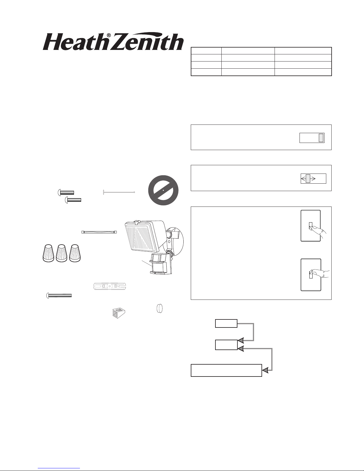
Model 5525
Features
• Turns on lighting when motion is detected.
• Automatically turns lighting off.
• Photocell keeps the lighting off during daylight hours.
• LED indicates motion was sensed (day or night).
This package includes:
Plastic Hanger
6 Screws
(3 sizes included)
1 Halogen
Lamp
Sensor
3 Wire
Connectors
Mounting Strap
Gasket
Light Control
* resets to Auto Mode at dawn.
Note: When first turned on wait about 1 1/2 minutes for
the circuitry to calibrate.
TEST
Put the ON-TIME switch on the bottom
of the sensor in the TEST position.
AUTO
Put the ON-TIME switch in the 1, 5,
or 10 minute position.
MANUAL MODE
Manual mode only works at night
because daylight returns the sensor to AUTO.
Flip the light switch off for one second then back on to toggle between
AUTO and MANUAL MODE.
Manual mode works only with the
ON-TIME switch in the 1, 5, or 10
position.
ON-TIME
10 5 1 TEST
ON-TIME
10 5 1 TEST
1 Second OFF
then...
... back on.
Mounting Bolt
Light Shield
Requirements
• The light control requires 120-volts AC.
• If you want to use Manual Mode, the control must be
wired through a switch.
• Some codes require installation by a qualified
electrician.
• This product is intended for use with the enclosed
gasket and with a junction box marked for use in wet
locations.
© 2015 HeathCo LLC 204055-02A
Mode Switch Summary
Rubber Plug
Move ON-TIME Switch to
1, 5, or 10 minutes
Flip light switch
off for one second
then back on*
* If you get confused while switching modes, turn the
power off for one minute, then back on. After the calibration time the control will be in the AUTO mode.
Page 2
INSTALLATION
CAUTION: Keep the sensor at least 1" (25 mm)
away from the bulbs.
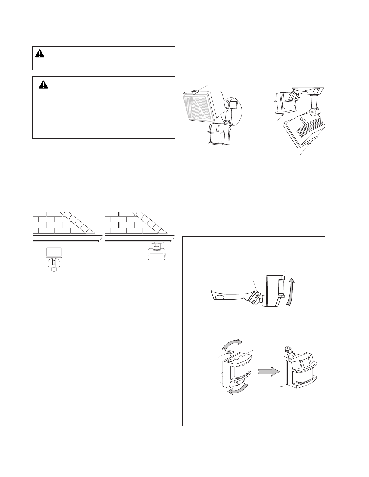
• Note the position of the various parts of the fixture for
the type of installation for your application and adjust
the lamp head and sensor as shown below.
Wall Mount Eave Mount
CAUTION: To Avoid Fire Or Burn Hazards:
• Allow fixture to cool before touching. The bulb and
the fixture operate at high temperatures.
•
Keep fixture at least 2" (51 mm) from combustible ma-
terials. Do not aim at objects closer than 3 feet (1 m).
• Use only T3, 250W (maximum) tungsten halogen
120 VAC lamps.
For easy installation, select an existing light operated
by a wall switch for replacement. IMPORTANT: Do NOT
use with dimmers or timers.
For best performance, mount the fixture about 8 feet
(2.4 m) above the ground. NOTE: If fixture is mounted
higher than 8 feet (2.4 m), aiming the sensor down will
reduce coverage distance.
Lens Retainer
Light Shield,
with opening
at this side
Lens Retainer
Before installing the light fixture under an eave, the
sensor head must be rotated as shown in the next
two steps for proper operation and to avoid the risk of
electrical shock.
IMPORTANT: For proper under-eave operation, install
light shield (included). See Light Shield Installation
for details.
For eave mount only:
1. Swing the sensor head towards the clamp screw
joint.
Wall Mount Eave Mount
NOTE: Light fixture and sensor should be mounted as
shown above when installed (depending upon type of
installation).
Controls
Clamp Screw
2. Then rotate the sensor head clockwise 180° so
the controls face down.
Controls
Light Shield
Opening
Controls
If the sensor pops out of the ball joint, loosen the
clamp screw and push the sensor back into the ball
joint. Tighten the clamp screw when done.
2
204055-02
Page 3
Bulb Installation and Replacement
CAUTION: When replacing the bulb, turn power
off and let the fixture cool.
Important: Use a clean glove or cloth when handling
the new bulb. Use isopropyl (rubbing) alcohol to clean
the bulb if it is touched with your bare hands.
NOTE: The bulb is included, but needs to be installed.
The bulb is located behind the glass cover of the
lamp head.
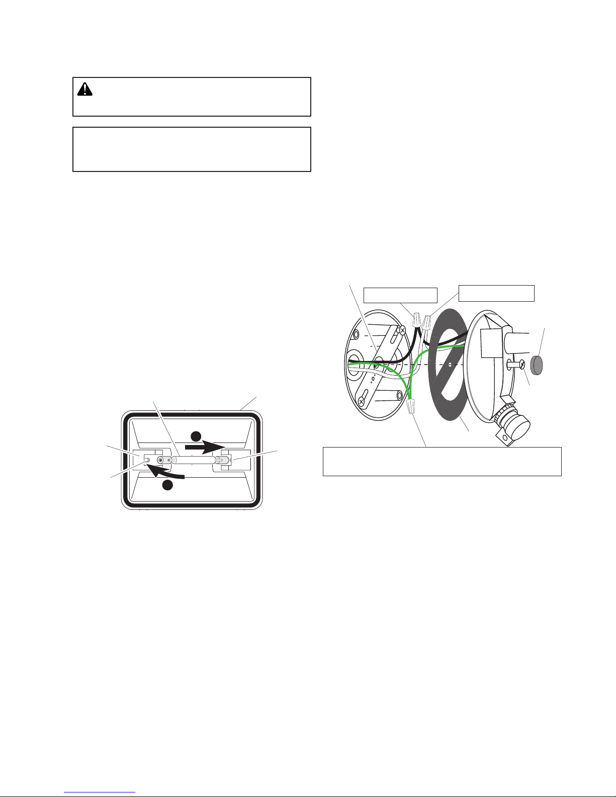
1. Remove glass cover and remove the old bulb by
pushing the bulb towards the right until the left side
of the bulb is clear of the left socket.
2. To install the bulb, place one end of the bulb on the
contact in the right socket. While pushing the bulb
against the right contact, lower the other end of the
bulb onto the contact in the left socket.
3. Spin the bulb to verify it is seated properly.
4. Re-install the glass cover.
For proper operation and safety, the light fixture must
be above the sensor and the sensor head must be
rotated so that the controls are on the bottom.
Wire the Light Control
1. Turn the power to the lighting circuit off at the
fuse or circuit breaker box.
2. Remove the existing light fixture.
3. Install mounting strap to junction box using screws
appropriate for your junction box.
4. The plastic hanger can be used to hold the fixture
while wiring. The small end of the plastic hanger
can be threaded through the hole in the center of
the cover plate. The small end then goes into one
of the slots on the mounting strap.
5. Thread all fixture wires through the large holes in
the gasket as shown.
6. Connect the junction box wires to the light fixture
wires as shown. Twist together and secure with wire
connectors.
Mounting Strap
Black to Black
White to White
Rubber
Plug
Left
Socket
Contact
Bulb Lamp Head
1
Right
Socket
2
Mounting
Bolt
Gasket
Connect any fixture ground wire(s) and the cover plate
ground screw to the junction box ground wire.
Mount the Light Control
1. Align the light control cover plate and cover plate
gasket. Secure with the mounting bolt.
2. Push the rubber plug firmly into place.
3. If a wet location junction box was not used, caulk
the wall plate mounting surface with silicone weather
sealant.
204055-02
3
Page 4
TEST AND ADJUSTMENT
1. Turn on the circuit breaker and light switch.
NOTE: Sensor has about 1 1/2 minutes warm up period
before it will detect motion. When first turned
on, wait about 1 1/2 minutes.
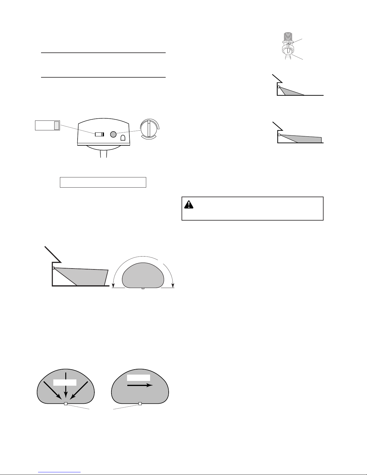
2. Turn the RANGE control to the minimum position (MIN) and the ON-TIME control to the TEST
position.
ON-TIME
10 5 1 TEST
Bottom of Sensor
Avoid aiming the control at:
• Objects that change temperature rapidly, such as
heating vents and air conditioners. These heat
sources could cause false triggering.
• Areas where pets or traffic may trigger the control.
• Nearby large, light-colored objects reflecting light
may trigger the shut-off feature. Do not point other
lights at the sensor.
8 ft.
(2.4 m)
70 ft.
(21 m)
Maximum Range Maximum
Coverage Angle
NOTE:
the sensor down will reduce coverage distance.
The detector is most sensitive to motion across its field
of view.
If fixture is mounted higher than 8 ft. (2.4 m), aiming
RANGE
MIN MAX
180°
1. Loosen the clamp screw in the
sensor ball joint and gently
rotate the sensor.
2. Walk through the coverage
area noting where you are
when the lights turn on (also,
the LED will flash several times
when motion is detected). Move
the sensor head up, down, or
sideways to change the coverage area. Keep the sensor at
least 1" (2.5 cm) away from
the lamp.
3. Adjust the RANGE as needed.
RANGE set too high may
increase false triggering.
4. Secure the sensor head
by tightening the clamp
screw. Do not overtighten
the screw.
5. Set the amount of TIME you want the lights to stay
on after motion is detected (1, 5, or 10 minutes).
WARNING - Risk of fire. Do not aim the bulbs
at a combustible surface within 3 ft. (1 m).
Aim Sensor
Down for Short
Coverage
Aim Sensor
Higher for Long
Coverage
Clamp
Screw
Ball
Joint
Light Shield Installation
If your light does not come on at dusk or turns off unexpectedly, then another light source may be activating
the daytime shutoff feature. Possible sources of light
interference are street lights, landscape lighting, other
security lights or lanterns, or an interior house light shining through a window. It could also be reflective light,
such as from a pool or light colored wall.
To install the light shield, follow these simple steps.
1. Remove protective backing from the bottom of the
light shield.
2. Position light shield over the photocell with the
opening facing away from the interfering light.
3. Press the adhesive side firmly against the photocell
to mount it permanently in place.
Motion
Sensor
Least Sensitive Most Sensitive
Motion
4
204055-02
Page 5

Light
Shield
Protective
Backing
SPECIFICATIONS
Range . . . . . . . . . . . . . Up to 70 ft. (21 m) [varies with
surrounding temperature].
Sensing Angle . . . . . . . Up to 180°
Electrical Load . . . . . . . Up to 250 Watts Maximum
Incandescent.
Power Requirements . . 120 VAC, 60 Hz
Operating Modes . . . . . TEST, AUTO and MANUAL
MODE
Time Delay . . . . . . . . . 1, 5, 10 minutes
Replacement lamp . . . . T3, 250W (or less) halogen
120 VAC
HeathCo LLC reserves the right to discontinue products
and to change specifications at any time without incurring
any obligation to incorporate new features in products
previously sold.
TROUBLESHOOTING GUIDE
SYMPTOM POSSIBLE CAUSE SOLUTION
Light will not come on. 1. Light switch is turned off.
Light comes on in daylight.
Light comes on for no
apparent reason.
Light stays on continuously.
Light flashes on and
off.
Light flashes once, then
stays off in manual
mode.
2. Lamp is loose or burned out.
3. Fuse is blown or circuit breaker is turned off.
4. Daylight turn-off is in effect.
5. Incorrect circuit wiring, if this is a new installation.
6. Light control aimed in wrong direction.
1. Light control may be installed in a relatively dark
location.
2. Light control is in TEST.
1. Light control may be sensing small animals or automobile traffic.
2. Range is set too high.
1. A lamp is positioned too close to the light control or
pointed at nearby objects that cause heat to trigger
the light control.
2. The light control may be picking up a heat source
like an air vent, dryer vent, or brightly painted, heatreflective surface.
3. Light control is in manual mode.
1. Heat or light from the lamps may be turning the light
control on and off.
2. Heat being reflected from other objects may be turning the light control on and off.
3. Light control is in the TEST mode and warming up.
4. If eave installation, light shield not installed properly.
Light control is detecting its own lights. Reposition lamp to keep area below the light control
1. Turn light switch on.
2. Check lamp and replace if burned out.
3. Replace fuse or turn circuit breaker on.
4. Recheck after dark.
5. Verify wiring is correct.
6. Re-aim light control to cover desired area.
1. The fixture is operating normally under these conditions.
2. Set control switch to 1, 5, or 10 minutes.
1. Re-aim light control.
2. Reduce range.
1. Reposition the lamp away from the light control or
nearby objects.
2. Re-aim light control. Reduce range.
3. Switch light control to AUTO.
1. Reposition the lamp away from the light control.
2. Reposition light control.
3. Flashing is normal under these conditions.
4. Install light shield according to instructions.
relatively dark.
204055-02
5
Page 6

TECHNICAL SERVICE
Please call 1-800-858-8501 (English speaking only) for assistance before returning
product to store.
If you experience a problem, follow this guide. You may also want to visit our Web site at: www.hzsupport.com.
If the problem persists, call* for assistance at 1-800-858-8501 (English speaking only), 8:00 AM to 5:00 PM CST
(M-F). You may also write* to:
HeathCo LLC
P.O. Box 90045
Bowling Green, KY 42102-9045
ATTN: Technical Service
* If contacting Technical Service, please have the following information available: Model Number, Date of Purchase, and Place of Purchase.
No Service Parts Available for this Product
Please keep your dated sales receipt, it is required for all warranty requests.
TWO YEAR LIMITED WARRANTY
This is a “Limited Warranty” which gives you specific legal rights. You may also have other rights which vary from
state to state or province to province.
For a period of two years from the date of purchase, any malfunction caused by factory defective parts or
workmanship will be corrected at no charge to you.
Not Covered - Repair service, adjustment and calibration due to misuse, abuse or negligence, light bulbs,
batteries, and other expendable items are not covered by this warranty. Unauthorized service or modification of the product or of any furnished component will void this warranty in its entirety. This warranty does
not include reimbursement for inconvenience, installation, setup time, loss of use, unauthorized service, or
return shipping charges.
This warranty covers only HeathCo LLC assembled products and is not extended to other equipment and
components that a customer uses in conjunction with our products.
THIS WARRANTY IS EXPRESSLY IN LIEU OF ALL OTHER WARRANTIES, EXPRESS OR IMPLIED,
INCLUDING ANY WARRANTY, REPRESENTATION OR CONDITION OF MERCHANT ABILITY OR THAT
THE PRODUCTS ARE FIT FOR ANY PARTICULAR PURPOSE OR USE, AND SPECIFICALLY IN LIEU OF
ALL SPECIAL, INDIRECT, INCIDENTAL, OR CONSEQUENTIAL DAMAGES.
REPAIR OR REPLACEMENT SHALL BE THE SOLE REMEDY OF THE CUSTOMER AND THERE SHALL
BE NO LIABILITY ON THE PART OF HEATHCO LLC FOR ANY SPECIAL, INDIRECT, INCIDENTAL, OR
CONSEQUENTIAL DAMAGES, INCLUDING BUT NOT LIMITED TO ANY LOSS OF BUSINESS OR PROFITS, WHETHER OR NOT FORESEEABLE. Some states or provinces do not allow the exclusion or limitation
of incidental or consequential damages, so the above limitation or exclusion may not apply to you. Please
keep your dated sales receipt, it is required for all warranty requests.
This device complies with Part 15 of the FCC Rules. Operation is subject to the following two conditions: (1) this
device may not cause harmful interference, and (2) this device must accept any interference received, including
interference that may cause undesired operation.
CAN ICES-3 (B)/NMB-3(B)
6
204055-02
Page 7

Aparato de Halógeno y
PRUEBA
AU TOM.
MODO
MANUAL
Detector de Movimiento
Modelo 5525
FUNCIONAMIENTO
Modalidad: A tiempo: Trabaja: Día Noche
Prueba
Autom.
Manual
*Se pone en Automático al amanecer.
Nota: Cuando lo prenda por primera vez espere unos
1 1/2 minutos hasta que el circuito se calibre.
5 segundas x x
1, 5 o 10 min. x
Hasta el
amanecer*
x
Características
• Prende la luz cuando detecta movimiento.
• Apaga la luz automáticamente.
•
La fotocélula mantiene la luz apagada durante el día.
• LED indica que se ha detectado movimiento (durante
el día o la noche).
Este paquete tiene:
Colgador plástico
6 tornillos
(3 dimensiones)
3 conectores
de alambre
1 Bombilla
Halógena
Protector de
lámpara
Empaquetadura
Detector
Control de luz
Para PRUEBA:
Ponga el interruptor de tiempo (ONTIME), al fondo del detector, en la
posición de prueba (TEST).
Para AUTOMATICO:
Ponga el interruptor de tiempo (ONTIME) en la posición de 1, 5 o 10
minutos.
Para MODO MANUAL:
El modo manual funciona sólo por la
noche porque la luz del día pone al
detector en modo AUTOMATICO.
Apague el interruptor por un segundo
y vuélvalo a prender.
El modo manual funciona sólo
cuando el interruptor de tiempo (ONTIME) está en la posición de 1, 5 o
10 minutos.
ON-TIME
10 5 1 TEST
ON-TIME
10 5 1 TEST
1 segundo
APAGADO
luego...
...préndalo.
Enchufe de
caucho
1 perno
Requisitos
• El control de luz requiere 120 VCA.
• Para usar el Modo Manual, conecte el control con un
interruptor.
• Algunos códigos requieren instalación por un
electricista calificado.
• Se recomienda usar este producto con el empaque
provisto y con una caja de empalme marcada para
uso en lugares húmedos.
204055-02
© 2015 HeathCo LLC 204055-02 S
Resumen de las modalidades del interruptor
Lámina de montaje
Mueva el interruptor de
tiempo (ON-TIME) a 1, 5 o 10
minutos
Apague el interruptor por
un segundo y préndalo
de nuevo*
* Si se confunde mientras cambia de fases, apague
la electricidad por un minuto y préndala de nuevo.
Después del tiempo de calibración el control estará
en fase AUTO(MATICA).
7
Page 8

INSTALACIÓN
CUIDADO: Mantenga al detector por lo menos
a 25 mm de las lámparas.
CUIDADO: Para evitar los peligros de incen-
dio o quemazón:
• Deje que el elemento se enfríe antes de tocarlo. La bombilla y el elemento funcionan a altas temperaturas.
• Mantenga al elemento por lo menos a 51 mm de
los materiales combustibles. No lo apunte hacia
objetos que estén más cerca de 1 m.
• Use sólo lámparas halógenas de tungsteno de T3,
120 VCA y de 250 vatios máximo.
Para una fácil instalación escoja una luz con un
interruptor de pared. IMPORTANTE: No lo use con
temporizadores o atenuadores de luz.
Para un mejor funcionamiento, instale el aparato a casi
2.4 m del suelo. NOTA: Si el aparato está instalado a
más de 8 pies (2,4 m), si se apunta el detector hacia
abajo se reducirá la distancia de cobertura.
Antes de instalar la lámpara bajo un alero, la cabeza
del sensor debe rotarse como se muestra en los dos
pasos siguientes para la correcta operación y evitar el
riesgo de descarga eléctrica.
IMPORTANTE: Para un funcionamiento correcto
debajo del alero, instale el protector de la luz (incluido). Vea Instalación del Protector de la luz para
más detalles.
Sólo para montaje eléctrico:
1. Gire la cabeza del detector hacia la unión del
tornillo sujetador.
Tornillo Sujetador
2. Entonces gire la cabeza del detector hacia la
derecha por 180° hasta que los controles miren
hacia abajo.
Controles
Montaje en pared Montaje en alero
NOTA: La lámpara y el sensor debe montarse como
se indica arriba, una vez instalado (según el tipo de
instalación).
• Note la posición de las varias partes del aparato para
el tipo de instalación que necesita su aplicación y
ajuste el cabezal de la lámpara y el detector como
se muestra abajo.
Montaje en pared Montaje en alero
Retenedor de la
placa translúcida
Controles
Apertura del
protector de
lámpara
Controles
Si el detector se sale de la unión esférica, afloje el
tornillo sujetador y empuje el detector hacia dentro
de la unión esférica. Apriete el tornillo sujetador
cuando termine.
Protector de
lámpara con
apertura en
este lado
Retenedor de la placa translúcida
8
204055-02
Page 9

Instalación y Cambio de Bombilla
CUIDADO: Cuando cambie la bombilla, apague
la energía y deje que el aparato se enfríe.
Importante: Cuando manipule la bombilla nueva use
un guante o un paño que estén limpios. Use alcohol
isopropílico (frotando) para limpiar la bombilla si ha
sido tocada con manos desprotegidas.
NOTA: La bombilla se incluyen pero deben ser
instaladas. La bombilla se encuentran detrás de la
cobertura de vidrio de cada cabezal de lámpara.
1. Quite la cubierta de vidrio y quite la bombilla vieja
empujándola hacia la derecha hasta que el lado
izquierdo de la bombilla se salga del enchufe izquierdo.
2. Para instalar la bombilla, ponga un extremo de la
bombilla sobre el contacto del enchufe derecho.
Mientras empuja la bombilla contra el contacto
derecho, baje el otro extremo de la bombilla sobre
el contacto del enchufe izquierdo.
3. Gire la bombilla para verificar que esté correctamente asentada.
4. Coloque la cubierta de vidrio.
Para un funcionamiento apropiado y seguro, el
aparato de luz (lámpara) debe estar encima del
sensor y a la cabeza del sensor se la debe girar
de modo que los controles queden en la parte
inferior.
Bombilla
Cabezal de
la lámpara
Conecte el Control de Luz
1. Apague la energía en el fusible o cortacircuitos.
2. Quite el aparato de luz existente.
3. Instale la lámina de montaje a la caja de empalme usando tornillos apropiados para la caja de empalme.
4. Se puede usar el colgador plástico para sostener
el aparato mientras se instala el cableado. El extremo pequeño del colgador se puede pasar por
el agujero en el centro de la placa cubertora. El
extremo pequeño va luego dentro de las ranuras
de la lámina de montaje.
5. Pase todos los cables del aparato por los agujeros
grandes del empaque, como se muestra.
6. Conecte los cables de la caja de empalme con
los cables del aparato de luz, como se muestra.
Tuérazalos juntos y asegúrelos con un conector
de cables.
Negro a Negro
lámina de
montaje
Empaquetadura
Conecte los alambres del aparato, propuestos
para conexión a tierra, a la conexión a tierra de
la caja de enpalme.
Blanco a Blanco
Enchufe de
Caucho
Perno de
montaje
Enchufe
izquierdo
Contacto
204055-02
1
2
Enchufe
derecho
Instale el Control de Luz
1. Ponga el perno de montaje a través del frente de
la tapa de la caja de empalme. Empuje el agujero
pequeño de la empaquetadura sobre el tornillo de
montaje.
2. Empuje el tapón de caucho firmemente hasta que
encaje.
3. Si no se usó una caja de empalme en un lugar
húmedo, calafatee la superficie de montaje de la
placa de la pared con un sellador de silicona contra
la intemperie.
9
Page 10

PRUEBA Y AJUSTE
1. Prenda el cortacircuitos y el interruptor de luz.
NOTA: El detector tiene un período de cerca de 1 1/2
minutos de calentamiento antes de detectar
movimiento. Cuando lo prenda por primera
vez, espere 1 1/2 minutos.
2. Gire el control RANGE a la posición mínima (MIN)
y el control ON-TIME a la posición TEST.
ON-TIME
RANGE
El detector es menos sensible del movimiento que se
dirige hacia él.
Movimiento
Detector
Movimiento
Lo menos sensible Lo más sensible
10 5 1 TEST
MIN MAX
Parte de abajo del detector
Evite apuntar el control hacia:
• Objetos que cambien rápidamente de temperatura
tales como ductos de calefacción y acondiciona-
dores de aire. Estas fuentes de calor pueden causar
falsas alarmas.
• Áreas donde animales domésticos o el tráfico
puedan activar el control.
• Los objetos grandes cercanos y de colores res-
plandecientes que reflejan la luz del día pueden
hacer que el detector se apague. No apunte otras
luces hacia el detector.
8 pies
(2.4 m)
70 pies
(21 m)
180°
3. Afloje el tornillo sujetador en la
unión esférica y gire despacio
el detector.
4. Camine por el área a protegerse y dése cuenta dónde
está cuando se prende la luz
(además, el LED destellará
varias veces cuando se detecta
movimiento). Mueva la cabeza
del detector hacia arriba, hacia
abajo o hacia los lados para
cambiar el área de protección.
Mantenga al detector por
lo menos a 1 pulgada (2.5
cm) de las lámparas.
5. Fije la sensibilidad (RANGE)
como necesite. Demasiada
sensibilidad puede aumentar
las falsas alarmas.
6. Asegure la puntería de la ca-
beza del detector ajustando el tornillo sujetador.
No lo apriete demasiado.
7. Fije el período de tiempo (ON-TIME) que la luz debe
quedarse prendida después de detectar movimiento
(1, 5 o 10 minutos).
ADVERTENCIA: Riesgo de incendio. No apunte
las lámparas a superficies combustibles dentro
de un 3 pies (1 m).
abajo para poca
mayor cobertura
Tornillo
Sujetador
Unión
Esférica
Apunte el
detector hacia
cobertura
Apunte el
detector más
arriba para
Alcance Máximo Angulo de
Cobertura Máxima
NOTA: Si el aparato está instalado a más de 8 pies (2,4
m), si se apunta el detector hacia abajo se reducirá la
distancia de cobertura.
10
204055-02
Page 11

Instalación del Protector de Luz
Si la luz no se prende al anochecer o se apaga
inesperadamente, otra fuente de luz puede estar
activando el elemento de apague del día. Las posibles fuentes de interferencia de luz son las luces de
la calle, el alumbrado de los jardines, otras luces de
seguridad o faroles, o la luz interior de una casa que
brilla a través de una ventana. Puede también ser
una luz reflectante, como el de una piscina o pared
de color brillante.
Para instalar el protector de la luz, siga estos pasos
sencillos.
1. Quite el protector adhesivo de la parte inferior del
protector de la luz.
2. Ponga el protector de la luz sobre la fotocélula con
su abertura hacia el otro lado de la luz de interferencia.
3. Presione firmemente el lado con la cinta adhesiva
contra la fotocélula para montarla permanentemente
en su sitio.
SPECIFICATIONS
Alcance . . . . . . . . . . . . . Hasta 21 m (varía con la
temperatura del medio am-
biente).
Angulo de detección . . . Hasta 180°
Carga Eléctrica . . . . . . . Hasta 250 Vatios Máximo de
luz incandescente halógeno
Requisitos de energía . . 120 VCA, 60 Hz
Fases de Operación . . . PRUEBA, AUTOMATICO, y
MODO MANUAL
Retardo de Tiempo . . . . Ajustable de 1, 5, o 10 minu-
tos
Bombilla de repuesto . . . T halógena de dos clavijas
de 120 VCA y de 250W
HeathCo LLC se reserva el derecho de descontinuar
productos y de cambiar especificaciones a cualquier
momento sin incurrir en ninguna obligación de tener
que incorporar nuevas características en los productos
vendidos con anterioridad.
Protector
de la luz
Protector
adhesivo
204055-02
11
Page 12

GUIA DE INVESTIGACION DE AVERIAS
SÍNTOMA POSIBLE CAUSA SOLUCIÓN
La luz no se enciende. 1. El interruptor de luz está apagado.
La luz se prende durante
el día.
La luz se prende sin
ninguna razón aparente.
La luz se queda prendida
continuamente.
La luz se prende y se
apaga.
La luz se prende una
vez y luego permanece
apagada en la fase
Manual.
2. El faro está flojo o quemado.
3. El fusible está quemado o el cortacircuitos está
apagado.
4. La desconexión de luz del día está en efecto.
5. Alambrado incorrecto, si ésta es una nueva instalación.
6. El control de luz está apuntando en dirección incorrecta.
1. El control de luz puede estar instalado en un lugar
relativamente oscuro.
2. El control de luz está en fase de Prueba.
1. El control de luz puede estar detectando animales
pequeños o el trásito de automóviles.
2. El margen está puesto muy alto.
1. El faro está muy cerca del control de luz o apuntando
a objetos cercanos que generan calor y activan el
control de luz.
2. El c ontrol de luz está apuntando hacia una fuente de calor
tal como un conducto de aire, de secadora o hacia una
superficie con pintura brillante y que refleja el calor.
3. El control de luz está en el modo manual.
1. El calor o la luz de los faros puede estar encendiendo
y apagando el control de luz.
2. El calor reflejado por otros objetos puede estar
encendiendo y apagando el control de luz.
3. El control de luz está en fase de Prueba y calentándose.
4. Si es una conexión de alero, el protector de lámpara
no está instalado correctamente.
El control de luz está detectando su propia luz. Reubique los faros para mantener relativamente obscura
1. Encienda el interruptor de luz.
2. Revise el faro y cambie si está quemado.
3. Cambie el fusible encienda el disyuntor.
4. Compruébelo cuando comience la obscuridad.
5. Verifique que el cableado esté correcto.
6. Vuelva a apuntar el control de luz para que cubra el
área deseada.
1. El aparato está funcionando normalmente bajo estas
condiciones.
2. Fije el interruptor de control a 1, 5 o 10 minutos.
1. Reapunte el control de luz.
2. Apague el Aumento de Distancia.
1. Reubique el faro lejos del control de luz o de objetos
cercanos.
2. Reapunte el control de luz. Apague el Aumento de
Distancia.
3. Cambie el control de luz a AUTO.
1. Reubique el faro lejos del control de luz.
2. Reubique el control de luz.
3. El prenderse y apagarse es normal bajo estas condiciones.
4. Instale el protector de lámpara de acuerdo a las
instrucciones.
la zona debajo de la lámpara.
12
204055-02
Page 13

SERVICIO TÉCNICO
Favor de llamar al 1-800-858-8501 (sólo para hablar en inglés) para pedir ayuda antes
de devolver el producto a la tienda.
Si tiene algún problema, siga esta guía. Usted puede también visitar nuestro sitio Web: www.hzsupport.com.
Si el problema continúa, llame al 1-800-858-8501 (sólo para hablar en inglés), de 8:00 AM a 5:00 PM CST (LV). Usted puede también escribir a:
HeathCo LLC
P.O. Box 90045
Bowling Green, KY 42102-9045
ATTN: Technical Service (Servicio Técnico)
* Si se llama al Servicio Técnico, por favor tener lista la siguiente información: Número de Modelo, Fecha de
compra y Lugar de compra.
No hay piezas de servicio disponibles para este producto.
Por favor guarde su recibo de venta fechado; se lo requiere para cualquier solicitud de garantía.
GARANTÍA LIMITADA A 2 AÑOS
Esta es una “Garantía Limitada” que le da a Ud. derechos legales específicos. Usted puede también tener
otros derechos que varían de estado a estado o de provincia a provincia.
Por un período de 2 años desde la fecha de compra, cualquier mal funcionamiento ocasionado por partes
defectuosas de fábrica o mano de obra será corregido sin cargo para Ud.
No cubierto - Servicio de reparación, ajuste y calibración debido al mal uso, abuso o negligencia, bombillas, baterías, u otras partes fungibles no están cubiertas por esta garantía. Los Servicios no autorizados
o modificaciones del producto o de cualquier componente que se provee invalidarán esta garantía en su
totalidad. Esta garantía no incluye reembolso por inconveniencia, instalación, tiempo de instalación, perdida
de uso, servicio no autorizado, o costos de transporte de retorno.
Esta garantía cubre solamente los productos ensamblados por HeathCo LLC y no se extiende a otros equipos o componentes que el consumidor usa junto con nuestros productos.
ESTA GARANTÍA ESTÁ EXPRESAMENTE EN LUGAR DE OTRAS GARANTÍAS, EXPRESADAS O SOBREENTENDIDAS, INCLUYENDO CUALQUIER GARANTÍA, REPRESENTACIÓN O CONDICIÓN DE
COMERCIABILIDAD O QUE LOS PRODUCTOS SE ADAPTEN PARA CUALQUIER PROPÓSITO O USO
EN PARTICULAR, Y ESPECIFICAMENTE EN LUGAR DE TODOS LOS DAÑOS ESPECIALES, INDIRECTOS, INCIDENTALES Y CONSECUENTES.
LA REPARACIÓN O EL REEMPLAZO DEBERÍA SER LA ÚNICA SOLUCIÓN DEL CLIENTE Y NO HABRÁ
RESPONSABILIDAD POR PARTE DE HEATHCO LLC POR CUALQUIER DAÑO ESPECIAL, INDIRECTO,
INCIDENTAL O CONSECUENTE, INCLUIDOS PERO NO LIMITADOS A CUALQUIER PÉRDIDA DE NEGOCIO O GANACIAS SEAN O NO PREVISIBLES. Algunos estados o provincias no permiten la exclusión
o limitación de daños incidentales o consecuentes, de modo que la limitación o exclusión arriba indicada
puede que no se aplique a Ud. Por favor guarde su recibo de venta fechado; se lo requiere para cual-
quier solicitud de garantía.
Este aparato cumple con la Parte 15 de las Reglas de la FCC. La operación está sujeta a las dos siguientes
condiciones: (1) este aparato no puede causar interferencias perjudiciales y (2) este aparato debe aceptar
cualquier interferencia recibida, incluyendo una interferencia que pueda causar un funcionamiento indeseado.
CAN ICES-3 (B)/NMB-3(B)
204055-02
13
Page 14

Luminaire-détecteur de
mouvement à halogène
Modèle 5525
Exigences
• La commande d’éclairage nécessite une alimentation
de 120 V c.a.
• Pour utiliser la priorité manuelle, raccorder la commande à un interrupteur.
• Certains codes de bâtiment locaux peuvent exi-
ger que l’installation soit faite par un électricien
qualifié.
• Ce produit est conçu pour être utilisé avec une boîte
de jonction portant une indication d'utilisation possible
en milieu humide.
Caractéristiques
• Allume l'appareil d'éclairage lorsqu'un mouvement
est détecté.
• Éteint automatiquement l'éclairage.
• Photocellule qui maintient l'éclairage éteint pendant
la période de lumière du jour.
• La DEL indique qu'un mouvement a été détecté (jour
ou nuit).
Cet emballage comprend:
Bouchon de
Caoutchouc
Crochet en plastique
6 vis incluses
(3 formats)
Détecteur
Garniture
de joint
FONCTIONNEMENT
Mode: Temps en circuit : En fonction : jour nuit
Essai
Auto
Manuel
* Revient au mode automatique au lever du soleil.
Note: Après mise en circuit, attendre enfiron
Amener en position d’essai (TEST)
l’interrupteur de temps en circuit
(ON-TIME) du bas du détecteur.
Amener l’interrupteur de temps en
circuit (ON-TIME) à la position correspondant à 1, 5 ou 10 minutes.
5 Secondes x x
1, 5 ou 10 Min x
au choix, amanecer* x
1 1/2 minute pour que l’étalonnage du circuit soit
complété.
ESSAI
ON-TIME
10 5 1 TEST
AUTOMATIQUE
ON-TIME
10 5 1 TEST
3 serre-fils
Vis de montage
1 Lampe à
halogène
© 2015 HeathCo LLC 204055-02 F
Écran de protection
Bride de montage
Commande
d’éclairage
PRIORITÉ MANUELLE
Le mode manuel ne fonctionne
que la nuit parce que la lumière
du jour remet le capteur en mode
AUTO.
Mettre l’interrupteur hors circuit
pendant une seconde, plus en
circuit pour alterner entre les
modes AUTO et MANUEL.
Le mode manuel ne fonctionne
qu’avec l’interrupteur ON-TIME,
aux positions 1, 5 ou 10.
14
hors circuit
pendant 1
seconde,
puis ...
... à nouveau
en circuit
204055-02
Page 15

Résumé du mode de commutation
PRIORITÉ MANUELLE
AUTO
TEST
Placer l’interrupteur ON-
TIME à 1, 5 ou 10 minutes
• Noter l’emplacement des diverses pièces du luminaire
pour le type d’installation qui vous concerne et régler
la tête de la lampe et le détecteur comme illustré cidessous.
Mettre l’interrupteur
hors circuit pendant
une seconde, puis le
remettre en circuit*
* Si vous ne savez plus dans quel mode se trouve l’ap-
pareil, couper l’alimentation pendant une minute puis
la rétablir. Après le temps d’étalonnage, la commande
reviendra au mode AUTO.
INSTALLATION
AVERTISSEMENT: Ne pas permettre au
détecteur d’être à moins de 25 mm des lampes.
AVERTISSEMENT: Pour éviter les risques
de brûlure ou d'incendie
• Laisser l’appareil refroidir avant de le toucher.
L’ampoule et l’appareil fonctionnent à haute température.
• Garder l’appareil à au moins 51 mm des matériaux
combustibles. Ne pas pointer vers des objets à moins
de 1 m.
• Utiliser seulement des ampoules halogènes à deux
broches T3 au tungstène, de 250 watts maximum,
120 Vca.
Montage mural Montage sous
avant-toit
Fixation de lentille
Écran de
protection avec
ouverture de
ce côté
Fixation de lentille
Avant d’installer le luminaire sous l’avant-toit, le
capteur doit être tourné comme démontré dans les
deux étapes suivantes pour une opération fonctionelle
et pour éviter le risque de choc électrique.
IMPORTANT : Pour un bon fonctionnement sous
avant-toit, installez un pare-lumière (inclus). Voir
Installation de Pare-lumière pour des détails.
Pour montage sous avant-toit seulement:
1. Faire pivoter la tête du détecteur en direction du
joint à vis de blocage.
Pour faciliter l’installation, choisir un appareil d’éclairage
devant être remplacé et qui est déjà commandé par un
interrupteur. IMPORTANT : Ne PAS utiliser avec des
gradateurs de lumière ou des minuteries.
Pour assurer un rendement optimum, monter le luminaire
à environ 2,4 m au-dessus du sol. NOTE : Lorsque le
luminaire est installé à une hauteur supérieure à 8 pi
(2,4 m), le fait de diriger le détecteur vers le bas réduit
la portée de la couverture.
Montage mural Montage sous
avant-toit
NOTE : Le luminaire et capteur devraient être montés
comme montré ci-dessus au cours de l’installation (selon
le type d’installation.)
204055-02
Vis De Blocage
Commandes
2. Puis faire pivoter le détecteur sur 180° de façon
que les commandes soient tournées vers le bas.
Commandes
Ouverture
de l’écran de
protection
Commandes
Si le détecteur sort de la rotule, desserrer la vis de
blocage et ré-insérer le détecteur dans la rotule et
resserrer la vis.
15
Page 16

Installation et Remplacement de
L’ampoule
AVERTISSEMENT : Avant de remplacer une
ampoule, couper l’alimentation et attendre que
l’appareil refroidisse.
Important : Utiliser un gant ou un chiffon propre
pour manipuler la nouvelle lampe. Utiliser de l’alcool
isopropylique (à friction) pour nettoyer la lampe si
vous y touchez avec vos doigts.
NOTE : Le ampoule sont incluses, mais elles doivent
être installées. Le ampoule se trouvent derrière le
couvercle en verre de chaque tête de lampe.
1. Enlever le couvercle de verre et retirer la vieille
ampoule en la faisant glisser vers la droite jusqu’à
ce que le bout gauche de l’ampoule se dégage de
la douille gauche.
2. Pour installer l’ampoule, placez une extrémité de
l’ampoule sur le contact dans la douille droite. Tout en
poussant l’ampoule contre le contact droit, baissez
l’autre extrémité de l’ampoule sur le contact dans
la douille gauche.
3. Tournez l’ampoule pour vérifier qu’elle est installée
correctement.
4. Replacer le couvercle de verre.
Pour fonctionner correctement et sécuritairement,
l’appareil d’éclairage doit être au-dessus du
détecteur et la tête du détecteur doit être tournée
de manière que les commandes soient en bas.
Câblage de la Commande D’Éclairage
1. Couper l’alimentation du circuit d’éclairage au
fusible ou au disjoncteur.
2. Enlever l’appareil d’éclairage existant.
3. Installer la bride de montage sur la boîte de jonction
avec les vis appropriées.
4. Le crochet en plastique peut peut servir à supporter le
luminaire pendant le câblage. Le petit bout du crochet
en plastique peut être inséré dans le trou au centre de
la plaque de couverture. Ensuite, le petit bout est inséré
dans une des fentes de la barre de montage.
5. Faire passer les fils de l’appareil d’éclairage par les
grosses ouvertures de la garniture, comme montré.
6. Raccorder les fils de la boîte de jonction aux fils de
l’appareil d’éclairage. Les torsader ensemble et les
fixer avec un serre-fils.
noir / noir
lámina de
montaje
Raccorder le(s) fil(s) de terre du luminaire et la
vis de terre de la plaque de garde au fil de terre
de la boîte de jonction.
blanc /blanc
Bouchon de
Caoutchouc
Vis de
montage
Garniture de Joint
Douille de
Gauche
Contact
Ampoule Tête de Lampe
1
Douille de
Droite
2
Montage de la Commande D’Éclairage
1. Insérer la vis de montage dans le trou du couvercle
de la boîte de jonction. Pousser le petit trou de la
garniture sur la vis de montage.
2. Poussez le bouchon de caoutchouc fermement en
place.
3. Si le boîtier n'est pas étanche aux intempéries,
calfeutrer la plaque murale et la surface de montage
avec un scellant silicone.
16
204055-02
Page 17

ESSAIS ET RÉGLAGES
1. Mettre en circuit le disjoncteur et l’interrupteur
d’éclairage.
NOTE: Le capteur doit se réchauffer 1 1/2 minute avant
de pouvoir détecter le mouvement. Lorsque
l’appareil est mis en circuit, attendre 1 1/2
minute.
2. Placez la commande RANGE à sa position minimale
(MIN) et la commande ON-TIME à la positon
TEST.
Le détecteur est moins sensible au mouvement dans
sa direction.
Mouvement
Détecteur
Mouvement
Le moins sensible Le plus sensible
ON-TIME
10 5 1 TEST
RANGE
MIN MAX
Bas du détecteur
Éviter de pointer l’appareil:
•
en direction d'objets dont la température change rapidement,
tels que des bouches d'air chaud et des climatiseurs.
De telles sources de chaleur peuvent provoquer des déclenchements intempestifs.
•
vers des endroits où des animaux, des véhicules ou des
passants peuvent déclencher la commande.
•
sur de grands objets clairs à proximité qui réfléchissent
la lumière du jour et risquent de déclencher le dispositif
d'arrêt. Ne pas pointer d’autres appareils d’éclairage vers
le détecteur.
3. Desserrer la vis de blocage
de la rotule et faire pivoter le
détecteur pour pointer.
4. Marcher dans la zone de couverture et noter à quel endroit
l’éclairage se déclenche (de
plus, le voyant à DEL clignote
à plusieurs reprises lors de la
détection d’un mouvement).
Déplacer la tête du détecteur
vers le haut, le bas ou le côté
pour modifier la zone de couverture. Ne pas permettre au
détecteur d’être à moins de
25 mm des lampes.
5. Régler la sensibilité (RANGE)
selon les besoins. Une trop
grande sensibilité pourrait
causer des déclenchements
intempestifs.
6. Fixer la tête du détecteur en
position en serrant la vis de
blocage. Éviter de trop serrer la vis.
7. Placer l’interrupteur ON-TIME à 1, 5 ou 10
minutes.
Pointer le détec-
teur vers le bas
pour réduire la
Pointer le détecteur vers le haut
pour augmenter
la couverture
Vis de
blocage
Rotule
couverture
2.4 m
21 m
Portée maximale Angle de
couverture maximale
NOTE : Lorsque le luminaire est installé à une hauteur
supérieure à 8 pi (2,4 m), le fait de diriger le détecteur
vers le bas réduit la portée de la couverture.
204055-02
180°
AVERTISSEMENT - Risque d’incendie ! Ne pas
pointer les lampes vers une surface combustible
située à moins de 1 mètre.
17
Page 18

Installation de Pare-Lumière
Si votre lampe ne s’allume pas au crépuscule ou s’éteint
de façon inattendue, alors une autre source de lumière
peut avoir activé la fonction d’arrêt durant la journée.
Des sources possibles d’interférence de lumière sont
des lumières de rue, des éclairages paysagers, des
éclairages sécuritaires ou des lanternes, ou une lumière
intérieure de maison brillant à travers une fenêtre. Cela
pourrait également être une lumière réfléchie, comme
de la piscine ou d’un mur à couleur claire.
Suivez les étapes simples ci-dessous pour installer le
pare-lumière.
1. Retirez les bandes de protection du dessous du
pare-lumière.
2. Positionnez le pare-lumière sur la cellule photoélectrique avec l’ouverture orientée loin de la lumière
qui interfère.
3. Appuyez sur le côté adhésif fermement contre la
cellule photoélectrique pour la mettre en place de
façon permanente.
FICHE TECHNIQUE
Portée . . . . . . . . . . . . . . . Jusqu’à 21 m (varie selon la
température environnante)
Angle de détection . . . . . . Jusqu’à 180˚
Charge électrique . . . . . . Jusqu’à 250 Watts Maximum,
halogène
Courant requis . . . . . . . . . 120 V c.a., 60 Hz.
Modes de
fonctionnement . . . . . . . . Essai, automatique et prior ité
manuelle
Minuterie . . . . . . . . . . . . . 1, 5 ou 10 minutes
Ampoule de
remplacement . . . . . . . . . Halogène à deux broches,
T3 de 250 watts, 120 Vca
HeathCo LLC se réserve le droit d’abandonner tout
produit et d’en changer les spécifications, en tout temps
et sans contracter quelque obligation que ce soit quant
à l’incorporation de nouvelles caractéristiques aux
produits déjà vendus.
Pare-Lumière
Bande de
Protection
18
204055-02
Page 19

GUIDE DE DÉPANNAGE
SYMPTÔME CAUSE POSSIBLE SOLUTION
L’éclairage ne s’allume
pas.
L’éclairage s’allume en
plein jour.
L’éclairage s’allume
sans raison apparente.
L’éclairage reste allumé
continuellement.
L’éclairage clignote. 1. La chaleur ou la lumière des projecteurs active et
L’éclairage clignote une
fois, puis reste éteint en
mode manuel.
1. L’interrupteur d’éclairage est hors tension.
2. Le projecteur n’est pas bien vissé ou est grillé.
3. Le fusible a sauté ou le disjoncteur a été déclenché.
4. Le dispositif de coupure pendant le jour fonctionne.
5. Mauvais câblage du circuit, dans le cas d’une nouvelle
installation.
6. La commande d’éclairage est orientée dans la mauvaise direction.
1. La commande peut être installée dans un endroit
relativement sombre.
2. La commande est en mode TEST.
1. La commande peut détecter de petits animaux ou
la circulation automobile.
2. La portée est trop élevée.
1. L’un des projecteurs est placé trop près de la commande ou est orienté vers un objet à proximité, dont
la chaleur entraîne le déclenchement de l’appareil.
2. La commande d’éclairage est pointée vers une source
de chaleur comme un évent, une sortie de sécheuse,
ou une surface claire qui réfléchit la chaleur.
3. La commande d’éclairage est en mode manuel.
désactive l’éclairage.
2. La chaleur réfléchie par des objets active et désactive
l’éclairage.
3. La commande est en mode test et se réchauffe.
4. Pour une installation sous avant-toit, l'écran de
protection n'est pas installé correctement.
La commande d’éclairage détecte sa propre lumière. Déplacez le projecteur de façon à conserver la zone
1. Mettre l’interrupteur sous tension.
2. Vérifiez le projecteur et remplacez-le s’il est grillé.
3. Remplacer le fusible ou réenclencher le disjoncteur.
4. Vérifiez à nouveau à la noirceur.
5. S’assurer que le câblage est approprié.
6. Modifiez l’orientation de la commande afin de couvrir
la zone souhaitée.
1. Le luminaire fonctionne normalement dans de telles
conditions.
2. Réglez le commutateur de commande à 1, 5 ou 10
minutes.
1. Modifiez l’orientation de la commande.
2. Réduisez la portée.
1. Modifiez l’orientation du projecteur de sorte qu’il ne
soit pas dirigé vers la commande ni vers un objet à
proximité.
2. Modifiez l’orientation de la commande. Réduisez la
portée.
3. Faites passer le commutateur à la position AUTO.
1. Modifiez l’orientation du projecteur de sorte qu’il ne
soit pas dirigé vers la commande.
2. Déplacez la commande.
3. Le clignotement est normal dans ces conditions.
4. Installer l'écran de protection selon les directives.
située sous la commande dans une relative noirceur.
204055-02
19
Page 20

SERVICE TECHNIQUE
Veuillez faire le 1 800 858-8501 (service en anglais seulement) pour obtenir de l’aide
avant de retourner l’article au magasin.
En cas de problème, suivez ce guide. Vous pouvez aussi visiter notre site Web à www.hzsupport.com. Si le
problème persiste, composez* le 1 800 858-8501 (service en anglais seulement), entre 8 h 00 et 17 h 00, HNC,
du lundi au vendredi. Vous pouvez aussi écrire au :
HeathCo LLC
P.O. Box 90045
Bowling Green, KY 42102-9045
ATTN: Technical Service (Service technique)
* Lors d’un appel au service technique, veuillez avoir les renseignements suivants à portée de main : numéro
du modèle, date d’achat et endroit de l’achat.
Aucune pièce de rechange n’est disponible pour ce produit.
Veuillez conserver le reçu portant la date d'achat; vous en aurez besoin pour toutes vos demandes liées
à la garantie.
GARANTIE LIMITÉE DE 2 ANS
Il s’agit d’une « Garantie limitée » qui vous confère des droits juridiques spécifiques. Vous pouvez également
jouir d’autres droits, variables d’une province à l’autre.
Pendant une période de 2 ans à compter de la date d’achat, toute anomalie de fonctionnement imputable
à un vice de matériau ou de main-d’oeuvre sera corrigée gratuitement.
Exclusions de la garantie - Réparations, réglage et calibrage dus à une mauvaise utilisation, un mauvais
traitement ou à la négligence. Les ampoules, les piles et des autres articles non durables ne sont pas
couverts par cette garantie. Le service non autorisé ou la modification du produit ou d’un ou l’autre de ses
composants fournis invalidera totalement la présente garantie. Cette garantie n'inclut pas le remboursement
pour le dérangement, l'installation, le réglage, la perte d'utilisation, le service non autorisé ou les frais d'expédition pour le renvoi de la marchandise.
La garantie ne couvre que les produits assemblés HeathCo LLC et ne s’étend pas aux autres équipements
et composants que le client pourrait utiliser conjointement avec nos produits.
CETTE GARANTIE TIENT EXPRESSÉMENT LIEU DE TOUTES AUTRES GARANTIES, EXPLICITES
OU IMPLICITES, Y COMPRIS DE TOUTE GARANTIE DE REPRÉSENTATION OU DE CONDITION DE
CONVENANCE À LA COMMERCIALISATION OU À L’EFFET QUE LES PRODUITS CONVIENNENT À UN
BUT OU À UNE UTILISATION PARTICULIÈRE, ET SPÉCIFIQUEMENT DE TOUS DOMMAGES SPÉCIAUX,
DIRECTS, INDIRECTS OU SECONDAIRES.
LE REMPLACEMENT OU LA RÉPARATION CONSTITUENT LE SEUL RECOURS DU CLIENT ET HEATHCO LLC NE POURRA ÊTRE TENUE RESPONSABLE DE TOUS DOMMAGES SPÉCIAUX, DIRECTS,
INDIRECTS OU SECONDAIRES, Y COMPRIS, SANS S’Y LIMITER, LES PERTES COMMERCIALES ET
PERTES DE PROFIT, QU’ELLES SOIENT PRÉVISIBLES OU NON. Certaines provinces n’autorisent pas
l’exclusion ou la limitation des dommages indirects ou secondaires, et la limitation ou l’exclusion ci-dessus
pourrait ne pas s’appliquer à vous. Veuillez conserver le reçu portant la date d'achat; vous en aurez
besoin pour toutes vos demandes liées à la garantie.
Ce dispositif est conforme à la partie numéro 15 des règlements de la FCC. Son fonctionnement est soumis
aux deux conditions suivantes : (1) cet appareil ne doit pas causer d’interférences nuisibles et (2) cet appareil
doit accepter toute interférence reçue, y compris les interférences qui peuvent perturber son fonctionnement.
CAN ICES-3 (B)/NMB-3(B)
20
204055-02
 Loading...