

Page 1
HOM rev. new
Heath of the Month #097 - SA_2040 Antenna Tuner
Heathkit of the Month (HotM) #97:
by Bob Eckweiler, AF6C
AMATEUR RADIO - SWL
Heathkit SA-2040
Antenna Tuner
Introduction:
In the second half of 1979 Heathkit released
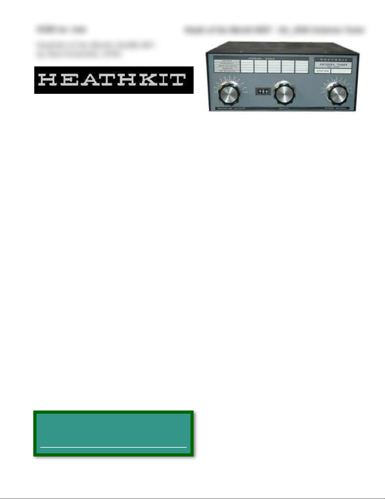
the SA-2040, a no-frills, full legal-limit, antenna tuner (Figure 1). Heath’s previous antenna tuner, the AC-11 first appeared in a
Heathkit ad in the September 1953 issue of
Radio News. The AC-1 continued to be sold
until the AT-1 transmitter was replaced by
the DX-20 HF CW transmitter in late 1956.
In the 1950s a revolution in ham equipment
began. The new rugged 6146 transmitting
tube became popular along with the pi-network output circuit designed for 50 - 75Ω
coaxial cable. Coax became the feedline of
choice due to its ease of use, and 50 and 75Ω
resonant antennas became very popular. A
well designed pi-network could tune a load
with an SWR of up to 3 to 1 allowing reasonable bandwidth around the resonant frequency. The average ham shack no longer
needed an antenna tuner. For those still using non-resonant wire antennas the venerable
E.F. Johnson Matchbox tuner line was widely
available. Over this period few antenna
tuners were marketed in the ham magazines,
though construction articles appeared occa-
sionally, and many users of wire antennas
home-brewed their tuners. In the 70’s, as
newer radios came on the market, many using
less rugged TV sweep tubes and others using
easily damaged RF power transistors with
their broad-band output coupling, antenna
tuners quickly entered back into the vogue.
Heathkit reentered the antenna tuner market with the SA-2040 antenna tuner. The
SA-2040 originally sold for $149.95, a price it
held for about two years during an inflationary period. By the fall of 1981 the price rose
to $154.95 and by the winter of 1982/1983 it
reached $169.95. It was no longer offered in
the fall 1983 catalog.
Heathkit offered two other full legal-limit
antenna tuners, the SA-2060 (followed by an
‘A’ version) and the SA-2500 automatic
tuner. The original SA-2060 was offered
starting in 1981 and sold alongside the
SA-2040 for a couple of years. These tuners
may be covered in a future HotM article.
The Heathkit SA-2040:
While the SA-2040 has been referred to as a
basic no-frills tuner, this is not in reference
to its matching capability. What it lacks are
the capabilities that are easily handled externally, such as SWR measurement and antenna switching. The SA-2040 is a clone of
Lewis McCoy-W1ICP’s Ultimate Transmatch2.
The SA-2040 is capable of tuning into loads
with an SWR as high as 10:13, though Heath
Copyright 2020, R. Eckweiler & OCARC, Inc.
Page of 1 10
Here is a link to the index of Heathkit of the
Month (HotM) articles:
http://www.w6ze.org/Heathkit/Heathkit_Index.html
Figure 1: Heathkit SA-2040 Full Legal-Limit Antenna Tuner
1.
Notes appear at the end of this article.
Page 2
HOM rev. new
Heath of the Month #097 - SA_2040 Antenna Tuner
specified its matching output impedance only
as “wide-range”. Specifications are shown in
Table I.
The SA-2040 has a 50Ω input and has outputs for a coaxial cable connected antenna, a
single wire non-resonance antenna and a
balanced-feedline antenna. This last output is
coupled via an internal 1:4 toroidal balun
transformer. Only one antenna at a time
should be connected to the multiple outputs.
The SA-2040 measures approximately 5⅝” H
x 14¾ W x 14” D and weighs 10½ lbs. Inter-
nally it has only four electronic components:
two large high-voltage variable capacitors, a
roller inductor and a balun coil. They are liberally spaced apart due to the high RF voltages that can be present in the tuner. Both
capacitor rotors are at a high RF potential so
the extension shafts are made of insulating
material. The input capacitor has two sections, each section is 125 pF. This is not a differential capacitor; the sections track with the
same capacitance. The rear stator section on
this capacitor is directly grounded by the
mounting feet. The rotor section and remaining stator section are isolated from ground by
ceramic end-plates. The output capacitor has
a single 170 pF section with both the rotor
and stator sections isolated from ground by
ceramic end-plates. The roller inductor is 12
µH. The hot end is the rear shaft. The front
cold end, the roller contact and its shaft and
tensioners are grounded.
The front panel is bare aluminum covered
with a self-adhesive-backed sheet of “vinylite”4
that contains the panel markings. This panel
is medium-dark gray with black trim and
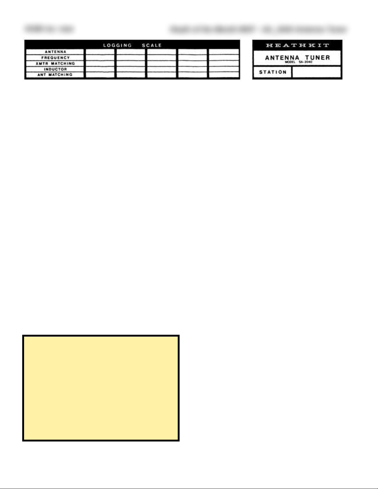
black and white lettering. It includes a window to allow viewing the turns-counter. There
is also an erasable table area where one may
mark down settings for later reference as well
as a place to put the station call-letters using
supplied vinyl lettering. This area is shown in
figure 2. The cabinet is painted black, and the
rear panel is painted a light gray with black
lettering.
The SA-2040 Controls and Connections:
The front panel of the SA-2040 has three
large control knobs. On the left, TRANSMIT-
TER MATCHING adjusts the dual-section in-
put capacitor. The dial is marked 0 - 100 in 5
unit increments over 180°; every other increment is numbered. In the center, INDUC-
TOR controls the roller inductor. It has no
dial markings, but to the left of its knob is
the window of a turns-counting dial. Every
full turn of the inductor is represented by 10
counts on the dial. The inductor has about 25
turns or 250 counts. On the right, ANTENNA
Copyright 2020, R. Eckweiler & OCARC, Inc.
Page of 2 10
Heathkit SA-2040 Specifications
Frequency Range 3.5 – 30 MHz (80, 75, 40, 30,"
20, 17, 15, 12, 10 meter bands)
Power Capability (input) SSB: 2 KW PEP"
CW: 1 KW
Input Impedance: 50 Ω
Impedance Transformation: 4:1 (balance to unbalanced)"
balun
Output Impedance: Wide range
Table I
Figure 2: On the front panel is an erasable place to write settings as well as a place to add your station call letters.
W6ZE
Page 3
HOM rev. new
Heath of the Month #097 - SA_2040 Antenna Tuner
MATCHING adjusts the output capacitor and is marked
in a similar manner as the
TRANSMITTER MATCHING
control.
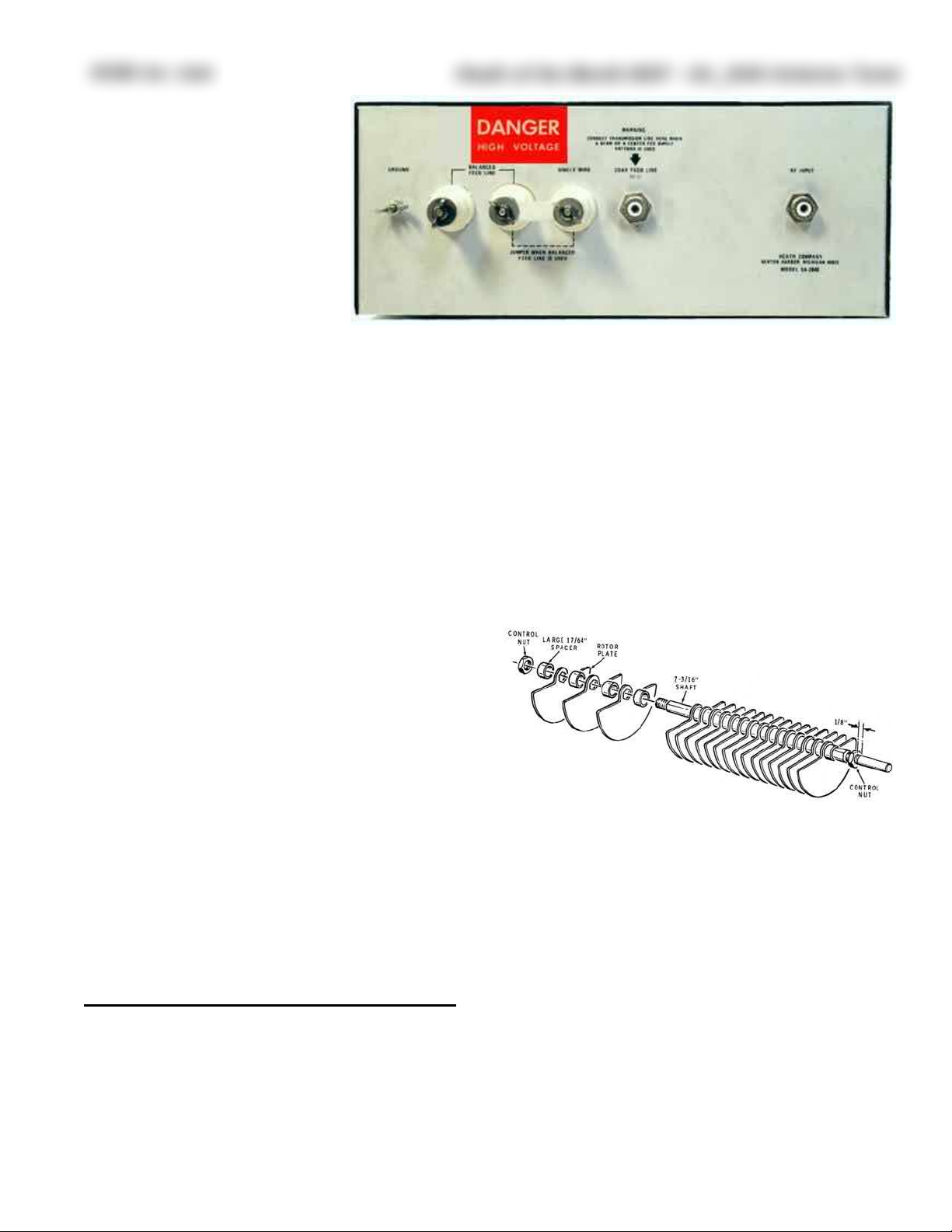
The input and outputs are all
located on the rear panel
(Figure 3). Viewed from the
rear, (left to right) are: a
ground terminal with a wing
nut; two large ceramic feedthrough insulators (J5 and J4) for a parallel
feedline; a large ceramic feedthrough insulator (J3) for a single-wire antenna; a UHF coax
connector (J2) for a coaxial antenna; and fi-
nally another UHF coax connector (J1), for
the input from the transmitter. A large space
is left between J1 and J2 to help prevent them
from being mixed-up. When using a parallel
feedline a connecting strap must be connected
between the middle and right ceramic feedthrough insulators (J4 and J3). This strap may
be stored across J5 and J4 when not using a
parallel feedline. Wing nuts are used on these
insulators to expedite secure connections.
The SA-2040 Construction:
Heathkit refers to the SA-2040 assembly as a
“two evening project”. After the parts are
checked assembly begins. Here is where you
get a surprise. No need to fire up the soldering iron yet, first you have to assemble the
two large variable capacitors and the continuously variable inductor. Then the balun
toroids must be prepared and wound. Finally
you’ll be heating the iron to tin the balun
leads and solder on a pair of screw lugs.
ANTENNA MATCHING Capacitor Assembly:
First the ANTENNA MATCHING capacitor C2
is built. The rotor section, (Figure 4) assem-
bles with a hex shaft, two control nuts, nineteen 17/64” spacers and eighteen rotor plates.
Next, the front capacitor plate is assembled
by adding two ceramic insulators to the metal
front plate using four #8 screws and eight
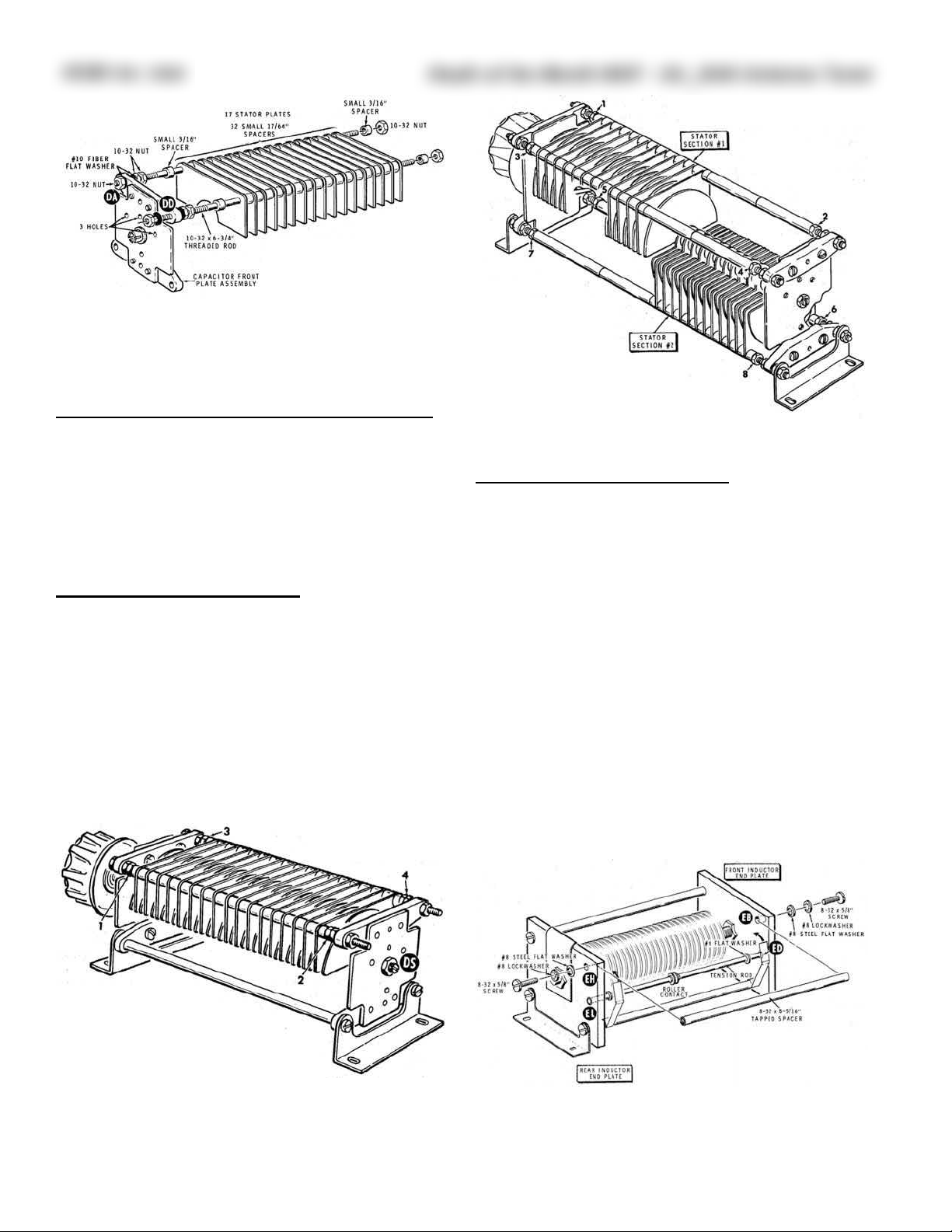
fiber washers. Then the stator assembly (Fig-
ure 5) is built using two 6¾" #10-32 threaded
rods, four large fiber washers, eight nuts, four
3/16” spacers, thirty-two 17/64” spacers, seventeen stator plates and the previously assembled front plate. The rotor and stator sections are then mated adding conical and
forked springs, and lubrication is applied using grease supplied with the kit. Next, the capacitor rear plate is assembled, in a similar
fashion to the front plate, and installed. Finally a knob is temporarily installed on the capacitor shaft and nuts are adjusted so the stator plates are centered between the rotor
plates (Figure 6). Rotational tension is adjusted as necessary, the knob is removed, and C2
is set aside. The assembly of C2 takes up five
pages in the manual and a full page in the
Copyright 2020, R. Eckweiler & OCARC, Inc.
Page of 3 10
Figure 4: C2 Rotor Assembly; from Heathkit Manual.
Figure 3: Heathkit SA-2040 Rear Panel. Outputs are on the left. Input is on the right.
Page 4
HOM rev. new
Heath of the Month #097 - SA_2040 Antenna Tuner
separate large illustration booklet using four
pictorial, four detail and three inset drawings.
TRANSMITTER MATCHING Capacitor Ass’y:
The dual-section TRANSMITTER MATCHING
capacitor C1 (Figure 7) is assembled next. Its
assembly is a bit more complicated since there
are two separate stator sections. The C1 as-
sembly also takes up five manual pages as
well as two pages in the illustration booklet.
Roller INDUCTOR Assembly:
The continuously variable rotary inductor L1
is then assembled. The silver-plated inductor
comes mounted on a ceramic drum with
shafts attached. End plates and the roller contact mechanism are assembled around the rotor inductor. Assembly of L1 takes four pages
in the manual and another page in the illustration book.
Balun Transformer Assembly:
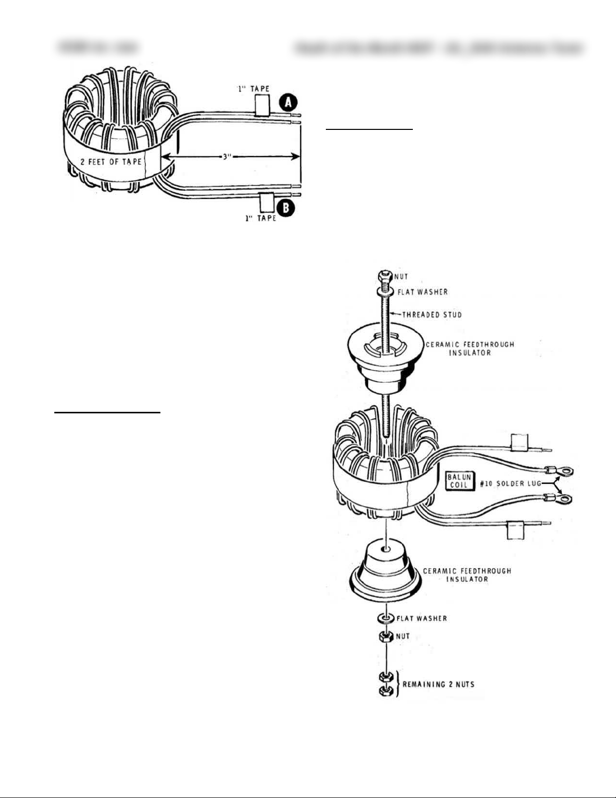
The balun transformer T1 uses two large
toroidal cores. Before winding the coil, each
core is separately insulated with supplied
glass-cloth tape, and then the two cores are
placed atop each other and tape is wound
around both cores along the full circumference. An eleven foot length of heavy stranded
teflon-insulated wire is doubled over at its
center and wound onto the toroid to create
fifteen bifilar turns. A two-foot length of
glass-cloth tape is then wound around the
circumference of the coil to hold the windings
in place. The doubled wire is cut apart, and
the four wire ends are trimmed to length and
tinned. Using an ohmmeter, the winding
Copyright 2020, R. Eckweiler & OCARC, Inc.
Page of 4 10
Figure 5: C2 Stator Assembly; from Heathkit Manual.
Figure 6: Completed C2 showing plate spacing adjustments;
from Heathkit Manual.
Figure 7: Completed C1; from Heathkit Manual.
Figure 8: L1 during assembly; from Heathkit Manual.
Page 5
HOM rev. new
Heath of the Month #097 - SA_2040 Antenna Tuner
leads are identified and marked with tape
(Figure 9). The tape is placed on one winding
at the starting end and on the other winding
at the finished end. #10 lugs are then soldered on the two untaped leads. A ceramic
feedthrough is used unconventionally to make
a mounting post for the balun (Figure 10). As-
sembling the balun transformer T1 takes five
pages in the manual.
Chassis Assembly:
Once the two capacitors, roller inductor and
balun are assembled, chassis assembly is
started. The turns counter is assembled and
mounted, the front panel “vinylite” face is
mounted to the front panel, shaft bushings
are installed for the three front panel controls, and the shaft with nylon gear is installed on the turns-counter shaft. On the
rear panel the two UHF connectors, three
large feedthrough insulators and grounding
bolt with wing nut are mounted. The balun T1
is mounted next. The two taped leads are soldered to a ground lug on the inside of the
chassis at the grounding bolt, and the two
remaining leads are attached to feedthroughs.
The roller inductor, and two variable capacitors are aligned with and mounted to the
chassis and attached to insulated shafts that
fit through the bushings on the front panel. A
beveled nylon gear is first mounted on the in-
ductor shaft that meshes with the gear on the
turns-counter shaft. The turns-counter is calibrated and the gears are tightened.
Chassis Wiring:
Wiring the components together is done by
straps and short lengths of #10 bare wire.
Two silver-plated straps are used. One connects L1 to C1 and C2; the second connects
C2 to the J3 feedthrough. A short piece of
#10 wire connects J1 to a lug that bolts to
Copyright 2020, R. Eckweiler & OCARC, Inc.
Page of 5 10
Figure 9: Assembled T1 balun; from Heathkit Manual.
Figure 10: T1 balun mounting, see text; from Heathkit Manual.
Page 6
HOM rev. new
Heath of the Month #097 - SA_2040 Antenna Tuner
C1; another short piece of #10 wire connects
J2 to a lug that bolts to J3.
This completes the soldering. In all four
leads were tinned, four solder lugs were soldered to the ends of those wires and three
other soldering connections were made.
Final Assembly:
After the “Blue Label” that contains the kit’s
model and series numbers is attached to the
inside rear of the chassis, the feet are installed. Heathkit offers a choice of the kit sitting flat or tilted at an angle by adding extensions to the two front feet. Knobs are attached, and after a thorough inspection the
cabinet is attached using eight black machine screws.
SA-2040 Circuit:
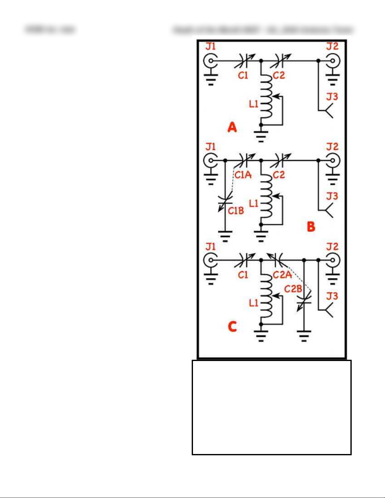
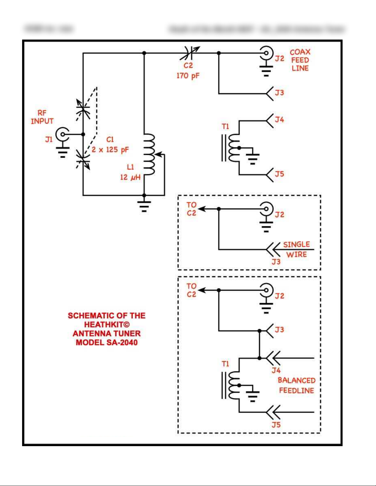
The SA-2040 circuit diagram is shown in
Figure 14 at the end of the article. It is one of
two popular design derivatives of the Teematching network (Tee-Transmatch5). The
basic Tee-Transmatch network is shown in
Figure 10A. It does a good job of matching
even very high SWR loads (The W8ZR antenna tuner6 can match up to an SWR of
16:1). What it lacks is good harmonic attenuation, especially if improperly tuned. Figure
10B is a modification of the Tee-Transmatch
called the Ultimate Transmatch previously
mentioned. It adds another section to the input variable capacitor to ground and was
said to have better harmonic suppression.
Later it was found that the extra capacitor
added little if any performance advantage.
An “improved circuit”, called the SPC network, “because the word ‘ultimate’ had al-
ready been used”, is shown in Figure 10C.
SPC stands for “series, parallel capacitance”.
The SPC did do a better job of harmonic suppression and was described in the ARRL
Handbook for many years. It did have two
drawbacks, the first being the tuning was
Copyright 2020, R. Eckweiler & OCARC, Inc.
Page of 6 10
Figure 10: Three Popular Transmatch Schematics:
A: Tee Matching Network (Tee-Transmatch Network)
B: Ultimate Transmatch Network
C: Series Parallel Capacitance (SPC) Transmatch Network
In each schematic:
C1 (C1A/B) Transmitter Matching Capacitor(s)
C2 (C2A/B) Antenna Matching Capacitor(s)
L1 Inductor (Rotary or Multi-Tapped)
J1 Coax Input from Transmitter
J2 Coax Output to Low Impedance Antenna
J3 Feedthrough to Single Wire Antenna
Page 7
HOM rev. new
Heath of the Month #097 - SA_2040 Antenna Tuner
very sharp, especially on the lower bands,
and a vernier knob on the capacitors was
needed to ease tuning. The second drawback
turned out to be the one that killed the SPC
design. It was found to be significantly more
lossy than the other two. Heathkit never
used the SPC circuit; the SA-2040 uses the
Ultimate Transmatch circuit and the later
SA-2060(A) and SA-2500 both use the TeeTransmatch circuit. Not shown in the Fig-
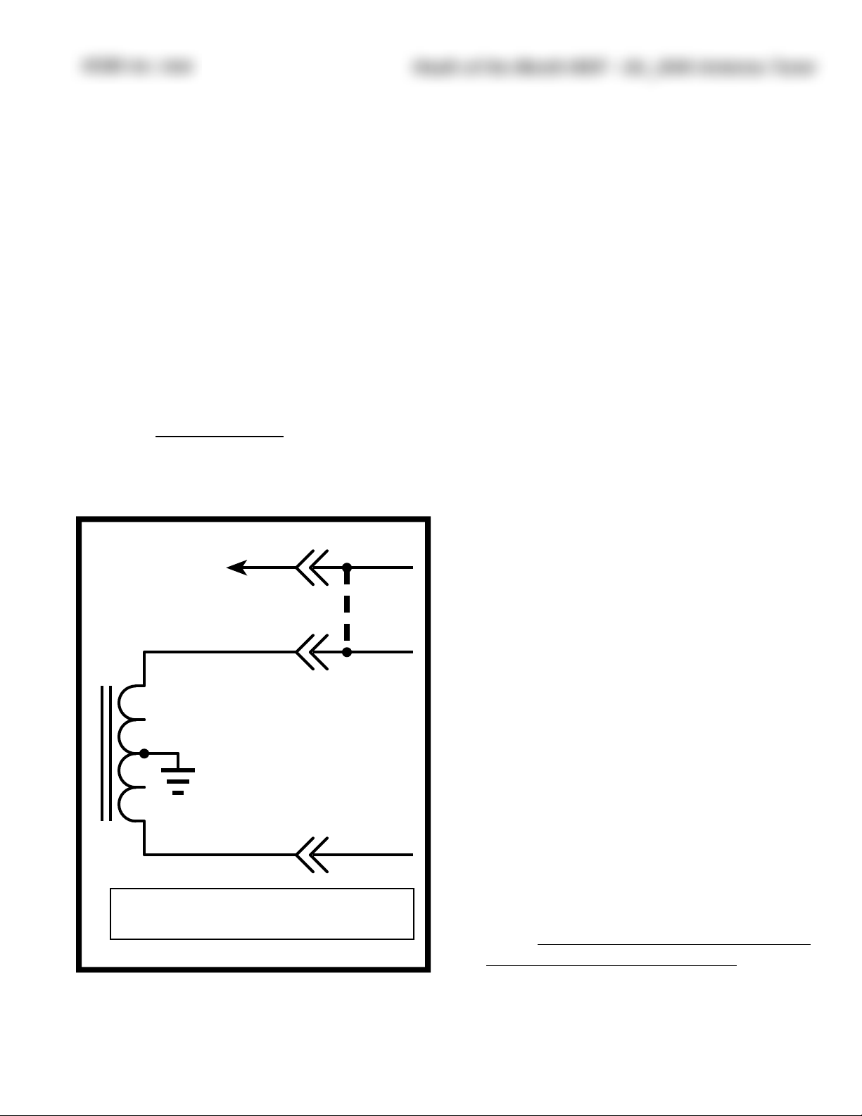
ures 10 is the balun often found in these
tuners. It is shown in Figure 11.
Using the SA-2040:
Setting the three controls on the tuner properly is important. It is possible to get a low
SWR at more than one setting, but the
wrong setting will reduce harmonic suppression, be less efficient and can cause arcing
across the tuning capacitors due to excessive-
ly high voltage. To properly tune-up using
the SA-2040, and most other antenna tuners,
an SWR bridge, placed between the transmitter and antenna tuner is needed. Fancier
tuners, such as the SA-2060(A), have this
capability built in. When using an external
SWR bridge it should be dedicated to the
tuner if the setup will be used on a day to
day basis. Short lengths of 50Ω coax should
be used to connect between the transmitter,
SWR bridge and SA-2040.
In Lew McCoy’s article7, that introduced the
circuit used in the SA-2040(A), he gave basic
adjustment instructions, here is the author’s
interpretation:
1. Start with C1 and C2 at maximum capacitance (fully CCW), and L1 at maxi-
mum inductance for 80/75 meters, about
half inductance for 40/30 meters, about
quarter inductance for 20/17 and about
eighth inductance for 15/12/10 meters.
2. Apply just enough power to get a fullscale reading in the forward direction on
the SWR bridge.
3. Set the bridge to read reflective power,
and slowly adjust L1. At some point the
reflected power will dip sharply; adjust
for a minimum.
4. Now adjust C1 and C2, and touch-up L1
for a perfect match.
5. Now you may increase power to the level
desired. You may want to touch-up the
settings at the higher power.
6. If you change frequency check the match,
and touch-up C1, C2 and L1 to correct
the match if needed.
7. More than one match often is encountered. Always select the match that uses
the highest capacitance settings.
Copyright 2020, R. Eckweiler & OCARC, Inc.
Page of 7 10
From junction of!
C2/C2A and J2
T1
J3
J4
J5
Balanced Feedline
Single !
Wire
Note: Install jumper between J3 and
J4 only when using balanced feedline.
See!
Note
Figure 11: A toroidal balun (T1) may be added to any of the
Transmatch networks discussed for a balanced feedline.
Page 8
HOM rev. new
Heath of the Month #097 - SA_2040 Antenna Tuner
To aid initial operation, Heathkit prov i d e d a t a b l e o f
starting points for
the initial settings
for 80 through 10
meters (non-WARC
bands only). For
each band, settings
are given for the low
and high end of the
band and a third
around mid-band.
This table may be
found in the manual.
Make note of your
settings for each antenna you use so you
can make adjustments quickly when
making large frequency excursions or
changing bands. Note
that things like moisture and obstacles
can cause you to have to adjust your settings
somewhat. Sudden major changes warrant a
physical check of the antenna before transmitting at high power.
Comments:
Today many solid-state radios come with
some sort of antenna tuner built-in or available as an accessory that mounts internally.
These tuners generally provide only a coaxial
output. They help match the transmitter to
an antenna that is resonant at one frequency
in the band by making the antenna capable
of being resonant across the whole band, or
in the case of 80/75 meters across a larger
part of the band.
If you are using a non-resonant antenna
such as a long-wire or end fed antenna, or an
antenna fed by parallel feed (such as twinlead) then a full-fledged antenna tuner such
as the SA-2040 is recommended.
From the Author:
Suggestions are always appreciated for kits
of interest to research and write about. April
will soon be upon us and, as some know, I
often try to pick an unusual kit to write
about in celebration of April Fool’s Day. Suggestions for April are also welcome, though I
believe I have found an unusual one for
2020. Due to the holidays I probably won’t
have an article for January, which could
make the April article #100.
In HotM #95 I wrote about the A-1 Audio
Amplifier, the first hi-fi kit offered by Heathkit. I’m still looking for any documentation
Copyright 2020, R. Eckweiler & OCARC, Inc.
Page of 8 10
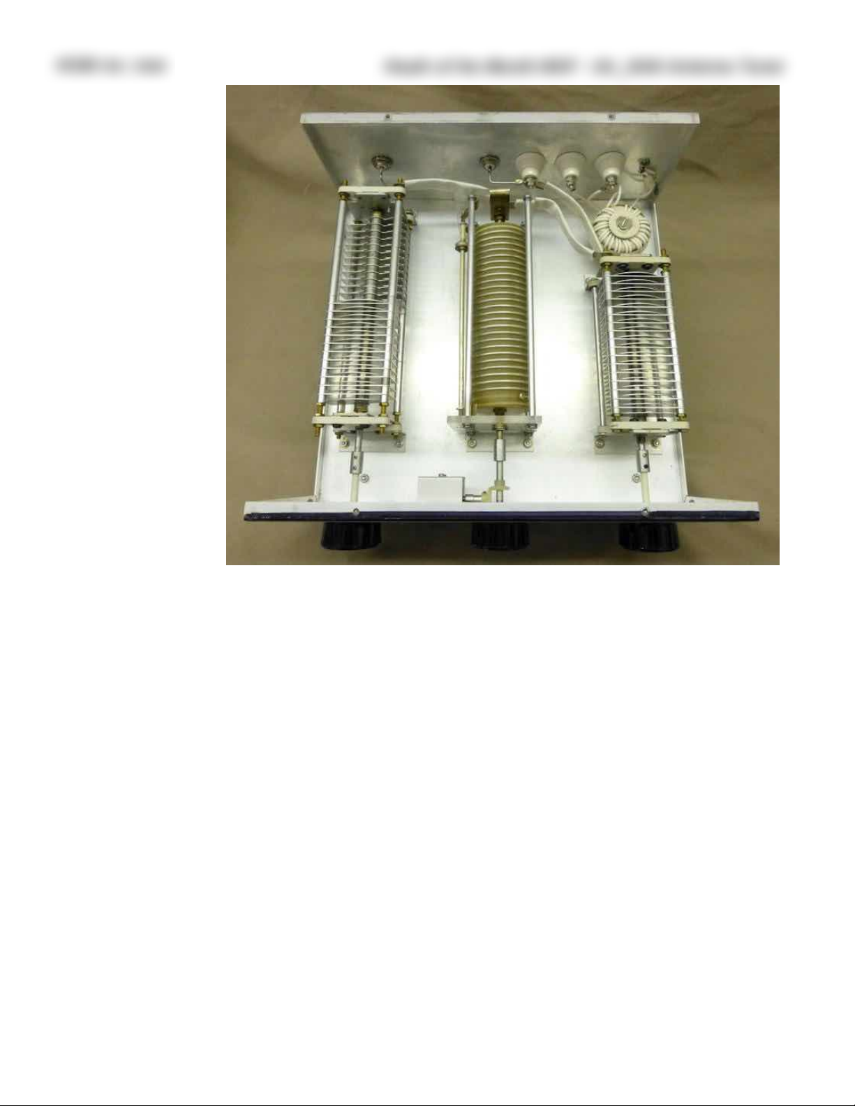
Figure 12: Interior view of the SA-2040. C1 is on the left, and C2 is on the right. Behind C2 is the
balun T1. The Inductor L1 is in the center. Photo by Bob Koller - KG7EMO; used with permission.
Page 9
HOM rev. new
Heath of the Month #097 - SA_2040 Antenna Tuner
anyone has on that kit. I have not found the
original schematic, though one dated August
18, 1948 is on the web. Unfortunately this
turns out to be a schematic later released by
Heathkit so users could upgrade their A-1 to
the A-2. That schematic uses a 6SL7 preamplifier tube while the original uses a 6SN7. If
you have an A-1 or the documentation,
please contact me. You may email me by
clicking on the link at the bottom of the
copyright box.
73, from AF6C
NOTE: This article was originally written to
appear in the December 2019 issue of RF but
was held until January of 2020 due to circumstances beyond the control of the author.
Copyright 2020, R. Eckweiler & OCARC, Inc.
Page of 9 10
This article is Copyright 2020 R. Eckweiler,
AF6C and The OCARC Inc.
Remember, if you are getting rid of any old
Heathkit Manuals or Catalogs, please pass
them along to me for my research.
Thanks - AF6C
Notes:
1. Discussed in Heathkit of the Month #13.
2. Lewis McCoy W1ICP, The Ultimate Transmatch, QST
July 1970, p. 24.
3. Paul Pagel, N1FB, Heath SA-2040 Antenna Tuner
Product Review, QST November 1980 pp. 49, 50.
4. ibid.
5. Lewis McCoy W1ICP, The 50-Ohmer Transmatch, QST
July 1961 p. 30. ‘[Transmatch is a] generic name
coined by the editors [of QST] to apply to any type of
matching network inserted between a transmitter and a
transmission line. There has been an obvious need for
such a term, since “antenna coupler” is inadequate
both technically and psychologically.’
6. James Garland, W8ZR, The EZ-Tuner [Part 1], QST
April 2002, pp 40 - 43.
7. McCoy W1ICP 1970.
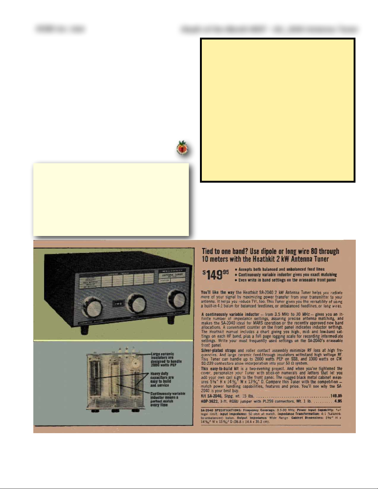
Figure 13: Ad for the SA-2040 Antenna Tuner from the Fall 1980 Heathkit Catalog (#850)
Page 10
HOM rev. new
Heath of the Month #097 - SA_2040 Antenna Tuner
Copyright 2020, R. Eckweiler & OCARC, Inc.
Page of 10 10
Figure 14
 Loading...