

Page 1
© 2007 HeathCo LLC 598-1165-05
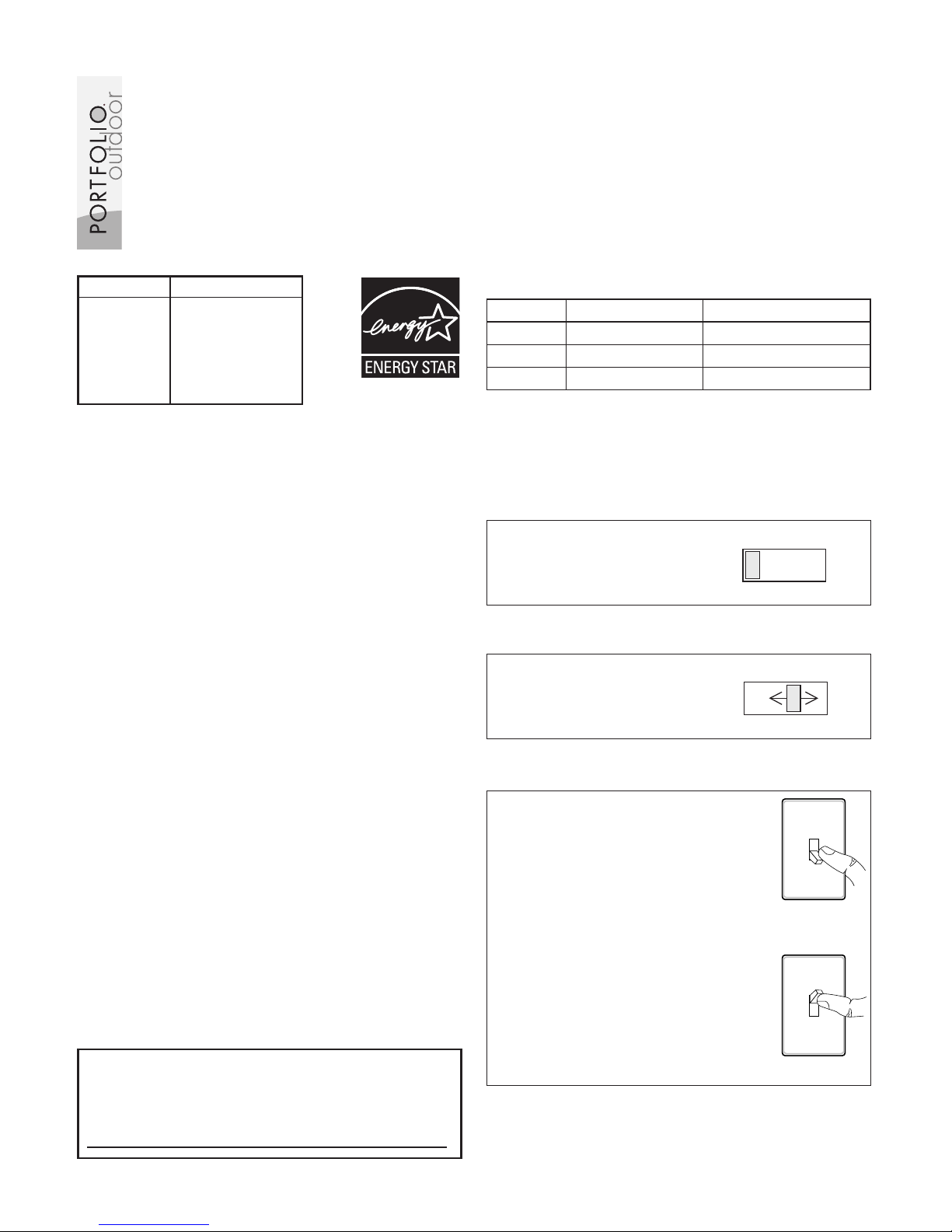
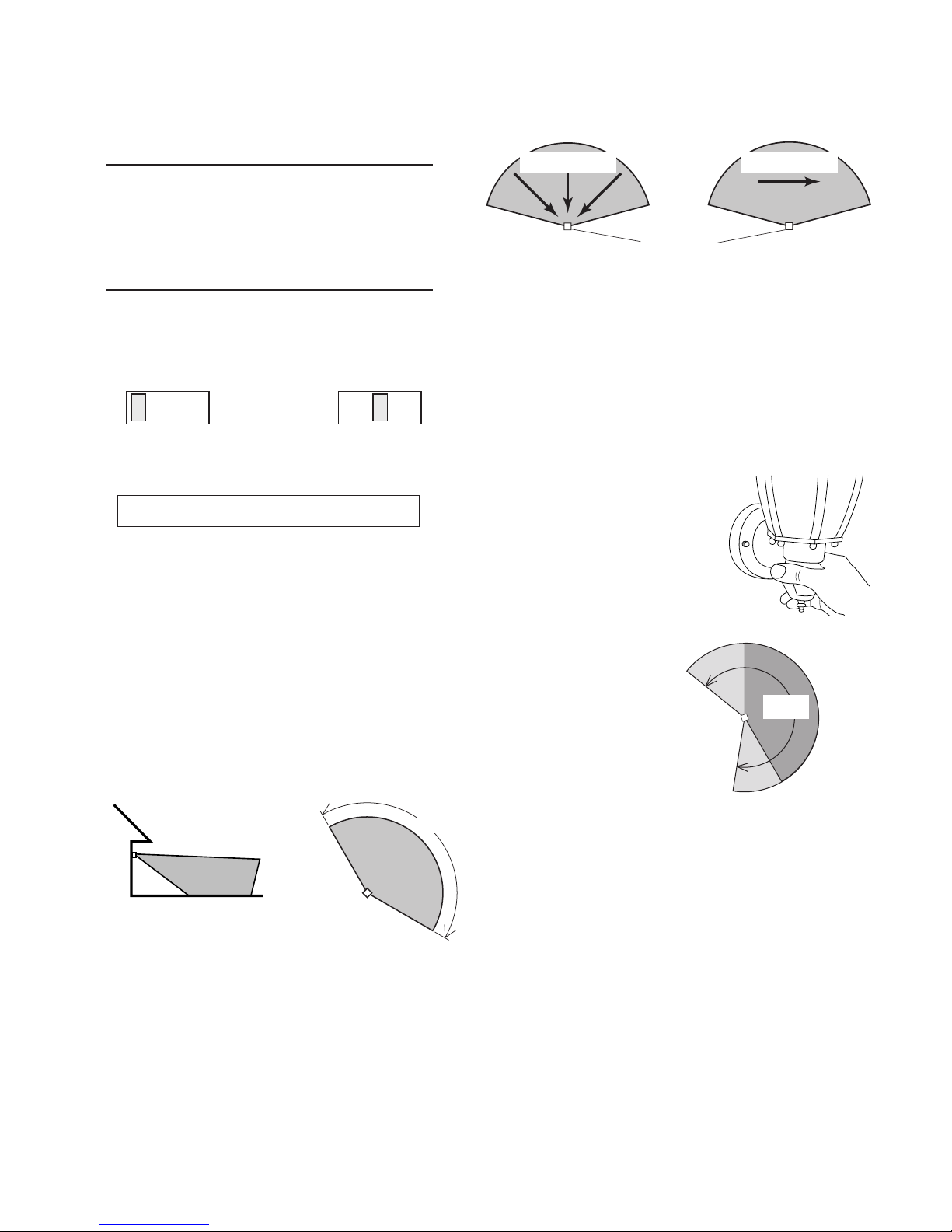
ON-TIME
TEST 1 5 10 MIN
Set ON-TIME switch to 1,
5, or 10 minutes.
ON-TIME
Set the ON-TIME switch
on the bottom of the cover
plate to TEST.
... back on.
1 Second
OFF then...
Manual mode only works at
night because daylight returns
the sensor to AUTO.
Flip the light switch off for one
second then back on to toggle
between AUTO and MANUAL
MODE.
Manual mode works only with
the ON-TIME switch in the 1,
5, or 10 position.
Note: When first turned on wait about 1 1/2
minutes for the circuitry to calibrate.
MANUAL MODE
AUTO
TEST 1 5 10 MIN
* resets to Auto Mode at dawn.
OPERATION
TEST
Motion Sensing
Coach Lights
Before installation, record the model number
from back of fixture below. Attach receipt in
case of possible warranty issues.
Mode: On-Time Works: Day Night
Test
5 Seconds x x
Auto
1, 5, or 10 Min x
Manual
To Dawn* x
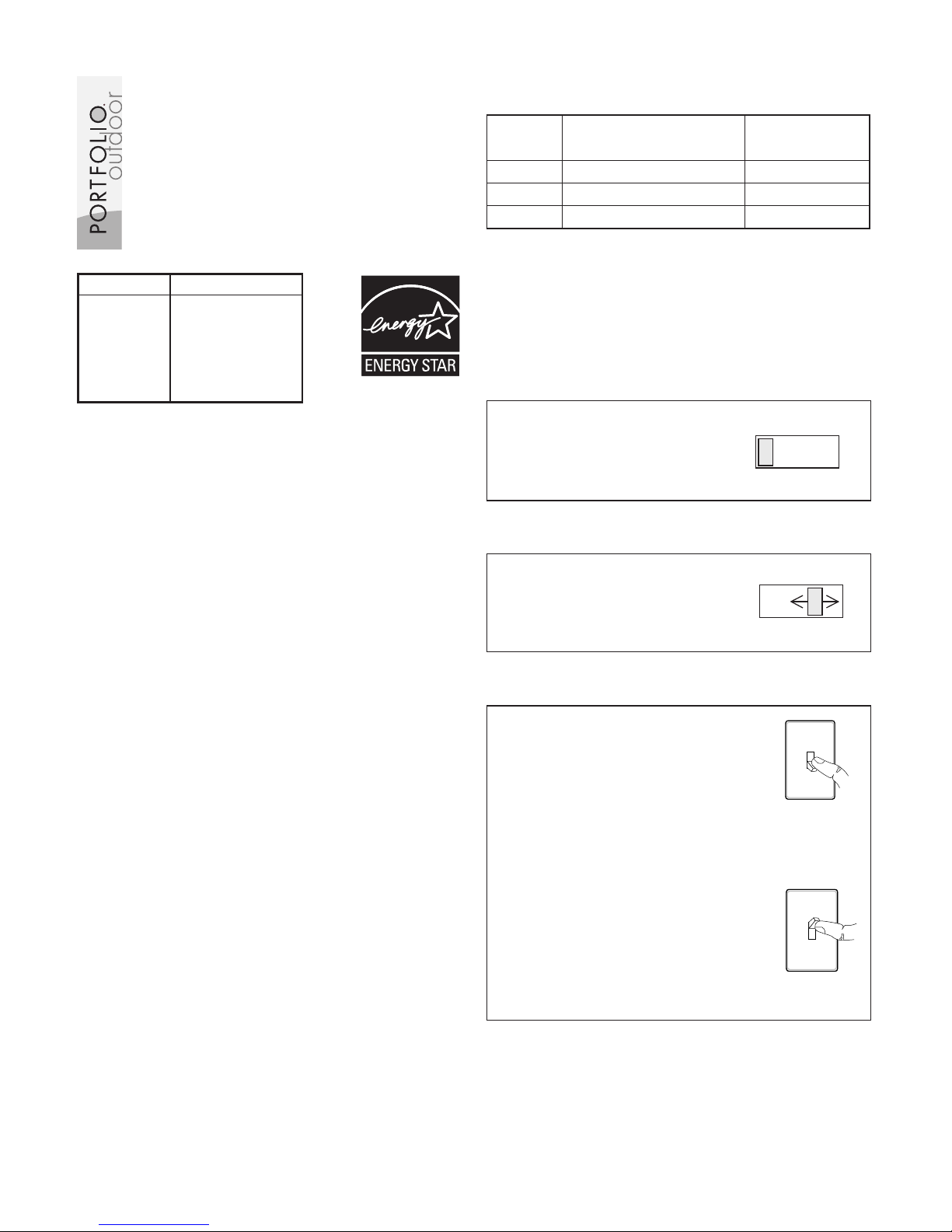
Items Models
008812 PF-4150-SC
066300 PF-4150-PB
066494 PF-4150-BK
066565 PF-4160-AB
066579 PF-4162-PB
066580 PF-4170-PB
Questions or problems? Before returning
to your retailer, refer to the troubleshooting
guide in this manual or call our technical service department at 1-800-858-8501 (English
speaking only), 7:30 am to 4:30 pm, CST,
Monday – Friday.
Features
• Light comes on when motion is detected.
• Automatically turns light off.
• Photocell keeps the light off during daylight
hours.
Package Contents
• Lantern
• Easy to use Universal Mounting Bracket
• Mounting Hardware
• Wire Connectors
• Some Models Include an Optional Decora
-
tive Tail Assembly
Requirements
• The light control requires 120 volts AC.
• If you want to use Manual Mode, the control
must be wired through a switch.
• Some electrical codes require installa
-
tion by a qualified electrician.
Page 2
2
598-1165-05
INSTALLATION
Estimated Installation Time: 30 minutes
Items needed for installation (not included):
• Phillips and flathead screwdrivers
• Pliers • Wire strippers/cutters
• Safety glasses • Light bulb
• Silicone caulk
For best performance, mount the fixture about
6 feet (1.8 m) above the ground.
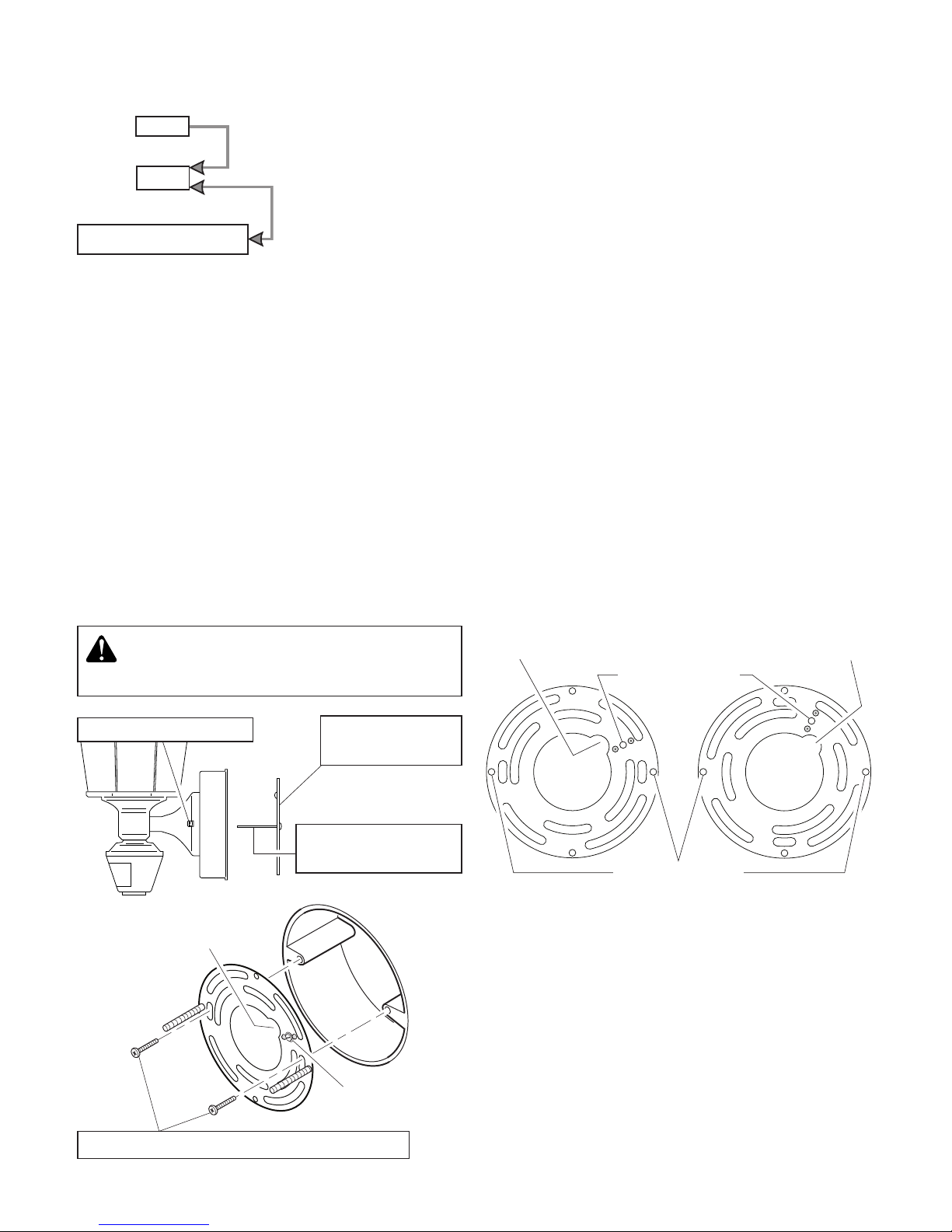
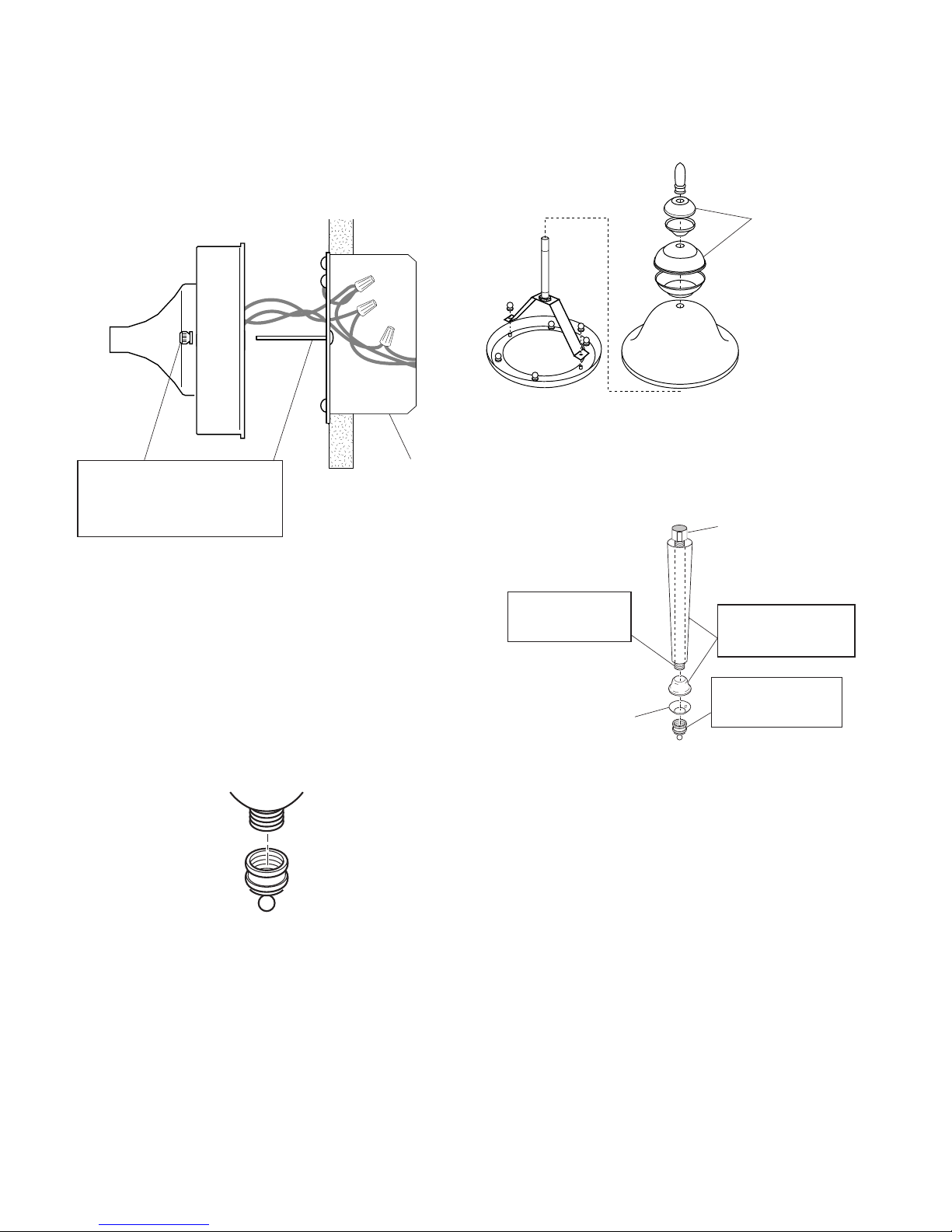
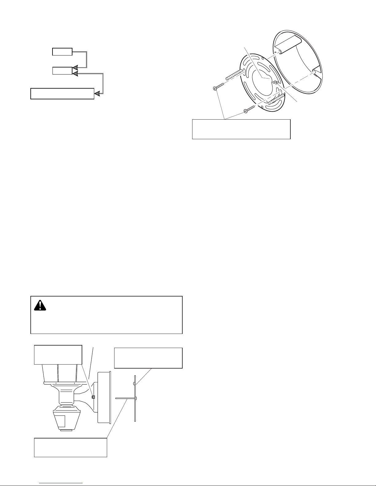
1. Remove two nuts.
3. Tighten screws
finger tight.
2. Remove
Mounting Plate.
WARNING: Turn power off at circuit
breaker or fuse.
ON-TIME Switch at 1, 5,
or 10 minutes
Mode Switching Summary
Flip light switch
off for one second
then back on*
* If you get confused while switching modes,
turn the power off for one minute, then back
on. After the calibration time the control will
be in the AUTO mode.
MANUAL MODE
AUTO
TEST
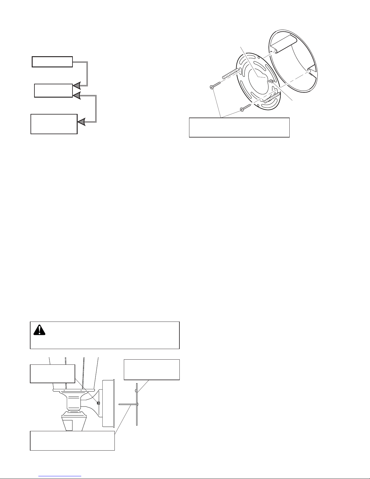
This fixture comes with a universal mounting
bracket. It is pre-assembled on the fixture to
fit the majority of junction box applications.
However, if the slots on the mounting plate
do not line up with the junction box screw
holes:
1. Remove the fixture mounting screws from
the mounting plate. Note: Do not remove
the ground screw.
2. Attach ground wire “pigtail” to ground
screw on mount ing plate (See
Recommended Grounding Method for
additional information).
3. Flip the mounting plate over.
4. Rotate the mounting plate so the wire path
is on the upper right. Note: The wire path
on the mounting plate must be located
as shown below to allow the wires on the
back of the fixture to pass through.
5. Reinstall the fixture mounting screws and
attach the mounting plate to the junction
box as shown.
Wire Path
4. Attach mounting plate to junction box.
Wire Path
Ground Screw
As Shipped Flipped and
Rotated
Wire Path
Fixture Screws
Ground Screw
Page 3
3
598-1165-05
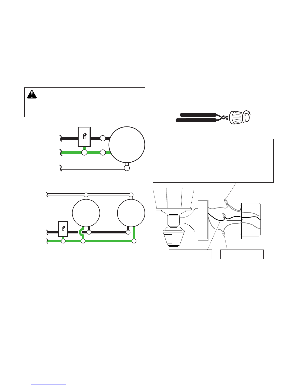
Black to black
White to white
Recommended Grounding Method
Use a green ground “pigtail” (not provided) and
twist one end together with the bare fixture wire
and the box ground wire. Secure with a wire
connector. Secure the other end of the “pigtail”
with the GND screw on the mounting plate.
WIRING
One Motion Light
❒ Twist the junction box wires and the
fixture wires together as shown below.
Secure with wire connectors. If you have
a metal junction box, you may not need
the green “pigtail”. If you are unsure about
the grounding method, consult your local
building code.
Two Motion Lights
Black
White
Green
or Bare
Light
Fixture
Black
White
Green
or Bare
Light
Fixture
Light
Fixture
CAUTION: DO NOT connect the RED
wire unless you want to control other
lights from the motion sensor.
Note: All wiring should be run in accordance
with the National Electrical Code through
conduit or another acceptable means.
Contact a qualified electrician if there is
any question as to the suitability of the
system.
Connect the fixture wires to the wires in the
junction box. Twist the wires together and
secure with wire connectors.
Page 4
4
598-1165-05
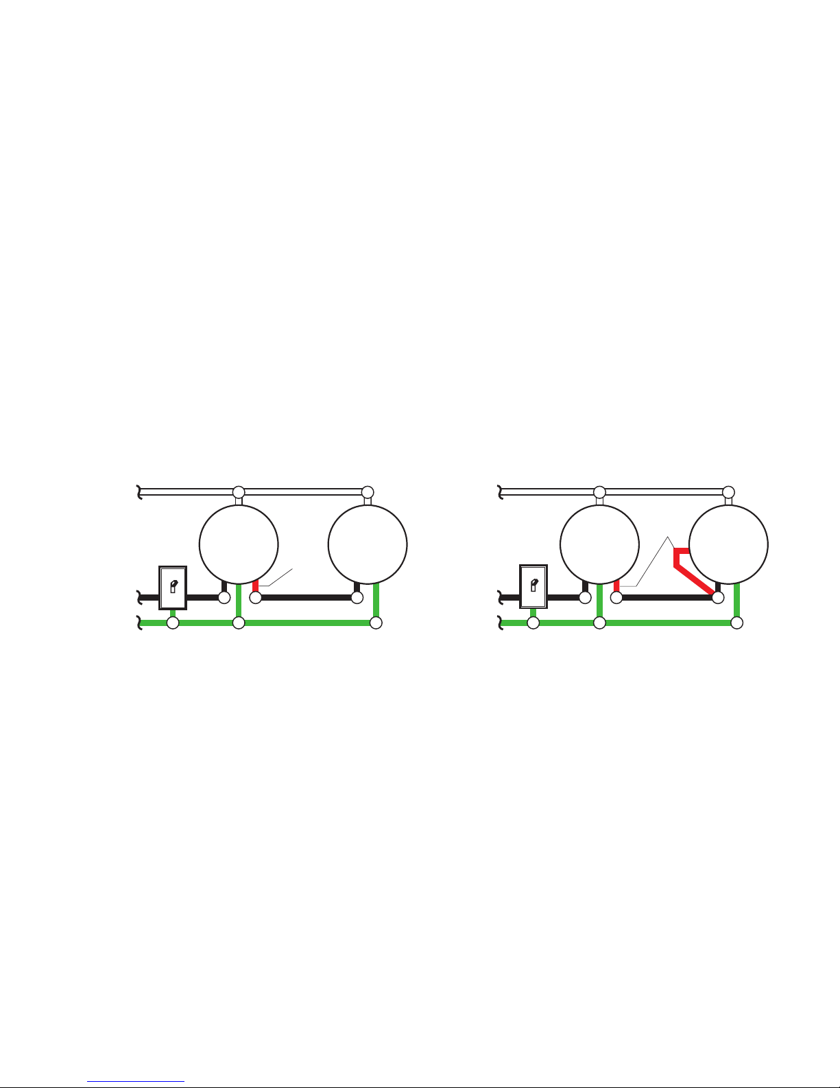
OPTIONAL WIRING
This fixture is provided with a sensor rated for 500 Watts. Since the fixture is only rated 100
Watts, 400 Watts of additional lighting may be controlled by this sensor.
When determining what a fixture is rated for, do not simply look at the rating on the lamp in
the fixture. Look at the marking which specifies the maximum lamp wattage for which the
fixture is suitable.
Once you have selected the fixtures to be connected and determined their maximum ratings,
add these ratings up. For instance, if you have 3 fixtures rated 100 Watts, 150 Watts, and
75 Watts respectively, you have a total load of 325 Watts.
Wiring Diagram 1 – When wiring to control a standard light fixture: Strip the motion sensor’s
red wire and connect to the standard light’s black wire. Connect all white wires together.
Total fixture ratings must not exceed 500 Watts (4.1 A).
Wiring Diagram 2 – When wiring to control another motion sensing light fixture (Master /
Slave): Strip the red wire in both light fixtures. Connect the red wire of the controlling (master)
fixture to the red and black wires of the controlled (slave) fixture. Connect all white wires
together. Total fixture ratings must not exceed 500 Watts (4.1 A).
Wiring Diagram 1
Black
White
Green
or Bare
Light
Fixture
Light
Fixture
Wiring Diagram 2
(Standard)
Master Slave
It is also possible to wire two motion lights so that either fixture will turn on both lights at the
same time (dual master system). It is recommended that only people with plenty of electrical
experience attempt this configuration. Please call our customer service number (1-800-8588501 - English speaking only) before attempting this wiring. If the dual master wiring is not
done correctly, it can destroy both motion sensing fixtures and void your warranty.
Black
White
Green
or Bare
Light
Fixture
Light
Fixture
Red
Red
Page 5
5
598-1165-05
❒ Caulk fixture mounting surface with
silicone weather sealant.
❒ Install one 100 Watt maximum light bulb.
❒ If so equipped, install the fixture top. Secure
with decorative screws.
❒ If you will not be installing the optional tail
assembly, install the decorative nut onto
the bottom of the fixture now.
Slide the fixture onto the
mounting screws and
tighten nuts.
Junction
Box
Optional Assembly
❒ If so equipped, you may install the decora-
tive tail as shown below.
1. Screw in
extension bar.
2. Add tail piece
and trim.
3. Install
decorative nut.
Bottom trim piece
has drain hole
Hex nut
4162 Top Assembly
Larger piece
on top
COMPLETE THE INSTALLATION
❒ Stuff the wires into the junction box. Make
sure the wires from the fixture go through
the wire path, and no wires get pinched.
Page 6
6
598-1165-05
TESTING
❒ Turn on the circuit breaker and light
switch.
❒ Set the SENSITIVITY as needed. Too much
sensitivity may increase false triggering.
❒ Set the amount of TIME you want the light
to stay on after motion is detected. (1, 5,
or 10 minutes).
240°
Sensor Aiming
Adjustment Angle
❒ Walk through the coverage area noting
where you are when the lights turn on.
Move the sensor head left or right to
change the coverage area.
Note: Grasp the sensor
only as shown and turn
the entire sensor. Any
other method may
damage the sensor.
Do not force it past
the stops.
Least Sensitive Most Sensitive
30 ft.
(9.1m)
Maximum Range Maximum
Coverage Angle
The detector is less sensitive to motion directly towards it and more sensitive to across
motion.
Sensor
MotionMotion
6 ft.
(1.8 m)
Avoid aiming the control at:
• Pools of water or objects that change
temperature rapidly, such as heating vents
and air conditioners. These heat sources
could cause false triggering.
• Areas where pets or traffic may trigger
the control.
• Nearby large, light-colored objects
reflecting daylight may trigger the shut-off
feature. Do not point other lights at the
sensor.
Note: Sensor has a 1 1/2 minute warm up pe-
riod before it will detect motion. When
first turned on wait 1 1/2 minutes.
TEST 1 5 10 MIN
ON-TIME
LO - M - HI
SENSITIVITY
150°
❒ Set SENSITIVITY to mid position and
ON-TIME to TEST position.
Page 7
7
598-1165-05
SPECIFICATIONS
Range . . . . . . . . . . Up to 30 ft. (9.1 m)
[varies with surrounding
temperature].
Sensing Angle . . . . Up to 150°
Electrical Load . . . . U p t o 1 0 0 Wat t
Maximum Tungsten
Incandescent
Sensor Capacity . . Up to 500 Watt (4.1
A.) Maximum Tungsten
Incandescent
Power Requirements .... 120 VAC, 60 Hz
Operating Modes . . TEST, AUTO, a n d
MANUAL MODE
Time Delay . . . . . . 1, 5, 10 minutes
HeathCo LLC reserves the right to discontinue products and to change specifications
at any time without incurring any obligation
to incorporate new features in products previously sold.
TROUBLESHOOTING GUIDE
SYMPTOM
Light stays on
continuously.
Light flashes
on and off.
POSSIBLE CAUSE
1. The sensor is pointed toward
a heat source like an air vent,
dryer vent, or brightly-painted
heat-reflective surface. (Re-aim
sensor.)
2. Light control is in Manual Mode.
(Switch to Auto.)
3. Sensitivity is set too high.
(Reduce sensitivity.)
1. Heat being reflected from other
objects may be affecting the
sensor. (Re-aim sensor.)
2. Light control is in the Test
mode and w ar ming u p
(flashing is normal under these
conditions).
POSSIBLE CAUSE
1. Light switch is turned off.
2. Bulb is loose or burned out.
3. Fuse is blown or circuit breaker
is turned off.
4. Daylight turn-off is in effect
(recheck after dark).
5. Incorrect circuit wiring, if this
is a new installation.
6. Re-aim the sensor to cover
desired area.
1. Light control may be installed
in a relatively dark location.
2. Light control is in Test. (Set
control switch to an ON-TIME
position.)
1. Light control may be sensing
small animals or automobile
traffic (re-aim sensor).
2. Sensitivity is set too high.
(Reduce sensitivity.)
SYMPTOM
Light will not
come on.
Light comes on
in daylight.
Light comes on
for no apparent
reason.
Page 8

8
598-1165-05
THREE YEAR LIMITED WARRANTY
This is a “Limited Warranty” which gives you specific legal rights. You may also have other rights
which vary from state to state or province to province.
For a period of three years from the date of purchase, any malfunction caused by factory defective
parts or workmanship will be corrected at no charge to you.
Not Covered - Repair service, adjustment and calibration due to misuse, abuse or negligence,
light bulbs, batteries, and other expendable items are not covered by this warranty. Unauthorized
service or modification of the product or of any furnished component will void this warranty in its
entirety. This warranty does not include reimbursement for inconvenience, installation, setup time,
loss of use, unauthorized service, or return shipping charges.
This warranty covers only HeathCo LLC assembled products and is not extended to other equipment and components that a customer uses in conjunction with our products.
THIS WARRANTY IS EXPRESSLY IN LIEU OF ALL OTHER WARRANTIES, EXPRESS OR
IMPLIED, INCLUDING ANY WARRANTY, REPRESENTATION OR CONDITION OF MERCHANT
ABILITY OR THAT THE PRODUCTS ARE FIT FOR ANY PARTICULAR PURPOSE OR USE,
AND SPECIFICALLY IN LIEU OF ALL SPECIAL, INDIRECT, INCIDENTAL, OR CONSEQUENTIAL DAMAGES.
REPAIR OR REPLACEMENT SHALL BE THE SOLE REMEDY OF THE CUSTOMER AND
THERE SHALL BE NO LIABILITY ON THE PART OF HEATHCO LLC FOR ANY SPECIAL, INDIRECT, INCIDENTAL, OR CONSEQUENTIAL DAMAGES, INCLUDING BUT NOT LIMITED TO
ANY LOSS OF BUSINESS OR PROFITS, WHETHER OR NOT FORESEEABLE. Some states
or provinces do not allow the exclusion or limitation of incidental or consequential damages, so
the above limitation or exclusion may not apply to you. Please keep your dated sales receipt, it
is required for all warranty requests.
TECHNICAL SERVICE
Please call 1-800-858-8501 (English speaking only) for assistance before returning
product to store.
If you experience a problem, follow this guide. You may also want to visit our Web site at:
www.hzsupport.com. If the problem persists, call* for assistance at 1-800-858-8501 (English
speaking only), 7:30 AM to 4:30 PM CST (M-F). You may also write* to:
HeathCo LLC
P.O. Box 90004, Bowling Green, KY 42102-9004
ATTN: Technical Service
* If contacting Technical Service, please have the following information available: Model
Number, Date of Purchase, and Place of Purchase.
No Service Parts Available for this Product
Page 9

9
598-1165-05
FUNCIONAMIENTO
¿Preguntas o problemas? Antes de
devolver el producto al minorista, lea la guía
de análisis de averías en este manual o llame
a nuestro departamento de servicio técnico
al 1-800-858-8501 (sólo se habla inglés), de
7:30 am a 4:30 pm, Hora Estándar del Centro,
de Lunes a Viernes.
Características
• La luz se prende cuando se detecta movimiento.
• Apaga la luz automáticamente.
• La fotocélula mantiene la luz apagada
durante las horas del día.
Contenidos del Paquete
• Farol
• Soporte universal de fácil uso
• Ferretería de montaje
• Conectores de alambre
• Algunos modelos incluyen un conjunto
opcional para extensión decorativa.
Requisitos
• El control de luz requiere 120 VCA.
• Para usar el Sobrecontrol Manual, conecte
el control con un interruptor.
• Algunos códigos requieren instalación
por un electricista calificado.
*Se pone en Automático al amanecer.
1 segundo
APAGADO
luego...
El modo manual funciona
sólo por la noche porque la
luz del día pone al detector
en modo AUTOMATICO.
Apague el interruptor por
un segundo y vuélvalo a
prender.
El modo manual funciona
sólo cuando el interruptor
de tiempo (ON-TIME) está
en la posición de 1, 5 ó 10
minutos.
ON-TIME
TEST 1 5 10
ON-TIME
Ponga el interruptor de
tiempo (ON-TIME), al fondo
del detector, en la posición
de prueba (TEST).
Ponga el interruptor de tiempo (ON-TIME) en la posición
de 1, 5 ó 10 minutos.
MODO MANUAL
...préndalo.
Nota: Cuando lo prenda por primera vez es-
pere 1 1/2 minutos para que el circuito
se claibre.
© 2007 HeathCo LLC 598-1165-05 S
TEST 1 5 10
AUTOMATICO
PRUEBA
Modalidad: A tiempo: Trabaja: Día Noche
Prueba
5 seg. x x
Autom.
1, 5 ó 10 min. x
Manual
Hasta el
amanecer*
x
Lámparas tipo
cochero con
detector de
movimiento
Articulos Modelos
008812 PF-4150-SC
066300 PF-4150-PB
066494 PF-4150-BK
066565 PF-4160-AB
066579 PF-4162-PB
066580 PF-4170-PB
Page 10
10
598-1165-05
INSTALACION
Tiempo estimado de instalación: 30 minutos
Artículos que se necesitan para la instalación
(no incluidos):
• Tornillos Phillips y de cabeza plana
• Alicates
• Desforrador/cortador de alambre
• Lentes de seguridad
• Bombilla
• Calafateo de silicona
Para un mejor funcionamiento, instale el
aparato a casi 1.8 m del suelo.
1. Quite las
dos tuercas.
2. Quite la placa
de montaje.
3. Ajuste los tornillos tan
sólo con los dedos.
Mueva el interruptor de
tiempo (ON-TIME) a 1, 5
ó 10 minutos
Apague el interruptor
por un segundo y
préndalo de nuevo*
PRUEBA
AUTOM.
MODO
MANUAL
* Si se confunde mientras cambia de fases,
apague la electricidad por un minuto y
préndala de nuevo. Después del tiempo
de calibración el control estará en fase
AUTO(MATICA).
Resumen de las modalidades del
interruptor
ADVERTENCIA: Desconecte la ener-
gía en el disyuntor.
Este aparato viene con un soporte de montaje universal. Está pre-ensamblado en el
aparato para acomodarse a la mayoría de
las aplicaciones de cajas de empalme.
Sin embargo, si las ranuras de la placa de
montaje no se alinean con los agujeros del
tornillo de la caja de empalme:
1. Quite de la placa de montaje los tornillos
de montaje del aparato. Nota: No quite
el tornillo de a tierra.
2. Fije el cable “flexible” al tornillo de a tierra de la placa de montaje (Vea Método
recomendado de conexión a tierra para
más información).
3. Voltee la placa de montaje
4.
Voltee la placa de montaje de modo que
el agujero de paso del alambre esté en la
parte derecha superior. Nota: El agujero
de paso del alambre en la placa de montaje debe estar ubicado como se muestra
abajo para que los alambres de la parte
de atrás del aparato puedan pasar.
Tornillos del
aparato
Paso del alambre
4. Atornille la placa de montaje
a la caja de empalme.
Page 11

11
598-1165-05
Negro a negro Blanco a blanco
Método recomendado de conexión a tierra
Use un “cable flexible” verde de tierra (no provisto) y tuerza un extremo con el cable desnudo
del aparato y con el cable de a tierra de la caja.
Asegúrelos con un conector de cables. Asegure
el otro extremo del “cable flexible” con el tornillo
de a tierra de la placa de montaje.
Conecte los alambres del aparato a los
alambres de la caja de empalme. Tuerza
juntos los alambres y asegúrelos con conectores de alambre.
CABLEADO
Luz de un movimiento
❒ Tuerza los cables de la caja de empalme
con los cables del aparato, como se muestra abajo. Asegúrelos con conectores de
cables. Si tiene una caja de empalme de
metal, no necesita el “cable flexible”. Si
no está seguro del método de conexión
a tierra, consulte con el código local de
construcción.
Luz de dos movimientos
Negro
Blanco
Verde o
Desnudo
Aparato
de Luz
Negro
Blanco
Verde o
Desnudo
CUIDADO: NO conecte el cable ROJO
excepto que desee controlar otras luces
desde el detector de movimiento.
Nota: Todo el cableado debe realizarse de
acuerdo con el Código Eléctrico Nacional
usando tubería ó algún otro medio aceptable. Póngase en contacto con un electri-
cista calificado si tiene alguna pregunta
referente a la aptitud del sistema.
Aparato
de Luz
Aparato
de Luz
5. Reinstale los tornillos de montaje del
aparato y fije la placa de montaje a la
caja de empalme como se muestra.
Como se enviaron Placa volteada
y girada
Tornillos del aparato
Tornillo de
tierra
Paso del alambre Paso del alambre
Page 12

12
598-1165-05
Es también posible conectar dos luces detectoras de movimiento de manera que cada aparato
prenda ambas luces al mismo tiempo (sistema de doble maestro). Se recomienda que sólo
personas con amplios conocimientos de electricidad conecten este tipo de configuración.
Por favor comuníquese con nuestro departamento de asistencia al cliente (1-800-858-8501
- sólo para hablar en inglés) antes hacer este tipo de conexión. La conexión inadecuada
del cableado de doble maestro podría dañar ambas luces de movimiento y anular la
garantía.
CONEXION ALTERNA
Este aparato viene con un detector con una potencia de 500 Vatios. Puesto que este aparato tiene sólo una potencia de 100 vatios, 400 vatios de luz adicional pueden ser controlados por este detector.
Cuando desee determinar la clasificación de un aparato no vea tan sólo la potencia de la
lámpara. Mire la indicación que especifique el voltaje máximo de la lámpara que el aparato
puede aceptar.
Una vez que ha escogido los aparatos que se conectarán y ha determinado sus máximas
potencias, súmelas. Por ejemplo, si tiene 3 aparatos de 100 , 150 y 75 Vatios respectivamente, usted tendrá un total de 325 Vatios.
Diagrama de Cableado 1 – Cuando prepare una conexión para controlar un aparato de
luz estándar: Pele el alambre rojo del detector de movimiento y conéctelo al alambre negro
de la luz estándar. Conecte todos los alambres blancos. La capacidad total no debe exceder los 500 Vatios (4.1 A).
Diagrama de Cableado 2 – Cuando prepare una conexión para controlar otro aparato de
luz detector de movimiento (Maestra / Esclava): Pele el alambre rojo en ambos aparatos de
luz. Conecte el alambre rojo del aparato controlador (maestro) a los alambres rojo y negro
del aparato controlado (esclavo). Conecte todos los alambres blancos. La capacidad total
no debe exceder los 500 Vatios (4.1 A).
Diagrama de Cableado 1
Negro
Blanco
Verde o
Desnudo
Diagrama de Cableado 2
(Estándar)
Maestra Esclava
Rojo
Rojo
Aparato
de Luz
Aparato
de Luz
Negro
Blanco
Verde o
Desnudo
Aparato
de Luz
Aparato
de Luz
Page 13

13
598-1165-05
COMPLETE LA INSTALACION
❒ Meta los cables en la caja de empalme.
Asegúrese que los cables del aparato
pasen por el paso para los cables y que
no estén pinchados.
Deslice al apartato sobre
los tornillos de montaje y
ajuste las tuercas.
❒ Calafatee el aparato y la superficie de
montaje con un sellador de silicona contra
la intemperie.
❒ Ponga una bombilla de 100 Vatios Max.
❒ Si el aparato lo tiene, instale la parte de
arriba. Asegúrela con tornillos decorativos.
❒ Si no va a instalar el conjunto del cabo
opcional, ponga ahora la tuerca decorativa
en la parte de abajo del aparato.
Montaje Opcional
❒ Si lo tiene, usted puede instalar la cola
decorativa como se muestra abajo.
1. Atornille la
barra y la tuerca
de extensión.
3. Ponga la tuerca
decorativa.
La pieza inferior
de adorno tiene un
agujero de desagüe.
2. Ponga la pieza
de extensión y el
adorno.
Tuerca
hexagonal
Ensamble superior del
modelo 4162
La pieza más
grande debe
estar arriba
Page 14
14
598-1165-05
PRUEBA
❒ Prenda el cortacircuitos y el interrup-
tor de luz.
❒ Camine por el área de protección dán-
dose cuenta dónde está cuando la luz
se prende. Mueva la cabeza del detector
hacia la izquierda o derecha para cambiar
el área de protección.
Lo menos sensible Lo más sensible
El detector es menos sensible al movimiento
que se dirige directamente hacia él.
Alcance Máximo Angulo de
Cobertura Máxima
Evite apuntar el control hacia:
• Objetos que cambien rápidamente de tem-
peratura tales como ductos de calefacción
y acondicionadores de aire. Estas fuentes
de calor pueden causar falsas alarmas.
• Areas donde animales domésticos o el
tráfico puedan activar el control.
• Los objetos grandes cercanos y de
colores resplandecientes que reflejan la
luz del día pueden hacer que el detector
se apague. No apunte otras luces hacia el
Nota: Agarre sólo el detector, como se muestra,
y gire todo el detector.
Cualquier otro método
puede dañarlo. No lo force más allá de los puntos
de parada.
Angulo de Ajuste
de Puntería del
Detector
❒ Fije la sensibilidad (SENS) como ne-
cesite. Demasiada sensibilidad puede
aumentar las falsas alarmas.
❒ Fije el período de tiempo (ON-TIME) que
la luz debe quedarse prendida después
de detectar movimiento (1, 5 ó 10 minutos).
Nota: El detector tiene un período de cerca
de 1
1
/2 minutos de calentamiento
antes de detectar movimiento.
Cuando lo prenda por primera vez,
espere 1 1/2 minutos.
TEST 1 5 10 MIN
ON-TIME
LO - M - HI
SENSITIVITY
9.1m
1.8 m
150°
Detector
Movimiento Movimiento
240°
❒ Fije el interruptor SENSITIVITY a la
posición media y el de ON-TIME a la
posición de TEST.
Page 15

15
598-1165-05
Alcance . . . . . . . . . . .Hasta 9.1 m. (varía
con la temperatura
del medio ambiente).
Angulo de detección . Hasta 150°
Carga Eléctrica . . . . . Hasta un máximo de
100 Vatios de tungs-
teno incandescente.
Capacidad del
Detector . . . . . . . . . . . Hasta un máximo de
500 Vatios (4.1 A.) de
tungsteno incandes-
cente.
Requisitos de
Energía . . . . . . . . . . . 120 VCA, 60 Hz
Fases de
Operación . . . . . . . . . PRUEBA, AUTO-
MATICO y MODO
MANUAL
Retardo de Tiempo . .1, 5, 10 minutos
HeathCo LLC se reserva el derecho de
descontinuar productos y de cambiar especificaciones a cualquier momento sin incurrir
en ninguna obligación de tener que incorporar nuevas características en los productos
vendidos con anterioridad.
ESPECIFICACIONES
GUIA DE INVESTIGACION DE AVERIAS
SINTOMA
La luz se
prende sin
ninguna
razón aparente.
La luz se
queda
prendida
continuamente.
La luz se
prende y
se apaga.
POSIBLE CAUSA
1. El control de luz puede estar
detectando animales pequeños o
el trásito de automóviles. (Reposi-
cione el detector).
2. La Sensibilidad es demasiado alta.
(Reduzca la sensibilidad).
1. El control de luz está apuntando
hacia una fuente de calor tal como
un conducto de aire, de secadora
o hacia una superficie con pintura
brillante y que refleja el calor.
(Reposicione el detector).
2. El control de luz está en fase
Manual (Cámbiela a Auto).
3. La Sensibilidad es demasiado alta.
(Reduzca la sensibilidad).
1.
El calor que se refleja de otros
objetos pueden estar afectando al
detector. (Reposicione el detector).
2. El control de luz está en fase
de Prueba y calentándose (El
prenderse y apagarse es normal
bajo estas condiciones. Apague
el Aumento).
SINTOMA
La luz no
se enciende.
La luz se
prende
durante el
día.
POSIBLE CAUSA
1. El interruptor de luz está apagado.
2. El faro está flojo o fundido.
3. El fusible está quemado o el cor
-
tacircuitos está apagado.
4.
La desconexión de luz del día está en
efecto. (Compruébelo al anochecer).
5. Alambrado incorrecto, si ésta es
una nueva instalación.
6. Apunte de nuevo el detector para
cubrir las áreas deseadas.
1. El control de luz puede estar instalado en un lugar relativamente
oscuro.
2. El control de luz está en fase de
Prueba. (Fije el interruptor del con-
trol a la posición de TIEMPO).
Page 16

16
598-1165-05
GARANTÍA LIMITADA A 3 AÑOS
Esta es una “Garantía Limitada” que le da a Ud. derechos legales específicos. Usted puede
también tener otros derechos que varían de estado a estado o de provincia a provincia.
Por un período de 3 años desde la fecha de compra, cualquier mal funcionamiento ocasionado
por partes defectuosas de fábrica o mano de obra será corregido sin cargo para Ud.
No cubierto - Servicio de reparación, ajuste y calibración debido al mal uso, abuso o negligencia,
bombillas, baterías, u otras partes fungibles no están cubiertas por esta garantía. Los Servicios no
autorizados o modificaciones del producto o de cualquier componente que se provee invalidarán
esta garantía en su totalidad. Esta garantía no incluye reembolso por inconveniencia, instalación,
tiempo de instalación, perdida de uso, servicio no autorizado, o costos de transporte de retorno.
Esta garantía cubre solamente los productos ensamblados por HeathCo LLC y no se extiende a
otros equipos o componentes que el consumidor usa junto con nuestros productos.
ESTA GARANTÍA ESTÁ EXPRESAMENTE EN LUGAR DE OTRAS GARANTÍAS, EXPRESADAS
O SOBREENTENDIDAS, INCLUYENDO CUALQUIER GARANTÍA, REPRESENTACIÓN O CONDICIÓN DE COMERCIABILIDAD O QUE LOS PRODUCTOS SE ADAPTEN PARA CUALQUIER
PROPÓSITO O USO EN PARTICULAR, Y ESPECIFICAMENTE EN LUGAR DE TODOS LOS
DAÑOS ESPECIALES, INDIRECTOS, INCIDENTALES Y CONSECUENTES.
LA REPARACIÓN O EL REEMPLAZO DEBERÍA SER LA ÚNICA SOLUCIÓN DEL CLIENTE Y
NO HABRÁ RESPONSABILIDAD POR PARTE DE HEATHCO LLC POR CUALQUIER DAÑO
ESPECIAL, INDIRECTO, INCIDENTAL O CONSECUENTE, INCLUIDOS PERO NO LIMITADOS
A CUALQUIER PÉRDIDA DE NEGOCIO O GANACIAS SEAN O NO PREVISIBLES. Algunos
estados o provincias no permiten la exclusión o limitación de daños incidentales o consecuentes,
de modo que la limitación o exclusión arriba indicada puede que no se aplique a Ud. Por favor
guarde su recibo de venta fechado; se lo requiere para cualquier solicitud de garantía.
SERVICIO TÉCNICO
Favor de llamar al 1-800-858-8501 (sólo para hablar en inglés) para pedir ayuda
antes de devolver el producto a la tienda.
Si tiene algún problema, siga esta guía. Usted puede también visitar nuestro sitio Web:
www.hzsupport.com. Si el problema continúa, llame al 1-800-858-8501 (sólo para hablar en inglés), de 7:30 AM a 4:30 PM CST (L-V). Usted puede también escribir a:
HeathCo LLC
P.O. Box 90004, Bowling Green, KY 42102-9004
ATTN: Technical Service (Servicio Técnic)
* Si se llama al Servicio Técnico, por favor tener lista la siguiente información: Número de
Modelo, Fecha de compra y Lugar de compra.
No hay piezas de servicio disponibles para este producto.
Page 17
17
598-1165-05
© 2007 HeathCo LLC 598-1165-05 F
ON-TIME
TEST 1 5 10 MIN
TEST 1 5 10 MIN
ON-TIME
FONCTIONNEMENT
* Revient au mode automatique au lever du soleil.
Le mode manuel ne fonctionne que la nuit parce que
la lumière du jour remet le
capteur en mode AUTO.
Mettre l’interrupteur hors
circuit pendant une seconde,
plus en circuit pour alterner
entre les modes AUTO et
MANUEL.
Le mode manuel ne fonctionne que lorsque l’interrupteur
ON-TIME est aux positions
1, 5 ou 10.
hors circuit
pendant 1
seconde,
puis ...
... à nouveau
en circuit
Amener en position d’essai
(TEST) l’interrupteur de
temps en circuit (ON-TIME)
du bas du détecteur.
Lanterne à détecteur
de mouvement
Note: Après mise en circuit, attendre enfiron
1 1/2 minute pour que l’étalonnage du
circuit soit complété.
ESSAI
AUTOMATIQUE
PRIORITÉ MANUELLE
Amener l’interrupteur de
temps en circuit (ON-TIME)
à la position correspondant
à 1, 5 ou 10 minutes.
Mode : Temps en circuit : En fonction :
jour nuit
Essai
5 secondes x x
Auto
1, 5, ou 10 min. x
Manuel
au choix, amanecer* x
Des questions ou problèmes? Avant de vous
rendre chez le détaillant, consultez la section
Dépannage de ce guide ou communiquez
avec le service technique au 1 800 858-8501
(en anglais seulement) du lundi au vendredi
entre 7 h 30 et 16 h 30, HNC,.
Caractéristiques
• Allume l’éclairage lorsqu’un mouvement
est détecté.
• Éteint automatiquement l’éclairage.
• Photocellule qui maintient l’éclairage éteint
pendant la période de lumière du jour.
Contenu de l’emballage
• Lanterne
•
Console de montage universelle facile à utiliser
• Ferrures de montage
• Serre-fils
• Certains modèles comprennent un ensem
-
ble facultatif de queue décorative
Exigences
• La commande d'éclairage nécessite une
alimentation 120 volts c.a.
• Si vous désirez utiliser la priorité manuelle,
la commande doit être branchée à un interrupteur.
• Certains codes de bâtiment locaux peu
vent exiger que l’installation soit faite
par un électricien qualifié.
Articles Modèles
008812 PF-4150-SC
066300 PF-4150-PB
066494 PF-4150-BK
066565 PF-4160-AB
066579 PF-4162-PB
066580 PF-4170-PB
Page 18
18
598-1165-05
1. Enlever les
deux écrous.
2. Enlever la plaque
de montage.
3. Resserrez les vis
avec les doigts.
INSTALLATION
Temps estimatif d’installation : 30 minutes.
Articles nécessaires à l’installation (non
fournis) :
• Tournevis à lame droite et cruciforme
(Phillips)
• Pinces
• Pinces à dénuder ou à couper
• Lunettes de protection
• Lampe électrique
• Produit de calfeutrage à base de silicone
Pour un rendement optimal, montez le luminaire à environ 1,8 m au-dessus du sol.
PRIORITÉ MANUELLE
AUTO
TEST
* Si vous ne savez plus dans quel mode
se trouve l’appareil, couper l’alimentation
pendant une minute puis la rétablir. Après le
temps d’étalonnage, la commande reviendra
au mode AUTO.
Placer l’interrupteur ON-
TIME à 1, 5 ou 10 minutes
Mettre l’interrupteur
hors circuit pendant
une seconde, puis le
remettre en circuit
Résumé du mode de commutation
M I SE EN G ARDE : C o upez
l’alimentation au disjoncteur ou au
fusible.
Ce luminaire vous est fourni avec un support
universel; déjà fixé au luminaire, ce support
convient à la majorité des boîtes de raccordement électrique.
Toutefois, si les rainures de la plaque de
montage ne correspondent pas aux trous
des vis de la boîte :
1. Retirez les vis de fixation au luminaire de
la plaque de montage. Note : Ne retirez
pas la vis de mise à la terre.
2. Fixez la « rallonge » du fil de terre à la
vise de mise à la terre de la plaque de
montage (consultez la section Méthode
de mise à la terre recommandée pour
plus de détails).
3. Retournez la plaque de montage.
4. Faites tourner la plaque de montage de
sorte que l’orifice de passage des fils se
trouve dans le coin supérieur droit. Note :
L’orifice de passage des fils de la plaque
de montage doit être placé comme illustré
ci-dessous pour permettre le passage
des fils à l’arrière du luminaire.
Passage des fils
Vis de la boîte
de jonction
4. Fixer la plaque de montage
à la boîte de jonction.
Page 19

19
598-1165-05
Noir à noir Blanc à blanc
CÂBLAGE
Méthode de mise à la terre recommandée
Utilisez une «queue de cochon» verte (non
fournie) et torsadez-en une extrémité avec
le fil nu du luminaire et le fil de terre de la
boîte de jonction. Utilisez un serre-fils. Fixez
l'autre extrémité de la «queue de cochon»
avec la vis de terre (GND) sur la plaque
de montage.
AVERTISSEMENT: NE PAS raccorder
le fil ROUGE à moins que vous ne vouliez
commander d’autres luminaires au
moyen du détecteur de mouvement.
Note
: Tous les fils doivent être installés
dans un conduit ou un autre dispositif
acceptable, conformément au Code national
de l’électricité. Contactez un électricien
qualifié pour toute question relative à la
pertinence de l’installation.
Branchez les fils du luminaire aux fils dans
la boîte de raccordement. Torsadez ces fils
ensemble, puis ajoutez-y un connecteur de
fils.
Une lanterne à détecteur de mouvement
Deux lanternes à détecteur de mouvement
Noir
Blanc
Vert ou
dénudé
Luminaire
Noir
Blanc
Vert ou
dénudé
❒ Torsadez ensemble les fils de la boîte
de jonction et ceux du luminaire comme
indiqué ci-dessous. Utilisez des serre-fils.
Si la boîte de jonction est en métal, vous
pourriez nécessiter une «queue de cochon» verte. Si vous avez des doutes sur
la méthode de mise à la terre, consultez
votre code du bâtiment.
LuminaireLuminaire
5. Remettez en place les vis de fixation au
luminaire et la vis de mise à la terre, puis
fixez la plaque de montage à la boîte de
raccordement, comme illustré.
Tel qu’expédié Plaque retournée,
après rotation
Vis de fixation
au luminaire
Vis de mise
à la terre
Passage des fils Passage des fils
Page 20

20
598-1165-05
Il est aussi possible de raccorder deux luminaires à détection de mouvement de sorte que
l’un ou l’autre des appareils allume simultanément les deux luminaires (double circuit maître).
Il est recommandé que seuls des gens possédant une grande expérience de l’électricité
tentent de réaliser cette configuration. Avant d’entreprendre ce type de câblage, veuillez
communiquer avec notre Service à la clientèle au 1 800 858-8501 (service en anglais seulement). Si le câblage d’une installation à deux luminaires principaux n’est pas exécuté
correctement, il pourrait entraîner la destruction des deux luminaires à détection de
mouvement et annuler votre garantie. Nous nous excusons de ne pas pouvoir répondre
à vos questions en français par téléphone.
Diagramme de câblage 1
Noir
Blanc
Vert ou
dénudé
Diagramme de câblage 2
(Standard)
Maître Satellite
Noir
Blanc
CÂBLAGE FACULTATIF
Ce luminaire est pourvu d'un capteur de 500 W.
Comme ce luminaire ne consomme que 100
W, le capteur peut commander 400 W d’éclairage supplémentaire.
Lorsque vous déterminez l'intensité que peut supporter un luminaire, ne vous contentez pas de
simplement lire l'intensité indiquée sur l'ampoule. Recherchez l'étiquette indiquant le wattage
d'ampoule maximal de l'appareil.
Une fois que vous avez choisi les luminaires à raccorder et déterminé leur intensité maximale
respective, additionnez les intensités. Par exemple, si vous avex 3 appareils dont l'intensité
est 100 Watts, 150 Watts et 75 Watts respectivement, la charge totale est 325 Watts.
Diagramme de câblage 1 – Câblage d’un luminaire standard : Dénudez le fil rouge du
détecteur de mouvement et raccordez-le au fil noir du luminaire standard. Branchez tous
les fils blancs ensemble. L'intensité maximale ne doit pas dépasser 500 Watts (4,1 A).
Diagramme de câblage 2 – Câblage d’un autre luminaire à détecteur de mouvement (Maître
/ Satellite) : Dénudez le fil rouge des deux luminaires. Branchez le fil rouge du luminaire de
commande (maître) aux fils rouge et noir du luminaire commandé (satellite). Branchez tous
les fils blancs ensemble. L'intensité maximale ne doit pas dépasser 500 Watts (4,1 A).
Rouge
Rouge
Luminaire Luminaire Luminaire Luminaire
Vert ou
dénudé
Page 21

21
598-1165-05
COMPLÉTEZ L'INSTALLATION
Ensemble supérieur 4162
Plus grande
pièce sur le
dessus
❒ S’assurer que les fils du luminaire suivent
le passage des fils et qu’aucun d’eux ne
soit pincé.
Glissez le luminaire sur
les vis de montage et
resserrez les vis.
Boîte de
jonction
❒ Calfeutrer la surface de montage du lu-
minaire avec un scellant silicone résistant
aux intempéries.
❒ Installer une ampoule de 100 watts
max.
❒ Installer l’ensemble supérieur s’il y a lieu.
Fixer l’ensemble avec des vis décoratives.
❒ Si vous n'installez pas l'ensemble de queue
décorative optionnel, installez l'écrou décoratif au bas du luminaire maintenant.
1. Visser
la tige de
rallonge.
2. Ajouter la
queue et l’élément
décoratif.
La pièce décorative
inférieure comporte
un orifice de drainage
Écrou hexagonal
Ensemble facultatif
❒ S’il y a lieu, installer la queue décorative
comme illustré ci-dessous.
3. Installer l'écrou
décoratif.
Page 22

22
598-1165-05
ESSAIS
❒ Mettre en circuit le disjoncteur et l’in-
terrupteur d’éclairage.
Éviter de pointer l’appareil:
• Sur des flaques d’eau ou des objets dont
la température change rapidement.
Ces
sources peuvent causer des déclenchements intempestifs.
• Vers des zones où des animaux ou la
circulation risquent de déclencher l’appareil.
• Sur des objets avoisinants de grande
dimension et de couleur claire. La réflexion pourrait déclencher la fonction de
mise hors circuit à la lumière du jour. Ne
pas pointer d’autres sources lumineuses
sur la commande d’éclairage.
❒ Marcher dans la zone de couverture et
noter à quel endroit l’éclairage se déclenche. Déplacer la tête du détecteur vers la
gauche, le droit ou le côté pour modifier
la zone de couverture.
Angle de réglage
du détecteur
❒ Régler la sensibilité (SENSITIVITY) selon
les besoins. Une trop grande sensibilité
pourrait causer des déclenchements intempestifs.
❒ Réglez, à votre goût, le TEMPS de fonc-
tionnement du luminaire après détection
du mouvement (1, 5 ou 10 minutes).
Le moins sensible Le plus sensible
Portée maximale Angle de
couverture maximale
Le détecteur est moins sensible au mouvement dans sa direction.
Note: Saisir le détecteur
seulement de la façon
indiquée et tourner tout
l’ensemble. Toute autre
façon de faire pourrait
endommager le détecteur. Ne pas le forcer
au-delà des butées.
TEST 1 5 10 MIN
ON-TIME
LO - M - HI
SENSITIVITY
9,1 m
1,8 m
150°
Détecteur
Mouvement
240°
Note: Le capteur doit se réchauffer 1 1/2
minute avant de pouvoir détecter le mouvement. Lorsque l’appareil est mis en
circuit, attendre 1 1/2 minute.
❒ Placez le commutateur SENSITIVITY en
position médiane et le commutateur ONTIME à TEST.
Mouvement
Page 23

23
598-1165-05
Portée . . . . . . . . . . . . Jusqu’à 9,1 m (varie
selon la température
environnante)
Angle de détection . . .Jusqu’à 150°
Charge électrique . . . Jusqu’à 100 W maxi-
mum Tungstène à
incandescence.
Capacité du capteur . Jusqu’à 500 W (4,1 A)
maximum Tungstène
à incandescence
Courant requis . . . . . 120 V c.a., 60 Hz.
CAUSE POSSIBLE
1. Le détecteur de la commande
d’éclairage pointe vers une
source de chaleur comme
un évent d’aération, un
évent de sécheuse ou une
surface peinte de couleur
vive réfléchissant la chaleur.
(Réorienter le détecteur).
2. La commande d’éclairage est
en mode Manuel (faites-la
passer au mode Auto).
3. Le réglage de portée est trop
élevé. (Réduisez la portée).
1.
La chaleur qui est réfléchie par
d’autres objets peut affecter la
commande d’éclairage. (Réo-
rienter le détecteur).
2.
La commande d’éclairage est
en mode essai et se réchauffe
(Le clignotement est normal
dans ces deux cas).
SYMPTÔME
La lampe reste
allumées continuellement.
La lampe clignote.
CAUSE POSSIBLE
1. L’interrupteur d’éclairage est en
position hors circuit.
2. L’ampoule au quartz est desserrée ou grillée.
3. Le fusible du circuit a sauté ou le
disjoncteur est en position hors
circuit.
4. La fonction de mise hors circuit
à la lumière du jour est engagée.
(Revérifier quand il fait nuit).
5. Mauvais câblage, s’il s’agit d’une
nouvelle installation.
6. Mauvaise orientation. (Réorien-
ter le détecteur pour obtenir la
couverture désirée).
1. La commande d’éclairage est
installée dans un endroit relativement sombre.
2. La commande d’éclairage est
en mode essai. (Placer l’inter-
rupteur ON-TIME à 1, 5 ou 10
minutes.)
1. La commande d’éclairage peut
détecter de petits animaux, des
arbres agités par le vent ou la
circulation automobile. (Réorien-
ter le détecteur).
2. Le réglage de portée est trop
élevé. (Réduisez la portée).
SYMPTÔME
La lampe ne
s’allume pas.
La lampe
s’allume le
jour.
La lampe
s’allume
sans raison
apparente.
GUIDE DE DÉPANNAGE
Modes de
fonctionnement . . . . . Essai, automatique et
priorité manuelle
Minuterie . . . . . . . . . .1, 5 ou 10 minutes
HeathCo LLC se réserve le doit d’abandonner
tout produit et d’en changer les spécifications,
en tout temps et sans contracter quelque
obligation que ce soit quant à l’incorporation
de nouvelles caractéristiques aux produits
déjà vendus.
FICHE TECHNIQUE
Page 24

24
598-1165-05
GARANTIE LIMITÉE DE 3 ANS
Il s’agit d’une « Garantie limitée » qui vous confère des droits juridiques spécifiques. Vous pouvez
également jouir d’autres droits, variables d’une province à l’autre.
Pendant une période de 3 ans à compter de la date d’achat, toute anomalie de fonctionnement
imputable à un vice de matériau ou de main-d’oeuvre sera corrigée gratuitement.
Exclusions de la garantie - Réparations, réglage et calibrage dus à une mauvaise utilisation, un
mauvais traitement ou à la négligence. Les ampoules, les piles et des autres articles non durables
ne sont pas couverts par cette garantie. Le service non autorisé ou la modification du produit ou
d’un ou l’autre de ses composants fournis invalidera totalement la présente garantie.Cette garantie
n’inclut pas le remboursement pour le dérangement, l’installation, le réglage, la perte d’utilisation,
le service non autorisé ou les frais d’expédition pour le renvoi de la marchandise.
La garantie ne couvre que les produits assemblés HeathCo LLC et ne s’étend pas aux autres
équipements et composants que le client pourrait utiliser conjointement avec nos produits.
CETTE GARANTIE TIENT EXPRESSÉMENT LIEU DE TOUTES AUTRES GARANTIES, EXPLICITES OU IMPLICITES, Y COMPRIS DE TOUTE GARANTIE DE REPRÉSENTATION OU
DE CONDITION DE CONVENANCE À LA COMMERCIALISATION OU À L’EFFET QUE LES
PRODUITS CONVIENNENT À UN BUT OU À UNE UTILISATION PARTICULIÈRE, ET SPÉCIFIQUEMENT DE TOUS DOMMAGES SPÉCIAUX, DIRECTS, INDIRECTS OU SECONDAIRES.
LE REMPLACEMENT OU LA RÉPARATION CONSTITUENT LE SEUL RECOURS DU CLIENT
ET HEATHCO LLC NE POURRA ÊTRE TENUE RESPONSABLE DE TOUS DOMMAGES SPÉCIAUX, DIRECTS, INDIRECTS OU SECONDAIRES, Y COMPRIS, SANS S’Y LIMITER, LES
PERTES COMMERCIALES ET PERTES DE PROFIT, QU’ELLES SOIENT PRÉVISIBLES OU
NON. Certaines provinces n’autorisent pas l’exclusion ou la limitation des dommages indirects ou
secondaires, et la limitation ou l’exclusion ci-dessus pourrait ne pas s’appliquer à vous. Veuillez
conserver le reçu portant la date d'achat; vous en aurez besoin pour toutes vos demandes liées
à la garantie.
SERVICE TECHNIQUE
Veuillez faire le 1 800 858-8501 (service en anglais seulement) pour obtenir de
l’aide avant de retourner l’article au magasin.
En cas de problème, suivez ce guide. Vous pouvez aussi visiter notre site Web à www.
hzsupport.com. Si le problème persiste, composez* le 1 800 858-8501 (service en an-
glais seulement), entre 7 h 30 et 16 h 30, HNC, du lundi au vendredi. Vous pouvez aussi
écrire au :
HeathCo LLC
P.O. Box 90004, Bowling Green, KY 42102-9004
ATTN: Technical Service (Service technique)
* Lors d’un appel au service technique, veuillez avoir les renseignements suivants à portée
de main : numéro du modèle, date d’achat et endroit de l’achat.
Aucune pièce de rechange n’est disponible pour ce produit.
 Loading...