

HeathCo 60WRC30TX Users Manual
Remote Controlled Products
This manual includes operating instructions for a variety of remote controlled products. All products
work on the same principle and use the same channel setting information. Please read all
instructional information and note any specific information pertaining to your particular product.
This manual applies to the following products:
• 6-Button Remote Control
• Indoor Plug-In Receiver
• PAR Light Receiver
• Indoor/Outdoor Screw-In Light Receiver
• Remote Motion Sensor
6-BUTTON REMOTE CONTROL
Note:
One remote control is able to
independently operate two receiver units
set on the same channel. If more than
two receiver units, operating independently, are desired, additional remote
controls will need to be purchased.
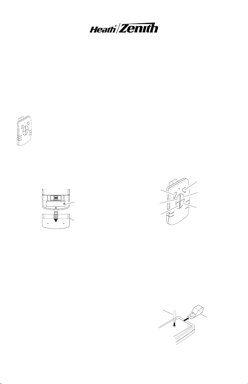
1. Install alkaline 12-Volt remote battery (A23
type). Remove cover from back of transmitter. Using outline of battery chamber as a
guide, align battery with chamber and insert
battery. Slide cover onto transmitter.
ON
1 2 3 4
Rear View of Remote Control
2. Remote Control Functions. The three buttons on the left side of the remote will operate one or more receiver units with matching
addresses. The three buttons on the right
side of the remote will operate a second set
of one or more receiver units.
• Channel 1/2 ON: Turns on any receiver unit set
to the same channel as this remote control.
• Channel 1/2 OFF: Turns off any receiver unit
• Channel 1/2 DIM: Activates the DIM feature
DRAFT COPY
set to the same channel as this remote control.
for any receiver unit set to the same channel
as this remote control.
Battery
Chamber
(Type A23)
Battery
Cover
• Products are UL/cUL and/or FCC/IC tested
and approved.
• Operational range of up to 100 feet.
Note:
To independently operate a second receiver unit using a single remote control, make
sure the 4th dip switch on each receiver is set to
different settings.
• Channel 1 - Slide dip switch 4 to the ON
position on each receiver to be operated by
these buttons.
• Channel 2 - Slide dip switch 4 to the OFF
position on each receiver to be operated by
these buttons.
Channel 1 DIM
Channel 1 ON
Channel 1 OFF
Optional Car Visor Clip (Included)
The remote control includes an optional car visor
clip for added convenience that may be installed.
1. To attach car visor clip to remote control (if
desired) push it into slot on rear of remote
unit until it snaps into place.
2. To remove car visor clip, insert a small, flat-
head screwdriver into slot on back of remote.
Gently push down on portion of visor clip
inside slot with screwdriver while pulling clip
out of remote from top.
Flat-Head
Screwdriver
FEATURES
Channel 2 DIM
Channel 2 ON
Channel 2 OFF
Function Controls
Optional
Visor Clip
Removing Visor Clip - Rear View
© 2002 DESA International 598-1116-00
RECEIVER INFORMATION
All receivers have the following features and
ratings:
• Rated for 120VAC/60Hz supply voltage.
• Light can be dimmed when used with remote
control (OFF, Low, Med, Hi, Full On).
• Remembers last selected dim setting.
• Not for use with Compact Fluorescent bulbs.
INDOOR PLUG-IN
RECEIVER
Features and Ratings:
• Up to 2.5 Amps resistive load.
• Up to 300-Watt incandescent load.
• No wiring required.
1. Plug in indoor receiver.
2. Plug in light you wish to control.
Caution: Do not exceed the maximum load
limits listed above.
3. Check operation. Either activate remote
motion sensor or toggle ON/OFF switches
on remote control to check operation.
4. Using Remote By-Pass Switch. These re-
ceivers are equipped with a remote by-pass
switch. This switch allows the user to select
between ON and RECEIVER modes. ON
mode allows the plugged in light to be operated manually. RECEIVER mode allows the
light to be operated by remote control or
remote motion sensor.
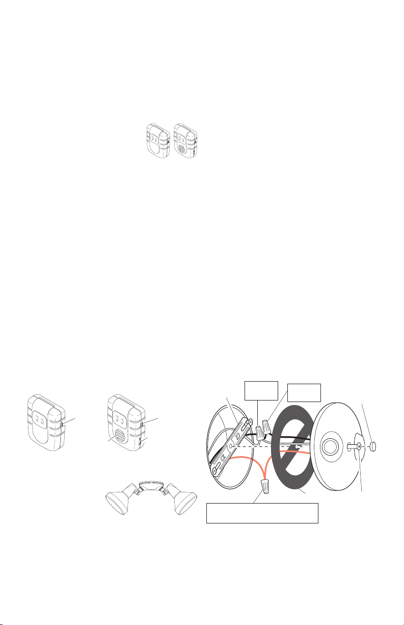
5. Adjust audio alert volume (if applicable).
Some models are equipped with an audible
alarm which sounds each time the receiver
is activated. The alarm volume is adjusted
by the thumbwheel on the side of the receiver unit.
Remote
By-Pass
Switch
Remote
By-Pass
Switch
Turn power off at the fuse or circuit breaker.
1. Remove the existing light fixture.
2. Install the mounting strap as shown using
two screws that fit your junction box.
Note:
The plastic hanger can be used to hold
the fixture while wiring. Thread the small end
of the plastic hanger through the hole in the
center of the cover plate. Insert the small end
into one of the slots on the mounting strap.
3. Route the wires from the light receiver
through the large gasket holes.
4. Twist the junction box wires and fixture
wires together as shown. Secure with UL
approved wire connectors.
5. Align the cover plate and cover plate gasket. Secure with mounting bolt.
6. Push the rubber plug firmly into place.
7. If a wet location junction box was not used,
caulk the wall plate mounting surface with
silicone weather sealant.
8. Adjust the lamp holders by loosening the lock
nuts.
Note:
more than 180° from the factory setting.
Caution: To avoid water damage and electrical shock, keep lamp holders 30° below
horizontal.
9. Screw incandescent bulb up to rated wattage into module. When screwing in the
lamps, do not overtighten.
Caution: Do not exceed the maximum load
limits listed above.
10. Check operation. Either activate remote
motion sensor or toggle ON/OFF switches
on remote control to check operation.
Mounting
Strap
Do not rotate the lamp holders
White to
White
Black to
Black
Rubber
Plug
Speaker
Control Locations
Alarm Volume
Control
DRAFT COPY
PAR LIGHT
RECEIVER
Features and
Ratings:
• Up to 300 Watt incandescent load (up to 150
Watt per lampholder).
• Minimal wiring required.
Junction box ground wire to
green ground screw on fixture.
Wiring PAR Light Receiver
2
Gasket
Mounting
Bolt
598-1116-00
 Loading...