

HeathCo 60WRC23TX Installation Manual
3-WAY WALL SWITCH TRANSMITTER
Important: This product should be used in
conjunction with the Wall Switch Receiver.
3-way circuit wiring is required to install
DIM
1. Select light switch to be replaced by 3-way wall
switch transmitter.
2. Turn off the power to the light switch circuit
before you proceed. Do this at your circuit breaker
or fuse box.
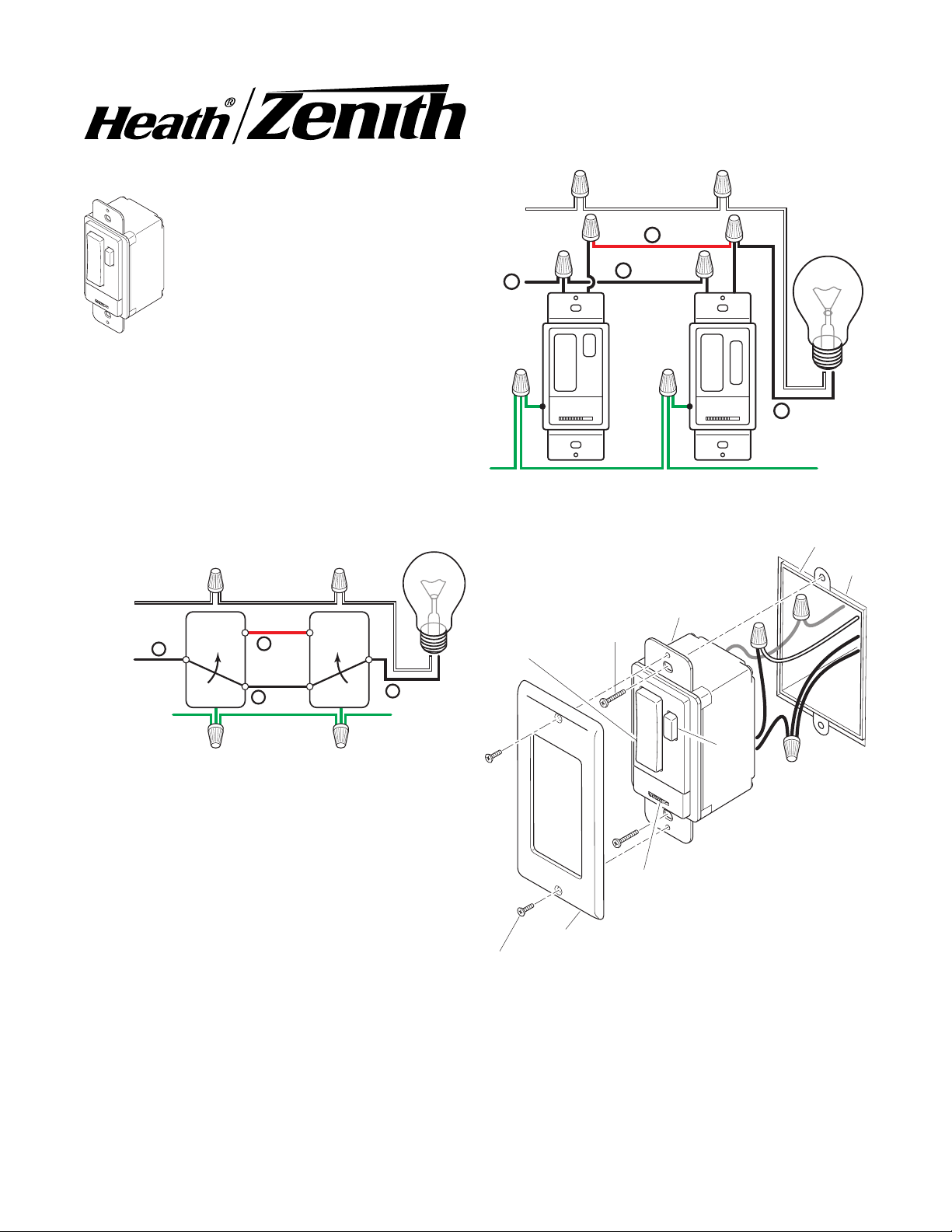
3. Remove the existing wall plate and switch. Label the
wires on the existing switch according to the diagram
in Figure 1.
Actual wiring may vary.
and use this product.
Note:
If you are not familiar with electrical
wiring, consult an electrician about installation.
In addition, some local building codes may
require installation by a qualified electrician.
Installation
Note:
Typical 3-way wiring is shown.
9. Mount the wall plate to the wall switch transmitter
with the screws (short) provided.
10. Turn on the power to the light switch circuit. Do this
at your circuit breaker or fuse box.
FROM
POWER
SOURCE
1
BLACK
(Hot)
WHITE
WHITE (Neutral)
2 RED
3 BLACK
DIM
SL-6023
GREEN (Ground)
WHITE
4 BLACK
SL-6017
Figure 2
Junction Box
FROM
POWER
SOURCE
WHITE
1
BLACK
(Hot)
GREEN
(Ground)
WHITE (Neutral) WHITE
2 RED
3 BLACK
4 BLACK
Figure 1 (Typical 3-Way Wiring Shown)
4. Disconnect the two power wires and the ground wire.
5. Connect the wires of the 3-way wall switch transmitter and wall switch receiver to the wires in the junction
box as shown in Figure 2. Use the supplied wire
connectors to secure the wires (see Figure 2).
Note:
Either black wire on the transmitter and receiver can
be used to connect to the hot wire.
6. Connect the green ground wire from transmitter to
DRAFT COPY
the ground wire removed from old switch. Use one of
the supplied wire connectors to secure the wires (see
Figure 3).
7. Check wire connections to make sure they are secure and that no bare wires are exposed.
8. Position the wall switch transmitter in the junction box
with the DIM button located to the right. Use the two
wall switch screws (long) supplied to mount the
receiver to the junction box (see Figure 3). Push
excess wiring into junction box while you do this,
bending the wires to fit if necessary.
Wall Switch
ON/OFF
Button
Cover Plate
Cover Plate Screw
Screw
Disconnect
Wall Switch
Power
Switch
Figure 3
Wall
DIM
DIM
Button

Operation
1. Verify the power disconnect switch on the transmitter
and receiver is in the ON (right side) position.
2. Push the ON (top) button and release. The light
should turn on full bright.
a lamp, make sure it is connected to the switched
outlet and the lamp is switched on.
3. Push the OFF (bottom) button and release. The light
should turn off.
4. Push the DIM button and release. The light should turn
on at 50% brightness (or last setting).
remembers the last DIM setting used. To recall last
DIM setting, push and release the DIM button.
5. Continue to press the DIM button until the desired
dim level is reached.
ranging from 15% to 90% brightness.
Note:
The DIM setting defaults to 50% in the event of a
power failure.
Important: Wait 1 to 2 seconds after you press a transmitter button before you press it again to allow the
transmission to be completed.
Note:
If light does not turn on or intermittently turns on and
off when transmitter buttons are pushed, see
shooting Guide
Move the power disconnect switch on the transmitter and
receiver to the OFF (left side) position. Replace bulb(s).
Note:
The power disconnect switch on the transmitter
prevents the unit from sending any signals to the receiver. The power disconnect switch on the receiver
prevents it from applying power to the load that it controls.
.
Bulb Replacement
Note:
If you are controlling
Note:
Note:
There are 5 DIM settings
Receiver
Trouble-
REGULATORY INFORMATION
This device complies with Part 15 of the FCC Rules and
RSS-210 of Industry Canada. Operation is subject to the
following two conditions: (1) this device may not cause
harmful interference, and (2) this device must accept any
interference received, including interference that may
cause undesired operation.
The term "IC:" before the radio certification number only
signifies that Industry Canada technical specifications
were met.
The user is cautioned that changes or modifications not
expressly approved by the party responsible for regulatory compliance could void the user’s authority to operate
the equipment.
DRAFT COPY
 Loading...