

HeathCo 60WRC14TX Users Manual
This manual includes operating instructions for a variety of remote controlled products. All products work on the same principle and use the same
Remote Controlled Products
channel setting information. Please read all instructional information and note any specific information pertaining to your particular product.
WARNINGS:
• FOR USE ONLY with 120 volt incandescent or halogen bulbs.
• DO NOT USE with fluorescent bulbs, appliances, power supplies, low voltage lighting, or any other electrical devices.
This manual applies to the following products:
•Wall Switch Transmitter
•Wall Switch Receiver
WALL SWITCH TRANSMITTER
1. Select mounting location for wall switch transmitter.
D
I
M
2. Before mounting, place transmitter in selected lo-
3. Mount transmitter to wall using two #8 x 1 3/4" wood screws
(provided). Transmitter should be mounted approximately 4
feet from the floor and in the vertical position. Use drywall
anchors (provided) if not mounting to wall stud.
1. Verify power disconnect switch on wall switch receiver is in
ON position. Wall switch transmitter will not operate lights if
power disconnect switch is in OFF position.
2. Push the ON (top) button and release. The light should turn
on full bright.
3. Push the OFF (bottom) button and release. The light should
turn off.
4. Push the DIM button and release. The light should turn on at
50% brightness (or last setting).
5. Continue to press the DIM button until the desired dim level
is reached.
To recall last DIM setting, push and release the DIM button.
Note:
The DIM setting defaults to 50% in the event of a power
failure.
Important: Wait 1 to 2 seconds after you press a transmitter
button before you press it again to allow the transmission to be
completed.
Note:
If light does not turn on or intermittently turns on and off when
transmitter buttons are pushed, see
Installation
Note:
Transmitter should be located within 100 feet
(30 m) of receiver.
cation and verify operation (see
If transmitter does not operate correctly, see
Troubleshooting Guide
Operation
).
Note:
).
Operation
Note:
DIM setting remembers last setting used.
Troubleshooting Guide
.
DRAFT COPY
• Products are UL/cUL and/or FCC/IC tested and approved.
• Operational range of up to 100 feet.
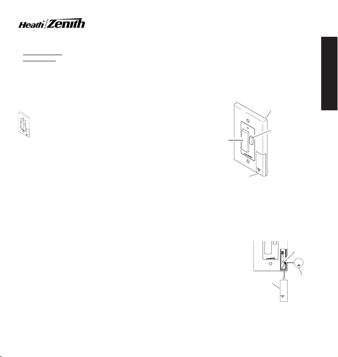
The wall switch transmitter requires a type CR2032, 3-volt
lithium battery to operate. The transmitter is shipped with the
battery installed. With typical use, the battery will last approximately one year. Remove battery when transmitter will not be
used for an extended period of time.
1. Place thumb on access
door and slide down to
open.
2. Carefully bend locking
tab outward. Battery will
pop up.
3. Remove battery from
socket.
4. Install replacement battery in socket plus (+)
side up (see illustration). Press down on
battery until locking tab
snaps into place.
5. Reinstall access door
by sliding it upward until it locks in place.
FEATURES
ON/OFF
Button
Access Door
Wall Switch Transmitter
Battery Replacement
D
I
M
Access
Removing Access Door and
Wall Switch
DIM
Button
DIM
Door
Battery
Battery
Locking
Tab
1 2 3 4
ON
m
u
B
i
h
a
t
i
t
t
L
e
r
V
y
3
2032
CR2032
Lithium
Battery
ENGLISH
© 2002 DESA International 598-1135-00
WALL SWITCH RECEIVER
Features and Ratings:
• Rated for 120VAC/60Hz supply voltage.
• Up to 300 Watt maximum incandescent load.
• Not for use with Compact Fluorescent bulbs.
• Up to 100 feet (30 m) typical transmission range.
• Fits standard single gang junction box.
Important: This product can not be used if more than one switch
is being used to control the light.
Important: Never install two wall switch receivers within 3 feet
(0.9 m) of each other. This may reduce the operating range.
1. Locate light switch to be replaced by wall switch receiver.
2. Turn off the power to the light switch circuit before you
proceed. Do this at your circuit breaker or fuse box.
3. Remove the existing wall plate and switch. Disconnect the
two power wires and the ground wire.
Note:
If there are more than two power wires attached to the
switch, consult an electrician about installation. In addition,
some local building codes may require installation by a qualified
electrician.
4. Connect one of the black power wires from receiver to one
of the power wires you removed from the old switch. Use one
of the supplied wire connectors to secure the wires (see
illustration).
5. Connect the second black power wire from receiver to the
other power wire you removed from the old switch. Use one
of the supplied wire connectors to secure the wires (see
illustration).
6. Connect the green ground wire from receiver to the ground
wire removed from old switch. Use one of the supplied wire
connectors to secure the wires (see illustration).
7. Check wire connections to make sure they are secure and
that no bare wires are exposed.
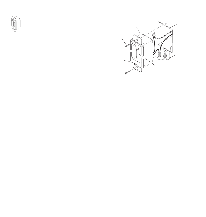
8. Position the wall switch receiver in the junction box with the
DIM button located to the right. Use the two wall switch screws
(long) supplied to mount the receiver to the wall box (see
illustration). Push excess wiring into wall box while you do this.
You may need to bend the wires to fit inside the box. Mount
wall plate on wall switch receiver with screws (short) provided.
Installation
DRAFT COPY
9. Turn on the power to the light switch circuit. Do this at your
circuit breaker or fuse box.
Wall Switch
Wall Switch
Screw
ON/OFF
Button
Power
Disconnect
Switch
Installing Wall Switch Receiver
1. Verify the power disconnect switch is in the ON (right side)
position.
2. Push the ON (top) button and release. The light should turn
on full bright.
it is connected to the switched outlet and the lamp is
switched on.
3. Push the OFF (bottom) button and release. The light should
turn off.
4. Push either the top or bottom of DIM button and release. The
light should turn on at 50% brightness (or last setting).
5. Push and release top of DIM button to increase brightness.
Push and release bottom of DIM button to decrease brightness.
90% brightness.
6. Set desired DIM level.
setting used. To recall last DIM setting, push and release
either the top or bottom of DIM button.
Note:
failure.
Move the power disconnect switch to the OFF (left side) position.
Replace bulb(s).
Caution: Do not exceed the maximum load limits listed above.
Note:
If you are controlling a lamp, make sure
Note:
There are 5 DIM settings ranging from 15% to
The DIM setting defaults to 50% in the event of a power
Bulb Replacement
DIM Button
Operation
Note:
DIM setting remembers last
Junction
Box
Ground Wire
(Bare or
Green)
2
598-1135-00
 Loading...