

HeathCo 60WRC02TX Users Manual
Multi-Channel
Remote Control
Features
A
A
L
L
O
N
ON
DIM
PA
N
IC
• Operational range of up to 100 feet.
B
A
L
L O
F
F
O
FF
• Controls all Heath®/Zenith Remote Home™ products.
• FCC/IC tested and approved.
• Flash control on compatible receivers when using the Panic
feature.
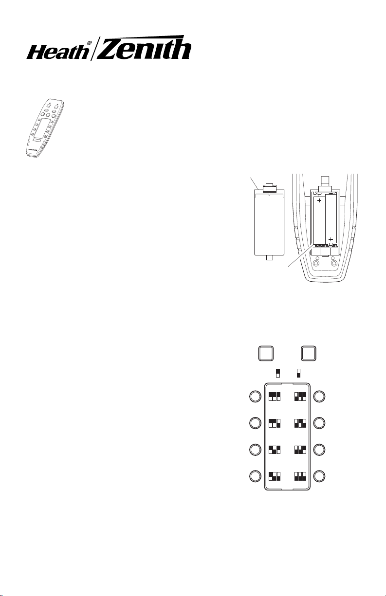
Battery Installation
Battery Cover
The Multi-Channel Remote Control is designed for 3 Volt operation:
1. Remove battery cover on rear of housing by pushing clip and lifting up.
2. Install 2-AAA batteries (not included)
according to polarity markings.
Two AAA
Batteries (Not
Included)
Installing 2-AAA Batteries
Setting Receiver(s) Dip Switches
The Control Panel transmitter has
preprogrammed dip switch settings for each
channel. In order for the Control Panel to
communicate with a receiver, the dip
switches on the receiver must correspond
with the preprogrammed dip switch settings
of the channel you wish to use.
Note:
There
are no dip switches on the Control Panel
that require setting.
1. Determine which receiver(s) will be
operated by which channel.
2. Set receiver(s) dip switches 1, 2, and 3
to match the dip switch settings for the
channel you wish to operate the
receiver(s).
DRAFT COPY
3. Determine whether the receiver(s) will
be in Group A or B.
Preprogrammed Dip Switch
Settings for Remote Control
(Included on Back of Product
4. Set dip switch 4 on the receiver to the
same setting as Group A or B.
© 2003 DESA Specialty Products™ 598-1145-00
AB
(Dip Switch 4 in
(Dip Switch 4 in
DOWN position)
1 2 3
1 2 3
1 2 3
1 2 3
GROUP
UP position)
1 2 3
1 2 3
1 2 3
1 2 3
as a Reference)
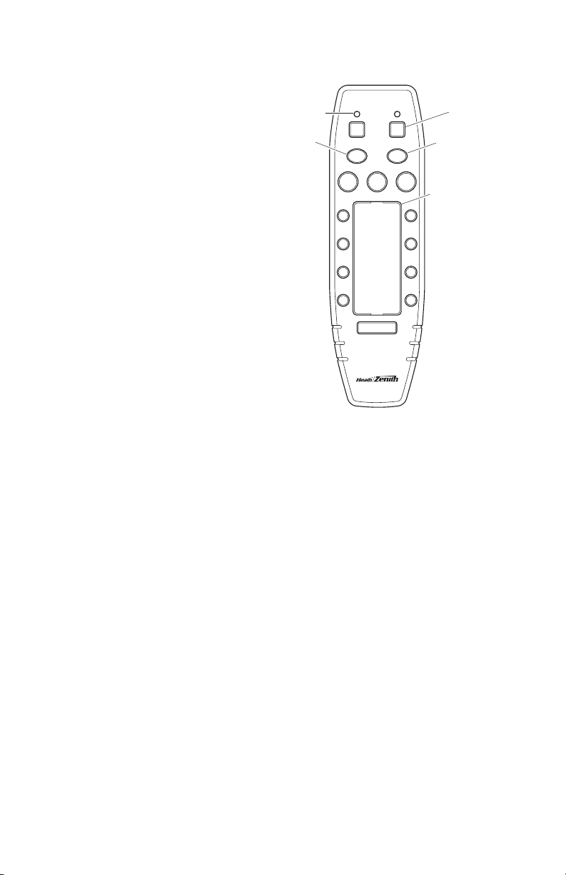
Control Descriptions
A or B GROUP: Allows each
channel to be used for 2 different groups of receivers (for
a total of 16 channels). To
choose Group A, press the
“A” button (the Group “A” indicator will be on). To choose
Group B, press the “B” button (the Group “B” indicator
will be on).
Label Channels: Remove
clear plastic film from channel label guide by placing two
fingers on the plastic and
“pinching” the plastic. Remove card. Use the decals
(included) or write on the card
to label each channel. Replace card and plastic film.
ALL ON: Turns ON all light
fixtures programmed for either Group A or Group B. Either Group A or Group B LED indicator will light as
units are turned on. To perform this function, select either Group A or Group B
then press ALL ON. If lights are off or dimmed (where applicable) they will be
turned on full power.
ALL OFF: Turns OFF all light fixtures programmed for either Group A or Group
B. Either Group A or Group B LED indicator will light as units are turned off. To
perform this function, select either Group A or Group B then press ALL OFF. If
lights are on or dimmed (where applicable) they will be turned off.
PANIC: Turns ON all light fixtures programmed for either Group A or Group B.
Light fixtures within the selected group that have Flash capability will FLASH
when this command is received. Either Group A or Group B LED indicator will
light. ALL OFF will turn off all channels within the selected group and reset all light
fixtures to normal operating mode.
Channel ON: Turns ON all light fixtures that are configured to work with a
particular channel. To perform this function, press the ON button after selecting
the channel number desired (between 1 and 8). When ON is pressed, the A or
B LED will momentarily light.
Channel OFF: Turns OFF all light fixtures that are configured to work with a
particular channel. To perform this function, press the OFF button after selecting
the channel number desired (between 1 and 8). When OFF is pressed, the A or
B LED will momentarily light.
DRAFT COPY
Group Selection
LED Indicators
ALL ON
AB
ALL ON ALL OFF
ON
DIM
PANIC
Group Selection
Group Selection
Buttons
ALL OFF
OFF
Channel
Label
Guide
2
598-1145-00
 Loading...