

Page 1
Motion-Activated LED Light
Model: 5835
Dated receipt required for warranty replacement.
FEATURES
• Bright, energy saving LED light
• DualBrite® technology
• Automatically comes on when motion is detected.
• Connect with other link technology enabled lights.
UNPACKING
Be sure to remove all contents from packaging and verify
all items are present before assembling this light xture.
is package includes the following items:
• Security Light
• Owner’s Manual
• Mounting Hardware
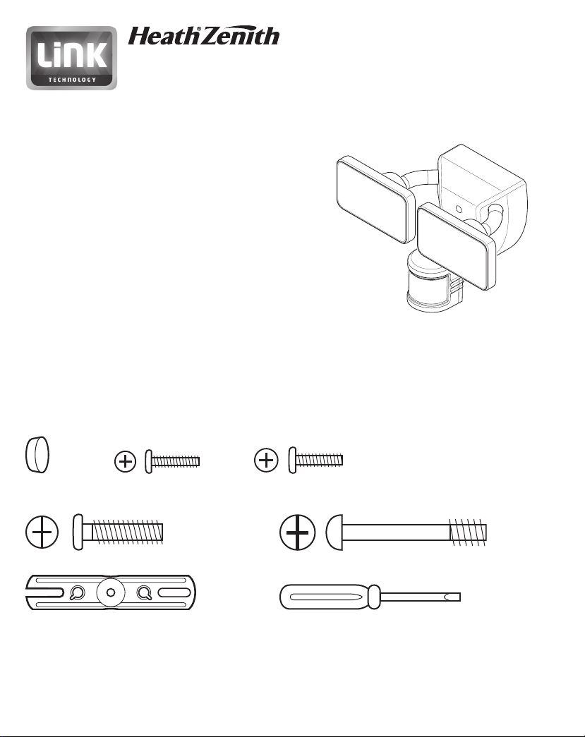
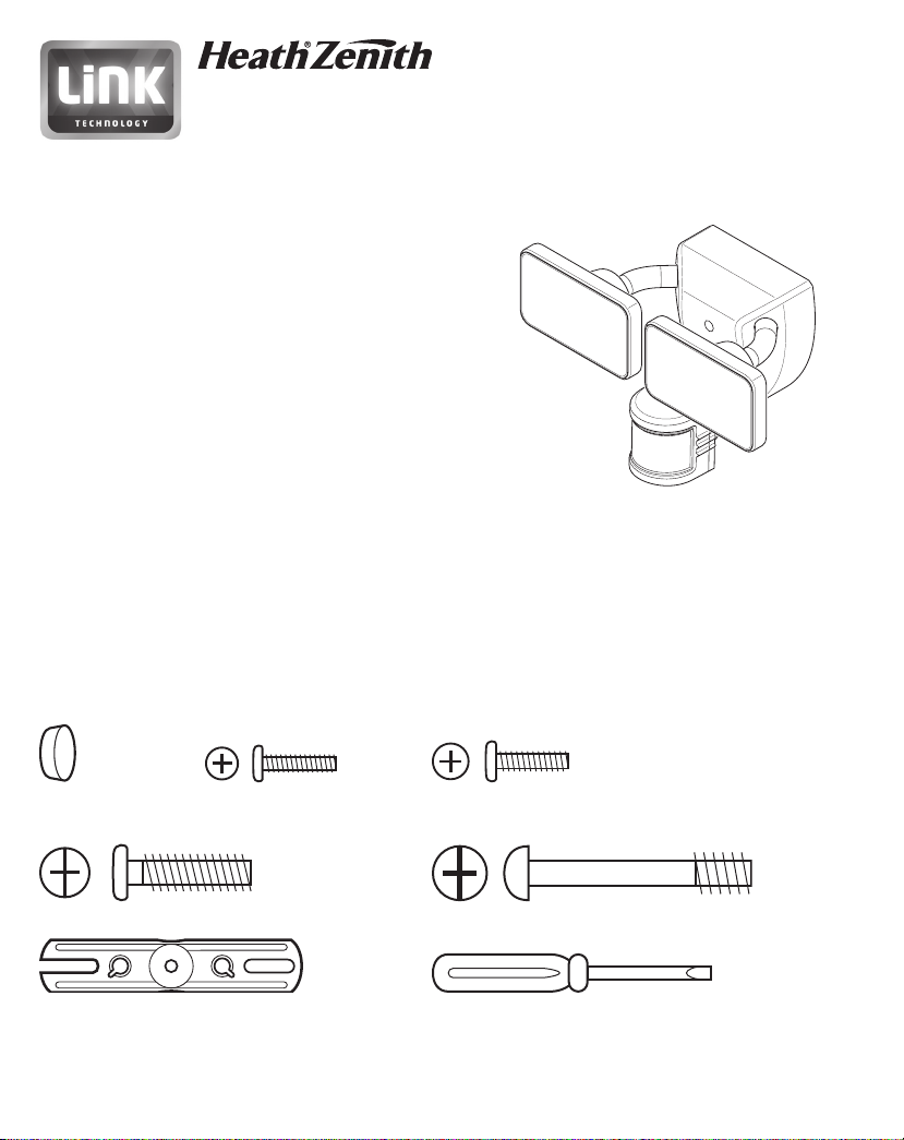
HARDWARE INCLUDED
Note: Four mounting bracket screws are included. e installation will only require two. Discard the unused mounting
bracket screws after installation.
180°
Plastic plug #6 Mounting Bracket #8 Mounting Bracket
Screw (x2) Screw (x2)
Mounting Bolt Mounting Bolt (Pre-Installed in Light Fixture)
FRONT
Mounting Bracket Mini Screwdriver
DRAFT COPY
To see operational and troubleshooting information and videos,
© 2018 HeathCo LLC 209735-01A
go to www.hzsupport.com
Page 2
IMPORTANT SAFETY AND INSTALLATION INFORMATION
A B
OFF C
L M H
4H
CHANNEL
SENS
DUALBRITE
OFF TEST
D2D
A B
OFF C
L M H
4H
CHANNEL
SENS
DUALBRITE
OFF TEST
D2D
Before installing security light, read all instructions carefully and keep owner’s manual for future reference.
• WARNING: To prevent electric shock, ensure that the power is disconnected before installation.
• WARNING: Risk of re. Keep the lamp heads at least 2 in. from combustible materials.
• CAUTION: To avoid water damage and the risk of electrical shock, the motion sensor controls must be facing the
ground when the installation is complete.
• CAUTION: Burn hazard. Allow the light xture to cool before touching.
• NOTICE: Do not connect this light xture to a dimmer switch or timer.
• is light xture requires 120-volts AC.
• is light xture must be properly grounded.
• Some electrical codes require installation by a qualied electrician.
• If you want to use Manual Mode, the light xture must be wired through a switch.
• is xture is designed for outdoor installation and should be mounted to a wall or eaves.
• To achieve best results, this xture should be mounted 8 feet (2.4 meters) above the ground. Note: If xture is mounted
higher than 8 ft. (2.4 meters), aiming the sensor down will reduce coverage distance.
• For best results, link technology enabled lights should be within 100' of each other. Obstructions such as trees, walls,
hills, etc may reduce the eective range of the link system.
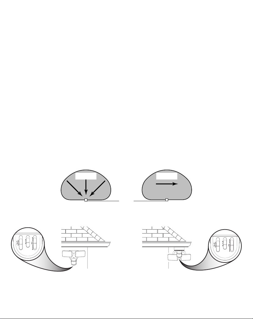
e motion sensor on this light xture detects “motion” by the movement of heat across the coverage area. e motion
sensor is more sensitive to the movement of heat moving across the coverage area and less sensitive to the movement
of heat directly towards it.
Motion Motion
Sensor
Least Sensitive Most Sensitive
THIS SIDE UP
180°
THIS SIDE UP
180°
Wall Mount Eave Mount
Note: Light xture and sensor should be mounted as shown above when installed (depending upon type of installation).
2 To see operational and troubleshooting information and videos,
go to www.hzsupport.com
209735-01
Page 3
INSTALLATION
FRONT
UP/Haut/Arriba
UP/Haut/Arriba
WARNING: Turn power o at circuit breaker or fuse.
Place tape over circuit breaker switch and verify power is
o at the xture.
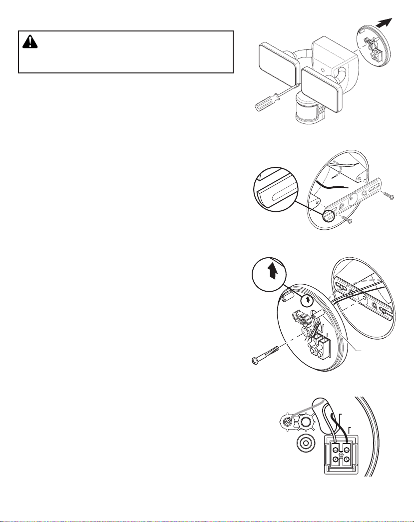
is xture comes with a “Easy Install” mounting plate. It is preassembled on the xture for shipping.
1. From the front of the light xture, unscrew the large mounting
bolt connecting the light xture to the mounting plate and remove
the mounting plate (see Figure 1). e mounting bolt is designed
to stay in the light xture.
2. Install the mounting bracket with the stamped word “FRONT”
facing away from the junction box (see Figure 2). Use the mounting bracket screws that best t the junction box.
3. Route the junction box wires through the hole in the mounting
plate (see Figure 3).
4. Place the mounting plate against the junction box (see Figure3).
• Wall Mounted – e “UP” arrow must point upward
• Eave Mounted – e “UP” arrow must point toward the building
5. Insert the small mounting bolt through the mounting plate hole
located below the threaded hole. read the bolt into the center
hole of the mounting bracket (see Figure 3). Tighten bolt securely.
WIRING
Insert the junction box wires into the side of the terminal block and
around the ground screw (see Figure 4). Tighten terminal block screws
and ground screw to secure wires.
• White to “N (White)”
• Black to “L (Black)”
• Bare or green ground wire to GND (ground) screw.
FINAL ASSEMBLY
1. Double check that all wiring connections are securely connected.
2. Align the two alignment posts on the mounting plate (see Figure
3) with the two alignment holes on the rear of the light xture
and press the light xture onto the mounting plate.
IMPORTANT: e two metal pins on the rear of the light xture
must insert into the terminal block for the light to work.
3. Tighten the mounting bolt securely being careful not to overtighten
(see Figure 5).
GND
Terre
Tierra
180°
Figure 1
FRONT
Figure 2
UP/Haut/Arriba
GND
Terre
Tierra
N (White/
Blanc/Blanco)
L (Black/
Noir/Negro)
FRONT
Alignment
Post
Figure 3
N (White/
Blanc/Blanco)
L (Black/
Noir/Negro)
Figure 4
209735-01
To see operational and troubleshooting information and videos, 3
go to www.hzsupport.com
Page 4
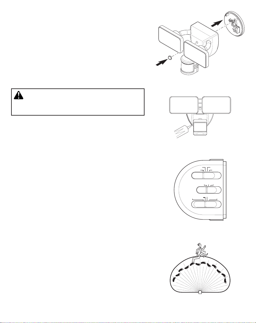
IMPORTANT:
• If wall mounted, make sure the xture is mounted with the
sensor below the lamp heads.
• If eave mounted, mount the xture with sensor facing away
from the house wall. Rotate the sensor so the controls face the
ground.
4. Push the rubber plug rmly into the mounting bolt hole on the
light xture (see Figure 5).
5. Caulk around mounting plate and mounting surface with silicone
weather sealant (see Figure 6).
180°
TESTING AND ADJUSTMENTS
CAUTION: To avoid water damage and risk of electrical
shock, motion sensor controls must be facing the ground
when installation is complete.
1. Turn on the circuit breaker and wall switch.
Note: e motion sensor has a 1 minute warm up period before it
will detect motion. When power is rst turned on wait 1 minute.
2. Slide the CHANNEL switch to OFF, the sensitivity (SENS)
switch to the “L” position, and the DUALBRITE switch to the
TEST position (see Figure 7). Note: e TEST mode overrides
the photocell (daylight shuto feature) and allows the light xture
to be tested day or night.
3. Walk through the coverage area noting where you are when the
lights turn on. Also, the red LED behind the motion sensor lens
will ash several times when motion is detected (see Figure 8).
4. Stop, wait for the light to turn o (8 seconds), and then begin
walking again. Continue this process until the detection zone has
been established.
5. If needed, gently grasp the motion sensor and move it from side
to side or up and down to adjust the detection zone.
6. If needed, gently grasp the lamp heads and move them from side
to side or up and down to adjust the light coverage area.
7. Adjust the sensitivity (SENS) switch as needed (“L”, “M”, “H”).
Sensitivity set too high may increase false triggering.
LINKING LIGHTS
is light has been designed with link technology which allows
multiple lights to be connected together wirelessly. Linked lights
can be grouped into one of three possible channels to create linked
zones of lighting. See
1. Slide the CHANNEL switch to the desired channel (A, B, or
C) on all lights to be linked together.
2. Slide the DUALBRITE switch to the TEST position on all of
4 To see operational and troubleshooting information and videos,
Link Technology
section for more information.
go to www.hzsupport.com
Figure 5
Figure 6
OFF C
OFF TEST
Figure 7
Figure 8
A B
L M H
4H
CHANNEL
SENS
D2D
DUALBRITE
209735-01
Page 5
the selected lights. Note: e TEST mode overrides the photocell (daylight shuto feature) and allows the light
xture to be tested day or night.
3. Walk in front of each light to ensure all linked lights are activated from another linked light. Note: e linked lights
may not come on at the same time because of the delay of the transmission signal.
FINAL SETUP
1. W hen testing is complete, set the DUALBRITE switch to the desired amount of time after dusk the lights should remain
on at a reduced light level [O, 4 Hrs., Dusk-to-Dawn (D2D)]. See DualBrite Timer section for more information.
2. e amount of time the lights stay on after ALL motion has stopped in front of ALL linked lights is preset to 5 minutes.
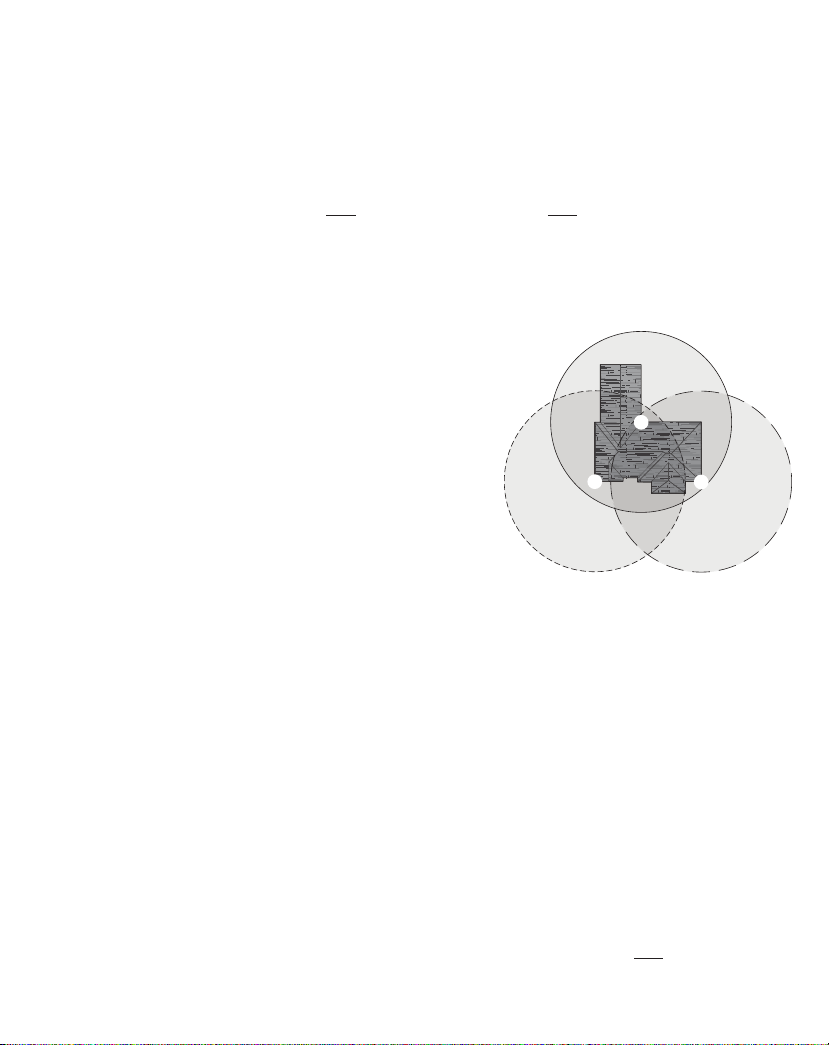
IMPORTANT CONSIDERATIONS
LINK TECHNOLOGY:
Link technology allows multiple lights to be connected together wirelessly. When one light senses motion it will turn on
full bright and send out a wireless signal. All lights within range and on the same channel will also turn on full bright.
Each time a light receives a signal, it will then repeat the signal so
other lights not in range of the rst light will also turn on full bright.
Linked lights can be grouped into one of three possible channels (A,
B, or C) to create linked zones of lighting. Note: Linked lights turn
o independently of each other and may not turn o at exactly the
same time.
Illustration example:
Light #1 senses motion and sends a signal. Light
#2 is out of range of light #1 and does not receive the signal. Light #3
is in range of light #1 and receives the activation signal. Light #3 is
activated and repeats the signal. Light #2 is in range of light #3 and is
activated. Note: All the lights will send out a signal when activated, even
if the light’s DualBrite switch is set to OFF. If the light is in manual
mode, it will repeat any signal it receives but will not initiate a signal.
AVOID AIMING THE SENSOR AT:
• Below are examples of objects that might produce heat and may cause the motion sensor to trigger:
• Pools of Water • Air Conditioners • Dryer Vents
• Animals • Heating Vents • Automobile Trac
If you suspect that a heat source of this type is triggering the motion sensor, reduce the sensitivity.
• Areas where pets or trac may trigger the motion sensor.
• Nearby large, light-colored objects reecting light may trigger the shut-o feature. Do not point other lights at the
motion sensor.
SEASONAL CHANGES:
e motion sensor works by sensing temperature changes across its eld of view. e closer the surrounding temperature is to a person’s body heat, the less sensitive the sensor will appear. e greater the temperature dierence, the more
sensitive the sensor will appear. e sensitivity (SENS) switch might need to be readjusted as the outside temperature
changes for the dierent seasons. is is a normal part of the light sensor’s operation.
3
2
1
DUALBRITE TIMER
DualBrite mode is a selectable feature that turns the light on at dusk in a reduced light level. e light will stay on at
the reduced light level for the amount of time selected [O, 4 hr., dusk-to-dawn (D2D)]. When motion is detected, the
light will increase to full bright. e light will stay on at the full bright level for 5 minutes after
209735-01
To see operational and troubleshooting information and videos, 5
go to www.hzsupport.com
ALL
motion has stopped
Page 6
in front of
the light will turn ON only when motion is detected by any of the linked lights. Selecting OFF disables the DualBrite
feature, however the motion sensing features will continue to work.
For linked lights, the rst light to sense darkness will turn on all other linked lights on the same channel if the DualBrite
timer has been turned ON on each linked light. e lights will turn OFF independently of each other and may not turn
OFF at exactly the same time.
ALL
linked lights. e light will then return to the reduced light level. Once the DualBrite timer runs out,
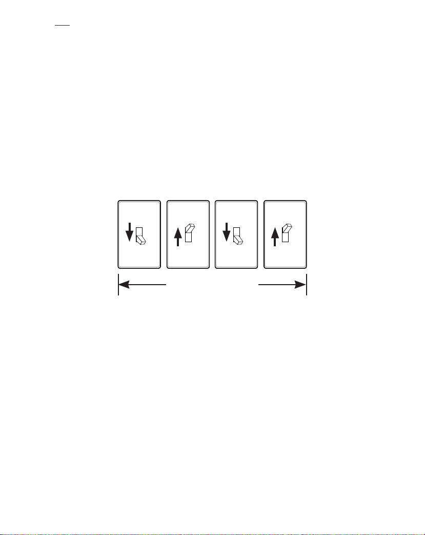
MANUAL MODE
Manual mode overrides the motion sensor and “ON-TIME” control so the light will operate full bright. is feature
only works at night and only for one night at a time. e motion sensor will reset to motion sensing mode after 6 hours
or sunrise, whichever comes rst. Manual mode can be toggled on and o using a wall switch. Note: If the power to the
light xture is o for more than 5 seconds, allow the motion sensor to warm up prior to switching to manual mode.
1. Ensure the power to the light is ON and the sensor has warmed up (60 seconds).
2. To turn manual mode on, switch the power OFF–ON–OFF–ON at the wall switch within 5 seconds.
3. To turn manual mode o, switch the power OFF–ON–OFF–ON at the wall switch within 5 seconds.
IMPORTANT: If manual mode does not turn ON or OFF, use a slower pace turning the power ON and OFF at the wall
switch while staying within 5 seconds.
OFF OFFON ON
Less than 5 seconds
CARE AND CLEANING
• To prolong the original appearance, clean the light xture with clear water and a soft, damp cloth only.
• Do not use paints, solvents, or other chemicals on this light xture. ey could cause a premature deterioration of the
nish. is is not a defect in the nish and will not be covered by the warranty.
• Do not spray the light xture with a hose or power washer.
• To clean the camera lens, use a dry, microber cloth only.
SPECIFICATIONS
Range ...................................................Up to 70 ft. (21 m) [varies with surrounding temperature].
Sensing Angle.......................................Up to 180°
Power Requirements .............................120 VAC, 60 Hz
Operating Modes .................................TEST, MOTION ACTIVATED, and MANUAL MODE
ON-Timer ............................................5 minutes (non-adjustable)
Test Timer ............................................8 Seconds
Manual Mode Timer ............................Maximum 6 Hours
Sensitivity (SENS) ...............................“L”, “M”, “H”
Link Technology Range .......................Up to 100 ft (30.5 m) [varies with surrounding obstructions].
6 To see operational and troubleshooting information and videos,
go to www.hzsupport.com
209735-01
Page 7

TROUBLESHOOTING GUIDE
SYMPTOM POSSIBLE CAUSE SOLUTION
e light will not come on. 1. Light switch is turned o.
e light comes on during
the day.
e light comes on for no
apparent reason.
e lights turn o too late
in dusk-to-dawn (D2D)
setting.
e lights stay on
continuously.
2. Fuse is blown or circuit breaker is turned o.
3. Daylight turn-o (photocell) is in eect.
4. e circuit wiring is incorrect, if this is a new
installation.
5. e motion sensor is aimed in the wrong
direction.
6. e outside air temperature is close to the
same as a person’s body heat.
1. e motion sensor may be installed in a
relatively dark location.
2. e “DUALBRITE” switch is in the
“TEST” position.
1. e motion sensor may be sensing small
animals or automobile trac.
2. e “SENS” switch is set too high.
3. e “DUALBRITE” switch is in the 4 hour
or dusk-to-dawn (D2D) setting.
4. e light xture is linked to another light.
5. e light xture is on the same channel as a
neighbor’s linked light xture.
6. e outside temperature is much warmer or
cooler than a person’s body heat (summer or
winter).
7. e light xture is wired through a dimmer
or timer.
e light xture may be installed in a relatively
dark location.
1. e motion sensor may be picking up a heat
source like an air vent, dryer vent, or brightly
painted, heat-reective surface.
2. e motion sensor is in manual mode.
3. A linked light xture is picking up
continuous motion and is keeping all linked
lights on.
4. Motion is being detected by multiple linked
lights and is keeping all linked lights on.
5. e light xture is wired through a dimmer
or timer.
6. e light xture is on the same circuit as a
motor, transformer, or uorescent bulb.
1. Turn light switch on.
2. Replace fuse or turn circuit breaker on.
3. Recheck after dark.
4. Verify wiring is correct.
5. Re-aim the motion sensor to cover the
desired area.
6. Increase the “SENS” setting. See
Changes
1. e light xture is operating normally under
these circumstances.
2. Set the “DUALBRITE” switch to the OFF, 4
hour, or dusk-to-dawn (D2D) setting.
1. Decrease the “SENS” setting or reposition
the motion sensor.
2. Decrease the “SENS” setting.
3. e light xture is operating normally under
these circumstances.
4. e light xture is operating normally if
linked. e link option can be turned OFF or
set to a dierent channel.
5. Change the channel of the aected light
xtures to a dierent channel.
6. Decrease the “SENS” setting. See
Changes
7. Do not use a dimmer or timer to control the
light xture. Replace the dimmer or timer
with a standard on/o wall switch.
Relocate the light xture or use the 4 hour
setting.
1. Decrease the “SENS” setting or reposition
the motion sensor.
2. Follow
to reset.
3. e light xtures are operating normally
under these circumstances.
4. e light xtures are operating normally
under these circumstances.
5. Do not use a dimmer or timer to control the
light xture. Replace the dimmer or timer
with a standard on/o wall switch.
6. Install the light xture on a circuit without
motors, transformers, or uorescent bulbs.
on page 5 for more information.
on page 5 for more information.
Manual Mode
instructions on page 6
Seasonal
Seasonal
209735-01
To see operational and troubleshooting information and videos, 7
go to www.hzsupport.com
Page 8

SYMPTOM POSSIBLE CAUSE SOLUTION
e lights ash on and o. 1. Heat or light from the lamp heads may be
e lights ash once then
stay o in manual mode.
turning the motion sensor on and o.
2. Heat is being reected from other objects
and may be turning the motion sensor on
and o.
3. e motion sensor is in “TEST” mode and
warming up.
e motion sensor is detecting light from the
lamp heads.
1. Reposition the lamp heads away from the
motion sensor.
2. Decrease the “SENS” setting or reposition
the motion sensor.
3. While in “TEST” mode, the light only stays
on for 8 seconds. Set the “DUALBRITE”
switch to OFF, 4 hour, or dusk-to-dawn
(D2D).
Reposition the lamp heads to keep the area below
the motion sensor relatively dark.
TECHNICAL SERVICE
Please call 1-800-858-8501 (English speaking only) for assistance before returning product to
store.
If you experience a problem, follow this guide. You may also want to visit our Web site at: www.hzsupport.com. If the
problem persists, call* for assistance at 1-800-858-8501 (English speaking only), 8:00 AM to 5:00 PM CST (M-F).
You may also write* to:
HeathCo LLC
P.O. Box 90045
Bowling Green, KY 42102-9045
ATTN: Technical Service
* If contacting Technical Service, please have the following information available: Model Number, Date of Purchase,
and Place of Purchase.
No Service Parts Available for this Product
Please keep your dated sales receipt, it is required for all warranty requests.
8 To see operational and troubleshooting information and videos,
go to www.hzsupport.com
209735-01
Page 9

FIVE YEAR LIMITED WARRANTY
is is a “Limited Warranty” which gives you specic legal rights. You may also have other rights which vary from
state to state or province to province.
For a period of ve years from the date of purchase, any malfunction caused by factory defective parts or workmanship will be corrected at no charge to you.
Not Covered - Repair service, adjustment and calibration due to misuse, abuse or negligence, light bulbs, batteries,
and other expendable items are not covered by this warranty. Any damage to the light xture resulting from the use
of chemicals or a pressure washer machine are not covered by this warranty. Unauthorized service or modication
of the product or of any furnished component will void this warranty in its entirety. is warranty does not include
reimbursement for inconvenience, installation, setup time, loss of use, unauthorized service, or return shipping charges.
is warranty covers only HeathCo LLC assembled products and is not extended to other equipment and components that a customer uses in conjunction with our products.
THIS WARRANTY IS EXPRESSLY IN LIEU OF ALL OTHER WARRANTIES, EXPRESS OR IMPLIED,
INCLUDING ANY WARRANTY, REPRESENTATION OR CONDITION OF MERCHANT ABILITY
OR THAT THE PRODUCTS ARE FIT FOR ANY PARTICULAR PURPOSE OR USE, AND SPECIFICALLY IN LIEU OF ALL SPECIAL, INDIRECT, INCIDENTAL, OR CONSEQUENTIAL DAMAGES.
REPAIR OR REPLACEMENT SHALL BE THE SOLE REMEDY OF THE CUSTOMER AND THERE
SHALL BE NO LIABILITY ON THE PART OF HEATHCO LLC FOR ANY SPECIAL, INDIRECT,
INCIDENTAL, OR CONSEQUENTIAL DAMAGES, INCLUDING BUT NOT LIMITED TO ANY
LOSS OF BUSINESS OR PROFITS, WHETHER OR NOT FORESEEABLE. Some states or provinces do
not allow the exclusion or limitation of incidental or consequential damages, so the above limitation or exclusion
may not apply to you.
Please keep your dated sales receipt, it is required for all warranty requests.
HeathCo LLC reserves the right to discontinue products and to change specications at any time without incurring any
obligation to incorporate new features in products previously sold.
is device complies with Part 15 of the FCC Rules. Operation is subject to the following two conditions: (1) this device
may not cause harmful interference, and (2) this device must accept any interference received, includ-ing interference
that may cause undesired operation.
CAN ICES-005 (B)/NMB-005 (B)
Note: is equipment has been tested and found to comply with the limits for aClass B digital device, pursuant to
part 15 of the FCC Rules. ese limits are designed to provide reasonable protection againstharmful interferencein a
residential installation. is equipment generates, uses and can radiateradio frequency energyand, if not installed and
used in accordance with the instructions, may causeharmful interferenceto radio communications. However, there is no
guarantee that interference will not occur in a particular installation. If this equipment does causeharmful interferenceto
radio or television reception, which can be determined by turning the equipment o and on, the user is encouraged to
try to correct the interference by one or more of the following measures:
- Reorient or relocate the receiving antenna.
- Increase the separation between the equipment and receiver.
- Connect the equipment into an outlet on a circuit dierent from that to which the receiver is connected.
- Consult the dealer or an experienced radio/TV technician for help.
209735-01
To see operational and troubleshooting information and videos, 9
go to www.hzsupport.com
Page 10
Luz LED activada
por movimiento
Modelo: 5835
Se necesita el recibo fechado para reemplazo bajo garantía.
CARACTERÍSTICAS
• Luz LED brillante de bajo consumo de energía
• Tecnología DualBrite®
• Se enciende automáticamente al detectar movimiento.
• Conecte con las otras luces activadas con tecnología de
interconexión.
DESEMPAQUE
Asegúrese de retirar todo el contenido del empaque y
vericar que todos los elementos estén incluidos antes de
ensamblar este aparato de luz. Este paquete incluye los
siguientes elementos:
• Luz de seguridad
• Manual del propietario
• Ferretería de montaje
FERRETERÍA INCLUIDA
Nota: Se incluyen cuatro tornillos para el soporte de montaje. La instalación sólo requiere dos. Deseche los tornillos del
soporte de montaje no utilizados luego de la instalación.
180°
Enchufe de Tornillo n°6 de soporte Tornillo n°8 de soporte
plástico de montaje (x2) de montaje (x2)
Tornillo de montaje Tornillo de montaje (Preinstalado en el aparato)
FRONT
Soporte de montaje Mini-destornillador
10 Para ver más información y vídeos sobre operación y resolución de problemas,
© 2018 HeathCo LLC 209735-01 S
visite www.hzsupport.com
209735-01
Page 11

INFORMACIÓN IMPORTANTE DE SEGURIDAD E INSTALACIÓN
A B
OFF C
L M H
4H
CHANNEL
SENS
DUALBRITE
OFF TEST
D2D
A B
OFF C
L M H
4H
CHANNEL
SENS
DUALBRITE
OFF TEST
D2D
Antes de instalar la luz de seguridad, lea todas las instrucciones con cuidado y guarde el manual del propietario para
futura referencia.
• ADVERTENCIA: Para evitar descargas eléctricas, asegúrese de que la alimentación esté desconectada antes de la instalación.
• ADVERTENCIA: Riesgo de incendio. Mantenga las bombillas alejadas al menos 2 pulgadas (51mm) de materiales
combustibles.
• PRECAUCIÓN: Para evitar daños por el agua y el riesgo de una descarga eléctrica, los controles del detector de movimiento deben estar de cara al suelo cuando la instalación esté terminada.
• PRECAUCIÓN: Peligro de quemaduras. Deje que el aparato de luz se enfríe antes de tocarlo.
• AVISO: No conecte este aparato de luz a un interruptor reductor de luz ni a un temporizador.
• Este aparato de luz requiere 120 voltios CA.
• Este aparato de luz debe estar correctamente conectado a tierra.
• Algunas normativas eléctricas exigen que la instalación la realice un electricista calicado.
• Si desea utilizar la fase Manual, la lámpara debe estar conectada a través de un interruptor.
• Este aparato está diseñado para una instalación al aire libre y se lo debe montar en una pared o en aleros.
• Para lograr los mejores resultados, este aparato debe montarse a 8 pies (2,4 metros) por encima del suelo. Nota: Si el
aparato está instalado a más de 8 pies (2,4 m), si se apunta el detector hacia abajo se reducirá la distancia de cobertura.
• Para obtener los mejores resultados, las luces activadas con tecnología de interconexión deben estar dentro de 100 pies
entre ellas. Las obstrucciones tales como árboles, paredes, colinas, etc. pueden reducir el alcance efectivo del sistema
de interconexión.
El detector de movimiento de este aparato de luz detecta “movimiento” debido al movimiento del calor a través del
área de cobertura. El detector de movimiento es más sensible a la circulación del calor que se mueve a través del área de
cobertura y menos sensible a la circulación del calor que va directamente hacia él.
Movimiento Movimiento
Detector
Lo menos sensible Lo más sensible
THIS SIDE UP
180°
THIS SIDE UP
180°
Montaje en pared Montaje en alero
Nota: La lámpara y el sensor debe montarse como se indica arriba, una vez instalado (según el tipo de instalación).
209735-01
Para ver más información y vídeos sobre operación y resolución de problemas, 11
visite www.hzsupport.com
Page 12

INSTALACIÓN
FRONT
UP/Haut/Arriba
UP/Haut/Arriba
ADVERTENCIA: Desconecte la energía en el fusible
o cortacircuitos. Coloque cinta encima del interruptor de
cortacircuitos y verique que la energía está apagada en
la luminaria.
Este dispositivo viene con una placa de montaje “Easy Install”(conexión
rápida). Está pre-instalado en el aparato para ser enviado.
1. De la parte delantera de la lámpara, desenrosque el tornillo grande
de montaje que conecta la lámpara a la placa de montaje y retire
la placa de montaje (ver Figura 1). El tornillo de montaje está
diseñado para permanecer en la lámpara.
2. Instale el soporte de montaje con la palabra estampada “FRONT”
de espaldas a la caja de conexiones (vea la Figura 2). Use los
tornillos del soporte de montaje que mejor se adapten a la caja
de conexiones.
3. Pase los cables de la caja de conexiones por el agujero que está
en la placa de montaje (vea la Figura 3).
4. Coloque la placa de montaje contra la caja de conexiones (vea la
Figura 3).
• Montaje en pared - La echa “UP” debe apuntar hacia arriba.
• Montaje en alero - La echa “UP” debe apuntar hacia el edicio.
5. Inserte el tornillo pequeño de montaje por el agujero de la placa
de montaje situado debajo del agujero roscado. Enrosque el perno
en el oricio central del soporte de montaje (ver Figura 3). Apriete
el perno de forma segura.
CABLEADO
Inserte los cables de la caja de conexiones en el lado del bloque de
GND
Terre
Tierra
terminales y al rededor del tornillo de tierra (ver la Figura 4). Apriete los tornillos del bloque de terminales y el tornillo de tierra para
asegurar los cables.
• Blanco con “N (blanco)”
• Negro con “L (negro)”
• Alambre desnudo o verde con el tornillo GND (tierra)
MONTAJE FINAL
1. Asegúrese de que todas las conexiones de los cables estén bien
conectadas.
2. Alinee los dos postes de alineación en la placa de montaje (vea
la Figura 3) con los dos oricios de alineación en la parte trasera
de la lámpara y presione la lámpara sobre la placa de montaje.
IMPORTANTE: Las dos clavijas de metal en la parte trasera de
la lámpara deben insertarse en el bloque de terminales para que
la luz funcione.
12 Para ver más información y vídeos sobre operación y resolución de problemas,
visite www.hzsupport.com
GND
Terre
Tierra
180°
UP/Haut/Arriba
Figura 1
FRONT
Figura 2
N (White/
Blanc/Blanco)
Figura 3
Figura 4
L (Black/
Noir/Negro)
N (White/
Blanc/Blanco)
L (Black/
Noir/Negro)
FRONT
Poste de
alineación
209735-01
Page 13

3. Apriete bien el tornillo de montaje teniendo cuidado de no
apretarlo demasiado (vea la Figura 5).
IMPORTANTE:
• Si lo monta en la pared, asegúrese de que el aparato esté
montado con el detector debajo de las cabezas de la lámpara.
• Si lo monta en un alero, monte el aparato con detector de
espaldas a la pared de la casa. Gire el detector de manera que
los controles miren hacia el suelo.
4. Empuje con fuerza el tapón de caucho en el oricio del perno de
montaje de la lámpara (vea la Figura 5).
5. Calafatee alrededor de la placa de montaje y de la supercie de
montaje con un sellador de silicona (vea la Figura 6).
PRUEBAS Y AJUSTES
PRECAUCIÓN: Para evitar daños por el agua y el riesgo
de una descarga eléctrica, los controles del detector de movimiento deben estar de cara al suelo cuando la instalación
esté terminada.
180°
Figura 5
1. Encienda el disyuntor y el interruptor de pared.
Figura 6
Nota: El detector de movimiento tiene un período de 1 minuto
de calentamiento antes de detectar movimiento. Cuando encienda
la alimentación por primera vez espere 1 minuto.
2. Deslice el interruptor CHANNEL a OFF, el interruptor de
sensibilidad (SENS) a la posición "L", y el interruptor DUALBRITE a la posición TEST (vea la Figura 7). Nota: La fase de
prueba (TEST) anula la fotocélula (función de apagado de la luz
del día) y permite que la lámpara sea probada durante el día o la
noche.
OFF C
OFF TEST
A B
L M H
4H
CHANNEL
SENS
D2D
3. Camine por el área de cobertura y note dónde está usted cuando
las luces se encienden. Además, la LED roja detrás de la lente del
DUALBRITE
detector de movimiento destellará varias veces cuando se detecta
movimiento (vea la Figura 8).
4. Deténgase, espere que la luz se apague (8 segundos), y luego
Figura 7
empiece a caminar de nuevo. Continúe este proceso hasta que la
zona de detección haya sido establecida.
5. Si es necesario, sujete suavemente el detector de movimiento y
muévalo de lado a lado o de arriba hacia abajo para ajustar la zona
de detección.
6. Si es necesario, sujete suavemente los cabezales de la lámpara y
muévalas de lado a lado o de arriba hacia abajo para ajustar el
área de cobertura de la luz.
7. Ajuste el interruptor de sensibilidad (SENS), según sea necesario
(“L”, “M”, “H”). Una sensibilidad demasiado alta puede aumentar
las falsas alarmas.
209735-01
Para ver más información y vídeos sobre operación y resolución de problemas, 13
visite www.hzsupport.com
Figura 8
Page 14

LUCES DE INTERCONEXIÓN
Esta luz ha sido diseñada con tecnología de interconexión que permite la conexión de múltiples luces entre sí en forma
inalámbrica. Las luces de interconexión se pueden agrupar en uno de tres posibles canales para crear zonas interconectadas
de iluminación. Vea la sección de
Tecnología de interconexión
para más información.
1. Deslice el interruptor de CANAL (CHANNEL) al canal deseado (A, B, o C) en todas las luces que deben estar
interconectadas entre sí.
2. Deslice el interruptor DUALBRITE a la posición de prueba (TEST) en todas las luces seleccionadas. Nota: La fase
de prueba anula la fotocélula (función de apagado de la luz del día) y permite que la lámpara sea probada durante el
día o la noche.
3. Camine por delante de cada luz para asegurarse de que todas las luces interconectadas son activadas desde otra luz
de interconexión. Nota: Las luces interconectadas pueden no prenderse al mismo tiempo, debido a la demora de la
señal de transmisión.
REGULACIÓN FINAL
1. Cuando termine la prueba, ajuste el interruptor DUALBRITE a la cantidad deseada de tiempo, después del anochecer, que las luces deben permanecer prendidas a un nivel reducido [O, 4 Hrs., anochecer al amanecer (D2D)].
Vea la sección
2. La cantidad de tiempo que las luces permanecen encendidas después de que
frente a
Temporizador DualBrite
TODAS
las luces interconectadas está preestablecido a 5 minutos.
para más información.
TODO
movimiento se ha detenido
CONSIDERACIONES IMPORTANTES
TECNOLOGÍA DE INTERCONEXIÓN:
La tecnología de interconexión que permite la conexión de múltiples luces entre sí en forma inalámbrica Cuando una
luz detecta movimiento se encenderá con todo su resplandor y enviará una señal inalámbrica. Todas las luces dentro de
ese alcance y en el mismo canal también se encenderán con todo su resplandor. Cada vez que una luz recibe una señal,
repetirá la señal para que otras luces que no están dentro del alcance de la primera luz también se encenderán con todo
su resplandor. Las luces de interconexións se pueden agrupar en uno
de tres posibles canales (A, B, o C) para crear zonas interconectadas
de iluminación. Nota: Las luces interconectadas se apagan independiente la una de la otra y puede que no se apaguen exactamente al
mismo tiempo.
Ejemplo de ilustración:
La luz # 1 detecta movimiento y envía una
señal. La luz # 2 está fuera del alcance de la luz # 1 y no recibe la
señal. La luz # 3 está dentro del alcance de la luz # 1 y recibe la señal
de activación. La luz # 3 se activa y se repite la señal. La luz # 2 está
dentor del alcance de la luz # 3 y se activa. Nota: Todas las luces enviarán una señal cuando se activan, incluso si el interruptor de la luz
DUALBRITE está en OFF. Si la luz está en fase manual, repetirá
cualquier señal que recibe, pero no la iniciará.
EVITE APUNTAR EL DETECTOR A:
• A continuación hay ejemplos de objetos que pueden producir calor y pueden causar que el detector de movimiento se
active:
• Pozos de agua • Acondicionadores de aire • Ventosas de la secadora
• Animales • Ventosas de calefacción • Tráco de carros
Si sospecha que una fuente de calor de este tipo está activando el detector de movimiento, reduzca la sensibilidad.
3
2
1
14 Para ver más información y vídeos sobre operación y resolución de problemas,
visite www.hzsupport.com
209735-01
Page 15

• Zonas donde animales domésticos o el tráco puedan activar el detector de movimiento.
• Los objetos grandes cercanos y de colores resplandecientes que reejan la luz del día pueden hacer que el detector se
apague. No apunte otras luces al detector de movimiento.
CAMBIOS DE TEMPORADA:
El detector de movimiento funciona detectando los cambios de temperatura a través de su campo de visión. Cuanto
más cerca esté la temperatura ambiente al calor del cuerpo de una persona, el detector aparecerá menos sensible. Cuanto
mayor sea la diferencia de temperatura, mayor aparecerá la sensibilidad del detector. Puede ser necesario modicar el
interruptor de sensibilidad (SENS) a medida que la temperatura exterior cambia de una estación a la otra. Esta es una
parte normal del funcionamiento del detector de luz.
TEMPORIZADOR DUALBRITE
La fase DUALBRITE es una característica seleccionable que enciende la luz al anochecer a un nivel reducido de luz. La
luz permanecerá encendida al nivel reducido de luz por la cantidad de tiempo seleccionado [O, 4 hr., del anochecer al
amanecer (D2D)]. Cuando se detecte movimiento, la luz brillará con todo su resplandor. La luz permanecerá encendida
al nivel de brillo completo durante 5 minutos, después de que
TODO
movimiento se ha detenido frente a
TODAS
las luces
interconectadas. La luz volverá entonces al nivel de luz reducida. Una vez que el temporizador DUALBRITE se termina,
la luz se encenderá sólo cuando el movimiento es detectado por cualquiera de las luces interconectadas. Si selecciona
OFF desactiva la función DualBrite, sin embargo, las características de detección de movimiento seguirán funcionando.
En cuanto a las luces interconectadas la primera luz que detecta la oscuridad encenderá todas las otras luces interconectadas
y en el mismo canal si el temporizador DUALBRITE ha sido prendido (ON) en cada luz interconectada. Las luces se
apagarán independiente la una de la otra y puede que no se apaguen exactamente al mismo tiempo.
FASE MANUAL
La fase manual anula el detector de movimiento y el control de duración (“ON-TIME”), de esta forma la lámpara operará
con todo su brillo. Esta característica funciona solamente en la noche y solamente una noche a la vez. El detector de
movimiento se reiniciará en la modalidad de detección de movimiento después de 6 horas o cuando salga el sol, lo que
ocurra primero. La fase manual puede también alternar entre encendido y apagado mediante el interruptor de pared.
Nota: Si la energía eléctrica al aparato de luz es apagada por más de 5 segundos, deje que el detector de movimiento se
caliente antes del cambio a la fase manual.
1. Asegúrese de que la luz está encendida (ON) y de que el detector se ha calentado (60 segundos).
2. Para activar la modalidad manual, APAGUE-PRENDA- APAGUE- PRENDA la alimentación en el interruptor
de pared en 5 segundos.
3. Para desactivar la modalidad manual, APAGUE-PRENDA- APAGUE- PRENDA la alimentación en el interruptor
de pared en 5 segundos.
IMPORTANTE: Si la modalidad manual no se ACTIVA o DESACTIVA, utilice un ritmo más lento para ACTIVAR y
DESACTIVAR usando el interruptor de pared mientras lo hace dentro de 5 segundos.
APAGADO APAGADO
ENCENDIDO ENCENDIDO
Menos de 5 segundos
209735-01
Para ver más información y vídeos sobre operación y resolución de problemas, 15
visite www.hzsupport.com
Page 16

CUIDADO Y LIMPIEZA
• Para prolongar la apariencia original, limpie la lámpara solo con agua limpia y un paño suave y húmedo.
• No use pinturas, solventes ni otros químicos en este aparato de luz. Podrían ser la causa de una prematura deterioración
del acabado. Esto no es un defecto del acabado y no será cubierto por la garantía.
• No rocíe la lámpara con una manguera o lavadora a presión.
• Para limpiar la lente de la cámara, use solamente un paño seco de microbra.
ESPECIFICACIONES
Alcance ............................................................. Hasta 21 m (varía con la temperatura circundante).
Angulo de detección .........................................Hasta 180°
Requisitos de Energía .......................................120 VCA, 60 Hz
Fases de Operación ...........................................PRUEBA, ACTIVADO POR MOVIMIENTO y FASE MANUAL
Temporizador de duración (del encendido) ...... 5 minutos (No regulable)
Temporizador de prueba ...................................8 segundos
Temporizador de fase manual ........................... Máximo 6 Horas
Alcance (SENS) ...............................................“L”, “M”, “H”
Alcance de la tecnología de interconexión ........Hasta 100 pies (30,5 m) [varía de acuerdo a las obstrucciones circundantes].
16 Para ver más información y vídeos sobre operación y resolución de problemas,
visite www.hzsupport.com
209735-01
Page 17

GUIA DE INVESTIGACION DE AVERIAS
SÍNTOMA POSIBLE CAUSA SOLUCIÓN
La luz no se enciende. 1. El interruptor de la luz está apagado.
La luz se enciende
durante el día.
La luz se enciende sin
razón aparente.
Las luces se apagan
demasiado tarde en la
calibración crepúsculoal-amanecer (D2D).
2. El fusible está quemado o el disyuntor está
desconectado.
3. El apagado de la luz diurna (fotocélula) está
vigente.
4. El cableado del circuito es incorrecto, si esta
es una instalación nueva.
5. El detector de movimiento está enfocando a
la dirección incorrecta.
6.
La temperatura del aire exterior está cercana al
calor corporal de una persona.
1. El detector de movimiento puede estar
instalado en un sitio relativamente oscuro.
2. El interruptor "DUALBRITE" está en la
posición "TEST".
1. El detector de movimiento puede estar
detectando pequeños animales o tráco
automotor.
2. El interruptor “SENS” está jado demasiado
alto.
3. El interruptor “DUALBRITE” está en
la calibración 4 horas o del crepúsculo al
amanecer (D2D).
4. La lámpara está interconectada con otra luz.
5. La lámpara está en el mismo canal que el
aparato enlazado del vecino.
6. La temperatura exterior está más caliente o
más fría que el calor corporal de una persona
(verano o invierno).
7. El aparato de luz está cableado a través de un
reductor de luz o de un temporizador.
El aparato de luz puede estar instalado en un
sitio relativamente oscuro.
1. Encienda el interruptor de la luz.
2. Cambie el fusible o conecte el disyuntor.
3. Vuelva a revisar al amanecer.
4. Verique que el cableado esté correcto.
5. Vuelva a enfocar el detector de movimiento para
que cubra el área deseada.
6. Aumente la calibración del alcance (“SENS”). Vea
Cambios de Temporada
información.
1. El aparato de luz está operando normalmente bajo
estas circunstancias.
2. Fije el interruptor "DUALBRITE" a la posición
OFF, 4 horas, o la conguración del anochecer
hasta el amanecer (D2D).
1. Reduzca la calibración del alcance (“SENS”) o
vuelva a colocar el detector de movimiento.
2. Reduzca la calibración del alcance (“SENS”).
3. El aparato de luz está operando normalmente bajo
estas circunstancias.
4. La lámpara está funcionando normalmente si está
interconectada. La opción de interconexión puede
ser apagaada (OFF) o jada a un canal diferente.
5. Cambie el canal de las lámparas afectadas a un
canal diferente.
6. Reduzca la calibración del alcance (“SENS”). Vea
Cambios de Temporada
información.
7. No use un reductor de luz o un temporizador para
controlar el aparato de luz. Cambie el reductor de
luz o el temporizador por un interruptor de pared
estándar de encendido/apagado.
Cambie la ubicación de la lámpara o utilice la
conguración de 4 horas.
en la página 15 para más
en la página 15 para más
209735-01
Para ver más información y vídeos sobre operación y resolución de problemas, 17
visite www.hzsupport.com
Page 18

SÍNTOMA POSIBLE CAUSA SOLUCIÓN
Las luces permanecen
encendidas
constantemente.
1. El detector de movimiento puede estar
absorbiendo calor de una fuente de calor
como una ventosa de aire, una secadora de
1. Reduzca la calibración del alcance (“SENS”) o
vuelva a colocar el detector de movimiento.
aire, o una supercie pintada con colores
brillantes y que reeja el calor.
2. El detector de movimiento está en la fase
manual.
3. Una lámpara interconectada está captando
movimiento continuo y está manteniendo
2. Siga las instrucciones para la
página 16 para reiniciar.
3. Las lámparas están funcionando normalmente
bajo estas circunstancias.
prendidas todas las luces interconectadas.
4. Múltiples luces interconectadas detectan
movimiento lo que mantiene encendidas a
4. Las lámparas están funcionando normalmente
bajo estas circunstancias.
todas las luces interconectadas.
5. El aparato de luz está cableado a través de un
reductor de luz o de un temporizador.
5. No use un reductor de luz o un temporizador para
controlar el aparato de luz. Cambie el reductor de
luz o el temporizador por un interruptor de pared
estándar de encendido/apagado.
6. El aparato de luz está en el mismo circuito
que un motor, transformador o tubo
6. Instale el aparato de luz en un circuito sin motores,
transformadores o tubos uorescentes.
uorescente.
Las luces se encienden
y se apagan.
1. El calor o la luz de las bombillas puede
estar encendiendo y apagando al detector de
1. Vuelva a colocar los cabezales de la lámpara lejos
del detector de movimiento.
movimiento.
2. El calor reejado desde otro objeto puede
estar encendiendo y apagando al detector de
2. Reduzca la calibración del alcance (“SENS”) o
vuelva a colocar el detector de movimiento.
movimiento.
3. El detector de movimiento está en la fase
“TEST” (PRUEBA) y calentándose.
3. Mientras está en la fase PRUEBA, la luz
sólo queda encendida por 8 segundos. Fije el
interruptor "DUALBRITE" en OFF, 4 horas, o
del anochecer hasta el amanecer (D2D).
Las luces destellan
una vez y luego
permanecen apagadas
El detector de movimiento está detectando luz
de los cabezales de la lámpara.
Vuelva a colocar los cabezales de la lámpara
para mantener el área por debajo del detector de
movimiento relativamente oscura.
en la fase manual.
Fase Manual
en la
18 Para ver más información y vídeos sobre operación y resolución de problemas,
visite www.hzsupport.com
209735-01
Page 19

SERVICIO TÉCNICO
Favor de llamar al 1-800-858-8501 (sólo para hablar en inglés) para pedir ayuda antes de
devolver el producto a la tienda.
Si tiene algún problema, siga esta guía. Usted puede también visitar nuestro sitio Web: www.hzsupport.com. Si el
problema continúa, llame al 1-800-858-8501 (sólo para hablar en inglés), de 8:00 AM a 5:00 PM CST (L-V). Usted
puede también escribir a:
HeathCo LLC
P.O. Box 90045
Bowling Green, KY 42102-9045
ATTN: Technical Service (Servicio Técnico)
* Si se llama al Servicio Técnico, por favor tener lista la siguiente información: Número de Modelo, Fecha de compra y
Lugar de compra.
No hay piezas de servicio disponibles para este producto.
Por favor guarde su recibo de venta fechado; se lo requiere para cualquier solicitud de garantía.
GARANTÍA LIMITADA A 5 AÑOS
Esta es una “Garantía Limitada” que le da a Ud. derechos legales especícos. Usted puede también tener otros
derechos que varían de estado a estado o de provincia a provincia.
Por un período de 5 años desde la fecha de compra, cualquier mal funcionamiento ocasionado por partes defectuosas
de fábrica o mano de obra será corregido sin cargo para Ud.
No cubierto - Servicio de reparación, ajuste y calibración debido al mal uso, abuso o negligencia, bombillas, baterías,
u otras partes fungibles no están cubiertas por esta garantía. Cualquier daño en el aparato de luz como resultado
de usar productos químicos o lavadora a presión no están cubiertos por esta garantía. Los Servicios no autorizados
o modicaciones del producto o de cualquier componente que se provee invalidarán esta garantía en su totalidad.
Esta garantía no incluye reembolso por inconveniencia, instalación, tiempo de instalación, perdida de uso, servicio
no autorizado, o costos de transporte de retorno.
Esta garantía cubre solamente los productos ensamblados por HeathCo LLC y no se extiende a otros equipos o
componentes que el consumidor usa junto con nuestros productos.
ESTA GARANTÍA ESTÁ EXPRESAMENTE EN LUGAR DE OTRAS GARANTÍAS, EXPRESADAS
O SOBREENTENDIDAS, INCLUYENDO CUALQUIER GARANTÍA, REPRESENTACIÓN O CONDICIÓN DE COMERCIABILIDAD O QUE LOS PRODUCTOS SE ADAPTEN PARA CUALQUIER
PROPÓSITO O USO EN PARTICULAR, Y ESPECIFICAMENTE EN LUGAR DE TODOS LOS DAÑOS
ESPECIALES, INDIRECTOS, INCIDENTALES Y CONSECUENTES.
LA REPARACIÓN O EL REEMPLAZO DEBERÍA SER LA ÚNICA SOLUCIÓN DEL CLIENTE Y
NO HABRÁ RESPONSABILIDAD POR PARTE DE HEATHCO LLC POR CUALQUIER DAÑO
ESPECIAL, INDIRECTO, INCIDENTAL O CONSECUENTE, INCLUIDOS PERO NO LIMITADOS
A CUALQUIER PÉRDIDA DE NEGOCIO O GANACIAS SEAN O NO PREVISIBLES. Algunos estados
o provincias no permiten la exclusión o limitación de daños incidentales o consecuentes, de modo que la limitación
o exclusión arriba indicada puede que no se aplique a Ud.
Por favor guarde su recibo de venta fechado; se lo requiere para cualquier solicitud de garantía.
HeathCo LLC se reserva el derecho de discontinuar los productos y de cambiar las especicaciones a cualquier hora sin
incurrir en ninguna obligación de tener que incorporar las nuevas características en los productos vendidos anteriormente.
209735-01
Para ver más información y vídeos sobre operación y resolución de problemas, 19
visite www.hzsupport.com
Page 20

Este aparato cumple con la Parte 15 de las Reglas de la FCC. La operación está sujeta a las dos siguientes condiciones: (1)
este aparato no puede causar interferencias perjudiciales y (2) este aparato debe aceptar cualquier interferencia recibida,
incluyendo una interferencia que pueda causar un funcionamiento indeseado.
CAN ICES-005 (B)/NMB-005 (B)
Nota: Este equipo ha sido probado y se lo encontró que cumple con los límites para un dispositivo digital de Clase B,
de acuerdo con la parte 15 de las Normas de la FCC. Estos límites están diseñados para proporcionar una protección
razonable contra interferencias dañinas en una instalación residencial. Este equipo genera, usa y puede irradiar energía de
radiofrecuencia y, si no se lo instala y usa de acuerdo con las instrucciones, puede causar interferencia dañina a las comunicaciones de radio. Sin embargo, no hay garantía de que la interferencia no ocurra en una instalación en particular. Si este
equipo causa interferencia dañina a la recepción de radio o televisión, lo que se puede determinar apagando y encendiendo
el equipo, se recomienda que el usuario intente corregir la interferencia mediante una o más de las siguientes medidas:
- Reoriente o reubique la antena receptora.
- Aumente la separación entre el equipo y el receptor.
- Conecte el equipo a un tomacorriente en un circuito diferente al que está conectado el receptor.
- Para recibir ayuda consulte con el distribuidor o con un técnico experto en radio / TV.
20 Para ver más información y vídeos sobre operación y resolución de problemas,
visite www.hzsupport.com
209735-01
Page 21

Luminaire à DEL à
détecteur de mouvement
Modèle : 5835
Reçu daté nécessaire pour remplacement sous garantie.
CARACTÉRISTIQUES
• Brillant luminaire à DEL éconergétique
• Technologie DualBrite
• S’allume automatiquement lors de la détection d’un
mouvement.
• Branchez aux autres luminaires dotés de la technologie
Link.
Retirez tout le contenu de l’emballage et assurez-vous
d’avoir en main tous les éléments avant de débuter
l’assemblage. L’emballage contient les éléments suivants :
• Éclairage de sécurité
• Guide du propriétaire
• Ferrures de montage
QUINCAILLERIE FOURNIE
Remarque : Les quatre vis du support de montage sont fournies. L’installation n’en exige que deux. Jeter les vis du support
de montage non utilisée une fois l’installation terminée.
MD
180°
DÉBALLAGE
Bouchon de Vis n°6 du support Vis n°8 du support
plastique de montage (x2) de montage (x2)
Boulon de montage Boulon de montage (Pré-installé dans le luminaire)
FRONT
Support de montage Petit tournevis
209735-01
© 2018 HeathCo LLC 209735-01 F
Visitez www.hzsupport.com pour des renseignements 21
et des vidéos sur l'utilisation et le dépannage
Page 22

IMPORTANTS RENSEIGNEMENTS DE SÉCURITÉ ET D'INSTALLATION
A B
OFF C
L M H
4H
CHANNEL
SENS
DUALBRITE
OFF TEST
D2D
A B
OFF C
L M H
4H
CHANNEL
SENS
DUALBRITE
OFF TEST
D2D
Avant d’installer ce luminaire de sécurité, lisez avec soin toutes les directives et conserver le guide du propriétaire aux
ns de référence.
• AVERTISSEMENT : Pour éviter les chocs électriques, assurez-vous que l’alimentation est coupée avant de commencer
l’installation.
• AVERTISSEMENT : Risque d’incendie. Conservez au moins 2 po (51 mm) entre les lampes et toute matière combustible.
• ATTENTION : Pour éviter les dommages par l’eau et les risques de choc, les commandes du détecteur de mouvement
doivent faire face au sol une fois l’installation terminée.
• ATTENTION : Danger de brûlure. Laissez refroidir le luminaire avant d’y toucher.
• AVIS : Ne raccordez pas ce luminaire à un interrupteur gradateur ni à une minuterie.
• Ce luminaire exige une alimentation de 120 volts c.a.
• Ce luminaire doit être correctement mis à la terre.
• Dans certaines localités, le code de l’électricité exige que l’installation soit conée à un électricien qualié.
• Pour utiliser le mode Manuel, le luminaire doit être branché à un interrupteur.
• Ce luminaire est conçu pour une installation extérieure; il devrait être xé à un mur ou à l’avant-toit.
• Pour des résultats optimums, ce luminaire doit être installé à 8 pieds (2,4 mètres) du sol. Remarque : Lorsque le luminaire est installé à une hauteur supérieure à 8 pi (2,4 m), le fait de diriger le détecteur vers le bas réduit la portée de la
couverture.
• Pour de meilleurs résultats, les diérents luminaires dotés de la technologie Link doivent être situés à moins de 30m
(100pi) les uns des autres. Les obstacles, notamment les arbres, les murs, les collines, etc., peuvent réduire la portée
réelle du système Link.
Le détecteur de mouvement de ce luminaire décèle les «mouvement» grâce à un déplacement de chaleur dans la zone
de couverture. Le détecteur de mouvement est plus sensible aux déplacements de chaleur à travers la zone de couverture
qu’aux déplacements de chaleur directement dans sa direction.
Mouvement Mouvement
Détecteur
Le moins sensible Le plus sensible
THIS SIDE UP
180°
THIS SIDE UP
180°
Montage mural Montage sous avant-toit
Remarque : Le luminaire et capteur devraient être montés comme montré ci-dessus au cours de l’installation (selon le
type d’installation.)
22 Visitez www.hzsupport.com pour des renseignements
et des vidéos sur l'utilisation et le dépannage
209735-01
Page 23

INSTALLATION
FRONT
UP/Haut/Arriba
UP/Haut/Arriba
MISE EN GARDE : Coupez l’alimentation au disjoncteur ou
au fusible. Mettez le ruban gommé sur l’interrupteur du disjoncteur et vériez que l'alimentation est coupée au montage.
Ce luminaire comporte une plaque de montage «Easy Install» (à
branchement rapide). Cette dernière est xée au luminaire pour
l’expédition.
1. Sur le devant du luminaire, dévissez le grand boulon de montage
qui xe le luminaire à la plaque de montage, puis retirez la plaque
de montage (voir la Figure 1). Le boulon de montage est conçu
pour demeurer dans le luminaire.
2. Installez le support de montage de sorte que le mot «FRONT»
soit à l’opposé de la boîte de jonction (voir la Figure 2). Utilisez
les vis du support de montage qui conviennent le mieux à la boîte
de jonction.
3. Acheminez les ls de la boîte de jonction à travers le trou de la
plaque de montage (voir la Figure 3).
4. Placez la plaque de montage contre la boîte de jonction (voir la
Figure 3).
• Montage au mur - La èche « UP » doit pointer vers le haut
• Montage sous l’avant-toit - La èche « UP » doit pointer vers
le bâtiment
5. Insérez le petit boulon de xation à travers le trou de la plaque
de montage situé en-dessous du trou taraudé. Vissez ce boulon
dans le trou central du support de montage (voir la Figure 3).
Serrez solidement le boulon.
CÂBLAGE
Insérez les ls de la boîte de jonction dans le côté du bornier et autour
de la vis de mise à la terre (voir la Figure 4). Serrez les vis du bornier
ainsi que la vis de mise à la terre pour retenir les ls.
• Blanc avec « N (blanc) »
• Noir avec « L (noir) »
• Fil dénudé ou vert avec la vis GND (mise à la terre)
ASSEMBLAGE FINAL
1. Assurez-vous que tous les ls sont solidement branchés.
2. Alignez les deux goujons d’alignement de la plaque de montage
(voir la Figure 3) avec les deux trous d’alignement à l’arrière du
luminaire, puis enfoncez le luminaire sur la plaque de montage.
IMPORTANT:Les deux goujons métalliques à l’arrière du luminaire
doivent s’insérer dans le bornier pour que le luminaire fonctionne.
GND
Terre
Tierra
180°
Figure 1
FRONT
Figure 2
UP/Haut/Arriba
GND
Terre
Tierra
N (White/
Blanc/Blanco)
L (Black/
Noir/Negro)
FRONT
Goujon
d’alignement
Figure 3
N (White/
Blanc/Blanco)
L (Black/
Noir/Negro)
Figure 4
209735-01
Visitez www.hzsupport.com pour des renseignements 23
et des vidéos sur l'utilisation et le dépannage
Page 24

3. Serrez solidement le boulon de montage, en évitant toutefois de
trop le serrer (voir la Figure 5).
IMPORTANT:
• Pour une installation au mur, assurez-vous que le capteur est
situé sous les projecteurs.
•
Pour une installation sous l’avant-toit, assurez-vous que le capteur
est situé à l’opposé du mur du bâtiment. Faites pivoter le capteur
de sorte que les commandes soient placées face au sol.
4. Enfoncez fermement le bouchon de caoutchouc dans le trou du
boulon de montage du luminaire (voir la Figure 5).
5. Appliquez un scellant d’étanchéité entre la plaque de montage et
la surface de montage (voir la Figure 6).
ESSAIS ET RÉGLAGES
ATTENTION : Pour éviter les dommages par l’eau et les
risques de choc, les commandes du détecteur de mouvement
doivent faire face au sol une fois l’installation terminée.
1. Enclenchez le disjoncteur ainsi que l'interrupteur mural.
Remarque : Le détecteur de mouvement exige un réchauement
d’une minute avant de détecter les mouvements. La première fois
que vous mettez le luminaire sous tension, attendez une minute.
2. Faites glisser le commutateur CHANNEL en position OFF,
le commutateur de sensibilité (SENS) en position «L » et le
commutateur DUALBRITE en position TEST (voir la Figure
7). Remarque : Le mode TEST contourne la photocellule (qui
ferme le luminaire pendant la journée), permettant de faire l’essai
du luminaire de jour comme de nuit.
3.
Déplacez-vous dans la zone de couverture, en remarquant l’endroit où
vous trouvez lorsque la lumière s’allume. Le voyant à DEL rouge situé
derrière la lentille du détecteur de mouvement clignote à plusieurs
reprises lorsqu’un mouvement est détecté (voir la Figure 8).
4.
Arrêtez-vous, attendez que la lumière s’éteigne (8 secondes), puis
recommencez à marcher. Continuez ainsi jusqu’à ce que vous ayez
établi la zone de détection.
5. Au besoin, agrippez doucement le détecteur de mouvement, puis
déplacez-le de droite à gauche ou du bas vers le haut pour régler
la zone de détection.
6. Au besoin, agrippez doucement les projecteurs, puis déplacez-le de
droite à gauche ou du bas vers le haut pour régler la zone d’éclairage.
7. Réglez la sensibilité (SENS) à la valeur souhaitée (faible (L),
moyenne (M) ou élevée (H)). Une sensibilité trop élevé peut
augmenter le nombre de déclenchement non souhaité.
180°
OFF C
OFF TEST
Figure 5
Figure 6
A B
L M H
4H
Figure 7
CHANNEL
SENS
D2D
DUALBRITE
24 Visitez www.hzsupport.com pour des renseignements
et des vidéos sur l'utilisation et le dépannage
Figure 8
209735-01
Page 25

INTERCONNEXION DES LUMINAIRES
Ce luminaire intègre la technologie Link qui permet d’interconnecter sans l de multiples luminaires. Les luminaires
peuvent être interconnectés par le biais d’une à trois voies pour créer des zones d’éclairage interconnectées. Consultez la
section
Technologie Link
pour plus de détails.
1. Faites glisser le commutateur CHANNEL sur la voie souhaitée (A, B ou C) sur tous les luminaires à interconnecter.
2. Faites glisser le commutateur DUALBRITE en position TEST sur tous les luminaires sélectionnés. Remarque:Le
mode TEST contourne la photocellule (qui ferme le luminaire pendant la journée), permettant de faire l’essai du
luminaire de jour comme de nuit.
3. Marchez devant chaque luminaire pour vous assurer que tous les luminaires interconnectés sont déclenchés par un
des autres luminaires du groupe. Remarque:L es luminaires pourraient ne pas tous s’allumer simultanément en raison
du délai de transmission du signal.
RÉGLAGE FINAL
1. Une fois l’essai terminé, faites glisser le commutateur DualBrite jusqu’à la valeur désirée de fonctionnement du luminaire à faible intensité une fois la nuit tombée [Arrêt (O), 4 hres, Du coucher au lever (Dusk-to-Dawn - D2D)].
Consultez la section sur la
2. La durée de fonctionnement des luminaires après que
Minuterie DualBrite
pour plus de détails.
TOUT
mouvement a cessé devant
TOUS
les luminaires
interconnectés est préréglée à 5 minutes.
RENSEIGNEMENTS IMPORTANTS
TECHNOLOGIE LINK:
La technologie Link permet l’interconnexion sans l de multiples luminaires. Lorsque l’un des luminaires détecte un
mouvement, il s’allume à pleine intensité et envoie un signal sans l. Tous les luminaires à portée et interconnectés à la
même voie s’allument alors aussi à pleine intensité. Chaque fois qu’un luminaire reçoit un signal, il le renvoie de sorte
que les autres luminaires à portée du premier luminaire s’allument aussi à pleine intensité. Les luminaires peuvent être
interconnectés par le biais d’une à trois voies (A, B ou C) pour créer
des zones d’éclairage interconnectées. Remarque :Les luminaires
interconnectés se ferment indépendamment les uns des autres, de
sorte qu’il se pourrait qu’ils ne s’éteignent pas tous simultanément.
Exemple illustré:
signal. Le luminaire n°2 est hors de la portée du luminaire n°1 et ne
reçoit donc pas le signal. Le luminaire n°3 est à portée du luminaire
n°1 et reçoit donc le signal. Le luminaire n°3 s’allume, puis renvoie le
signal. Le luminaire n°2, qui est à portée du luminaire n°3, s’allume.
Remarque:Tous les luminaires émettent un signal au moment où ils
s’allument, même si le commutateur DualBrite est en position OFF.
Lorsque le luminaire est en mode manuel, il répète tous les signaux
reçus, mais n’émet pas le premier signal.
ÉVITEZ D'ORIENTER LE DÉTECTEUR VERS...
• Voici des exemples d’objets qui pourraient dégager de la chaleur, de sorte que le détecteur se déclenchera:
• Bassin d’eau • Appareil de climatisation • Sortie de sécheuse
• Animaux • Sortie de chauage • Circulation automobile
Si vous soupçonnez l’une de ces sources de chaleur d’entraîner le déclenchement du détecteur de mouvement, réduisez
la sensibilité.
• Zones où des animaux de compagnie ou de la circulation pourrait déclencher le détecteur de mouvement.
Le luminaire n°1 détecte un mouvement et envoie un
3
2
1
209735-01
Visitez www.hzsupport.com pour des renseignements 25
et des vidéos sur l'utilisation et le dépannage
Page 26

• Sur de grands objets clairs à proximité qui rééchissent la lumière du jour et risquent de déclencher le dispositif d’arrêt.
Évitez de diriger d’autres luminaires vers le détecteur de mouvement.
MODIFICATIONS SAISONNIÈRES :
Le détecteur de mouvement fonctionne en décelant les changements de température dans son champ de vision. Plus
la température ambiante se rapproche de celle du corps humain, moins le capteur semblera sensible. Plus la diérence
de température sera importante, plus le capteur semblera sensible. Il pourrait être nécessaire de modier le réglage du
commutateur de sensibilité (SENS) lorsque la température extérieure change, d’une saison à l’autre. Cela fait partie du
fonctionnement normal du capteur du luminaire.
MINUTERIE DUALBRITE
Le mode DualBrite est une fonction réglable du luminaire qui permet d’allumer l’éclairage à intensité réduite à la brunante. Le luminaire demeure allumé à intensité réduite pendant la durée sélectionnée [Arrêt (O), 4 hres, Du coucher
au lever (Dusk-to-Dawn - D2D)]. Lorsqu’un mouvement est détecté, l’éclairage s’allume à pleine intensité. Le luminaire
demeure allumé à pleine intensité pendant 5 minutes après que
TOUT
mouvement a cessé devant
TOUS
les luminaires
interconnectés. L’éclairage repasse ensuite à intensité réduite. Une fois le délai de la minuterie DualBrite écoulé, l’éc lairage
s’allume uniquement lorsqu’un mouvement est détecté par l’un des luminaires interconnectés. La sélection de l’option
OFF désactive la fonction DualBrite, mais le détecteur de mouvement continue de fonctionner.
Pour ce qui est des luminaires interconnectés, le premier luminaire qui décèle la noirceur allume tous les luminaires
interconnectés à la même voie lorsque la commande de la minuterie DualBrite de ces luminaires est en position ON. Les
luminaires interconnectés se ferment indépendamment les uns des autres, de sorte qu’il se pourrait qu’ils ne s’éteignent
pas tous simultanément.
MODE MANUEL
Le mode manuel contourne le détecteur de mouvement et la commande « PÉRIODE DE FONCTIONNEMENT » de
sorte que l’éclairage s’allume à pleine intensité. Cette caractéristique fonctionne seulement à nuit, et une seule nuit à la fois.
Le détecteur de mouvement repasse en mode détection après six heures ou au moment du lever du soleil, selon la première
éventualité. Le mode manuel peut aussi être activé et désactivé au moyen d’un interrupteur mural. REMARQUE: Lorsque
l’alimentation du luminaire est coupée pendant plus de cinq secondes, laissez le détecteur de mouvement se réchauer avant
de passer au mode manuel.
1. Assurez-vous que le luminaire est bien SOUS TENSION et que le détecteur a eu le temps de se réchauer (60
secondes).
2. Pour activer le mode manuel, exécutez la séquence HORS TENSION-SOUS TENSION-HORS TENSION-
SOUS TENSION en moins de 5 secondes à l’interrupteur mural.
3. Pour désactiver le mode manuel, exécutez la séquence HORS TENSION-SOUS TENSION-HORS TENSION-
SOUS TENSION en moins de 5 secondes à l’interrupteur mural.
IMPORTANT : Si le mode Manuel n’est pas automatiquement ACTIVÉ ou DÉSACTIVÉ, essayez de réduire la fréquence
de MISE SOUS/HORS TENSION de l’appareil au moyen de l’interrupteur mural, tout en actionnant toutefois ce
dernier en moins de 5 secondes.
HORS
TENSION
SOUS
TENSION
HORS
TENSION
SOUS
TENSION
Moins de 5 secondes
26 Visitez www.hzsupport.com pour des renseignements
et des vidéos sur l'utilisation et le dépannage
209735-01
Page 27

ENTRETIEN ET NETTOYAGE
• Pour prolonger l’apparence originale, nettoyez uniquement au moyen d’un chion doux trempé dans de l’eau.
• N’appliquez aucune peinture, solvant ou produit chimique sur ce luminaire. Cela pourrait causer une détérioration
prématurée du ni. Cela ne constitue pas un défaut du ni, de sorte que ce n’est pas couvert par la garantie.
• Évitez de nettoyer le luminaire au moyen du boyau d’arrosage ou d’une laveuse à pression.
• Utilisez uniquement un chion en microbres sec pour nettoyer la lentille de la caméra.
FICHE TECHNIQUE
Portée ........................................................... Jusqu’à 21 m (70 pi) [Varie selon la température ambiante].
Angle de détection ........................................ Jusqu’à 180°
Courant requis .............................................. 120 V c.a., 60 Hz
Modes de fonctionnement ............................ ESSAI, DÉCL. PAR MOUV et CONTOURNEMENT MANUEL
Minuterie de fonctionnement ....................... 5 minutes (non réglable)
Minuterie d’essai ........................................... 8 secondes
Minuterie du mode manuel .......................... Maximum 6 heures
Portée ........................................................... “L”, “M”, “H”
Portée de la technologie Link ....................... Jusqu'à 30 m (100 pi) [varie en fonction des obstacles adjacents].
209735-01
Visitez www.hzsupport.com pour des renseignements 27
et des vidéos sur l'utilisation et le dépannage
Page 28

GUIDE DE DÉPANNAGE
SYMPTÔME CAUSE POSSIBLE SOLUTION
L’éclairage ne s’allume pas. 1. L’interrupteur est hors tension.
La lumière s’allume
pendant la journée.
La lumière s’allume sans
raison apparente.
L’éclairage s’éteint trop tard
lorsqu’il est réglé à DUSK
TO DAWN (D2D).
2. Le fusible est grillé ou le disjoncteur est
déclenché.
3. La photocellule est en fonction.
4. Le câblage du circuit est incorrect, s’il s’agit
d’une nouvelle installation.
5. Le détecteur de mouvement est orienté
dans la mauvaise direction.
6. La température de l’air extérieur est
proche de la température corporelle d’une
personne.
1. Le détecteur de mouvement est installé
dans un endroit relativement sombre.
2. Le commutateur DUALBRITE est en
position TEST.
1. Le capteur détecte de petits animaux ou la
circulation automobile.
2. Le commutateur « SENS » est réglé à une
sensibilité trop élevée.
3. Le commutateur « DUALBRITE» est
en position 3, 6 ou DUSK TO DAWN
(D2D).
4. Le luminaire est interconnecté avec un
autre luminaire.
5. Le luminaire est sur la même voie que celle
d’un luminaire interconnecté d’un voisin.
6. La température extérieure est de loin
supérieure ou inférieure à la température
corporelle d’une personne (été ou hiver).
7. Le luminaire est branché à un gradateur ou
à une minuterie.
Le luminaire est installé dans un endroit
relativement sombre.
1. Placez l’interrupteur en position ON.
2. Remplacez le fusible ou enclenchez le
disjoncteur.
3. Vériez de nouveau une fois la nuit tombée.
4. Vériez le câblage.
5. Réorientez le détecteur an de couvrir la zone
souhaitée.
6. Augmentez le réglage du «SENS ». Voir la
section Modications Saisonnières à la page 26
pour plus de détails.
1. Le luminaire fonctionne normalement dans ces
circonstances.
2. Réglez le commutateur DUALBRITE en
position Arrêt (O), 4 hres, Du coucher au
lever (Dusk-to-Dawn - D2D).
1. Abaissez la sensibilité du SENS ou réorientez
le détecteur de mouvement.
2. Réduisez la sensibilité du cadran « SENS ».
3. Le luminaire fonctionne normalement dans ces
circonstances.
4. Le luminaire fonctionne normalement lorsqu’il
est interconnecté. L’option Link peut être
désactivée (OFF) ou congurée pour une autre
voie.
5. Faites passer à voie des luminaires touchés à
une autre voie.
6. Réduisez la sensibilité du cadran « SENS ».
Voir la section Modications Saisonnières à la
page 26 pour plus de détails.
7. N’utilisez pas de gradateur ni de minuterie pour
commander l’éclairage. Remplacez le gradateur
ou la minuterie par un interrupteur mural
standard.
Déplacez le luminaire ou utilisez le réglage 4 heures
(4 hour).
28 Visitez www.hzsupport.com pour des renseignements
et des vidéos sur l'utilisation et le dépannage
209735-01
Page 29

SYMPTÔME CAUSE POSSIBLE SOLUTION
L’éclairage demeure
continuellement allumé.
1. Le détecteur de mouvement capte une
source de chaleur : évent, sortie de sécheuse
1. Abaissez la sensibilité du SENS ou réorientez
le détecteur de mouvement.
ou surface brillante rééchissant la chaleur.
2. Le détecteur de mouvement est en mode
manuel.
3. Un des luminaires interconnectés détecte
continuellement un mouvement et garde
2. Suivez les directives du mode Manuel à la page
26 pour le réactiver.
3. Les luminaires fonctionnent normalement dans
de telles situations.
allumés tous les luminaires interconnectés.
4. De multiples luminaires détectent un
mouvement et gardent tous les luminaires
4. Les luminaires fonctionnent normalement dans
de telles situations.
interconnectés allumés.
5. Le luminaire est branché à un gradateur ou
à une minuterie.
5. N’utilisez pas de gradateur ni de minuterie pour
commander l’éclairage. Remplacez le gradateur
ou la minuterie par un interrupteur mural
standard.
6. Le luminaire est branché au même circuit
qu’un moteur, un transformateur ou un
uorescent.
Les lumières clignotent. 1. La chaleur ou la lumière des lampes
6. Branchez le luminaire à un circuit ne
comportant pas de moteur, de transformateur
ni de uorescent.
1. Éloignez la lampe du détecteur de mouvement.
activent et désactivent continuellement le
détecteur de mouvement.
2. La chaleur est rééchie par des objets de
sorte qu’elle active et désactive le détecteur
2. Abaissez la sensibilité du SENS ou réorientez
le détecteur de mouvement.
de mouvement.
3. Le détecteur de mouvement est en mode
«TEST » et se réchaue.
3. En mode TEST, l’éclairage demeure allumé
seulement pendant 8 secondes. Réglez le
commutateur DUALBRITE en position Arrêt
(O), 4 hres, Du coucher au lever (Dusk-toDawn - D2D).
En mode manuel, les
lumières clignotent une
Le détecteur de mouvement capte la lumière
de la lampe.
Repositionnez la lampe de sorte que la zone sous le
détecteur de mouvement soit relativement sombre.
fois, puis demeurent
éteintes.
209735-01
Visitez www.hzsupport.com pour des renseignements 29
et des vidéos sur l'utilisation et le dépannage
Page 30

SERVICE TECHNIQUE
Veuillez faire le 1 800 858-8501 (service en anglais seulement) pour obtenir de l’aide avant de
retourner l’article au magasin.
En cas de problème, suivez ce guide. Vous pouvez aussi visiter notre site Web à
persiste, composez* le 1 800 858-8501 (service en anglais seulement), entre 8 h 00 et 17 h 00, HNC, du lundi au vendredi.
Vous pouvez aussi écrire au :
HeathCo LLC
P.O. Box 90045
Bowling Green, KY 42102-9045
ATTN: Technical Service (Service technique)
* Lors d’un appel au service technique, veuillez avoir les renseignements suivants à portée de main : numéro du modèle,
date d’achat et endroit de l’achat.
www.hzsupport.com.
Si le problème
Aucune pièce de rechange n’est disponible pour ce produit.
Veuillez conserver le reçu portant la date d’achat; vous en aurez besoin pour toutes vos demandes liées à la garantie.
GARANTIE LIMITÉE DE 5 ANS
Il s’agit d’une « Garantie limitée » qui vous confère des droits juridiques spéciques. Vous pouvez également jouir
d’autres droits, variables d’une province à l’autre.
Pendant une période de 5 ans à compter de la date d’achat, toute anomalie de fonctionnement imputable à un vice
de matériau ou de main-d’oeuvre sera corrigée gratuitement.
Exclusions de la garantie - Réparations, réglage et calibrage dus à une mauvaise utilisation, un mauvais traitement
ou à la négligence. Les ampoules, les piles et des autres articles non durables ne sont pas couverts par cette garantie.
Les dommages causés au luminaire qui seraient attribuables à l’utilisation de produits chimiques ou d’une machine
à laver à pression ne sont pas couverts par la garantie. Le service non autorisé ou la modication du produit ou
d’un ou l’autre de ses composants fournis invalidera totalement la présente garantie. Cette garantie n’inclut pas le
remboursement pour le dérangement, l’installation, le réglage, la perte d’utilisation, le service non autorisé ou les
frais d’expédition pour le renvoi de la marchandise.
La garantie ne couvre que les produits assemblés HeathCo LLC et ne s’étend pas aux autres équipements et composants que le client pourrait utiliser conjointement avec nos produits.
CETTE GARANTIE TIENT EXPRESSÉMENT LIEU DE TOUTES AUTRES GARANTIES, EXPLICITES
OU IMPLICITES, Y COMPRIS DE TOUTE GARANTIE DE REPRÉSENTATION OU DE CONDITION DE CONVENANCE À LA COMMERCIALISATION OU À L’EFFET QUE LES PRODUITS
CONVIENNENT À UN BUT OU À UNE UTILISATION PARTICULIÈRE, ET SPÉCIFIQUEMENT
DE TOUS DOMMAGES SPÉCIAUX, DIRECTS, INDIRECTS OU SECONDAIRES.
LE REMPLACEMENT OU LA RÉPARATION CONSTITUENT LE SEUL RECOURS DU CLIENT
ET HEATHCO LLC NE POURRA ÊTRE TENUE RESPONSABLE DE TOUS DOMMAGES SPÉCIAUX, DIRECTS, INDIRECTS OU SECONDAIRES, Y COMPRIS, SANS S’Y LIMITER, LES PERTES
COMMERCIALES ET PERTES DE PROFIT, QU’ELLES SOIENT PRÉVISIBLES OU NON. Certaines
provinces n’autorisent pas l’exclusion ou la limitation des dommages indirects ou secondaires, et la limitation ou
l’exclusion ci-dessus pourrait ne pas s’appliquer à vous.
Veuillez conserver le reçu portant la date d’achat; vous en aurez besoin pour toutes vos demandes liées à la garantie.
HeathCo LLC se réserve le doit d’abandonner tout produit et d’en changer les spécications, en tout temps et sans
contracter quelque obligation que ce soit quant à l’incorporation de nouvelles caractéristiques aux produits déjà vendus.
30 Visitez www.hzsupport.com pour des renseignements
et des vidéos sur l'utilisation et le dépannage
209735-01
Page 31

Cet appareil est conforme aux exigences de la Partie 15 des Règles du FCC. Son utilisation est assujettie aux deux conditions suivantes : (1) cet appareil ne doit pas causer d’interférence nocive; (2) cet appareil doit accepter les interférences,
y compris celles qui peuvent causer un fonctionnement non désiré.
CAN ICES-005 (B)/NMB-005 (B)
Remarque: Cet appareil a été testé et déclaré conforme aux limites pour appareils numériques de classe B, selon Cet
appareil a été testé et déclaré conforme aux limites pour appareils numériques de classe B, selon la section 15 des règlements de la FCC. Ces limites sont destinées à assurer une protection raisonnable contre les interférences nuisibles dans
une installation résidentielle. Cet appareil produit, utilise et peut émettre de l’énergie radio électrique et, s’il n’est pas
installé et utilisé conformément aux présentes instructions, peut causer des interférences nuisibles aux communications
radio. Il n’existe toutefois aucune garantie que de telles interférences ne se produiront pas dans une installation particulière. Si cet appareil cause des interférences nuisibles à la réception des signaux de radio ou de télévision, ce qui peut
être déterminé en allumant et en éteignant l’appareil, on encourage l’utilisateur d’essayer de corriger ces interférences
par l’un des moyens suivants:
- Réorienter ou repositionner l’antenne de réception.
- Augmenter la distance séparant l’appareil du récepteur.
- Brancher l’appareil sur un circuit électrique diérent de celui où le récepteur est branché.
- Consulter le détaillant ou un technicien spécialisé en radio/télévision.
209735-01
Visitez www.hzsupport.com pour des renseignements 31
et des vidéos sur l'utilisation et le dépannage
Page 32

Purchase Information
Información de la compra
Renseignements d’achat
Model #: _________________ Date of Purchase: _____________
Nº de modelo / N° de modèle Fecha de compra / Date d’achat
Staple Purchase Receipt Here
Engrape aquí el recibo de compra
Agrafez le reçu d’achat ici
PLEASE KEEP YOUR DATED SALES RECEIPT,
IT IS REQUIRED FOR ALL WARRANTY REQUESTS.
POR FAVOR GUARDE SU RECIBO DE VENTA FECHADO; SE LO
REQUIERE PARA CUALQUIER SOLICITUD DE GARANTÍA.
VEUILLEZ CONSERVER LE REÇU PORTANT LA DATE D'ACHAT;
VOUS EN AUREZ BESOIN POUR TOUTES VOS DEMANDES
LIÉES À LA GARANTIE.
32 Visitez www.hzsupport.com pour des renseignements
et des vidéos sur l'utilisation et le dépannage
209735-01
 Loading...