

Page 1
DualBrite® Motion Sensing
Decorative Light
Model
4034-07
INSTALLATION AND OPERATING
INSTRUCTIONS
SAFETY INFORMATION ......................................2
PREPARATION ...............................................2
HARDWARE CONTENTS ......................................2
LIGHT FIXTURE INSTALLATION ...............................3
WIRING THE LIGHT FIXTURE .................................4
MOUNTING THE LIGHT FIXTURE .............................5
TESTING AND ADJUSTMENTS ................................5
LINKING LIGHTS .............................................6
FINAL SETUP ................................................6
LINK TECHNOLOGY ..........................................6
OPERATING MODES .........................................7
CARE AND MAINTENANCE ...................................7
TROUBLESHOOTING GUIDE ..................................8
SPECIFICATIONS .............................................9
TECHNICAL SERVICE .........................................9
ONE YEAR LIMITED WARRANTY ............................ 10
Motion Decorative Light
Questions?
Please refer to the troubleshooting guide in this manual
or call our technical service department (English speaking only) at 1-800-858-8501, 8:00 a.m. - 5:00 p.m., CST,
Monday - Friday before returning to your retailer.
Keep this manual for future reference.
ATTACH YOUR RECEIPT HERE
Receipt is required for all warranty requests.
For a description of the DualBrite® technology, see page 7.
© 2019 HeathCo LLC 210069-01A
Purchase Date
Page 2
SAFETY INFORMATION
Please read and understand this entire manual before attempting to assemble, operate, or install the product.
is light xture requires 120-volts AC. All wiring must be
in accordance with the National Electrical Code (Canadian
Electrical Code in Canada). Some local electrical codes
require installation by a qualied electrician.
WARNING
• Turn power o at circuit breaker or fuse when
wiring xture. Place tape over circuit breaker
switch and verify power is o at the xture.
CAUTION
• Do not cut any wires that have factory installed
wire connectors or remove the wire connectors.
PREPARATION
Before beginning installation of product, make sure all parts
are present. Compare parts with hardware contents list. If
any part is missing or damaged, do not attempt to assemble,
install, or operate the product.
Tools Required for Assembl y (not included): Phillips and
athead screwdrivers, pliers, wire strippers/cutters, multimeter, electrical tape, silicone sealant, safety glasses, work
gloves, and ladder
• For easy installation and to operate the light using Manual
mode, replace an existing light xture operated by a wall
switch.
• Do not connect to dimmers or timers.
• For best performance, mount xture about 6 feet (1.8 m)
above the ground.
Estimated Installation Time: 30 minutes
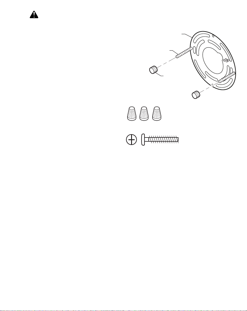
HARDWARE CONTENTS
Note: Illustrations may vary from actual unit.
A
B
C
A - (1x) Mounting Plate
B - (2x) Fixture Mounting
Screws
3x – Wire Connectors
2x – Mounting Plate Screw
C - (2x) Decorative Nut
(This assembly is attached to
the rear of the lantern canopy.)
2 210069-01
Page 3
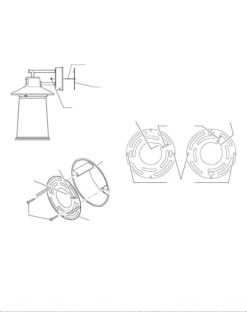
LIGHT FIXTURE INSTALLATION
For best performance, mount the xture about 6 feet (1.8m)
above the ground.
1. Remove two decorative nuts.
2. Remove mounting plate.
3. Tighten mounting screws nger tight.
4. Attach mounting bracket to junction box.
Mounting Screw
Mounting
Plate
Decorative Nut
is xture comes with a universal mounting plate. It is
pre-assembled on the xture to t the majority of junction
box applications.
If the slots on the mounting plate do not line up with the
junction box screw holes, follow these steps:
1. Remove the xture mounting screws from the mounting
plate. Note: Do not remove the ground screw.
2. Attach ground wire “pigtail” to ground screw on
mounting plate (See
Recommended Grounding Method
for additional information).
3. Flip the mounting plate over.
4. Rotate the mounting plate so the wire path is on the
upper right. Note: e wire path on the mounting plate
must be located as shown below to allow the wires on
the back of the xture to pass through.
5. Reinstall the xture mounting screws and attach the
mounting plate to the junction box as shown.
Junction
Box
Mounting Plate
Wire Path
Mounting
Plate Screws
Ground Screw
Note: We recommend having an assistant help hold the
lantern assembly during the wiring process.
Wire Path
Ground Screw
Fixture Screws
As Shipped Flipped and
Rotated
Wire Path
3210069-01
Page 4
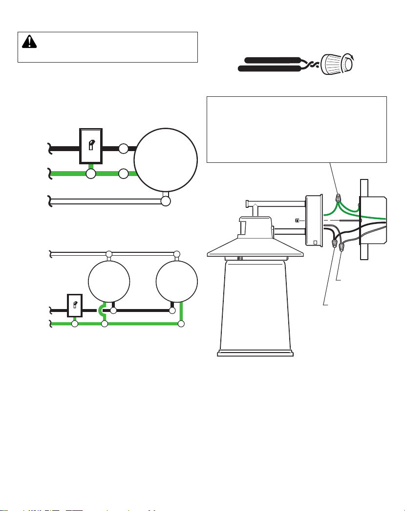
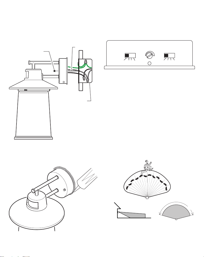
WIRING THE LIGHT FIXTURE
WARNING: Turn power o at circuit breaker
or fuse.
Note: All wiring must be run in accordance with the National Electrical Code through conduit or another acceptable means. Contact a qualied electrician if there is any
question as to the suitability of the system.
Black
Green
or Bare
Copper
White
White
One Motion Light
Light
Fixture
Connect the xture wires to the wires in the junction box.
Twist the wires together and secure with wire connectors.
Recommended Grounding Method
Use a green ground “pigtail” (not provided) and twist
one end together with the bare xture wire and the box
ground wire. Secure with a wire connector. Secure the
other end of the “pigtail” with the GND screw on the
mounting plate.
Black
Green
or Bare
Copper
Light
Fixture
Two Motion Lights
Light
Fixture
White to white
Black to black
If you have metal junction box, you may not need the green
“pigtail”. If you are unsure about the grounding method,
consult your local building code.
4 210069-01
Page 5
MOUNTING THE LIGHT FIXTURE
1. Make sure wire connectors and wires are inside the
junction box.
2. Slide the xture assembly onto the mounting screws.
Tighten decorative nuts removed in step 1 of
Fixture Installation
section securely against xture base.
Light
TESTING AND ADJUSTMENTS
e TEST mode overrides the photocell (daylight shuto
feature) and allows the light xture to be tested day or night
when the DUALBRITE switch is in the T EST position. e
light will stay on for 5 seconds after all motion has stopped.
Decorative Nut
Mounting Screw
Junction
Box
3. Install one medium base light bulb (100 Watt maximum,
tungsten incandescent).
4. Caulk around xture base with silicone weather sealant.
SENS
– +
OFF A B C
Sensor Controls
DUALBRITECHANNEL
OFF TEST 4H D2D
1. Slide the CHANNEL switch to OFF.
2. Slide the DUALBRITE switch to TEST.
3. Set sensitivity control (SENS) to MIN position.
4. Turn on the circuit breaker or fuse and the light switch.
5. Allow the sensor to completely warm up (90 seconds)
before beginning the setup process.
6. Perform a walk test. Walk through the coverage area
noting where you are when the lights turn on.
7.
Stop, wait for the light to turn o (5 seconds), and then
begin walking again. Continue this process until the
detection zone has been established.
8.
Adjust the sensitivity (SENS) to increase or decrease
the range as needed. Too much sensitivity may cause
false triggering due to heat sources in the coverage area
(see
Testing and Adjustments
or
Troubleshooting
section).
Caulking Around Fixture Base
6 ft.
(1.8 m)
30 ft. (9.1 m)
Maximum Range Maximum Coverage Angle
(Top View)
5210069-01
150°
Page 6
LINKING LIGHTS
is light has been designed with Link technology which
allows multiple lights to be connected together wirelessly.
Linked lights can be grouped into one of three possible
channels to create linked zones of lighting. See
nology
section for more information.
Link Tech-
1. Slide the CHANNEL switch to the desired channel
(A, B, or C) on all lights to be linked together.
2. Slide the DUALBRITE switch to the TEST position
on all of the selected lights. Note: e TEST mode
overrides the photocell (daylight shuto feature) and
allows the light xture to be tested day or night.
3. Walk in front of each light to ensure all linked lights
are activated from another linked light. Note: e linked
lights may not come on at the same time because of the
delay of the transmission signal.
FINAL SETUP
1. When testing is complete, set the DUALBRITE switch
to the desired amount of time after dusk the lights should
remain on at a reduced light level [O, 4 Hrs., Dusk-toDawn (D2D)]. See
for more information.
2. e amount of time the lights stay on at full bright after
ALL
motion has stopped in front of
is preset to 5 minutes.
Optional DualBrite® Control
ALL
linked lights
section
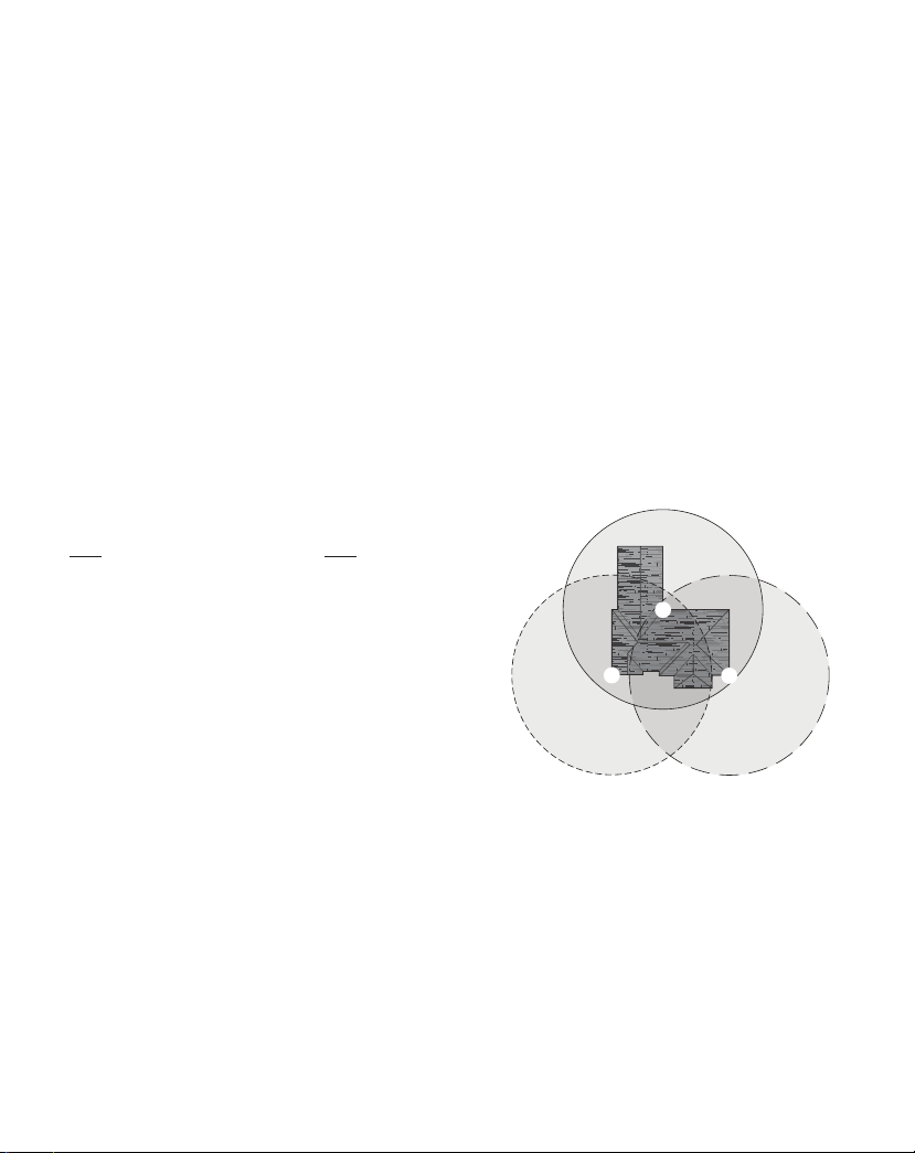
LINK TECHNOLOGY
Link technology allows multiple lights to be connected
together wirelessly. When one light senses motion it will
turn on full bright and send out a wireless signal. All lights
within range and on the same channel will also turn on full
bright. Each time a light receives a signal, it will then repeat
the signal so other lights not in range of the rst light will
also turn on full bright. Linked lights can be grouped into
one of three possible channels (A, B, or C) to create linked
zones of lighting. Note: Linked lights turn o independently
of each other and may not turn o at exactly the same time.
Illustration example:
signal. Light #2 is out of range of light #1 and does not
receive the signal. Light #3 is in range of light #1 and receives
the activation signal. Light #3 is activated and repeats the
signal. Light #2 is in range of light #3 and is activated. Note:
All the lights will send out a signal when activated, even if
the light’s DualBrite switch is set to OFF. If the light is in
manual mode, it will repeat any signal it receives but will
not initiate a signal.
Light #1 senses motion and sends a
3
2
6 210069-01
1
Page 7
OPERATING MODES
Mode: On-Time Works: Day Night
Test
Auto
Accent
Manual
Note: When rst turned on wait about 1 1/2 minutes for
• Motion Sensor (AUTO) – is light xture is designed
• Optional DualBrite® Control – DualBrite mode is
For linked lights, the rst light to sense darkness will
5 Seconds x x
5 Minutes x
O, 4 Hours, Dusk-to-
Dawn
6 Hours or Dawn* x
* resets to Auto Mode at dawn.
the circuitry to calibrate.
to automatically turn on when the sensor detects a temperature dierence moving across the front of the motion
sensor. e amount of time the lights stay on at full bright
after
ALL
motion has stopped in front of
is preset to 5 minutes.
a selectable feature that turns the light on at dusk in a
reduced light level. e light will stay on at the reduced
light level for the amount of time selected [O, 4 hr.,
dusk-to-dawn (D2D)]. When motion is detected, the light
will increase to full bright. e light will stay on at the full
bright level for 5 minutes after
in front of
to the reduced light level. Once the DualBrite timer runs
out, the light will turn ON only when motion is detected
by any of the linked lights. Selecting OFF disables the
DualBrite feature, however the motion sensing and Link
features will continue to work.
turn on all other linked lights on the same channel if the
DualBrite timer has been turned ON on each linked light.
e lights will turn OFF independently of each other and
may not turn OFF at exactly the same time.
ALL
linked lights. e light will then return
ALL
ALL
motion has stopped
x
linked lights
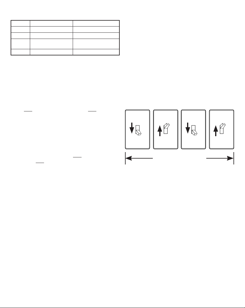
• Manual Mode – Manual mode overrides the motion sensor and “DUALBRITE” control so the light will operate
full bright. is feature only works at night and only for
one night at a time. e motion sensor will reset to motion
sensing mode after 6 hours or sunrise, whichever comes
rst. Manual mode can be toggled on and o using a wall
switch. Note: If the power to the light xture is o for
more than 5 seconds, allow the motion sensor to warm
up prior to switching to manual mode.
1. Ensure the power to the light is ON and the sensor
has warmed up (90 seconds).
2. To turn manual mode on after dark, switch the power
OFF–ON–OFF–ON at the wall switch within 5 seconds.
3. To turn manual mode o, switch the power OFF–ON–
OFF–ON at the wall switch within 5 seconds.
OFF OFFON ON
Less than 5 seconds
IMPORTANT: If manual mode does not turn ON or OFF,
use a slower pace turning the power ON and OFF at the
wall switch while staying within 5 seconds.
CARE AND MAINTENANCE
• To prolong the original appearance, clean with clear water
and a soft damp cloth only.
• Do not use paints, solvents, or other chemicals on this
light xture. ey could cause a premature deterioration
of the nish. is is not a defect in the nish and will not
be covered by the warranty.
• Do not spray with hose or power washer.
7210069-01
Page 8

TROUBLESHOOTING GUIDE
SYMPTOM POSSIBLE CAUSE SOLUTION
Lights will not
come on.
Lights come on in
daylight.
Lights come on for no
apparent reason.
e lights turn o too
late in dusk-to-dawn
(D2D) setting.
Link technology lights
are not activating each
other.
Lights stay on
continuously.
Lights ash on
and o.
Seasonal Temperat ure Changes – e closer the surrounding temperature is to a person’s body heat, the less sensitive the sensor will appear. e greater
the temperature dierence, the more sensitive the sensor will appear. e SENS control might need to be readjusted toward MIN or MAX as the outside
temperature changes for the dierent seasons. is is a normal part of the light sensor’s operation.
1. Light switch is turned o.
2. Light bulb is loose or burned out.
3. Fuse is blown or circuit breaker is turned o.
4. Daylight turn-o is in eect.
5. Sensor not detecting movement.
6. Incorrect circuit wiring, if this is a new installation.
7. e outside air temperature is close to the same as a
person’s body heat.
1. e motion sensor may be installed in a relatively dark
location.
2. e “DUALBRITE” switch is in the “TEST” position.
1. e motion sensor may be sensing small animals or
automobile trac.
2. Sensitivity is set too high.
3. e “DUALBRITE” switch is in the 4 hour or dusk-todawn (D2D) setting.
4. e light xture is linked to another light.
5. e light xture is on the same channel as a neighbor’s
linked light xture.
6. e outside temperature is much warmer or cooler than
a person’s body heat (summer or winter).
7. e light xture is wired through a dimmer or timer.
e light xture may be installed in a relatively dark location. Relocate the light xture or use the 4 hour setting.
1. Linked lights are not set to the same channel.
2. Too many obstructions are creating interference between
the linked lights.
1. e sensor may be picking up a heat source like an air
vent, dryer vent, or br ightly painted, heat-reective surface.
2. e motion sensor is in manual mode.
3. Light control is in DB® mode.
4. Sensitivity is set too high.
5. A linked light xture is picking up continuous motion
and is keeping all linked lights on.
6. Motion is being detected by multiple linked lights and
is keeping all linked lights on.
7. e light xture is wired through a dimmer or timer.
8. e light xture is on the same circuit as a motor,
transformer, or uorescent bulb.
1. Light control is in the TEST mode and warming up.
2. Heat being reected from other objects may be aecting
the sensor.
1. Turn light switch on.
2. Check bulb and replace if burned out.
3. Replace fuse or turn circuit breaker on.
4. Recheck after dark.
5. Increase the “Sensitivity” setting.
6. Verify wiring is correct.
7. Increase the “Sensitivity” setting.
1. e xture is operating normally under these conditions.
2. Set the “DUALBRITE” switch to the OFF, 4 hour, or duskto-dawn (D2D) setting.
1. Reduce sensitivity.
2. Reduce sensitivity.
3. e light xture is operating normally under these circumstances.
4. e light xture is operating normally if linked. e Link option
can be turned OFF or set to a dierent channel.
5. Change the channel of the aected light xtures to a dierent
channel.
6. Reduce sensitivity.
7. Do not use a dimmer or timer to control the light xture. Replace
the dimmer or timer with a standard on/o wall switch.
1. Ensure the linked lights are set to the same channel.
2a. Add a Link light between the existing lights to create an
additional relay point.
2b. Move the Link lights closer to each other.
1. Reduce sensitivity.
2. Switch the motion sensor to auto. S ee
3. Slide DB® switch to OFF position.
4. Reduce sensitivity.
5. e light xtures are operating normally under these circumstances.
6. e light xtures are operating normally under these circumstances.
7. Do not use a dimmer or timer to control the light xture. Replace
the dimmer or timer with a standard on/o wall switch.
8. Install the light xture on a circuit without motors, transformers,
or uorescent bulbs.
1. While in “TEST” mode, the light only stays on for 5 seconds.
Set the “DUALBRITE” switch to OFF, 4 hour, or dusk-todawn (D2D).
2. Reduce sensitivity.
Manual mode
on page 7.
8 210069-01
Page 9

SPECIFICATIONS
Range ................................................................Up to 30 ft. (9.1 m) [varies with surrounding temperature]
Sensing Angle....................................................Up to 150°
Electrical Load .................................................. Up to 100 Watt Maximum Incandescent
Bulb Type ..........................................................Medium Base, Type “A”, 100 Watt Maximum
Power Requirements ..........................................120 VAC, 60 Hz
Operating Modes ..............................................TEST, MOTION ACTIVATED, and MANUAL MODE
ON-Timer .........................................................5 minutes (non-adjustable)
DB® Timer .......................................... O, 4 hours, dusk-to dawn (D2D)
Test Timer .........................................................5 Seconds
Manual Mode Timer .........................................Maximum 6 hours or dawn, whichever comes rst
Link Technology Range .................................... Up to 100 ft (30.5 m) between each Link light xture [varies with sur-
rounding obstructions].
TECHNICAL SERVICE
Please call 1-800-858-8501 (English speaking only) for assistance
before returning product to store.
If you experience a problem, follow this guide. You may also want to visit our Web site at: www.hzsupport.com. If the
problem persists, call* for assistance at 1-800-858-8501 (English speaking only), 8:00 AM to 5:00 PM CST (M-F).
You may also write* to:
HeathCo LLC
P.O. Box 90045
Bowling Green, KY 42102-9045
ATTN: Technical Service
* If contacting Technical Service, please have the following information available: Model Number, Date of Purchase,
and Place of Purchase.
No Service Parts Available for this Product
Please keep your dated sales receipt, it is required for all warranty requests.
9210069-01
Page 10

is is a “Limited Warranty” which gives you specic legal rights. You may also have other rights which vary from state to state
TWO YEAR LIMITED WARRANTY
or province to province.
For a period of 2 years from the date of purchase, any malfunction caused by factory defective parts or workmanship will be, at the
sole option of HeathCo LLC, either repaired or replaced at no charge to you.
Not Covered - Repair service, adjustment and calibration due to misuse, abuse or negligence, light bulbs, batteries, and other
expendable items are not covered by this warranty. Any damage to the light xture resulting from the use of chemicals or a pressure washer machine are not covered by this warranty. Unauthorized service or modication of the product or of any furnished
component will void this warranty in its entirety. is warranty does not include reimbursement for inconvenience, installation,
setup time, loss of use, unauthorized service, or return shipping charges. HeathCo LLC reserves the right to discontinue products
and to change specications at any time without incurring any obligation to incorporate new features in products previously sold.
Finish Warranty Exclusions - Finishes for xtures installed outdoors are subject to change due to prolonged exposure to sunlight,
pollutants, and other environmental conditions. Metal nishes will naturally mature over time, changing in appearance and creating
a living nish. Painted nishes on outdoor xtures may naturally fade over time, depending on the xture’s exposure to the outdoor
elements. us, any claim for fading, discoloration, or “patina” of a nish on an outdoor xture is not applicable to the above warranty. See “Care and Maintenance”, page 7, for proper cleaning of the xture.
is warranty covers only HeathCo LLC assembled products and is not extended to other equipment and components that a
customer uses in conjunction with our products.
THIS WARRANTY IS EXPRESSLY IN LIEU OF ALL OTHER WARRANTIES, EXPRESS OR IMPLIED, INCLUDING
ANY WARRANTY, REPRESENTATION OR CONDITION OF MERCHANT ABILITY OR THAT THE PRODUCTS
ARE FIT FOR ANY PARTICULAR PURPOSE OR USE, AND SPECIFICALLY IN LIEU OF ALL SPECIAL, INDIRECT,
INCIDENTAL, OR CONSEQUENTIAL DAMAGES.
REPAIR OR REPLACEMENT SHALL BE THE SOLE REMEDY OF THE CUSTOMER AND THERE SHALL
BE NO LIABILITY ON THE PART OF HEATHCO LLC FOR ANY SPECIAL, INDIRECT, INCIDENTAL, OR
CONSEQUENTIAL DAMAGES, INCLUDING BUT NOT LIMITED TO ANY LOSS OF BUSINESS OR PROFITS,
WHETHER OR NOT FORESEEABLE. Some states or provinces do not allow the exclusion or limitation of incidental or
consequential damages, so the above limitation or exclusion may not apply to you.
Please keep your dated sales receipt, it is required for all warranty requests.
is device complies with Part 15 of the FCC Rules. Operation is subject to the following two conditions: (1) this device may not cause harmful interference,
and (2) this device must accept any interference received, including interference that may cause undesired operation.
CAN ICES-005 (B)/NMB-005 (B)
Warning: Changes or modications to this unit not expressly approved by the party responsible for compliance could void the user's authority to operate the
equipment.
Note: is equipment has been tested and found to comply with the limits for aClass B digital device, pursuant to part 15 of the FCC Rules. ese limits
are designed to provide reasonable protection againstharmful interferencein a residential installation. is equipment generates, uses and can radiateradio
frequency energyand, if not installed and used in accordance with the instructions, may causeharmful interferenceto radio communications. However, there
is no guarantee that interference will not occur in a particular installation. If this equipment does causeharmful interferenceto radio or television reception,
which can be determined by turning the equipment o and on, the user is encouraged to try to correct the interference by one or more of the following measures:
- Reorient or relocate the receiving antenna.
- Increase the separation between the equipment and receiver.
- Connect the equipment into an outlet on a circuit dierent from that to which the receiver is connected.
- Consult the dealer or an experienced radio/TV technician for help.
is device contains licence-exempt transmitter(s)/receiver(s) that comply with Innovation, Science and Economic Development Canada’s licence-exempt
RSS(s). Operation is subject to the following two conditions:
1. is device may not cause interference.
2. is device must accept any interference, including interference that may cause undesired operation of the device.
FCC Responsible Party Name: HeathCo LLC
Address: 2445 Nashville Road, Bowling Green, KY 42101 U.S.A.
Telephone Number: 800-858-8501
10 210069-01
Page 11

Luz decorativa detectora de
movimiento DualBrite®
Modelo
4034-07
INSTRUCCIONES PARA SU INSTALACIÓN
Y FUNCIONAMIENTO
INFORMACIÓN SOBRE LA SEGURIDAD .....................12
PREPARACIÓN ............................................. 12
FERRETERÍA OFRECIDA .................................... 12
INSTALACIÓN DEL APARATO DE LUZ .......................13
CABLEADO DEL APARATO DE LUZ ......................... 14
MONTAJE DEL APARATO DE LUZ ........................... 15
PRUEBAS Y AJUSTES ....................................... 15
LUCES DE INTERCONEXIÓN ................................16
CONFIGURACIÓN FINAL ...................................16
TECNOLOGÍA LINK .........................................16
MODALIDADES DE OPERACIÓN ........................... 17
CUIDADO Y MANTENIMIENTO ............................. 17
GUÍA DE INVESTIGACIÓN DE AVERÍAS ..................... 18
ESPECIFICACIONES ........................................ 19
SERVICIO TÉCNICO ........................................19
GARANTÍA LIMITADA A 1 AÑO ............................. 20
Luz decorativa detectora de movimiento
¿Preguntas?
Por favor, consulte la guía de solución de
problemas en este manual o llame a nuestro departamento de servicio técnico (solo para Inglés) al
1-800-858-8501, de 8:00 am - 5:00 pm, hora central,
de lunes a viernes antes de volverlo a la tienda.
Guarde este manual para referencia en el futuro.
ADJUNTE SU RECIBO AQUÍ
Se requiere recibo para todas las solicitudes de
garantía.
Para una descripción de la tecnología DualBrite ®, vea la página 17.
© 2019 HeathCo LLC 210069-01 S
Fecha de compra
11210069-01
Page 12

INFORMACIÓN SOBRE LA
SEGURIDAD
Por favor lea y comprenda todo el manual antes de intentar
ensamblar, operar o instalar el producto.
Esta lámpara requiere de 120 voltios CA. Todo el cableado
debe ser de acuerdo con el Código Nacional de Electricidad
(Código Eléctrico Canadiense en Canadá). Algunos códigos
eléctricos locales requieren que la instalación sea hecha por
un electricista calicado.
ADVERTENCIA
• Desconecte la alimentación en el disyuntor o
fusible cuando haga el cableado de la lámpara.
Ponga cinta adhesiva sobre el interruptor del
disyuntor y verique que la electricidad esté
apagada en la lámpara.
PRECAUCIÓN
• No corte ningún cable que tenga conectores
de cables instalados en fábrica ni retire los
conectores.
PREPARACIÓN
Antes de comenzar la instalación, asegúrese de que tiene
todas las piezas. Compare las piezas con la lista de ferretería
ofrecida. Si alguna pieza falta o está dañada, no intente
ensamblar, instalar o utilizar el producto.
Herramientas necesarias para el montaje (no incluidas):
Destornilladores Phillips y de cabeza plana, pinzas, separadores / cortadoras de alambre, multímetro, cinta aislante,
sellador de silicona, gafas de seguridad, guantes de trabajo
y escalera.
• Para una instalación fácil y para operar la luz utilizando
la modalidad Manual, cambie el aparato de luz existente
que funciona con un interruptor de pared.
• No lo conecte a atenuadores o temporizadores.
• Para un mejor funcionamiento, monte la unidad cerca de
6 pies (1,8 m) por encima del suelo.
Tiempo estimado de instalación: 30 minutos
FERRETERÍA OFRECIDA
Nota: Las ilustraciones pueden ser diferentes de la unidad
comprada.
A
B
C
A - (1x) Soporte de montaje
B - (2x) Tornillos de montaje
del aparato
C - (2x) Tuerca decorativa
3x – Conectores de alambre
2x – Tornillo del
soporte de montaje
(Este conjunto está sujeto a
la parte trasera del farol)
12 210069-01
Page 13

INSTALACIÓN DEL APARATO DE LUZ
Para un mejor funcionamiento, instale el aparato a casi
1.8 m del suelo.
1. Quite dos tuercas decorativas.
2. Retire el soporte de montaje.
3. Ajuste lo más que pueda los tornillos para montaje con
sus dedos.
4. Sujete el soporte de montaje a la caja de empalme.
Tornillo de montaje
Soporte de
montaje
Tuerca decorativa
Este aparato viene con una soporte de montaje universal.
Está pre-ensamblado en el aparato para acomodarse a la
mayoría de las aplicaciones de cajas de empalme.
Sin embargo, si las ranuras de la soporte de montaje no se
alinean con los agujeros del tornillo de la caja de empalme:
1. Q uite de la soporte de montaje los tornillos de montaje
del aparato. Nota: No quite el tornillo de a tierra.
2. F ije el cable “exible” al tornillo de a tierra de la soporte
de montaje (Vea
Método recomendado de conexión a tierra
para más información).
3. Voltee la soporte de montaje
4. V
oltee la soporte de montaje de modo que el agujero de
paso del alambre esté en la parte derecha superior. Nota:
El agujero de paso del alambre en la soporte de montaje
debe estar ubicado como se muestra abajo para que los
alambres de la parte de atrás del aparato puedan pasar.
5. Reinstale los tornillos de montaje del aparato y je
la soporte de montaje a la caja de empalme como se
muestra.
La caja de
empalme
Tornillos del tierra
Paso del alambre
Tornillo de
montaje del
soporte
Soporte de
montaje
Nota: Recomendamos tener un asistente que ayude a sostener el conjunto del farol durante el proceso de cableado.
Paso del alambre
Tornillos del tierra
Tornillos del aparato
Como se enviaron Placa volteada
y girada
13210069-01
Paso del alambre
Page 14

CABLEADO DEL APARATO DE LUZ
ADVERTENCIA: Desconecte la alimentación en
el disyuntor o en el fusible.
Nota: Todo el cableado debe realizarse de acuerdo con el
Código Eléctrico Nacional usando tubería o algún otro
medio aceptable. Póngase en contacto con un electricista
calicado si tiene alguna pregunta referente a la aptitud
del sistema.
Negro
Verde o
desnudo
Blanco
Blanco
Luz de un movimiento
Artefacto
de luz
Artefacto
de luz
Artefacto
de luz
Conecte los alambres del aparato a los alambres de la caja
de empalme. Tuerza juntos los alambres y asegúrelos con
conectores de alambre.
Método recomendado de conexión a tierra
Use un “cable exible” verde de tierra (no provisto) y
tuerza un extremo con el cable desnudo del aparato y con
el cable de a tierra de la caja. Asegúrelos con un conector
de cables. Asegure el otro extremo del “cable exible” con
el tornillo de a tierra de la soporte de montaje.
Blanco a
blanco
Negro a negro
Negro
Verde o
desnudo
Luz de dos movimientos
Si tiene una caja de empalme de metal, no necesita el “cable
exible”. Si no está seguro del método de conexión a tierra,
consulte con el código local de construcción.
14 210069-01
Page 15

MONTAJE DEL APARATO DE LUZ
1. Asegúrese que los conectores de alambre y los alambres
estén dentro de la caja de empalme.
2. Deslice el conjunto del aparato sobre los tornillos de
montaje. Apriete las tuercas decorativas quitadas en
el paso 1 de la sección
rmemente en la base del aparato.
Tuerca decorativa
3. Instale una base media para bombilla (100 vatios máximo,
tungsteno incandescente).
4. Calafatee alrededor de la base del aparato con un
sellador de silicona contra la intemperie.
Instalación del Aparato de Luz
Tornillo de montaje
La caja de
empalme
PRUEBAS Y AJUSTES
La modalidad de TEST (PRUEBA) anula la fotocélula
(función de desconexión de la luz del día) y permite probar
la lámpara durante el día o la noche cuando el interruptor
DUALBRITE está en la posición de PRUEBA. La luz
permanecerá encendida por 5 segundos después de que todo
movimiento se haya detenido.
SENS
OFF A B C
– +
Controles del detector
1. Deslice el interruptor CHANNEL a OFF,
2. Deslice el interruptor DUALBRITE a TEST.
3. Fije el control de sensibilidad (SENS) a la posición MIN.
4.
Encienda el disyuntor o fusible y el interruptor de la luz.
5. Deje que el sensor se caliente por completo (90 segundos)
antes de comenzar el proceso de instalación.
6. Haga una prueba de paso. Camine por el área de
cobertura y note dónde está usted cuando las luces se
encienden.
7. Deténgase, espere que la luz se apague (5 segundos), y
luego empiece a caminar de nuevo. Continúe este proceso
hasta que la zona de detección haya sido establecida.
DUALBRITECHANNEL
OFF TEST 4H D2D
Calafateo alrededor de la base del aparato
6 ft.
(1.8 m)
30 ft. (9.1 m)
(
15210069-01
Alcance Máximo
Ángulo dev
Cobertura Máxima
Vista desde arriba
150°
)
Page 16

8.
Regule la sensibilidad (SENS) para aumentar o disminuir el alcance según lo que necesite. Demasiada
sensibilidad puede ocasionar falsas alarmas debido a
fuentes de calor en la zona de cobertura (vea la sección
Ajuste de la zona de cobertura
o la sección
Análisis de averías
LUCES DE INTERCONEXIÓN
Esta luz ha sido diseñada con la tecnología Link que permite
la conexión de múltiples luces entre sí en forma inalámbrica.
Las luces de interconexión se pueden agrupar en uno de tres
posibles canales para crear zonas interconectadas de iluminación. Vea la sección
Tecnología Link
para más información.
1. Deslice el interruptor de CANAL (CHANNEL) al
canal deseado (A, B, o C) en todas las luces que deben
estar interconectadas entre sí.
2. Deslice el interruptor DUALBRITE a la posición de
prueba (TEST) en todas las luces seleccionadas. Nota:
La fase de prueba anula la fotocélula (función de apagado
de la luz del día) y permite que la lámpara sea probada
durante el día o la noche.
3. Camine por delante de cada luz para asegurarse de que
todas las luces interconectadas son activadas desde otra
luz de interconexión. Nota: Las luces interconectadas
pueden no prenderse al mismo tiempo, debido a la
demora de la señal de transmisión.
CONFIGURACIÓN FINAL
1. Cuando termine la prueba, ajuste el interruptor DUALBRITE a la cantidad deseada de tiempo, después del
anochecer, que las luces deben permanecer prendidas a
un nivel reducido [O, 4 Hrs., anochecer al amanecer
(D2D)]. Vea la sección
más información.
2. La cantidad de tiempo que las luces permanecen encendidas a pleno brillo después de que TODO movimiento
se haya detenido frente a TODAS las luces conectadas
está preestablecido a 5 minutos.
Control opcional DualBrite®
para
TECNOLOGÍA LINK
La tecnología Link permite la conexión de múltiples luces
entre sí en forma inalámbrica. Cuando una luz detecta
movimiento se encenderá con todo su resplandor y en-
).
viará una señal inalámbrica. Todas las luces dentro de ese
alcance y en el mismo canal también se encenderán con
todo su resplandor. Cada vez que una luz recibe una señal,
repetirá la señal para que otras luces que no están dentro
del alcance de la primera luz también se encenderán con
todo su resplandor. Las luces de interconexións se pueden
agrupar en uno de tres posibles canales (A, B, o C) para
crear zonas interconectadas de iluminación. Nota: Las luces
interconectadas se apagan independiente la una de la otra
y puede que no se apaguen exactamente al mismo tiempo.
Ejemplo de ilustración:
una señal. La luz # 2 está fuera del alcance de la luz # 1 y no
recibe la señal. La luz # 3 está dentro del alcance de la luz
# 1 y recibe la señal de activación. La luz # 3 se activa y se
repite la señal. La luz # 2 está dentor del alcance de la luz # 3
y se activa. Nota: Todas las luces enviarán una señal cuando
se activan, incluso si el interruptor de la luz DUALBRITE
está en OFF. Si la luz está en fase manual, repetirá cualquier
señal que recibe, pero no la iniciará.
La luz # 1 detecta movimiento y envía
3
2
1
16 210069-01
Page 17

MODALIDADES DE OPERACIÓN
Modalidad: A tiempo: Trabaja:
Prueba
Automático
Adorno
Manual
Nota: Cuando encienda por primera vez, espere 1 1/2 minutos
para que los circuitos se calibren.
• Detector de movimiento (AUTO) – Esta lámpara está
diseñada para prenderse automáticamente cuando el sensor
detecta una diferencia de temperatura que se mueve por
el frente del detector de movimiento. La cantidad de
tiempo que las luces permanecen encendidas a pleno brillo
después de que TODO movimiento se haya detenido
frente a TODAS las luces conectadas está preestablecido
a 5 minutos.
• Control opcional DualBrite® – La fase DUALBRITE
es una característica seleccionable que enciende la luz al
anochecer a un nivel reducido de luz. La luz permanecerá
encendida al nivel reducido de luz por la cantidad de
tiempo seleccionado [O, 4 hr., del anochecer al amanecer
(D2D)]. Cuando se detecte movimiento, la luz brillará
con todo su resplandor. La luz permanecerá encendida al
nivel de brillo completo durante 5 minutos, después de que
TODO
luces interconectadas. La luz volverá entonces al nivel de
luz reducida. Una vez que el temporizador DUALBRITE
se termina, la luz se encenderá sólo cuando el movimiento
es detectado por cualquiera de las luces interconectadas.
Si selecciona OFF desactiva la función DualBrite, sin
embargo, las características de detección de movimiento
y de Link continuarán funcionando.
En cuanto a las luces interconectadas la primera luz
que detecta la oscuridad encenderá todas las otras luces
interconectadas y en el mismo canal si el temporizador
DUALBRITE ha sido prendido (ON) en cada luz
interconectada. Las luces se apagarán independiente la
una de la otra y puede que no se apaguen exactamente al
mismo tiempo.
5 segundos x x
5 minutos x
O, 4 horas, anoche-
cer al amanecer
6 horas o al amanecer*
*Se pone en Automático al amanecer.
movimiento se ha detenido frente a
Día Noche
x
x
TODAS
las
• Modalidad Manual – La modalidad manual anula el sensor de movimiento y el control "DUALBRI TE" para que
la luz funcione a pleno brillo. Esta característica funciona
solamente en la noche y solamente una noche a la vez. El
detector de movimiento se reiniciará en la modalidad de
detección de movimiento después de 6 horas o cuando
salga el sol, lo que ocurra primero. La fase manual puede
también alternar entre encendido y apagado mediante
el interruptor de pared. Nota: Si la energía eléctrica al
aparato de luz es apagada por más de 5 segundos, deje que
el detector de movimiento se caliente antes del cambio a
la fase manual.
1. Asegúrese de que la luz está encendida (ON) y de que
el detector se ha calentado (90 segundos).
2. Para activar la modalidad manual después del anoche-
cer, accione el interruptor de pared según la secuencia
OFF–ON–OFF–ON dentro de 5 segundos.
3. Para desactivar la modalidad manual, APAGUE-
PRENDA- APAGUE- PRENDA la alimentación en
el interruptor de pared en 5 segundos.
APAGADO APAGADO
IMPORTANTE: Si la modalidad manual no se ACTIVA o
DESACTIVA, utilice un ritmo más lento para ACTIVAR
y DESACTIVAR usando el interruptor de pared mientras
lo hace dentro de 5 segundos.
ENCENDIDO ENCENDIDO
Menos de 5 segundos
CUIDADO Y MANTENIMIENTO
• Para prolongar la apariencia original, limpie solo con agua
clara y un paño suave y húmedo.
• No utilice pinturas, disolventes u otros productos químicos
en esta lámpara. Pueden causar un deterioro prematuro
del acabado. Esto no es un defecto en el acabado y no
estará cubierto por la garantía.
• No lo rocíe con una manguera o una lavadora a presión.
17210069-01
Page 18

GUÍA DE INVESTIGACIÓN DE AVERÍAS
SÍNTOMA POSIBLE CAUSA SOLUCIÓN
Las luces no se
prenden.
Las luces se
prenden durante
el día.
Las luces se
prenden sin
ninguna razón
aparente.
Las luces
se apagan
demasiado tarde
en la calibración
crepúsculo-alamanecer (D2D).
Las luces de
tecnología Link
no se activan
entre sí.
Las luces
se quedan
prendidas
continuamente.
1. El interruptor de luz está apagado.
2. La bombilla está oja o quemada.
3. El fusible está quemado o el cortacircuitos está apagado.
4. La modalidad de apagado durante el día está en efecto.
5. El sensor no detecta el movimiento.
6. Alambrado incorrecto, si ésta es una nueva instalación.
7. La temperatura del aire exterior está cercana al calor
corporal de una persona.
1. El detector de movimiento puede estar instalado en un
sitio relativamente oscuro.
2. El interruptor "DUALBRITE" está en la posición
"TEST".
1. El detector de movimiento puede estar detectando
pequeños animales o tráco automotor.
2. La Sensibilidad es demasiado alta.
3. El interruptor “DUALBRITE” está en la calibración 4
horas o del crepúsculo al amanecer (D2D).
4. La lámpara está interconectada con otra luz.
5. La lámpara está en el mismo canal que el aparato
enlazado del vecino.
6. La temperatura exterior está más caliente o más fría que
el calor corporal de una persona (verano o invierno).
7. El aparato de luz está cableado a través de un reductor
de luz o de un temporizador.
El aparato de luz puede estar instalado en un sitio
relativamente oscuro.
1. Las luces vinculadas no están conguradas en el mismo
canal.
2. Demasiadas obstrucciones están creando interferencia
entre las luces conectadas.
1. El sensor puede detectar fuentes de calor, como ductos
de calefacción y de aire acondicionado, o supercies
resplandecientes que reejan la luz.
2. El detector de movimiento está en la fase manual.
3.
El control de luz está en la modalidad DB®.
4. La Sensibilidad es demasiado alta.
5. Una lámpara interconectada está captando movimiento
continuo y está manteniendo prendidas todas las luces
interconectadas.
6. Múltiples luces interconectadas detectan movimiento
lo que mantiene encendidas a todas las luces
interconectadas.
7. El aparato de luz está cableado a través de un reductor
de luz o de un temporizador.
8. El aparato de luz está en el mismo circuito que un
motor, transformador o tubo uorescente.
1. Encienda el interruptor de luz.
2. Revise la lámpara y cámbiela si está quemada.
3. Cambie el fusible encienda el disyuntor.
4. Revíselo después del anochecer.
5. Aumente el ajuste de sensibilidad (“SENS”).
6. Verique que el cableado esté correcto.
7. Aumente el ajuste de sensibilidad (“SENS”).
1. El aparato está funcionando normalmente bajo estas condiciones.
2. Fije el interruptor "DUALBRITE" a la posición OFF, 4 horas, o
la conguración del anochecer hasta el amanecer (D2D).
1. Reduzca la sensibilidad.
2. Reduzca la sensibilidad.
3. El aparato de luz está operando normalmente bajo estas
circunstancias.
4. La opción Link puede ser apagada (OFF) o jada a un canal
diferente.
5. Cambie el canal de las lámparas afectadas a un canal diferente.
6. Reduzca la sensibilidad.
7. No use un reductor de luz o un temporizador para controlar el
aparato de luz. Cambie el reductor de luz o el temporizador por
un interruptor de pared estándar de encendido/apagado.
Cambie la ubicación de la lámpara o utilice la conguración de 4
horas.
1. Asegúrese de que las luces vinculadas estén conguradas en el
mismo canal.
2a. Agregue una luz Link entre las luces existentes para crear un
punto de relé adicional.
2b. Mueva las luces Link más cerca la una de la otra.
1. Reduzca la sensibilidad.
2. Cambie el detector de movimiento a automático. Vea
manual
3. Deslice el interruptor DB® a la posición de apagado (o).
4. Reduzca la sensibilidad.
5. Las lámparas están funcionando normalmente bajo estas
circunstancias.
6. Las lámparas están funcionando normalmente bajo estas
circunstancias.
7. No use un reductor de luz o un temporizador para controlar el
aparato de luz. Cambie el reductor de luz o el temporizador por
un interruptor de pared estándar de encendido/apagado.
8. Instale el aparato de luz en un circuito sin motores,
transformadores o tubos uorescentes.
en la página 17.
Modadlidad
18 210069-01
Page 19

GUÍA DE INVESTIGACIÓN DE AVERÍAS
La luce se
prenden y se
apagan.
Cambios estacionales de temperatura - Cuanto más cerca esté la temperatura ambiental al calor del cuerpo de una persona, el detector parecerá menos
sensible. Cuanto mayor sea la diferencia de temperatura, el detector parecerá más sensible. El control SENS puede necesitar ser recalibrado hacia MIN o
MAX a medida que la temperatura exterior cambia debido a las diferentes estaciones del año. Esta es una parte normal del funcionamiento del detector de luz.
1. El control de luz está en fase de Prueba y calentándose.
2. El calor que se reeja de otros objetos pueden estar
afectando al detector.
1. Mientras está en la fase PRUEBA, la luz sólo queda encendida
por 5 segundos. Fije el interruptor "DUALBRITE" en OFF, 4
horas, o del anochecer hasta el amanecer (D2D).
2. Reduzca la sensibilidad.
Alcance .................................................................. Hasta 9.1 m. (varía con la temperatura del medio ambiente).
Ángulo de detección .............................................. Hasta 150°
Carga Eléctrica ...................................................... Hasta un máximo de 100 vatios de incandescente
Tipo de bombilla ................................................... Casquillo mediano, tipo “A” de 100 vatios máximo
Requisitos de Energía ............................................ 120 VCA, 60 Hz
Fases de Operación ................................................PRUEBA, ACTIVADO POR MOVIMIENTO y FASE MANUAL
Temporizador de duración (del encendido) ........... 5 minutos (No regulable)
Temporizador de DB® ............................. Apagado, 4 horas, del atardecer al amanecer (D2D)
Temporizador de prueba ........................................ 5 segundos
Temporizador de la fase manual ............................ Máximo de 6 horas o hasta el amanecer, lo que ocurra primero
Alcance de la tecnología de interconexión ............. Hasta 100 pies (30,5 m) entre cada accesorio de luz Link [varía de
acuerdo a las obstrucciones circundantes].
SERVICIO TÉCNICO
Favor de llamar al 1-800-858-8501 (sólo para hablar en inglés) para pedir ayuda antes de
devolver el producto a la tienda.
Si tiene algún problema, siga esta guía. Usted puede también visitar nuestro sitio Web: www.hzsupport.com. Si el
problema continúa, llame al 1-800-858-8501 (sólo para hablar en inglés), de 8:00 AM a 5:00 PM CST (L-V). Usted
puede también escribir a:
HeathCo LLC
P.O. Box 90045
Bowling Green, KY 42102-9045
ATTN: Technical Service (Servicio Técnico)
* Si se llama al Servicio Técnico, por favor tener lista la siguiente información: Número de Modelo, Fecha de compra y
Lugar de compra.
No hay piezas de servicio disponibles para este producto.
Por favor guarde su recibo de venta fechado; se lo requiere para cualquier solicitud de garantía.
ESPECIFICACIONES
19210069-01
Page 20

Esta es una “Garantía Limitada” que le da a Ud. derechos legales especícos. Usted puede también tener otros derechos que varían
GARANTÍA LIMITADA A 2 AÑOS
de estado a estado o de provincia a provincia.
Por un período de 2 años a partir de la fecha de compra, cualquier mal funcionamiento causado por piezas defectuosas o por mano
de obra será reparado o reemplazado sin cargo alguno, a criterio exclusivo de HeathCo LLC.
No cubierto - Servicio de reparación, ajuste y calibración debido al mal uso, abuso o negligencia, bombillas, baterías, u otras partes
fungibles no están cubiertas por esta garantía. Cualquier daño en el aparato de luz como resultado de usar productos químicos o
lavadora a presión no están cubiertos por esta garantía. Los Servicios no autorizados o modicaciones del producto o de cualquier
componente que se provee invalidarán esta garantía en su totalidad. Esta garantía no incluye reembolso por inconveniencia, instalación, tiempo de instalación, perdida de uso, servicio no autorizado, o costos de transporte de retorno. HeathCo LLC se reserva el
derecho de descontinuar productos y de cambiar especicaciones a cualquier momento sin incurrir en ninguna obligación de tener
que incorporar nuevas características en los productos vendidos con anterioridad.
Exclusiones de garantía de los acabados – Los acabados de los aparatos instalados al aire libre están sujetos a cambios debido a su
exposición prolongada a la luz solar, a los contaminantes y a otras condiciones ambientales. Los acabados de metal, naturalmente,
madurarán con el tiempo, cambiando su apariencia y creando un acabado patinado. Los acabados pintados en aparatos al aire libre
pueden desteñirse en forma natural con el tiempo, dependiendo de la exposición del aparato a la intemperie. Por lo tanto, cualquier
reclamo por desteñido, decoloración o "pátina" del acabado de un accesorio al aire libre no es aplicable a la garantía antes mencionada.
Vea la sección "Cuidado y mantenimiento" en la página 17, para una limpieza adecuada del aparato.
Esta garantía cubre solamente los productos ensamblados por HeathCo LLC y no se extiende a otros equipos o componentes que
el consumidor usa junto con nuestros productos.
ESTA GARANTÍA ESTÁ EXPRESAMENTE EN LUGAR DE OTRAS GARANTÍAS, EXPRESADAS O SOBREENTENDIDAS, INCLUYENDO CUALQUIER GARANTÍA, REPRESENTACIÓN O CONDICIÓN DE COMERCIABILIDAD O QUE LOS PRODUCTOS SE ADAPTEN PARA CUALQUIER PROPÓSITO O USO EN PARTICULAR,
Y ESPECIFICAMENTE EN LUGAR DE TODOS LOS DAÑOS ESPECIALES, INDIRECTOS, INCIDENTALES Y
CONSECUENTES.
LA REPARACIÓN O EL REEMPLAZO DEBERÍA SER LA ÚNICA SOLUCIÓN DEL CLIENTE Y NO HABRÁ
RESPONSABILIDAD POR PARTE DE HEATHCO LLC POR CUALQUIER DAÑO ESPECIAL, INDIRECTO, INCIDENTAL O CONSECUENTE, INCLUIDOS PERO NO LIMITADOS A CUALQUIER PÉRDIDA DE NEGOCIO
O GANACIAS SEAN O NO PREVISIBLES. Algunos estados o provincias no permiten la exclusión o limitación de daños
incidentales o consecuentes, de modo que la limitación o exclusión arriba indicada puede que no se aplique a Ud.
Por favor guarde su recibo de venta fechado; se lo requiere para cualquier solicitud de garantía.
Este aparato cumple con la Parte 15 de las Reglas de la FCC. La operación está sujeta a las dos siguientes condiciones: (1) este aparato no puede causar interferencias perjudiciales y (2) este aparato debe aceptar cualquier interferencia recibida, incluyendo una interferencia que pueda causar un funcionamiento indeseado.
CAN ICES-005 (B)/NMB-005 (B)
Advertencia: los cambios o modicaciones hechas a esta unidad que no estén expresamente aprobados por la parte responsable del cumplimiento pueden anular
la autoridad del usuario para operar el equipo.
Nota: Este equipo ha sido probado y se lo encontró que cumple con los límites para un dispositivo digital de Clase B, de acuerdo con la parte 15 de las Normas
de la FCC. Estos límites están diseñados para proporcionar una protección razonable contra interferencias dañinas en una instalación residencial. Este equipo
genera, usa y puede irradiar energía de radiofrecuencia y, si no se lo instala y usa de acuerdo con las instrucciones, puede causar interferencia dañina a las comunicaciones de radio. Sin embargo, no hay garantía de que la interferencia no ocurra en una instalación en particular. Si este equipo causa interferencia dañina a
la recepción de radio o televisión, lo que se puede determinar apagando y encendiendo el equipo, se recomienda que el usuario intente corregir la interferencia
mediante una o más de las siguientes medidas:
- Reoriente o reubique la antena receptora.
- Aumente la separación entre el equipo y el receptor.
- Conecte el equipo a un tomacorriente en un circuito diferente al que está conectado el receptor.
- Para recibir ayuda consulte con el distribuidor o con un técnico experto en radio / TV.
Este dispositivo contiene transmisores / receptores exentos de licencia que cumplen con los RSS exentos de licencia de Canadá de Innovación, Ciencia y Desarrollo
Económico. Su funcionamiento está sujeto a las dos siguientes condiciones:
1. Este dispositivo no puede causar interferencia.
2. Este dispositivo debe aceptar cualquier interferencia, incluyendo la interferencia que pueda causar un funcionamiento indeseado del dispositivo.
Nombre de la parte responsable de la CFC: HeathCo LLC
Dirección: 2445 Nashville Road, Bowling Green, KY 42101 U.S.A.
Número de teléfono: 800-858-8501
20 210069-01
Page 21

Luminaire décoratif à
détecteur de mouvement
et fonction DualBrite
INSTRUCTIONS D’INSTALLATION ET
MODE D’EMPLOI
RENSEIGNEMENTS DE SÉCURITÉ ...........................22
PRÉPARATION .............................................22
QUINCAILLERIE FOURNIE .................................. 22
INSTALLATION DU LUMINAIRE ............................. 23
BRANCHEMENT DU LUMINAIRE ............................24
MONTAGE DU LUMINAIRE .................................25
ESSAIS ET RÉGLAGES ...................................... 25
INTERCONNEXION DES LUMINAIRES .......................26
RÉGLAGE FINAL ........................................... 26
TECHNOLOGIE LINK ....................................... 26
MODES DE FONCTIONNEMENT ............................ 27
ENTRETIEN ET MAINTENANCE ............................. 27
GUIDE DE DÉPANNAGE .................................... 28
FICHE TECHNIQUE ......................................... 29
SERVICE TECHNIQUE ......................................29
GARANTIE LIMITÉE DE 1 AN ................................30
MD
Modèle
4034-07
Luminaire décoratif à détecteur de mouvement
Consultez le guide de dépannage du guide ou
communiquez avec le service technique (en anglais
seulement) au 1800858-8501, de 8 h à 17 h, HNC,
du lundi au vendredi avant de retourner chez le
détaillant.
Des questions?
Conservez ce guide à titre de référence.
FIXEZ VOTRE REÇU DE CAISSE ICI
Le reçu est nécessaire pour toute demande sous
garantie.
Pour une description de la technologie DualBriteMD, consultez
la page 27.
© 2019 HeathCo LLC 210069-01 F
Date d’achat
21210069-01
Page 22

RENSEIGNEMENTS DE SÉCURITÉ
Veuillez lire et bien comprendre le guide avant de tenter
d’assembler, d’utiliser ou d’installer le produit.
Ce luminaire exige une alimentation de 120 volts c.a. Tout
le câblage doit être conforme au National Electrical Code
(Code canadien de l’électricité au Canada). Certains codes
électriques locaux exigent qu’un électricien accrédité installe
ce luminaire.
AVERTISSEMENT
• Coupez l’alimentation au niveau du disjoncteur
ou du fusible pour brancher le luminaire. Placez
un bout de ruban adhésif sur le disjoncteur
assurez-vous que le courant est bien coupé au
luminaire.
ATTENTION
• Ne coupez aucun l doté de capuchons de
connexion installés en usine et ne retirez pas ces
capuchons de connexion.
PRÉPARATION
Avant de commencer l’installation du produit, assure z-vous
de bien avoir toutes les pièces. Comparez les pièces avec la
liste de la quincaillerie fournie. S’il manque une pièce ou
si l’une d’elles est endommagée, ne tentez pas d’assembler
d’installer ou d’utiliser le produit.
Outils nécessaires à l’assemblage (non fournis):Tournevis
Phillips et à lame droite, pinces, pinces à dénuder et à couper,
multimètre, ruban adhésif électrique, scellant d’étanchéité
à la silicone, lunettes de sécurité, gants de travail et échelle.
• Pour une installation et une utilisation faciles au moyen du
mode Manuel, remplacez un luminaire existant commandé
par interrupteur mural.
• Ne connectez pas ce luminaire à un gradateur ni à une
minuterie.
• Pour un meilleur rendement, installez le luminaire à
environ 6 pieds (1,8 m) du sol.
Durée estimative de l’installation:30 minutes
QUINCAILLERIE FOURNIE
Remarque :Les illustrations peuvent être diérentes de
l’appareil acheté.
A
B
C
A - (1x) Support de montage
B - (2x) Vis de montage du
luminaire
C - (2x) Écrou décoratif
3x – Capuchons de
connexion
2x – Vis de montage
du support
Support de
montage
(Cet élément est xé
à l’endos du couvercle de
la lanterne.)
Boîte de
jonction
Vis de
montage du
support
22 210069-01
Vis de mise
à la terre
Page 23

INSTALLATION DU LUMINAIRE
Pour un rendement optimal, montez le luminaire à environ
1,8 m au-dessus du sol.
1. Retirez les deux écrous décoratifs.
2. Retirez le support de montage.
3. Serrez à la main les vis de la croix.
4. Fixez le support de montage à la boîte de jonction.
Vis de montage
Support de
montage
Écrou décoratif
Ce luminaire vous est fourni avec un support universel; déjà
xé au luminaire, ce suppor t convient à la majorité des boîtes
de raccordement électrique.
Toutefois, si les rainures de la support de montage ne correspondent pas aux trous des vis de la boîte :
1. Retirez les vis de xation au luminaire de la support de
montage. Remarque : Ne retirez pas la vis de mise à la
terre.
2. Fixez la « rallonge » du l de terre à la vise de mise à
la terre de la support de montage (consultez la section
Méthode de mise à la terre recommandée
pour plus de détails).
3. Retournez la support de montage.
4. Faites tourner la support de montage de sorte que l’or ice
de passage des ls se trouve dans le coin supérieur droit.
Remarque : L’orice de passage des ls de la support de
montage doit être placé comme illustré ci-dessous pour
permettre le passage des ls à l’arrière du luminaire.
5. Remettez en place les vis de xation au luminaire et la
vis de mise à la terre, puis xez la support de montage
à la boîte de raccordement, comme illustré.
Boîte de
jonction
Vis de mise à la terre
Passage des ls
Vis de
montage du
support
Support de montage
Remarque : Il est recommandé de demander à une autre
personne de tenir la lanterne pendant le passage des ls.
Passage
des ls
Vis de mise à la
terre
Vis de xation au
luminaire
Tel qu’expédié Plaque retournée,
après rotation
23210069-01
Passage
des ls
Page 24

BRANCHEMENT DU LUMINAIRE
MISE EN GARDE : Coupez l’alimentation au
disjoncteur ou au fusible.
Remarque : Le câblage doit être conforme aux exigences
du Code national de l’électricité et être installé dans des
canalisations ou autres dispositifs acceptables. Si vous
avez des doutes concernant la convenance du système,
consultez un électricien reconnu.
Noir
Vert ou
dénudé
Blanc
Blanc
Une lanterne à détecteur de mouvement
Luminaire
Branchez les ls du luminaire aux ls dans la boîte de
raccordement. Torsadez ces ls ensemble, puis ajoutez-y
un connecteur de ls.
Méthode de mise à la terre recommandée
Utilisez une «queue de cochon» verte (non fournie) et
torsadez-en une extrémité avec le l nu du luminaire et
le l de terre de la boîte de jonction. Utilisez un serre-ls.
Fixez l’autre extrémité de la «queue de cochon» avec la
vis de terre (GND) sur la support de montage.
blanc/blanc
Luminaire Luminaire
Noir
Vert ou
dénudé
Deux lanternes à détecteur de mouvement
noir/noir
Si la boîte de jonction est en métal, vous pourriez nécessiter
une «queue de cochon» verte. Si vous avez des doutes sur la
méthode de mise à la terre, consultez votre code du bâtiment.
24 210069-01
Page 25

1. Assurez-vous que les capuchons de connexion et les ls
MONTAGE DU LUMINAIRE
sont bien insérés dans la boîte de jonction.
2. Faites glisser le socle du luminaire sur les vis de montage.
Serrez solidement les écrous décoratifs retirés à l’étape
1 de la section
du luminaire base.
Écrou décoratif
3. Installez une ampoule à culot moyen (maximum de
100W, tungstène à incandescence).
4. Calfeutrez autour de la base du luminaire avec du
mastic silicone résistant aux intempéries.
Installation du luminaire
contre la base
Vis de montage
Boîte de
jonction
ESSAIS ET RÉGLAGES
Le mode TEST contourne le fonctionnement de la photocellule (qui coupe l’éclairage le jour) et permet de faire l’essai
du luminaire de jour comme de nuit lorsque le commutateur
DUALBRITE est en position TEST. L’éclairage demeure
allumé pendant cinq secondes après que le mouvement
s’est arrêté.
SENS
OFF A B C
– +
Commandes du détecteur
1. Faites glisser le commutateur CHANNEL en position
OFF.
2. Placez le commutateur DUALBRITE en postillon
TES T.
3. Réglez la commande de sensibilité (SENS) à la position
MIN.
4. Réenclenchez le disjoncteur ou le fusible et placez
l’interrupteur à ON.
5. Laissez le détecteur se réchauer complètement (90
secondes) avant de commencer le réglage.
6. Eectuez un test de passage.
de couverture, en remarquant l’endroit où vous trouvez
lorsque la lumière s’allume.
7.
Arrêtez-vous, attendez que la lumière s’éteigne (5
secondes), puis recommencez à marcher. Continuez
ainsi jusqu’à ce que vous ayez établi la zone de détection.
DUALBRITECHANNEL
OFF TEST 4H D2D
Déplacez-vous dans la zone
Scellant d’étanchéité autour de la base
6 ft.
(1.8 m)
30 ft. (9.1 m)
Portée maximale Angle de
couverture maximale
(Vue en plongée)
25210069-01
150°
Page 26

8. Régler la sensibilité (SENS) selon les besoins. Une trop
grande sensibilité pourrait entraîner des déclenchements
intempestifs attribuables à des sources de chaleur dans
la zone de couverture (consultez les sections
réglages
ou
Guide de dépannage
).
Essais et
INTERCONNEXION DES LUMINAIRES
Ce luminaire intègre la technologie Link qui permet d’interconnecter sans l de multiples luminaires. Les luminaires
peuvent être interconnectés par le biais d’une à trois voies
pour créer des zones d’éclairage interconnectées. Consultez
la section
Technologie Link
pour plus de détails.
1. Faites glisser le commutateur CHANNEL sur la voie
souhaitée (A, B ou C) sur tous les luminaires à interconnecter.
2. Faites glisser le commutateur DUALBRITE en
position TEST sur tous les luminaires sélectionnés.
Remarque:Le mode TEST contourne la photocellule
(qui ferme le luminaire pendant la journée), permettant
de faire l’essai du luminaire de jour comme de nuit.
3. Marchez devant chaque luminaire pour vous assurer
que tous les luminaires interconnectés sont déclenchés
par un des autres luminaires du groupe. Remarque:Les
luminaires pourraient ne pas tous s’allumer simultanément en raison du délai de transmission du signal.
RÉGLAGE FINAL
1. Une fois l’essai terminé, faites glisser le commutateur
DualBrite jusqu’à la valeur désirée de fonctionnement
du luminaire à faible intensité une fois la nuit tombée
[Arrêt (O), 4 hres, Du coucher au lever (Dusk-toDawn - D2D)]. Consultez la section sur la
DualBriteMD facultative
pour plus de détails.
2. Le délai pendant lequel les luminaires demeurent allumés
à pleine puissance après qu’AUCUN mouvement n’est
détecté par TOUS les luminaires reliés est préréglé à 5
minutes.
Commande
TECHNOLOGIE LINK
La technologie Link permet l’interconnexion sans l de
multiples luminaires. Lorsque l’un des luminaires détecte un
mouvement, il s’allume à pleine intensité et envoie un signal
sans l. Tous les luminaires à portée et interconnectés à la
même voie s’allument alors aussi à pleine intensité. Chaque
fois qu’un luminaire reçoit un signal, il le renvoie de sorte que
les autres luminaires à portée du premier luminaire s’allument
aussi à pleine intensité. Les luminaires peuvent être interconnectés par le biais d’une à trois voies (A, B ou C) pour
créer des zones d’éclairage interconnectées. Remarque:Les
luminaires interconnectés se ferment indépendamment les
uns des autres, de sorte qu’il se pourrait qu’ils ne s’éteignent
pas tous simultanément.
Exemple illustré:
et envoie un signal. Le luminaire n°2 est hors de la portée du luminaire n°1 et ne reçoit donc pas le signal. Le
luminaire n° 3 est à portée du luminaire n° 1 et reçoit
donc le signal. Le luminaire n°3 s’allume, puis renvoie
le signal. Le luminaire n°2, qui est à portée du luminaire
n°3, s’allume. Remarque:Tous les luminaires émettent un
signal au moment où ils s’allument, même si le commutateur
DualBrite est en position OFF. Lorsque le luminaire est en
mode manuel, il répète tous les signaux reçus, mais n’émet
pas le premier signal.
Le luminaire n°1 détecte un mouvement
3
2
1
26 210069-01
Page 27

MODES DE FONCTIONNEMENT
Mode: Temps en circuit:
Essai
Auto
Accentuation
Manuel
5 secondes x x
5 minutes x
Arrêt, 4 heures, Du
coucher au lever
6 heures ou à l’aube*
* Revient au mode automatique au lever du soleil.
Remarque : Après mise en circuit, attendre enron 1 1/2
minute pour que l’étalonnage du circuit soit complété.
•
Détecteur de mouvement (AUTO) –
conçu pour s’allumer automatiquement lorsque le détecteur
décèle une diérence de température qui se déplace devant
lui dans la zone de couverture.
luminaires demeurent allumés à pleine puissance après
qu’AUCUN mouvement n’est détecté par TOUS les
luminaires reliés est préréglé à 5 minutes.
• Commande DualBriteMD facultative – Le mode Dual-
Brite est une fonction réglable du luminaire qui permet
d’allumer l’éclairage à intensité réduite à la brunante. Le
luminaire demeure allumé à intensité réduite pendant la
durée sélectionnée [Arrêt (O), 4 hres, Du coucher au
lever (Dusk-to-Dawn - D2D)]. Lorsqu’un mouvement
est détecté, l’éclairage s’allume à pleine intensité. Le
luminaire demeure allumé à pleine intensité pendant
5 minutes après que
TOUS
les luminaires interconnectés. L’éclairage repasse
TOUT
mouvement a cessé devant
ensuite à intensité réduite. Une fois le délai de la minuterie DualBrite écoulé, l’éclairage s’allume uniquement
lorsqu’un mouvement est détecté par l’un des luminaires
interconnectés. La sélection de OFF désactive la fonction
DualBrite, mais les fonctions de détection de mouvement
et deLinkcontinueront à fonctionner.
Pour ce qui est des luminaires interconnectés, le premier
luminaire qui décèle la noirceur allume tous les luminaires
interconnectés à la même voie lorsque la commande de
la minuterie DualBrite de ces luminaires est en position
ON. Les luminaires interconnectés se ferment indépendamment les uns des autres, de sorte qu’il se pourrait qu’ils
ne s’éteignent pas tous simultanément.
En fonction:
jour nuit
x
x
Ce luminaire est
Le délai pendant lequel les
• Mode Manuel – Le mode MANUAL contourne le fonctionnement du détecteur de mouvement et la commande
DUALBRITE de sorte que le luminaire fonctionne à
pleine puissance. Cette caractéristique fonctionne seulement à nuit, et une seule nuit à la fois. Le détecteur de
mouvement repasse en mode détection après six heures
ou au moment du lever du soleil, selon la première éventualité. Le mode manuel peut aussi être activé et désactivé
au moyen d’un interrupteur mural. REMARQUE: Lorsque
l’alimentation du luminaire est coupée pendant plus de cinq
secondes, laissez le détecteur de mouvement se réchauer
avant de passer au mode manuel.
1. Assurez-vous que le luminaire est bien SOUS TEN-
SION et que le détecteur a eu le temps de se réchauer
(90 secondes).
2. Pour activer le mode Manual à la nuit tombée, actionner
l’interrupteur mural selon la séquence « ARRÊTMARCHE-ARRÊT-MARCHE » en moins de 5
secondes.
3. Pour désactiver le mode manuel, exécutez la séquence
HORS TENSION-SOUS TENSION-HORS TENSION-SOUS TENSION en moins de 5 secondes à
l’interrupteur mural.
HORS
TENSION
SOUS
TENSION
HORS
TENSION
SOUS
TENSION
Moins de 5 secondes
IMPORTANT : Si le mode Manuel n’est pas automatiquement
ACTIVÉ ou DÉSACTIVÉ, essayez de réduire la fréquence
de MISE SOUS/HORS TENSION de l’appareil au moyen
de l’interrupteur mural, tout en actionnant toutefois ce
dernier en moins de 5 secondes.
ENTRETIEN ET MAINTENANCE
• Pour conserver l’apparence originale du luminaire, nettoyezle uniquement au moyen d’eau douce et d’un chion mouillé.
• N’appliquez aucune peinture, solvant ou produit chimique
sur ce luminaire. Cela pourrait entraîner une détérioration
prématurée du ni. Il ne s’agit pas d’un défaut du ni et
ce ne sera pas couvert dans le cadre de la garantie.
• Évitez d’asperger au moyen d’un boyau ou d’un nettoyeur
à pression.
27210069-01
Page 28

GUIDE DE DÉPANNAGE
SYMPTÔME CAUSE POSSIBLE SOLUTION
L’éclairage ne
s’allume pas.
L’éclairage
s’allume en plein
jour.
L’éclairage
s’allume sans
raison apparente.
L’éclairage
s’éteint trop tard
lorsqu’il est réglé
à DUSK TO
DAWN (D2D).
Les luminaires
dotés de la
technologie
Link ne
s’activent pas les
uns les autres.
L’éclairage
demeure allumé
continuellement.
1. L’interrupteur d’éclairage est hors tension.
2. L’ampoule est lâche ou grillée.
3. Le fusible a sauté ou le disjoncteur a été déclenché.
4. La fonction de fermeture pendant le jour est activée.
5. Capteur, sans détection de mouvement.
6. Mauvais câblage du circuit, dans le cas d’une
nouvelle installation.
7. La température de l’air extérieur est proche de la
température corporelle d’une personne.
1. Le détecteur de mouvement est installé dans un
endroit relativement sombre.
2. Le commutateur DUALBRITE est en position
TES T.
1. Le capteur détecte de petits animaux ou la
circulation automobile.
2. Le réglage de sensibilité est trop élevé.
3. Le commutateur « DUALBRITE» est en position
3, 6 ou DUSK TO DAWN (D2D).
4. Le luminaire est interconnecté avec un autre
luminaire.
5. Le luminaire est sur la même voie que celle d’un
luminaire interconnecté d’un voisin.
6.
La température extérieure est de loin supérieure ou
inférieure à la température corporelle d’une personne
(été ou hiver).
7. Le luminaire est branché à un gradateur ou à une
minuterie.
Le luminaire est installé dans un endroit relativement
sombre.
1. Les luminaires reliés ne sont pas congurés sur le
même canal.
2. De nombreux obstacles créent de l’interférence
entre les luminaires reliés.
1. Le capteur peut percevoir une source de chaleur
comme une sortie d’air, un évent de sécheuse ou une
surface de couleur claire rééchissant la chaleur.
2. Le détecteur de mouvement est en mode manuel.
3. Un des luminaires interconnectés détecte continuellement un mouvement et garde allumés tous les
luminaires interconnectés.
4. De multiples luminaires détectent un mouvement et
gardent tous les luminaires interconnectés allumés.
5. La commande d’éclairage est en mode
DBMD.
6. Le réglage de portée est trop élevé.
7. Le luminaire est branché à un gradateur ou à une
minuterie.
8. Le luminaire est branché au même circuit qu’un
moteur, un transformateur ou un uorescent.
1. Mettre l’interrupteur sous tension.
2. Vérier l’ampoule et la remplacer si elle est grillée.
3. Remplacer le fusible ou ré-enclencher le disjoncteur.
4. Essayer de nouveau après la tombée de la nuit.
5. Augmenter le réglage de la sensibilité.
6. S’assurer que le câblage est approprié.
7. Augmenter le réglage de la sensibilité.
1. Le luminaire fonctionne normalement dans de telles conditions.
2. Réglez le commutateur DUALBRITE en position Arrêt (O), 4 hres,
Du coucher au lever (Dusk-to-Dawn - D2D).
1. Réduisez la portée.
2. Réduisez la sensibilité.
3. Le luminaire fonctionne normalement dans ces circonstances.
4.
Le luminaire fonctionne normalement lorsqu’il est interconnecté. L’option
Link peut être désactivée (OFF) ou congurée pour une autre voie.
5. Faites passer à voie des luminaires touchés à une autre voie.
6. Réduisez la sensibilité.
7. N’utilisez pas de gradateur ni de minuterie pour commander
l’éclairage. Remplacez le gradateur ou la minuterie par un interrupteur
mural standard.
Déplacez le luminaire ou utilisez le réglage 4 heures (4 hour).
1. Assurez-vous que les luminaires reliés sont congurés sur le même
canal.
2a. Ajouter un luminaire Link entre les luminaires en place pour créer un
point de relais supplémentaire.
2b. Rapprochez les luminaires Link les uns des autres.
1. Réduisez la portée.
2. Placez le détecteur de mouvement en mode AUTO. Consultez la
section
3. Les luminaires fonctionnent normalement dans de telles situations.
4. Les luminaires fonctionnent normalement dans de telles situations.
5. Faire glisser le commutateur DBMD en position OFF.
6. Réduisez la sensibilité.
7. N’utilisez pas de gradateur ni de minuterie pour commander
l’éclairage. Remplacez le gradateur ou la minuterie par un interrupteur
mural standard.
8. Branchez le luminaire à un circuit ne comportant pas de moteur, de
transformateur ni de uorescent.
Mode manuel
à la page 27.
28 210069-01
Page 29

GUIDE DE DÉPANNAGE
L’éclairage
clignote.
Changements saisonniers de température – Plus la température environnante se rapprochera de la température corporelle d’une personne, moins le détecteur
semblera sensible. Plus l’écar t de température sera important, plus le détecteur semblera sensible. La commande SENS pourrait devoir être réglée de nouveau, en
direction du MIN ou du MAX, à mesure que la température change d’une saison à l’autre. Cela fait partie du fonctionnement normal du détecteur du luminaire.
1. La commande d’éclairage est en mode essai et se
réchaue.
2. La chaleur qui est rééchie par d’autres objets peut
aecter la commande d’éclairage.
1. En mode TEST, l’éclairage demeure allumé seulement pendant 5
secondes. Réglez le commutateur DUALBRITE en position Arrêt
(O), 4 hres, Du coucher au lever (Dusk-to-Dawn - D2D).
2. Réduisez la portée.
Portée ....................................................... Jusqu’à 9,1 m [varie selon la température environnante]
Angle de détection ................................... Jusqu’à 150°
Charge électrique ......................................Jusqu’à une ampoule incandescentes, pour un maximum de 100 Watt
Type d’ampoule ........................................Culot moyen, type A, 100 W maximum
Courant requis ......................................... 120 V c.a., 60 Hz
Modes de fonctionnement .......................ESSAI, DÉCL. PAR MOUV et CONTOURNEMENT MANUEL
Minuterie de fonctionnement ..................5 minutes (non réglable)
Minuterie de DBMD ................... Fermé, 4 heures, crépuscule-aurore (D2D)
Minuterie d’essai ...................................... 5 secondes
Minuterie du mode MANUEL .............. Maximum de 6 heures ou jusqu'à l'aube, selon la première éventualité
Portée de la technologie Link ...................Jusqu’à 30,5m (100pi) entre chacun des luminaires Link [varie en fonction
des obstacles adjacents].
SERVICE TECHNIQUE
Veuillez faire le 1 800 858-8501 (service en anglais seulement) pour obtenir de l’aide avant de
retourner l’article au magasin.
En cas de problème, suivez ce guide. Vous pouvez aussi visiter notre site Web à www.hzsupport.com. Si le problème
persiste, composez* le 1 800 858-8501 (service en anglais seulement), entre 8 h 00 et 17 h 00, HNC, du lundi au vendredi.
Vous pouvez aussi écrire au :
HeathCo LLC
P.O. Box 90045
Bowling Green, KY 42102-9045
ATTN: Technical Service (Service technique)
* Lors d’un appel au service technique, veuillez avoir les renseignements suivants à portée de main : numéro du modèle,
date d’achat et endroit de l’achat.
Aucune pièce de rechange n’est disponible pour ce produit.
Veuillez conserver le reçu portant la date d’achat; vous en aurez besoin pour toutes vos demandes liées à la garantie.
FICHE TECHNIQUE
29210069-01
Page 30

Il s’agit d’une « Garantie limitée » qui vous confère des droits juridiques spéciques. Vous pouvez également jouir d’autres droits,
GARANTIE LIMITÉE DE 2 ANS
variables d’une province à l’autre.
Pendant une période 2 ans à compter de la date d’achat, tout dysfonctionnement causé par un défaut de pièce ou de main d’œuvre
sera, à la seule discrétion de HeathCo LLC, gratuitement réparé ou l’appareil gratuitement remplacé.
Exclusions de la garantie - Réparations, réglage et calibrage dus à une mauvaise utilisation, un mauvais traitement ou à la négligence.
Les ampoules, les piles et des autres articles non durables ne sont pas couverts par cette garantie. Les dommages causés au luminaire
qui seraient attribuables à l’utilisation de produits chimiques ou d’une machine à laver à pression ne sont pas couverts par la garantie.
Le service non autorisé ou la modication du produit ou d’un ou l’autre de ses composants fournis invalidera totalement la présente
garantie. Cette garantie n’inclut pas le remboursement pour le dérangement, l’installation, le réglage, la perte d’utilisation, le service
non autorisé ou les frais d’expédition pour le renvoi de la marchandise. HeathCo LLC se réserve le doit d’abandonner tout produit
et d’en changer les spécications, en tout temps et sans contracter quelque obligation que ce soit quant à l’incor poration de nouvelles
caractéristiques aux produits déjà vendus.
Exclusions de la garantie sur le ni - Le ni des luminaires installés à l’extérieur peut changer en raison de l’exposition prolongée
au soleil, aux polluants et aux intempéries. Les nis métalliques vieillissent avec le temps, de sorte que leur apparence change pour
adopter un ni patiné. La peinture des luminaires extérieurs peut se décolorer avec le temps, selon le degré d’exposition de l’appareil
aux éléments extérieurs. Par conséquent, la décoloration, la dégradation de la couleur et l’apparence patinée du ni d’un luminaire
extérieur ne peuvent faire l’objet d’une demande d’indemnisation en vertu de la garantie ci-dessus. Consultez la section Entretien
et maintenance à la page 27 pour connaître la procédure appropriée de nettoyage du luminaire.
La garantie ne couvre que les produits assemblés HeathCo LLC et ne s’étend pas aux autres équipements et composants que le
client pourrait utiliser conjointement avec nos produits.
CETTE GARANTIE TIENT EXPRESSÉMENT LIEU DE TOUTES AUTRES GARANTIES,
EXPLICITES OU IMPLICITES, Y COMPRIS DE TOUTE GARANTIE DE REPRÉSENTATION OU
DE CONDITION DE CONVENANCE À LA COMMERCIALISATION OU À L’EFFET QUE LES
PRODUITS CONVIENNENT À UN BUT OU À UNE UTILISATION PARTICULIÈRE, ET SPÉCIFIQUEMENT DE
TOUS DOMMAGES SPÉCIAUX, DIRECTS, INDIRECTS OU SECONDAIRES.
LE REMPLACEMENT OU LA RÉPARATION CONSTITUENT LE SEUL RECOURS DU CLIENT ET HEATHCO
LLC NE POURRA ÊTRE TENUE RESPONSABLE DE TOUS DOMMAGES SPÉCIAUX, DIRECTS, INDIRECTS
OU SECONDAIRES, Y COMPRIS, SANS S’Y LIMITER, LES PERTES COMMERCIALES ET PERTES DE PROFIT,
QU’ELLES SOIENT PRÉVISIBLES OU NON. Certaines provinces n’autorisent pas l’exclusion ou la limitation des dommages
indirects ou secondaires, et la limitation ou l’exclusion ci-dessus pourrait ne pas s’appliquer à vous.
Veuillez conserver le reçu portant la date d’achat; vous en aurez besoin pour toutes vos demandes liées à la garantie.
30 210069-01
Page 31

Cet appareil est conforme aux exigences de la Partie 15 des Règles du FCC. Son utilisation est assujettie aux deux conditions suivantes : (1) cet appareil ne doit
pas causer d’interférence nocive; (2) cet appareil doit accepter les interférences, y compris celles qui peuvent causer un fonctionnement non désiré.
CAN ICES-005 (B)/NMB-005 (B)
Avertissement:Toute modication apportée à cet appareil sans l’approbation explicite de la partie responsable de la conformité pourrait annuler l’autorisation
d’utiliser l’équipement.
Remarque: Cet appareil a été testé et déclaré conforme aux limites pour appareils numériques de classe B, selon la section 15 des règlements de la FCC. Ces
limites sont destinées à assurer une protection raisonnable contre les interférences nuisibles dans une installation résidentielle. Cet appareil produit, utilise et
peut émettre de l’énergie radio électrique et, s’il n’est pas installé et utilisé conformément aux présentes instructions, peut causer des interférences nuisibles aux
communications radio. Il n’existe toutefois aucune garantie que de telles interférences ne se produiront pas dans une installation particulière. Si cet appareil cause
des interférences nuisibles à la réception des signaux de radio ou de télévision, ce qui peut être déterminé en allumant et en éteignant l’appareil, on encourage
l’utilisateur d’essayer de corriger ces interférences par l’un des moyens suivants:
- Réorienter ou repositionner l’antenne de réception.
- Augmenter la distance séparant l’appareil du récepteur.
- Brancher l’appareil sur un circuit électrique diérent de celui où le récepteur est branché.
- Consulter le détaillant ou un technicien spécialisé en radio/télévision.
L’émetteur/récepteur exempt de licence contenu dans le présent appareil est conforme aux CNR d’Innovation, Sciences et Développement économique Canada
applicables aux appareils radio exempts de licence. L’exploitation est autorisée aux deux conditions suivantes :
1. L’appareil ne doit pas produire de brouillage;
2. L’appareil doit accepter tout brouillage radioélectrique subi, même si le brouillage est susceptible d’en compromettre le fonctionnement.
Nom de la partie responsable de la CFC : HeathCo LLC
Adresse : 2445 Nashville Road, Bowling Green, KY 42101 U.S.A.
Numéro de téléphone : 800-858-8501
31210069-01
Page 32

Purchase Information
Información de la compra
Renseignements d’achat
Model #: ________________________ Date of Purchase: _____________________
Nº de modelo / N° de modèle Fecha de compra / Date d’achat
Staple Purchase Receipt Here
Engrape aquí el recibo de compra
Agrafez le reçu d’achat ici
PLEASE KEEP YOUR DATED SALES RECEIPT,
IT IS REQUIRED FOR ALL WARRANTY REQUESTS.
POR FAVOR GUARDE SU RECIBO DE VENTA FECHADO; SE LO
REQUIERE PARA CUALQUIER SOLICITUD DE GARANTÍA.
VEUILLEZ CONSERVER LE REÇU PORTANT LA DATE D’ACHAT;
VOUS EN AUREZ BESOIN POUR TOUTES VOS DEMANDES LIÉES
À LA GARANTIE.
32 210069-01
 Loading...