

Page 1
Model:
VRTIKL-AU
FREESTANDING STOVE
AUSTRALIAN GAS ASSOCIATION CERTIFIED
Installation & Operation
Instructions
Certifi cate Number: 7153
CAUTION
DO NOT DISCARD THIS MANUAL
• Important operating
and maintenance
instructions included.
WARNING: If the information in these
instructions is not followed exactly, a fi re
or explosion may result causing property
damage, personal injury, or death.
• Do not store or use gasoline or other fl am-
mable vapors and liquids in the vicinity of
this or any other appliance.
• What to do if you smell gas
- Do not try to light any appliance.
- Do not touch any electrical switch. Do not
use any phone in your building.
- Immediately call your gas supplier from a
neighbor’s phone. Follow the gas supplier’s instructions.
- If you cannot reach your gas supplier, call
the fi re department.
• Read, understand and follow
these instructions for safe
installation and operation.
DO NOT
DISCARD
• Leave this manual with
party responsible for use
and operation.
WARNING
HOT! DO NOT TOUCH.
SEVERE BURNS MAY RESULT.
CLOTHING IGNITION MAY RESULT.
Glass and other surfaces are hot during
operation and cool down.
• Keep children away.
• CAREFULLY SUPERVISE children in same room as
appliance.
• Alert children and adults to hazards of high temperatures.
• Do NOT operate with protective barriers open or
removed.
• Keep clothing, furniture, draperies and other combustibles
away.
Installation and service of this gas stove should be
performed by qualifi ed personnel.
• Installation and service must be performed
by a qualifi ed installer, service agency , or the
gas supplier.
Heat & Glo • VRTIKL-AU • 2123-900 • 7/07
1
Page 2
PLEASE READ THIS MANUAL BEFORE INSTALLING AND USING THIS APPLIANCE.
Model: VRTIKL-AU is Australian Gas Association APPROVED FOR NATURAL GAS OR
PROP ANE AS A BALANCED FLUE HEA TER.
Refer to the appliance data plates for gas
consumptions and pressures.
Installation of this appliance should only be
carried out by an authorized person in accordance with the manufacturers instructions.
Appliance is to be installed in full compliance
with the National Gas Installation Standard
AS5601, all relevant codes and regulations
laid down by the gas fi tting authorities, mu-
nicipal building regulations, electrical wiring
regulations, and the requirements of the AGA
Gas Installation Code must be observed.
This appliance and its components are tested and safe when installed in accordance
with this Installation Manual. Report to your
dealer any parts damaged in shipment, specifi cally check glass condition. The gas logs
and fl ue system components are in separate
packages.
Read all instructions before starting installation and follow these instructions carefully
during installation to ensure maximum benefi t and safety. Failure to follow them will void
your warranty and may present a fi re haz-
ard.
The Heat & Glo warranty will be voided by,
and Heat & Glo disclaims any responsibility
for the following actions:
• Installation of any damaged heater or fl ue
system component
• Modifi cation of the heater or balanced fl ue
system installation other than as instructed
by Heat & Glo.
• Improper positioning of the gas logs or the
glass door
• Installation and/or use of any component
part not manufactured or approved by Heat
& Glo, not withstanding any independent
testing laboratory or other party approval
of such component part or accessory.
IMPORTANT: Read all instructions carefully before starting installation. Failure to follow these installation instructions may result in
a possible fi re hazard and will void the warranty. Save this manual
for future reference.
Heat & Glo, a brand of Hearth & Home Technologies, Inc.
20802 Kensington Blvd., Lakeville, MN 55044, USA
Copyright 2007 • Printed in U.S.A.
2 Heat & Glo • VRTIKL-AU • 2123-900 • 7/07
Heat & Glo Quality Systems
registered by SGS ICS
Page 3

Table of Contents
1 Listing and Code Approvals
A. Design and Installation Considerations . . . . . . . . . . . . . . . 4
B. Non-Combustible Materials Specifi cation. . . . . . . . . . . . . . 4
C. Combustible Materials Specifi cation . . . . . . . . . . . . . . . . . 4
D. Inspect Appliance and Components . . . . . . . . . . . . . . . . . . 4
2 Framing and Clearances
A. Selecting Appliance Location . . . . . . . . . . . . . . . . . . . . . . . 5
B. Clearances to Combustibles . . . . . . . . . . . . . . . . . . . . . . . 5
C. Optional Stone Surround Installed . . . . . . . . . . . . . . . . . . . 6
3 Termination Locations
A. Flue Termination Minimum Clearances . . . . . . . . . . . . . . . 7
4 Flue Information
A. Flue Components . . . . . . . . . . . . . . . . . . . . . . . . . . . . . . . . 9
B. Use of Elbows . . . . . . . . . . . . . . . . . . . . . . . . . . . . . . . . . . 9
C. Measuring Standards . . . . . . . . . . . . . . . . . . . . . . . . . . . . . 9
D. Flue Diagrams . . . . . . . . . . . . . . . . . . . . . . . . . . . . . . . . . 10
E. Horizontal Termination . . . . . . . . . . . . . . . . . . . . . . . . . . . 15
F. Slim Line Heat Shield . . . . . . . . . . . . . . . . . . . . . . . . . . . . 16
G. Vertical Termination . . . . . . . . . . . . . . . . . . . . . . . . . . . . . 18
H. Vertical Flue Restrictor . . . . . . . . . . . . . . . . . . . . . . . . . . . 20
5 Gas Information
A. Gas Pressure Requirements . . . . . . . . . . . . . . . . . . . . . . 21
B. Gas Connection . . . . . . . . . . . . . . . . . . . . . . . . . . . . . . . . 21
6 Electrical Information
A. Ignition System Wiring . . . . . . . . . . . . . . . . . . . . . . . . . . . 22
7 Appliance Setup
A. Remove Glass Door . . . . . . . . . . . . . . . . . . . . . . . . . . . . . 23
B. Remove Shipping Materials . . . . . . . . . . . . . . . . . . . . . . . 23
C. Unbolting Appliance from the Pallet . . . . . . . . . . . . . . . . . 23
D. Leveling and Lagging Down the Appliance . . . . . . . . . . . 23
E. Accessories . . . . . . . . . . . . . . . . . . . . . . . . . . . . . . . . . . . 24
F. Top to Rear Flue Conversion . . . . . . . . . . . . . . . . . . . . . . 24
G. Positioning the Logs . . . . . . . . . . . . . . . . . . . . . . . . . . . . . 26
H. Placing Mineral Wool . . . . . . . . . . . . . . . . . . . . . . . . . . . . 26
8 Operating Instructions
A. Before Lighting Appliance. . . . . . . . . . . . . . . . . . . . . . . . . 27
B. Lighting the Appliance . . . . . . . . . . . . . . . . . . . . . . . . . . . 28
C. After Appliance is Lit . . . . . . . . . . . . . . . . . . . . . . . . . . . . . 29
D. Frequently Asked Questions . . . . . . . . . . . . . . . . . . . . . . 29
9 Maintaining and Servicing Appliance
A. Front Door Glass Assembly Removal . . . . . . . . . . . . . . . 30
B. Maintenance Tasks . . . . . . . . . . . . . . . . . . . . . . . . . . . . . . 31
10 Troubleshooting
A. Electronic Ignition System . . . . . . . . . . . . . . . . . . . . . . . . 32
11 Reference Materials
A. Appliance Dimension Diagram Without Stone Surround . 33
B. Appliance Dimension with Stone Surround Diagram . . . . 34
C. Flue Components List . . . . . . . . . . . . . . . . . . . . . . . . . . 35
D. Service Parts . . . . . . . . . . . . . . . . . . . . . . . . . . . . . . . . . . 36
E. Warranty Policy . . . . . . . . . . . . . . . . . . . . . . . . . . . . . . . . 39
F. Contact Information . . . . . . . . . . . . . . . . . . . . . . . . . . . . . 40
Heat & Glo • VRTIKL-AU • 2123-900 • 7/07
3
Page 4
1
1
Listing and Code Approvals
A. Design and Installation Considerations
Heat & Glo balanced fl ue gas appliances are designed to
operate with all combustion air siphoned from outside of
the building and all exhaust gases expelled to the outside.
No additional outside air source is required.
CAUTION
Check building codes prior to installation.
• Installation MUST comply with local, regional, state and
national codes and regulations.
• Consult local building, fi re offi cials or authorities having jurisdic-
tion about restrictions, installation inspection, and permits.
When planning an appliance installation, it’s necessary to
determine the following information before installing:
• Where the gas stove is to be installed.
• The fl ue system confi guration to be used.
• Gas supply piping.
B. Non-Combustible Materials Specifi cation
Material which will not ignite and burn. Such materials are
those consisting entirely of steel, iron, brick, tile, concrete,
slate, glass or plasters, or any combination thereof.
C. Combustible Materials Specifi cation
Materials made of or surfaced with wood, compressed
paper, plant fi bers, plastics, or other material that can ig-
nite and burn, whether fl ame proofed or not, or whether
plastered or unplastered shall be considered combustible
materials.
WARNING
D. Inspect Appliance and Components
WARNING
Inspect appliance and components for damage.
Damaged parts may impair safe operation.
• Do NOT install damaged components.
• Do NOT install incomplete components.
• Do NOT install substitute components.
Report damaged parts to dealer.
• Carefully remove the appliance and components from
the packaging.
• Remove door and set aside on protective surface.
• Remove log set and component pack from fi rebox.
• Report to your dealer any parts damaged in shipment,
particularly the condition of the glass.
• Read all of the instructions before starting the installation. Follow these instructions carefully during the
installation to ensure maximum safety and benefi t.
WARNING
Hearth & Home Technologies disclaims any
responsibility for, and the warranty will be voided
by, the following actions:
• Installation and use of any damaged appliance or fl ue
system component.
• Modifi cation of the appliance or fl ue system.
• Installation other than as instructed by Hearth & Home
Technologies.
• Improper positioning of the gas logs or the glass door.
• Installation and/or use of any component part not approved
by Hearth & Home Technologies.
Any such action may cause a fi re hazard.
Do NOT use this gas stove if any part has been under water.
Immediately call a qualifi ed service technician to inspect the
appliance and to replace any part of the control system and
any gas control which has been under water.
4 Heat & Glo • VRTIKL-AU • 2123-900 • 7/07
Page 5
2
2
Framing and Clearances
Note:
• Illustrations reflect typical installations and are FOR
DESIGN PURPOSES ONLY.
• Illustrations/diagrams are not drawn to scale.
• Actual installation may vary due to individual design
preference.
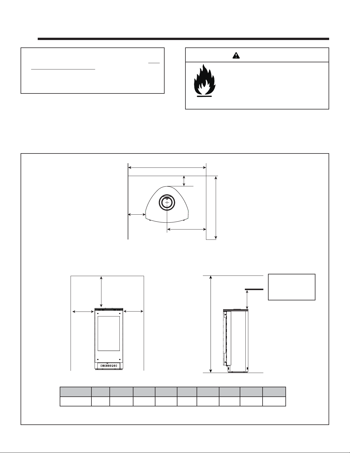
A. Selecting Appliance Location
When selecting a location for your appliance it is important to
consider the required clearances to walls (see fi gure 2.1).
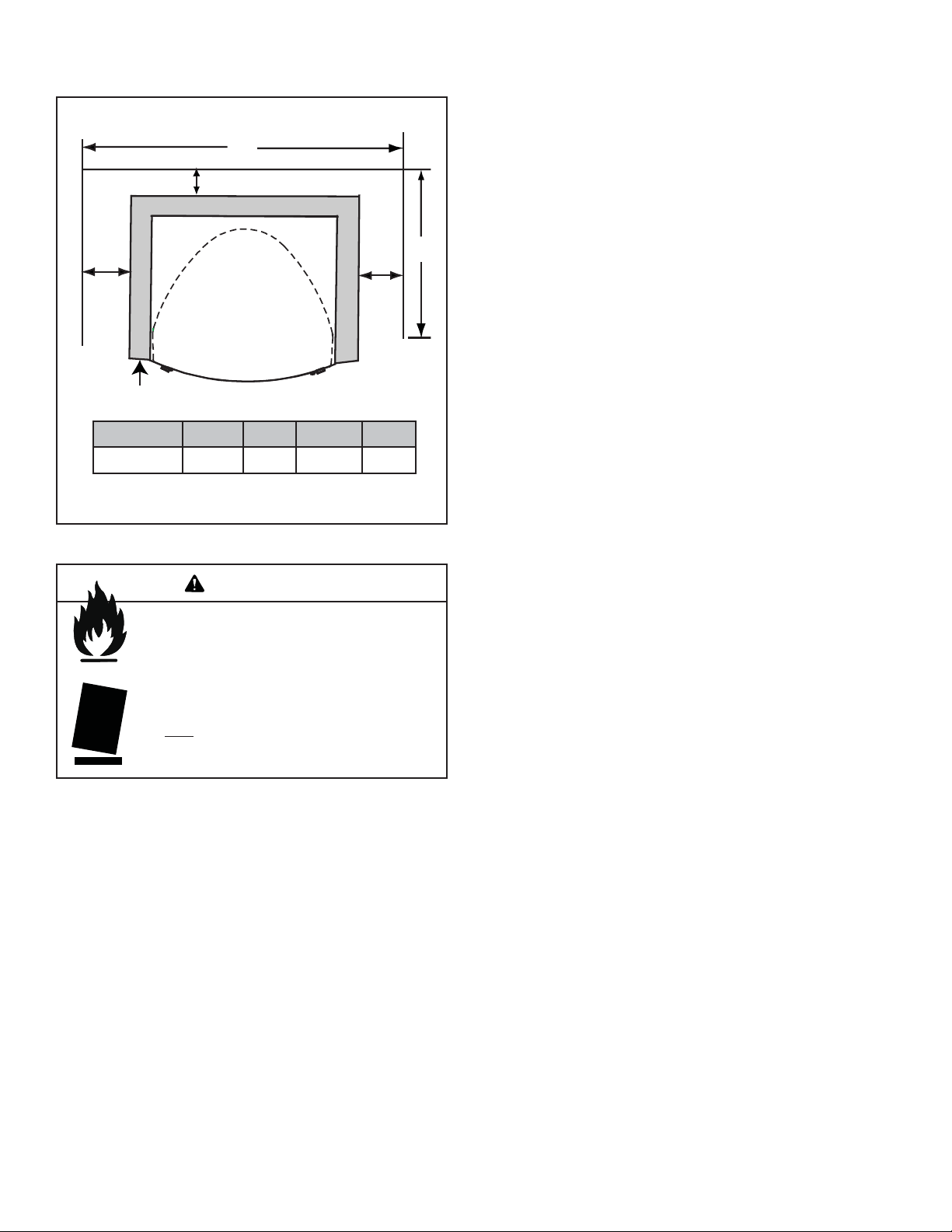
B. Clearances to Combustibles
A
WARNING
Fire Risk
Provide adequate clearance:
• Around air openings
• To combustibles
• For service access
Locate appliance away from traffi c areas.
Note: For actual appliance dimensions refer to Section 12.
F
B
E
I
“A” measurement is from gas stove top, not side.
Alcove
G
H
A
AB C DEFGH I
Millimeters 152 76 308 1372 914 781 337 267 394
A
D
Note: Mantel must
maintain 25mm
clearance from
vertical fl ue.
Figure 2.1
Heat & Glo • VRTIKL-AU • 2123-900 • 7/07
5
Page 6
C. Optional Stone Surround Installed
C
B
D
A
AB C D
Millimeters 83 102 781 914
Figure 2.2
WARNING
Fire Risk.
Odor Risk.
Tipping Risk
• Install gas stove on a stable, level platform/
fl oor strong enough to support gas stove
without tipping.
• USE wood fl ooring, ceramic tile, brick hearth
or high pressure laminate fl ooring applied
directly over the sub-fl ooring material.
A
6 Heat & Glo • VRTIKL-AU • 2123-900 • 7/07
Page 7
3
3
Termination Locations
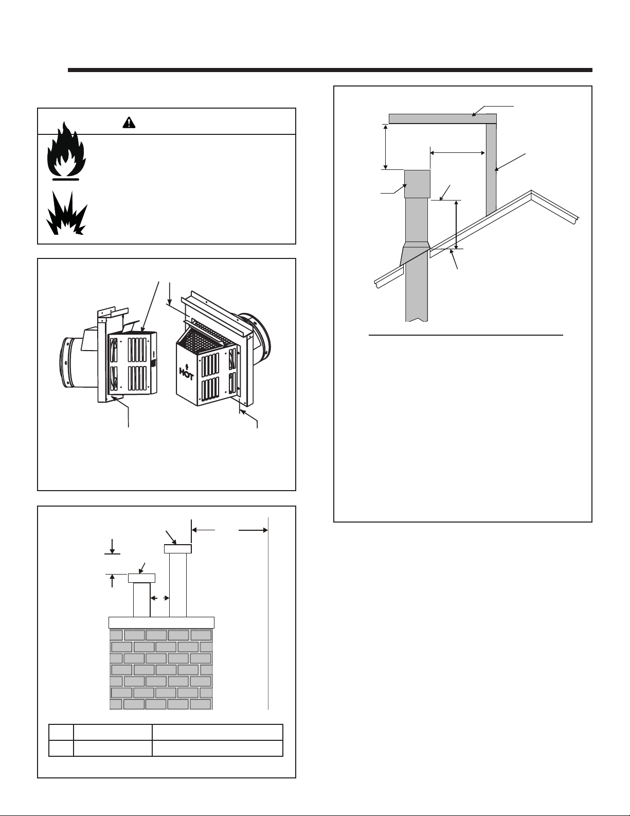
A. Flue Termination Minimum Clearances
WARNING
HORIZONTAL
OVERHANG
Fire Risk.
Explosion Risk.
Maintain fl ue clearance to combustibles as
specifi ed.
• Do not pack air space with insulation or other
materials.
Failure to keep insulation or other materials
away from fl ue pipe may cause fi re.
Measure vertical clearances from this surface.
Measure horizontal clearances from this surface.
(See Figure 3.4 for specifi c clearances)
Figure 3.1
610 mm
TERMINATION
CAP
Angle H (Min.) M
0°-26.6° ........................................................0.30*
26.6°-30.3° ........................................................0.38*
30.3°-33.7° ........................................................0.46*
33.7°-36.9° ........................................................0.61*
36.9°-39.8° ........................................................0.76
39.8°-42.5° ........................................................0.99
42.5°-45.0° ........................................................1.22
45.0°-49.4° ........................................................1.52
49.4°-53.1° ........................................................1.83
53.1°-56.3° ........................................................2.13
56.3°-59.0° ........................................................2.29
59.0°-60.3° ........................................................2.44
*.91 M minimum in snow regions
610 mm
LOWEST
DISCHARGE
OPENING
H (MIN.) - MINIMUM HEIGHT FROM ROOF
TO LOWEST DISCHARGE OPENING
VERTICAL
WALL
GAS, WOOD OR FUEL
460 mm
OIL TERMINATION
GAS
TERMINATION
A
(MINIMUM) TO
PERPENDICULAR
(GAS ONLY)
Gas Termination Wood & Fuel Oil Termination
A 150 mm 510 mm
Figure 3.2 Multiple Vertical Termination
Figure 3.3 Minimum Height from Roof to Lowest Discharge
Opening
610 mm
Figure 3.3 specifi es minimum fl ue heights for various
WALL
Heat & Glo • VRTIKL-AU • 2123-900 • 7/07
pitched roofs.
7
Page 8
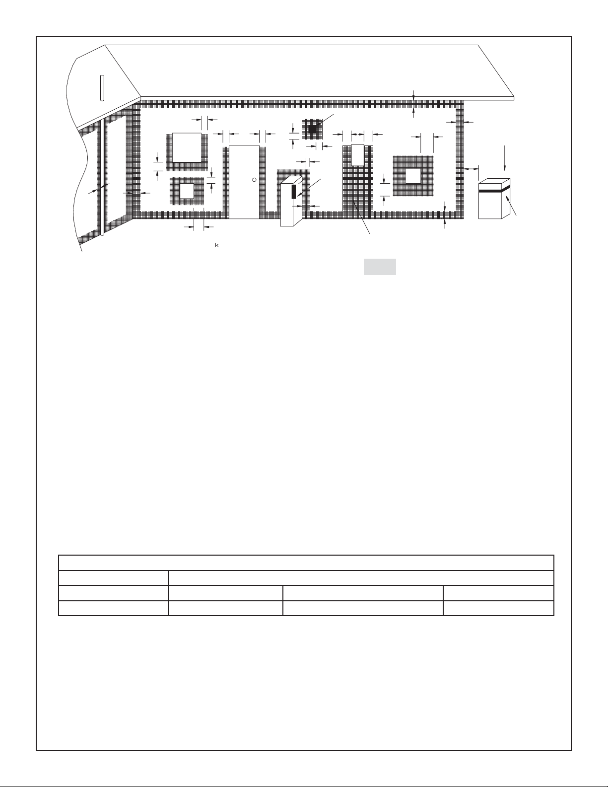
a
h
T
g
T
ee
P
d
See note 2
c
d
M
b
See note 3
g
T
j
openable
window
n
f
c
I
door
k
k
h
jj
h
T = Flue terminal M = Gas meter Shading indicates prohibited
I = Mechanical air inlet P = Electricity meter or fuse box areas for fl ue terminals
a - Below eaves, balconies or other projections: MIN. CLEARANCE (mm)
Appliances up to 50 MJ/h input .........................................................................................300
Appliances over 50 MJ/h input ..........................................................................................500
b - From the ground or above a balcony ....................................................................................300
c - From a return wall or external corner ....................................................................................500
d - From a gas meter (M) .........................................................................................................1000
e - From an electricity meter or fuse box (P) .............................................................................. 500
f - From a drain or soil pipe ....................................................................................................... 150
g - Horizontally from any building structure (unless appliance approved
for closer installation) or obstruction facing a terminal ..........................................................500
h - From any other fl ue terminal, cowl, or combustion air intake ................................................ 500
j - Horizontally from an openable window, door, non-mechanical air
inlet, or any other opening into a building, with the exception of sub-fl oor ventilation:
Appliances up to 150 MJ/h input .......................................................................................500
Appliances over 150 MJ/h input ......................................................................................1500
k - From a mechanical air inlet, including a spa blower ..........................................................1500
n - Vertically below an openable window, non-mechanical air
inlet or any other opening into a building, with the exception of ..................................See table
sub-fl oor ventilation ............................................................................................................below
CLEARANCE ‘n’ (mm)
Space Heaters All other appliances
Up to 50 MJ/h input Up to 50 MJ/h input Over 50 MJ/h & up to 150 MJ/h Over 150 MJ/h input
150 500 1000 1500
NOTES: 1. All distances are measured vertically or horizontally along the wall to a point in line with the nearest
part of the terminal.
2. Prohibited area below electricity meter or fuse box extends to ground level.
3. See clause 5.13.6.6 for restrictions on a fl ue terminal under a roofed area.
4. See Appendix J, Figure J1(a) and J2(a) for clearances required from a fl ue terminal to a LP Gas
cylinder. A fl ue terminal is considered to be a source of ignition.
MINIMUM CLEARANCES REQUIRED FOR BALANCED FLUE TERMINALS
OR THE FLUE TERMINALS OF OUTDOOR APPLIANCES
8 Heat & Glo • VRTIKL-AU • 2123-900 • 7/07
Page 9
4
4
Flue Information
A. Flue Components
This model is approved for use with Simpson Dura-Vent
pipes, components and terminations. Approved components are labeled for identifi cation. This fl ue is tested and
listed as an approved component of the stove.
DO NOT USE FIELD-FABRICATED FLUE COMPONENTS.
Refer to the flue manufacturer’s instructions.
This product is approved to be flued either horizontally
through the side wall or vertically through the roof. You
may flue through a Class A or masonry chimney if an
approved adapter is used.
This gas stove is a balanced fl ue gas stove. All combus-
tion air must come directly from the outside of the building. The fl ue pipe for this unit consists of an inner and an
outer pipe. The inner pipe carries the gas stove exhaust
out of the system, and the outer pipe brings fresh combustion air into the gas stove.
• A heat shield is required when the fl ue pipe passes
through a combustible wall.
• A support box or ceiling fi restop is required when the
venting passes through a ceiling.
• Roof fl ashing and a storm collar are required when fl ue
pipe passes through the roof.
• Follow instructions provided with the fl ue pipe for instal-
lation of these items.
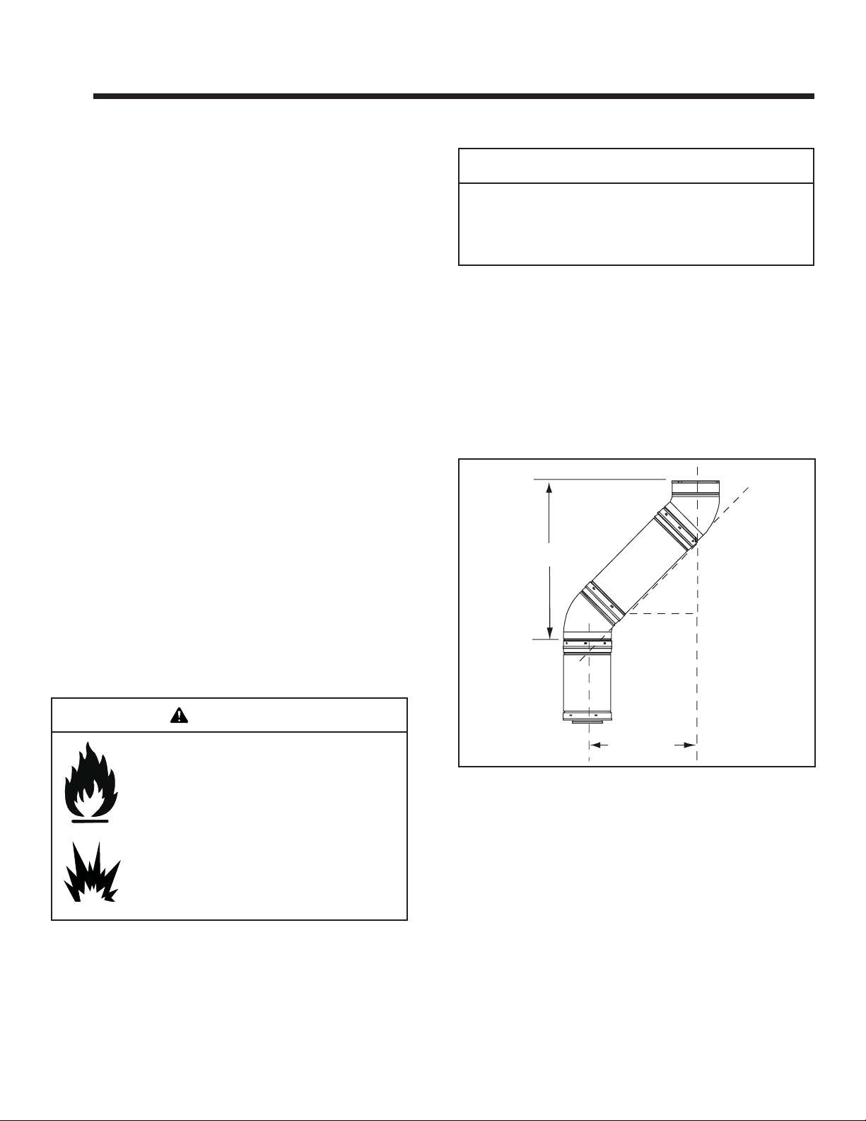
B. Use of Elbows
CAUTION
ALL fl ue confi guration specifi cations MUST be followed.
• This product is tested and listed to these specifi cations.
• Appliance performance will suffer if specifi cations are not
followed.
Diagonal runs have both vertical and horizontal vent aspects when calculating the effects. Use the rise for the
vertical aspect and the run for the horizontal aspect (see
Figure 4.1).
Two 45º elbows may be used in place of one 90º elbow . On
45º runs, one foot of diagonal is equal to 216 mm horizontal
run and 216 mm vertical run. A length of straight pipe is
allowed between two 45º elbows (see Figure 4.1).
Vertical
305 mm
216 mm
216 mm
WARNING
Fire Hazard.
Explosion Risk.
Asphyxiation Risk.
Do NOT connect this gas appliance to a chimney
fl ue serving a separate solid-fuel or gas burning
appliance.
• Flue this appliance directly outside.
• Use separate fl ue system for this appliance.
May impair safe operation of this appliance or
other appliances connected to the fl ue.
Heat & Glo • VRTIKL-AU • 2123-900 • 7/07
Figure 4.1
Horizontal
C. Measuring Standards
Vertical and horizontal measurements were made using
the following standards.
1. Pipe measurements are from center line to center line.
2. Horizontal terminations are measured to the outside
mounting surface (fl ange of termination cap). See
Figure 3.1 on page 7.
3. Horizontal pipe installed level with no rise.
9
Page 10
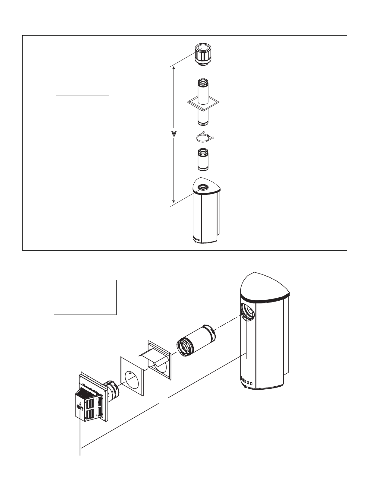
D. Flue Diagrams
STRAIGHT UP
VERTICAL FLUE
V
3.6M Minimum
11.8M Maximum
For Natural and Propane Gases.
V
Figure 4.2
STRAIGHT OUT
HORIZONTAL FLUE
H
610 mm Maximum
For Natural and Propane Gases.
H
Figure 4.3
10 Heat & Glo • VRTIKL-AU • 2123-900 • 7/07
Page 11
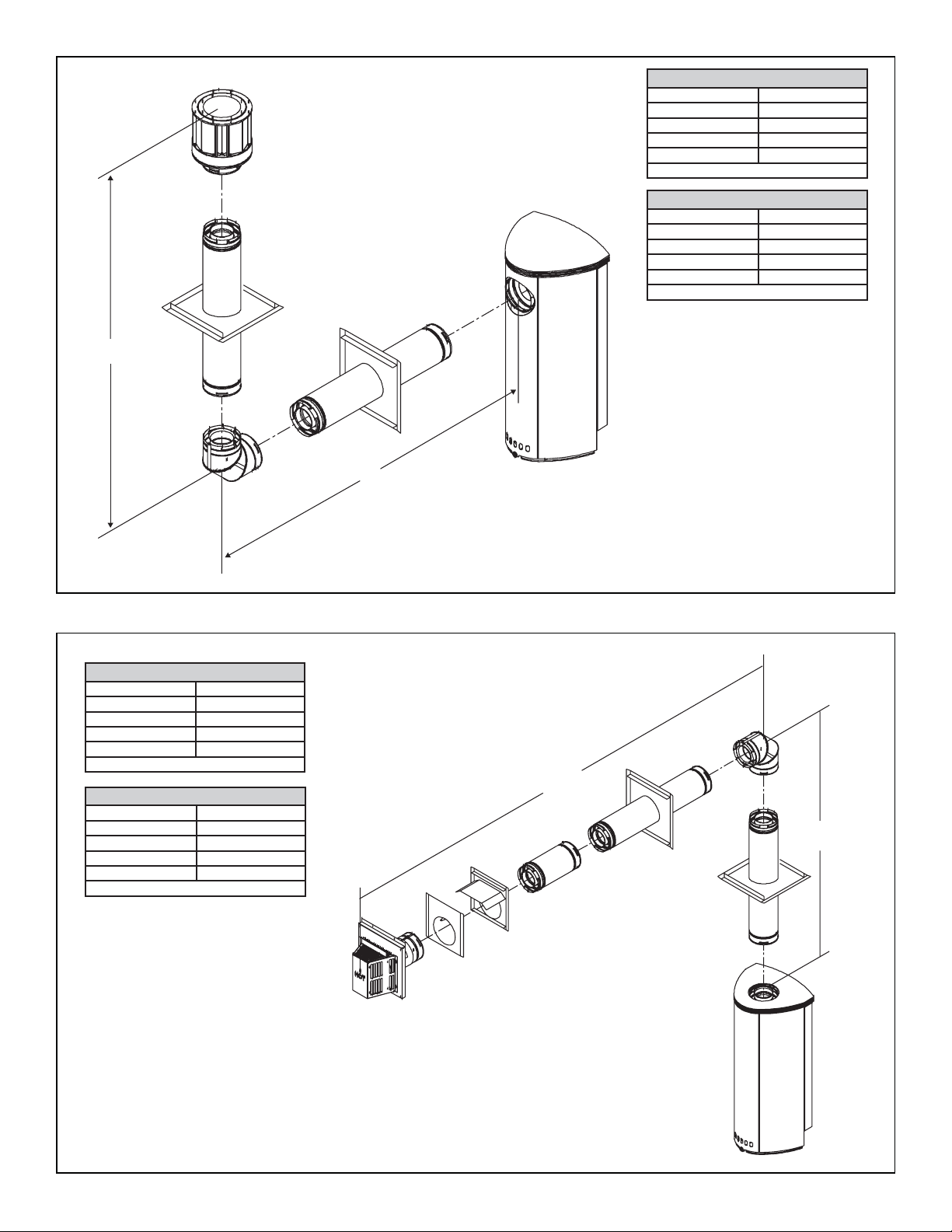
Natural Gas • One 900 Elbow System
V Minimum H Maximum
460 mm 1.3 M
920 mm 2.7 M
1.4 M 4.1 M
1.8 M 5.0 M
V+H = Max 11.6 M H Max = 5.0 M
Propane • One 900 Elbow System
V Minimum H Maximum
460 mm 920 mm
920 mm 1.8 M
1.4 M 2.8 M
1.8 M 3.6 M
V+H = Max 11.6 M H Max = 3.6 M
V
H
Figure 4.4
Natural Gas • One 900 Elbow System
V Minimum H Maximum
460 mm 1.3 M
920 mm 2.7 M
1.4 M 4.1M
1.8 M 5.0 M
V+H = Max 11 M H Max = 5.0 M
Propane • One 900 Elbow System
V Minimum H Maximum
460 mm 920 mm
920 mm 1.8 M
1.4 M 2.8 M
1.8 M 3.6 M
V+H = Max 11 M H Max = 3.6 M
H
V
Figure 4.5
Heat & Glo • VRTIKL-AU • 2123-900 • 7/07
11
Page 12
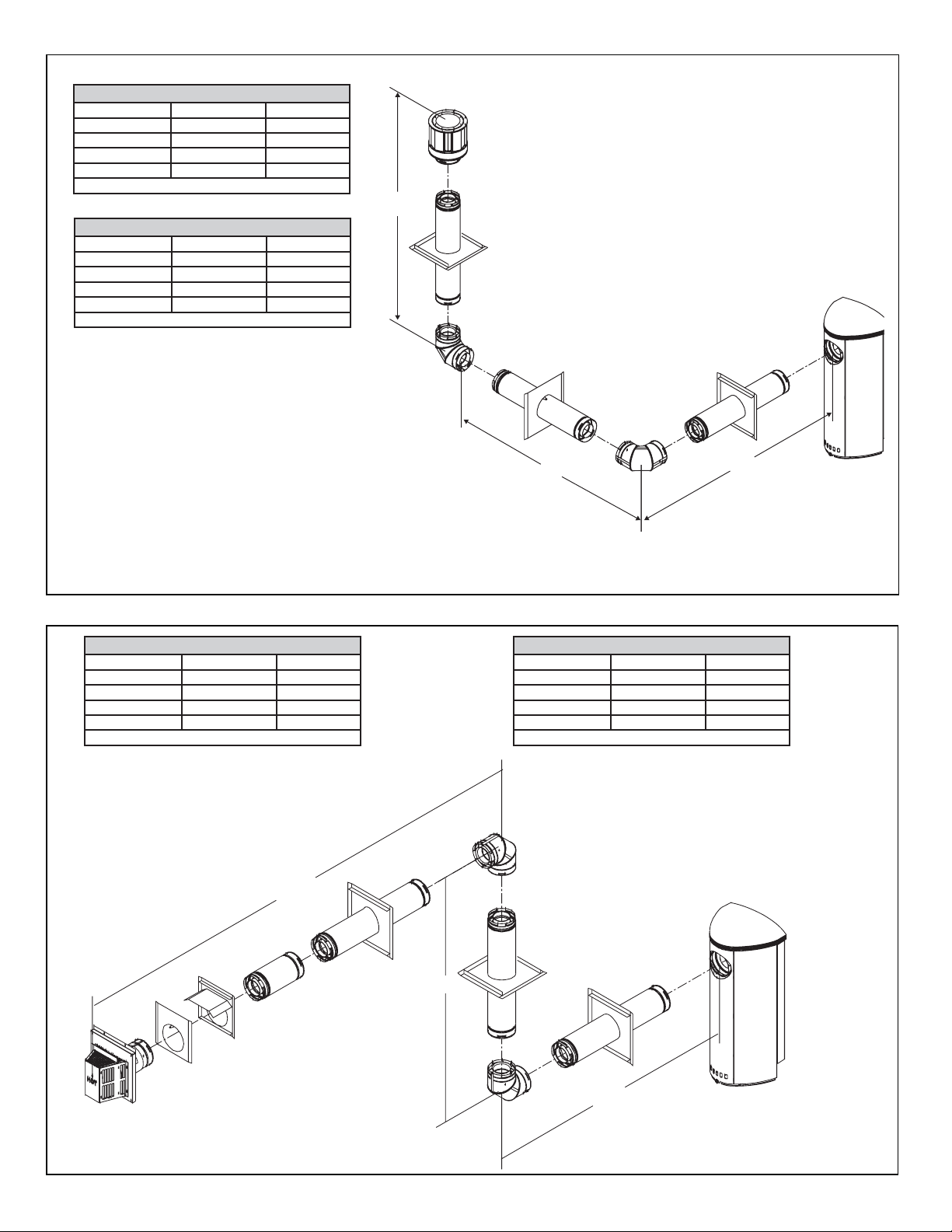
Natural Gas • Two 900 Elbows System
V Min. H1 Max. H1 + H2 Max.
460 mm 550 mm 1.1 M
920 mm 1.1 M 2.2 M
1.4 M 1.7 M 3.5 M
1.8 M 2.2 M 4.5 M
V+H1+H2 = Max 11.0M H1 Max = 2.2M H1+H2 = Max 4.5M
Propane • Two 900 Elbows System
V Min. H1 Max. H1 + H2 Max.
460 mm 390 mm 690 mm
920 mm 750 mm 1.3 M
1.4 M 1.1 M 2.1 M
1.8 M 1.5 M 2.7 M
V+H1+H2 = Max 10.6M H1 Max = 1.5M H1+H2 = Max 2.7M
V
Figure 4.6
Natural Gas • Two 900 Elbows System
V Min. H1 Max. H1 + H2 Max.
460 mm 550 mm 1.1 M
920 mm 1.1 M 2.3 M
1.4 M 1.7 M 3.5 M
1.8 M 2.2 M 4.5 M
V+H1+H2 = Max 10M H1 Max = 2.2M H1+H2 = Max 4.5M
H2
H2
Propane • Two 900 Elbows System
V Min. H1 Max. H1 + H2 Max.
460 mm 390 mm 690 mm
920 mm 750 mm 1.3 M
1.4 M 1.1 M 2.1 M
1.8 M 1.5 M 2.7 M
V+H1+H2 = Max 10M H1 Max = 1.5M H1+H2 = Max 2.7M
H1
V
Figure 4.7
12 Heat & Glo • VRTIKL-AU • 2123-900 • 7/07
H1
Page 13

V2
H
V1
Natural Gas • Two 900 Elbows System
V1 Min. H Max.
310 mm 930 mm
610 mm 1.8 M
91 cm 2.7 M
1.2 M 3.6 M
1.5 M 4.5 M
V1+V2+H = Max 11.4M H Max = 4.5M
Propane • Two 900 Elbows System
V1 Min. H Max.
310 mm 620 mm
610 mm 1.2 M
910 mm 1.8 M
1.2 M 2.4 M
1.5 M 3.0 M
V1+V2+H = Max 11.4M H Max = 3.0M
Figure 4.8
Natural Gas • Two 900 Elbows System
V Min. H1+H2 Max.
61 cm 1.6 M
91 cm 2.4 M
1.2 M 3.2 M
1.5 M 4.0 M
V+H1+H2 = Max 11.4M H1+H2 = Max 4.0M
Propane • Two 900 Elbows System
V Min. H1+H2 Max.
61 cm 1.0 M
91 cm 1.5 M
1.2 M 2.0 M
1.5 M 2.6 M
V+H1+H2 = Max 11.4M H1+H2 = Max 2.6M
H2
H1
V
Figure 4.9
Heat & Glo • VRTIKL-AU • 2123-900 • 7/07
13
Page 14

Natural Gas • Three 900 Elbows System
V1 Min. H1 Max. H1 + H2 Max.
460 mm 550 mm 1.1 M
920 mm 1.1 M 2.3 M
1.4 M 1.7 M 3.5 M
1.8 M 2.2 M 4.5 M
V1+V2+H1+H2=Max11M H1 Max=2.2M H1+H2=Max 4.5M
Propane • Three 900 Elbows System
V1 Min. H1 Max. H1 + H2 Max.
460 mm 340 mm 690 mm
920 mm 650 mm 1.3 M
1.4 M 1.0 M 2.1 M
1.8 M 1.8 M 2.7 M
V1+V2+H1+H2=Max 11M H1 Max=1.8M H1+H2=Max 2.7M
V2
H2
V1
H1
Figure 4.10
V2
H2
Natural Gas • Three 900 Elbows System
V1 Min. H1 Max. H1 + H2 Max.
460 mm 550 mm 1.0 M
920 mm 1.1 M 2.0 M
1.4 M 1.7 M 3.0 M
1.8 M 2.2 M 3.9 M
V1+V2+H1+H2=Max 11M H1 Max=2.2M H1+H2=Max 3.9M
Propane • Three 900 Elbows System
V1 Min. H1 Max. H1 + H2 Max.
460 mm 340 mm 550 mm
920 mm 650 mm 1.1 M
1.4 M 1.0 M 1.6 M
1.8 M 1.8 M 2.1 M
V1+V2+H1+H2=Max 10M H1 Max=1.8M H1+H2=Max 2.1M
V1
H1
Figure 4.11
14 Heat & Glo • VRTIKL-AU • 2123-900 • 7/07
Page 15

E. Horizontal Termination
HEAT SHIELD
PIPE LENGTH
PIPE LENGTH
TERMINATION CAP
WALL
CENTER LINE
Figure 4.12
90 DEGREE
ELBOW
Step 1.
Determine the desired location of the gas stove. Check
to ensure that wall studs or roof rafters are not in the way
when the flue system is being planned. If this is the case,
you may want to adjust the location of the gas stove.
FEMALE LOCKING LUGS
MALE LOCKING LUGS
Figure 4.13
WARNING
Fire Risk.
Explosion Risk.
Combustion Fume Risk.
Use fl ue run supports per installation in-
structions.
Connect fl ue sections per installation in-
structions.
• Maintain all clearances to combustibles.
• Do NOT allow fl ue to sag below
connection point to appliance.
• Maintain specifi ed slope (if required).
Improper support may allow fl ue to sag or separate.
WARNING
Fire Risk
Exhaust Fumes Risk
Impaired Performance of Appliance
• Ensure flue components are locked
together correctly.
• Pipe may separate if not properly joined.
Step 2.
Balanced flue pipe is designed with a locking connection.
To connect the flue system to the gas stove flue outlet, a
twist-lock adapter is built into the gas stove at the factory.
Wall thickness may vary. Remember to include wall
thickness in minimum clearances when figuring flueing
lengths for your installation needs.
Note: Female ends of balanced flue pipe/elbows are
designed to slide straight onto the male ends of adjacent
pipes by orienting the pipe indentations so they match
and slide into the entry slots on the male ends, see Figure
4.13. Push the pipe sections completely together, then
twist-lock one section clockwise approximately one-quarter turn, until the two sections are fully locked. The female
locking lugs may not be visible from the outside. They may
be located by examining the inside of the female ends.
Step 3.
For installations using a slim line heat shield (check pipe
manufacturer's instructions), mark the outside wall for a
254 mm x 254 mm square hole. The center of the square
hole should line up with the center line of the horizontal
pipe, as shown in Figure 4.12. Cut and frame the hole in
the exterior wall where the flue will be terminated. If the
wall being penetrated is constructed of noncombustible
material, i.e. masonry block or concrete, a 178 mm diameter hole is acceptable.
Step 4.
Install slim line heat shield as shown in Section 4F.
Step 5.
Position the horizontal termination cap in the center of
the 254 mm x 254 mm square hole and run a bead of
non-hardening mastic around its outside edges, to make
a seal between it and the wall. Attach termination cap to
the exterior wall with the four wood screws provided. The
arrow on the flue cap should be pointing up.
Heat & Glo • VRTIKL-AU • 2123-900 • 7/07
15
Page 16

F. Slim Line Heat Shield
BEFORE YOU BEGIN:
Review the fl ueing confi gurations in Figures A and B on
the next page.
1. Assembling Slim Line Trim Ring and Heat
Shield
Figure 4.14
Lay the trim ring on fl at surface and bend up the six
welded brackets into a 90 degree position. The brackets
along the outer edge of the ring are for locating the ring in
the center of the hole.
Figure 4.16
Attach the heat shield to the trim ring with the four screws
provided. Screws go through the heat shield and into the
brackets on the trim ring.
2. Installing Slim Line Trim Ring and Heat Shield
Measure from the fl oor to the center of the fl ue pipe. Cut
out a 241 mm diameter round hole in the wall. Hold the
trim ring/heat shield assembly in place and put a mark on
the shield with a black marker where it protrudes through
the exterior wall. See Figure 4.12 on previous page.
Use that mark as a guide to trim off excess heat shield
with a pair of sheet metal shears.
Figure 4.17
Figure 4.15
The heat shield is shipped fl at and must be hand bent into
a half circle before attaching it to the trim ring. Bend the
heat shield as shown.
When installing the trim ring/heat shield assembly make
sure the trim ring is centered in the hole and that the
shield is above the pipe. There must be a minimum of 19
mm clearance maintained to combustibles from the top of
the heat shield.
Ensure that framing on the inside of the wall is a minimum
CAUTION
Sharp Edges
• Wear protective gloves and safety
glasses during installation.
inner framing diameter of 254 mm x 254 mm.
The four trim ring mounting screws provided should be
replaced with appropriate fasteners for stucco, brick,
concrete, or other types of sidings. The trim ring may be
sealed with high temperature caulk or high temperature
adhesive.
16 Heat & Glo • VRTIKL-AU • 2123-900 • 7/07
Page 17

FIG. A 90 DEGREE ELBOW
L
Place mark where protrudes through
exterior wall to cut off excess.
O
90 ELBOW
CENTER
LINE
USE HEAT SHIELD
PIPE
LENGTH
TRIM
RING
PIPE LENGTH
FIG. B MINIMUM CLEARANCE
INTERIOR WALL
76mm CLEARANCE
FROM REAR OF STOVE
CENTER LINE
Figure 4.18
MINIMUM OF 152 mm
OF PIPE THROUGH THE WAL
HEAT SHIELD OVER
TOP HALF OF PIPE
TRIM RING
Heat & Glo • VRTIKL-AU • 2123-900 • 7/07
17
Page 18

G. Vertical Termination
1. Balanced Flue Pipe
STORM COLLAR
VERTICAL
TERMINATION CAP
FLASHING
FIRESTOP
SUPPORT BOX
PIPE LENGTH
On vertical terminations use only Part #SLK-991DA
Figure 4.19
Step 1.
Check the installation instructions for required 25 mm
clearances (air space) to combustibles when passing
through ceilings, walls, roofs, enclosures, attic rafters, or
other nearby combustible surfaces. (See Figure 4.14).
Check the instructions for maximum vertical rise of the
flueing system, and any maximum horizontal offset limitations. All offsets must fall within the set parameters of
the flue charts (Figure 4.2) located on pages 11-15.
11.8M
MAXIMUM
Figure 4.20
Step 2.
Set the gas stove in its desired location. Drop a plumb
bob down from the ceiling to the position of the gas
stove flue exit, and mark the location where the flue will
penetrate the ceiling. Drill a small hole at this point. Next,
drop a plumb bob from the roof to the hole previously
drilled in the ceiling, and mark the spot where the flue will
penetrate the roof. Determine if ceiling joists, roof rafters,
or other framing will obstruct the flueing system. Y ou may
wish to relocate the gas stove, or to offset, as shown in
Figure 4.21 to avoid cutting load bearing members.
Note: Maximum vertical rise allowable is 1 1.8 m, Figure 4.2.
WARNING
Fire Risk.
Explosion Risk.
Maintain fl ue clearance to combustibles as
specifi ed.
• Do not pack air space with insulation or other
materials.
Failure to keep insulation or other materials
away from fl ue pipe may cause fi re.
Figure 4.21
18 Heat & Glo • VRTIKL-AU • 2123-900 • 7/07
METAL STRAP
CONNECTED TO
WALL STRAP
WALL
STRAP
TWO 45 DEGREE
ELBOWS
Page 19

Step 3.
To install the round support box/wall thimble cover in
a flat ceiling, cut a 254 mm square hole in the ceiling,
centered on the hole drilled in Step 2. Frame the hole as
shown in Figure 5.22.
CEILING JOISTS
FRAMING
SHINGLES OVERLAP ON
TOP EDGE OF FLASHING
ROUND CEILING
SUPPORT BOX/WALL
THIMBLE COVER
40 mm LONG
WOOD SCREWS
Figure 4.22
Step 4.
Assemble the desired lengths of pipe and elbows necessary
to reach from the gas stove up through the round support
box. Ensure that all pipe and elbow connections are in
their fully twist-locked position. Assemble as instructed.
Step 5.
Cut a hole in the roof centered on the small drill hole
placed in the roof in Step 2. The hole should be of sufficient
size to meet the minimum requirements for clearance
to combustibles, as specified. Continue to assemble
lengths of pipe and elbows necessary to reach from the
ceiling support box/wall thimble up through the roof line.
Galvanized pipe and elbows may be utilized in the attic,
as well as above the roofline. The galvanized finish is
desirable above the roofline, due to its higher corrosion
resistance (compared to black pipe).
CAP AND STORM COLLAR NOT SHOWN FOR CLARITY
Figure 4.23
Step 7.
Continue to assemble pipe sections until the height of
the flue (before adding the termination cap) meets the
minimum local code requirements. Note that for steep
roof pitches, the flue height must be increased. See Roof
Pitch Table (Figure 3.3). In high wind conditions, nearby
trees adjoining rooflines, steep pitched roofs, and other
similar factors can result in poor draft, or down drafting. In
these cases increasing the flue height or switching to the
high wind termination cap may solve this problem.
Step 8.
Slip the storm collar over the pipe, and push it down to
the top of the flashing (Figure 4.24). Use non-hardening
sealant above and below the joint between the storm
collar and the pipe.
SECURE FLASHING WITH
NON-HARDENING SEALANT
AND ROOFING NAILS
NOTE:
(1) If an offset is necessary in the attic to avoid
obstructions, it is important to support the flue pipe
every 914 mm to avoid excessive stress on the
elbows, and possible separation. Wall straps are
available for this purpose, Figure 4.10, page 15.
(2) Whenever possible, use 45° elbows, instead of 90°
elbows. The 45° elbow offers less restriction to the
flow of flue gases and intake air.
Step 6.
Slip the flashing over the pipe section(s) protruding through
the roof. Secure the base of the flashing to the roof with
roofing nails. Ensure the roofing material overlaps the top
edge of the flashing as shown in Figure 4.23. Verify that
the chimney is the required height above the roof. See
roof pitch table, Figure 3.3.
Heat & Glo • VRTIKL-AU • 2123-900 • 7/07
Figure 4.24
19
Page 20

Step 9.
Twist-lock the flue cap and seal.
Note: For multi-story vertical installations, a ceiling firestop
is required at the second floor, and any subsequent floors
(Figure 4.25). The opening should be framed to 254 mm
x 254 mm inside dimensions, in the same manner as
shown in Figure 4.22.
NAILS
CEILING FIRESTOP
MINIMUM 25mm
CLEARANCE
MINIMUM 25mm
CLEARANCE
MINIMUM 25mm
CLEARANCE
H. Vertical Flue Restrictor
If the heater installation requires a vertical flue off the top
of the unit with no horizontal flue or elbows, the vertical
flue restrictor must be added. Reinstall heat shield when
completed. See Figure 4.26.
VRTKL-AU: FLUE RESTRICTOR PLATE INSTALLATION
FLUE
RESTRICTOR
PLATE
HEAT SHIELD
Figure 4.26
Figure 4.25
MINIMUM 25mm
CLEARANCE
WARNING
Fire Risk.
Explosion Risk.
• Any occupied areas above the first floor,
including closets and storage spaces, which
the vertical flue passed through must be
enclosed. The enclosure may be framed
and sheetrocked with standard construction
materials; however, refer to these installation
instructions for the minimum allowable
clearance between the outside of the flue
pipe and the combustible surfaces of the
enclosure. Do not fill any of the required air
space with insulation.
20 Heat & Glo • VRTIKL-AU • 2123-900 • 7/07
Page 21

5
5
Gas Information
A. Gas Pressure Requirements
Pressure requirements for VRTIKL-AU Stoves are shown
in Table 1 below.
Two taps are provided on the right hand side of the gas
control for a test gauge connection to measure the inlet
and outlet pressures. See Section 10: Maintaining and
Servicing the Appliance.
The stove and its individual shut-off valve must be disconnected from the gas supply piping system during any
pressure testing of the system at test pressures in excess
of 60 mbar.
If the stove must be isolated from the gas supply piping
system by closing an individual shut-off valve, it must be
of the handle-less type.
WARNING
Fire Risk.
Explosion Hazard.
High pressure will damage valve.
• Disconnect gas supply piping BEFORE
pressure testing gas line at test pressures
above 6 kPa.
• Close the manual shutoff valve BEFORE
pressure testing gas line at test pressures
equal to or less than 6kPa..
Table 1
B. Gas Connection
Note: Have the gas supply line installed in accordance with
local building codes by a qualifi ed installer approved and/or
licensed as required by the locality.
Note: Before the fi rst fi ring of the stove, the gas supply line
should be purged of any trapped air.
Leak test all gas line points and the gas control valve prior
to and after starting the gas stove.
WARNING
CHECK FOR GAS LEAKS
Explosion Risk
Fire Risk
Asphyxiation Risk
• Check all fi ttings and connections.
• Do not use open fl ame.
• After the gas line installation is complete, all
connections must be tightened and checked
for leaks with a commercially-available,
non-corrosive leak check solution. Be sure
to rinse off all leak check solution following
testing.
Fittings and connections may have loosened
during shipping and handling.
Natural Gas Propane
Minimum Inlet Pressure 1.13 kPa 2.75 kPa
Outlet Pressure .80 kPa 2.40 kPa
Max. Gas Consumption 26.7 mJ 24.5 mJ
Burner Injector 2.53 mm 1.45 mm
Heat & Glo • VRTIKL-AU • 2123-900 • 7/07
21
Page 22

6
6
Electrical Information
A. Ignition System Wiring
• This gas stove is equipped with an electronic ignition
system which operates on a 6 volt system.
• The batteries are located within the ignition module
which is located behind the glass door assembly . A wiring
diagram is shown in Figure 7.1.
• The ignition module requires four AA batteries (not
included).
WARNING
Shock hazard.
• Replace damaged wire with type 105º C rated
wire.
• Wire must have high temperature insulation.
CAUTION
CAUTION
Battery polarity must be correct or module damage will
occur.
PILOT
IGNITION MODULE
6VDC
Label all wires prior to disconnection when servicing controls.
Wiring errors can cause improper and dangerous operation.
Verify proper operation after servicing.
FLAME SPARKER/
SENSOR
REMOTE
CONTROL
ANT.
VALVE
ON/OFF
WALL SWITCH
IGNITION
MODULE
(6V)
BATTERY PORT
(4 AA BATTERIES)
ON/OFF
SWITCH
PILOT GAS LINE
CONNECTED TO
BACK OF VALVE
Figure 6.1 Electronic Ignition Wiring Diagram
22 Heat & Glo • VRTIKL-AU • 2123-900 • 7/07
THERMOCOUPLE
BLOCK
(CONNECTED TO
BACK OF VALVE)
VALVE
Page 23

ALLEN HEAD SCREWS
LEVELING
SCREWS
LAG BOLT
HOLE
7
7
Appliance Setup
A. Remove Glass Door
Remove the front door assembly by pulling bottom of front
away from gas stove and lifting it off of the hooks on top of
the stove. Set door assembly aside.
B. Remove Shipping Materials
Remove shipping materials from inside or underneath the
fi rebox.
The gas line is shipped inside back panel. To access the
gas line remove the top plate from the gas stove. Remove
and retain the two Allen head screws that hold the back
panel in place. Replace panel when fi nished.
ALLEN HEAD SCREWS
D. Leveling and Lagging Down the Appliance
SECURING THE GAS STOVE
IS REQUIRED.
WARNING
Fire Risk.
Odor Risk.
Tipping Risk
• Install gas stove on a stable, level platform/
fl oor strong enough to support gas stove
without tipping.
• USE wood fl ooring, ceramic tile, brick hearth
or high pressure laminate fl ooring applied
directly over the sub-fl ooring material.
LEVELING
SCREWS
LAG BOLT
HOLE
Figure 7.1
C. Unbolting Appliance from the Pallet
The gas stove is bolted and screwed to the pallet for shipping. Use a 1/2 in. socket to remove the bolt in center of
bottom plate. Use a Phillips screwdriver to remove the
two screws in the front of the bottom plate and the two
screws holding the metal strap across the back of the gas
stove. Refer to Figure 7.2 for locations.
Figure 7.2
Heat & Glo • VRTIKL-AU • 2123-900 • 7/07
Figure 7.3
After unbolting the gas stove from the pallet, insert two
1/4 20 x 1-1/2 (or equivalent) counterscrews.
Using pliers, adjust the counterscrews to level the gas
stove.
23
Page 24

CLEARANCE
IINNER EXTENSION COLLAR
DV ADAPTER
ALLENHEAD
SCREWS
HOLE
Figure 7.4
The manufacturer recommends securing the lag bolt
from the component bag in the center hole in the bottom
plate (clearance hole). This bolt will help to prevent tipping forward.
F. Top to Rear Flue Conversion
KIT CONTENTS: Top cover (without hole);
Back panel (with hole).
1. Remove the front door assembly by pulling bottom
of front away from gas stove and lifting it off of the
hooks on top of the gas stove. Set door aside.
ON TOP OF APPLIANCE:
2. Remove the top plate with hole and discard. (Figure 7.7)
Figure 7.5
Using pliers, adjust the counter screws to level the gas
stove.
E. Accessories
Install approved accessories per instructions included
with accessories.
WARNING
Shock or fi re risk.
Use ONLY optional accessories approved for
this appliance.
• Using non-listed accessories voids warranty.
• Using non-listed accessories may result in a
safety hazard.
• Only Hearth & Home Technologies approved
accessories may be used safely.
Figure 7.7
3. Remove and retain the Allen head screws that hold
the solid back panel in place (Figure 7.8). Remove
and discard the solid back panel.
NNER EXTENSION COLLAR
DV ADAPTER
ALLENHEAD
SCREWS
Figure 7.8
4. Remove the inner extension collar (Shown in Figure
7.8) and set aside.
5. Remove the four screws from the DV adapter collar
(Figure 7.8). Set aside DV adapter collar and
screws.
24 Heat & Glo • VRTIKL-AU • 2123-900 • 7/07
Page 25

ON BACK OF APPLIANCE:
IINNER EXTENSION COLLAR
6. Remove the four screws from the cover plate on rear
of gas stove. Set cover plate aside. Retain screws.
(See Figure 7.9). Attach DV adapter collar in its
place. Install the inner extension collar.
NNER EXTENSION COLLAR
Figure 7.9
7. Install the cover plate with gasket to the top of gas stove
with screws previously removed (Figure 7.10).
ON TOP OF APPLIANCE:
8. Install the new back panel (without hole) to the rear of
gas stove. Replace the Allen head screws removed
in Step 3 to hold the back panel in place.
9. Install the new top as shown in Figure 7.11.
Figure 7.11
Figure 7.10
Heat & Glo • VRTIKL-AU • 2123-900 • 7/07
25
Page 26

G. Positioning the Logs
While still breakable, the logs do not become fragile until
after the gas stove is burned and they have cured. After
curing, any handling must be done with care as breakage
can easily occur.
PLEASE NOTE: Logs have been designed to work
specifically with the burner of this gas stove. Exact
placement will ensure proper operation of your gas
stove.
Figure 7.13
Figure 7.15
Locate log #2 over the pin in log #1 and into notch in log
#1. Lean the log back toward the left corner of the firebox.
H. Placing Mineral Wool
WARNING
Explosion Risk.
• Follow ember placement instructions in manual.
• Do NOT place embers directly over burner ports.
• Replace ember material annually.
Improperly placed embers interferes with proper burner
operation.
Figure 7.14
Place log #1 into the cradle in the burner. Lean the log
back towards right corner of firebox.
26 Heat & Glo • VRTIKL-AU • 2123-900 • 7/07
Figure 7.16
Apply 15 mm size pieces sparingly along ports as shown.
Do not block ports.
Page 27

8
8
Operating Instructions
A. Before Lighting Appliance
Read this entire manual prior to using the appliance.
Failure to follow the instructions may result in property
damage, bodily injury, or even death.
• Remove all shipping materials from inside and/or
underneath the fi rebox.
• Review proper placement of logs and mineral wool.
• Check the wiring.
• Check the baffl e adjustment.
• Ensure that there are no gas leaks.
• Ensure that the glass is sealed and in the proper
position.
• Ensure that the fl ow of combustion and ventilation air is
not obstructed (front grilles and fl ue terminations).
WARNING
Glass door must be in place when
appliance is operating.
Risk of:
• Combustion Fumes
• Fire
Do NOT operate appliance with glass
door removed.
• Open viewing glass for servicing only.
• Glass door MUST be in place and sealed before operating
appliance.
• Only use glass door certifi ed for use with appliance.
• Glass replacement should be done by qualifi ed technician.
WARNING
HOT! DO NOT TOUCH.
SEVERE BURNS MAY RESULT.
CLOTHING IGNITION MAY RESULT.
Glass and other surfaces are hot during operation and cool
down.
• Keep children away.
• CAREFULLY SUPERVISE children in same room as appliance.
• Alert children and adults to hazards of high temperatures.
• Do NOT operate with protective barriers open or removed.
• Keep clothing, furniture, draperies and other combustibles
away .
WARNING
Improper installation, adjustment, alteration, service or
maintenance can cause injury or property damage. Refer to
the owner’s information manual provided with this appliance.
For assistance or additional information consult a qualifi ed
installer, service agency or the gas supplier.
WARNING
Do NOT use this appliance if any part has been under water.
Immediately call a qualifi ed service technician to inspect the
appliance and to replace any part of the control system and
any gas control which has been under water.
WARNING
Risk of Fire
Risk of Burns
• Do not remove guard. The guard is fi tted
to this appliance to reduce the risk of fi re
or injury from burns and no part of it should
be permanently removed. For protection of
young children or the infi rm, a secondary
guard is required.
Heat & Glo • VRTIKL-AU • 2123-900 • 7/07
WARNING
Risk of Fire
Risk of Burns
• Do not place articles on or against this
appliance.
• Do not use or store fl ammable materials near
this appliance.
• Do not spray aerosols in the vicinity of this
appliance while it is in operation.
27
Page 28

B. Lighting the Appliance
Electronic Ignition
FOR YOUR SAFETY
READ BEFORE LIGHTING
WARNING: If you do not follow these instructions
exactly, a fi re or explosion may result causing property
damage, personal injury or loss of life.
A. This heater is equipped with an
electronic pilot ignition device
which automatically lights the
burner. Do not try to light the
burner by hand.
B. BEFORE LIGHTING, smell all
around the heater area for gas.
Be sure to smell next to the fl oor
because some gas is heavier than
air and will settle on the fl oor.
WHAT TO DO IF YOU SMELL
GAS
• Do not try to light any appliance.
WARNING:
Improper installation, adjustment,
alteration, service or maintenance
can cause injury or property damage. Refer to the owner’s information
manual provided with this fi replace.
This heater needs fresh air for safe
operation and must be installed so
there are provisions for adequate
combustion and ventilation air.
If not installed, operated, and maintained in accordance with the manufacturer’s instructions, this product
could expose you to substances in
fuel or fuel combustion.
Keep burner and control compartment clean. See installation and
operating instructions accompanying heater.
• Do not touch any electric switch; do
not use any phone in your building.
• Immediately call your gas supplier
from a neighbor’s phone. Follow
the gas supplier’s instructions.
• If you cannot reach your gas supplier, call the fi re department.
C. Do not use this fi replace if any part
has been under water. Immediately
call a qualifi ed service technician to
inspect the heater and to replace
any part of the control system and
any gas control which has been
under water.
CAUTION:
Hot while in operation. Do not touch.
Keep children, clothing, furniture,
gasoline and other liquids having
fl ammable vapors away.
Do not operate the heater with
panel(s) removed, cracked or broken. Replacement of the panel(s)
should be done by a licensed or
qualifi ed service person.
NOT FOR USE
WITH SOLID FUEL
For use with natural or propane
gases.
LIGHTING
INSTRUCTIONS
1. This heater is equipped with an igni-
tion device which automatically lights
the burner. Do not try to light the
burner by hand.
2. Wait fi ve (5) minutes to clear out any
gas. Then smell for gas, including
near the fl oor. If you smell gas, STOP!
Follow “B” in the Safety Information
located on the left side of this page. If
you don’t smell gas, go to next step.
3. To light the burner, simultaneously
press the star and up arrow
buttons on the remote control until a
short acoustic signal confi rms the start
sequence has begun.
4. If the heater will not operate, check the
batteries then follow the instructions
“To Turn Off Gas to Heater” and call
your service technician or gas supplier.
TO TURN OFF
GAS TO HEATER
1. Push the ‘OFF’ button on remote.
2. Remove batteries from receiver.
28 Heat & Glo • VRTIKL-AU • 2123-900 • 7/07
Page 29

C. After Appliance is Lit
Initial Break-in Procedure
When you light the appliance, you may notice that it produces heat which does have an associated odor or smell.
If you feel this odor is excessive it may require the initial
three to four hour continuous burn on high followed by a
second burn up to 12 hours to fully drive off any odor from
paint and lubricants used in the manufacturing process.
Condensation of the glass is normal.
CAUTION
• Prevent accidental appliance operation when not
attended.
• Unplug or remove batteries from remote control if absent
or if appliance will not be used for an extended period of
time.
• Property damage possible from elevated temperatures.
NOTE: The appliance should be run three to four hours
on the initial start-up. Turn it off and let it cool completely.
Remove and clean the glass. Replace the glass and run
the appliance for an additional 12 hours. This will help to
cure the products used in the paint and logs.
During this break-in period it is recommended that some
windows in the house be opened for air circulation. This will
help avoid setting off smoke detectors, and help eliminate any
odors associated with the appliance’s initial burning.
WARNING
Fire Risk.
High Temperatures.
Keep combustible household items away from
appliance.
Do NOT obstruct combustion and ventilation air.
• Do NOT place combustible items on top of or
in front of appliance.
• Keep furniture, draperies away from
appliance.
CAUTION
Smoke and odors released during initial operation.
• Open windows for air circulation.
• Leave room during initial operation.
• Smoke may set off smoke detectors.
Smoke and odors may be irritating to sensitive
individuals.
WARNING
Fire Hazard.
Keep combustible materials, gasoline and
other fl ammable vapors and liquids clear of
appliance.
• Do NOT store fl ammable materials in the
appliance’s vicinity.
• Do NOT use gasoline, lantern fuel, kerosene,
charcoal lighter fl uid or similar liquids in this
appliance.
• Combustible materials may ignite.
D. Frequently Asked Questions
ISSUE SOLUTIONS
Condensation on the glass This is a result of gas combustion and temperature variations. As the gas stove warms,
this condensation will disappear.
Blue fl ames This is a result of normal operation and the fl ames will begin to yellow as the gas stove
is allowed to burn for 20 to 40 minutes.
Odor from gas stove When fi rst operated, this gas stove may release an odor for the fi rst several hours.
This is caused by the curing of the paint and the burning off of any oils remaining from
manufacturing.
Film on the glass This is a normal result of the curing process of the paint and logs. Glass should be
cleaned within 3 to 4 hours of initial burning to remove deposits left by oils from the
manufacturing process. A non-abrasive cleaner such as gas stove cleaner may be
necessary. See your dealer. Ensure glass has cooled before cleaning.
Metallic noise Noise is caused by metal expanding and contracting as it heats up and cools down,
similar to the sound produced by a furnace or heating duct. This noise does not affect
the operation or longevity of the gas stove.
Heat & Glo • VRTIKL-AU • 2123-900 • 7/07
29
Page 30

9
9
Although the frequency of appliance servicing and maintenance will depend on use and the type of installation, a qualifi ed
service technician should perform an appliance checkup at the beginning of each heating season.
Maintaining and Servicing Appliance
WARNING
Risk of injury or property damage.
Before servicing:
• Turn off gas.
• Remove batteries from remote control to disable it.
• Ensure appliance is completely cooled.
After servicing:
• Replace any screen or barrier that was removed.
• Reinstall and reseal any fl ueing removed for servicing.
• Replace batteries in remote control.
A. Front Door Glass Assembly Removal
Remove the front door assembly by pulling bottom of
front away from gas stove and lifting it off of the hooks
on top of the gas stove (see Figure 8.18).
Figure 8.18
WARNING
Annual inspection by qualifi ed technician recommended.
Check:
• Condition of glass, glass assembly and glass seal.
• Obstructions of combustion and ventilation air.
• Burner ignition and operation.
• Burner air shutter adjustment
• Gas connections and fi ttings.
• Obstructions of termination cap.
Clean:
• Glass
• Air passageways, grilles,
control compartment
• Burner, burner ports
Risk of:
• Fire
• Delayed ignition or explosion
• Exposure to combustion fumes
• Odors
CAUTION
Handle glass assembly with care.
NOTE: Clean glass after initial 3-4 hours operation.
Longer operation without cleaning glass may
cause a permanent white fi lm on glass.
When cleaning glass door:
• Avoid striking, scratching or slamming glass.
• Do NOT use abrasive cleaners.
• Use a hard water deposit glass cleaner on white fi lm.
• Do NOT clean glass when hot.
• Turn off appliance after 3-4 hours of operation and
ALLOW TO COOL.
• Remove and clean glass assembly.
• Replace glass assembly and operate appliance for
additional 12 hours.
Refer to maintenance instructions.
Inspect external vent cap regularly.
• Ensure no debris blocks cap.
• Combustible materials blocking cap may ignite.
• Restricted air fl ow affects burner operation.
30 Heat & Glo • VRTIKL-AU • 2123-900 • 7/07
WARNING
Page 31

B. Maintenance Tasks
Inspect Maintenance Tasks
Doors 1. Inspect for scratches, dents or other damage and repair as necessary.
2. Verify no obstructions to air fl ow.
3. Verify maintenance of proper clearance to combustible household objects.
Gasket Seal, Glass
Assembly and Glass
Valve Compartment
and Firebox Top
Logs 1. Inspect for broken, damaged, or missing logs. Replace as necessary.
Firebox 1. Inspect for paint condition, warpage, corrosion or perforation. Sand and repaint as necessary .
Burner Ignition and
Operation
Flueing 1. Inspect fl ueing for blockage or obstruction such as bird nests, leaves, etc.
Remote Control 1. Verify operation of remote.
1. Inspect gasket seal and its condition.
2. Inspect glass for scratches and nicks that can lead to breakage when exposed to heat.
3. Confi rm there is no damage to glass or glass frame, Replace as necessary.
4. Verify that latches engage properly and glass attachment components are intact and operating properly. Replace as necessary.
5. Clean glass. Replace glass assembly if severely coated with silicate deposits that cannot be
removed.
1. Vacuum and wipe out dust, cobwebs, debris or pet hair. Use caution when cleaning these
areas. Screw tips that have penetrated the sheet metal are sharp and should be avoided.
2. Remove any foreign objects.
3. Verify unobstructed air circulation.
2. V erify correct log placement and no fl ame impingement causing sooting. Correct as necessary.
2. Replace gas stove if fi rebox has been perforated.
1. Verify burner is properly secured and aligned with pilot or igniter.
2. Clean off burner top, inspect for plugged ports, corrosion or deterioration. Replace burner if
necessary.
3. Replace ember material with new 15 mm pieces. Do not block ports or obstruct lighting paths.
4. Check for smooth lighting and ignition carryover to all ports. Verify there is no ignition delay.
5. Inspect for lifting and other fl ame problems.
6. Inspect orifi ce for soot, dirt or corrosion.
7. Verify manifold and inlet pressures. Adjust regulator as required.
8. Inspect pilot fl ame strength. Clean or replace orifi ce as necessary.
9. Inspect thermocouple sensor rod for soot, corrosion and deterioration. Clean with emery
cloth or replace as required.
10. Verify millivolt output. Replace as necessary.
2. Confi rm that termination cap remains clear and unobstructed by plants, etc.
3. Verify that termination cap clearance to subsequent construction (building additions, decks,
fences or sheds) has been maintained.
4. Inspect for corrosion or separation.
5. Verify weather stripping, sealing and fl ashing remains intact.
2. Replace batteries in remote transmitters and battery-powered receivers.
Heat & Glo • VRTIKL-AU • 2123-900 • 7/07
31
Page 32

10
10
Troubleshooting
With proper installation, operation, and maintenance your gas appliance will provide years of trouble-free service. If you do
experience a problem, this troubleshooting guide will assist a qualifi ed service person in the diagnosis of a problem and the
corrective action to be taken. This troubleshooting guide can only be used by a qualifi ed service technician.
A. Electronic Ignition System
Symptom Possible Causes Corrective Actions
1. No transmission, motor
does not turn.
2. No ignition. No tone.
3. No ignition; one 5 sec-
onds continuous tone
(7 shorts beeps might
be heard prior to the 5
seconds tone).
4. No pilot fl ame and con-
trol continues to spark.
5. Pilot is lit and control
continues to spark. Valve
shuts off after 10-30
seconds. Valve operates
manually.
6. Pilot is lit, sparking stops
if a fl ame is present.
Valve shuts off after 1060 seconds. Valve does
not work manually.
7. 3 short beeps while the
motor turns. A.
8. Pilot fl ame lights but
there is no main gas
fl ow.
9. Pilot sparks, but pilot will
not light. A.
Receiver must learn
new code.
A.
Receiver Replace receiver and reprogram code.
A.
ON/OFF switch is in
A.
OFF position.
Loose wire. Secure wire.
B.
Receiver. Replace receiver and reprogram.
C.
Bent pins on 8 wire
D.
connector.
E. Valve. Replace valve.
Air in the pilot supply
A.
line.
Thermocouple circuit
B.
wired incorrectly.
No spark at pilot
C.
burner.
Valve. Replace valve. Do not over tighten.
D.
Over tightened ther-
E.
mocouple interrupter.
F. Receiver. Replace receiver and reprogram code.
Receiver. Replace receiver and reprogram code.
A.
A. Thermocouple. Replace thermocouple.
Low inlet pressure to
B.
valve.
Valve. Replace valve. Do not tighten the thermocouple interrupter.
C.
Batteries are low. Replace batteries - quality alkaline recommended. WARNING: Cre-
Manual override
A.
know (if equipped) is
in MAN position.
Valve turned don to
B.
C.
D. Valve. Replace valve.
B.
C.
fl ow.
pilot
Low inlet pressure to
valve.
Correct gas supply. Verify that incoming gas line ball valve is “open”. Verify that inlet
Ignitor gap is too
large.
Module is not
grounded.
Press and hold the receiver’s reset button until you hear 2 acoustic
signals. After the second longer acoustic signal, release the reset
button and within the subsequent 20 seconds, press the down arrow
on the remote handset until you hear an additional long acoustic
signal confi rming the new code is set.
Push switch to ON position.
Straighten pins on 8 wire connector.
Purge the line or start ignition several times.
Check polarity of the thermocouple wires.
Check spark gap, check wiring connection. Check for spark in location along cable.
Replace valve and thermocouple interrupter.
Confi rm suffi cient inlet pressure to the valve. Adjust or replace inlet
regulator if necessary.
ating an electrical short between the batteries/battery box and metal
parts of the appliance may render the receiver inoperable.
Turn Manual override know to ON position.
Turn fl ame to high fi re by pressing up button on remote handset.
Confi rm suffi cient inlet pressure to the valve. Adjust or replace inlet
regulator if necessary.
pressure reading is within acceptable limits, inlet pressure must not
exceed 5 kPa.
Verify that spark gap from ignitor to pilot hood is .43 cm.
Verify module is securely grounded to metal chassis of stove.
32 Heat & Glo • VRTIKL-AU • 2123-900 • 7/07
Page 33

11
11
A. Appliance Dimension Diagram Without Stone Surround
Dimensions are actual appliance dimensions. Use for reference only. For framing dimensions and clearances refer to Section 3.
Reference Materials
A
C
B
Height includes 9.53 mm hearth pad.
E
G
Hearth Pad
H
D
F
I
Millimeters
Figure 11.1 Appliance Dimensions
AB C DEFGH I
479 1045 1035 403 76 181 762 733 867
Heat & Glo • VRTIKL-AU • 2123-900 • 7/07
33
Page 34

B. Appliance Dimension with Stone Surround Diagram
A
B
D
C
Hearth Pad
E
F
Height includes 9.53 mm hearth pad.
G
Height includes 9.53 mm hearth pad.
ABCDEFG
Millimeters
Figure 11.2 Appliance Dimensions with Stone Surround
34 Heat & Glo • VRTIKL-AU • 2123-900 • 7/07
753 620 768 83 428 867 1126
Page 35

C. Flue Components List
COMPONENTS
Ceiling Support / Wall Thimble, Black 656-230
150 mm Pipe Length, Black 908B
220 mm Pipe Length, Black 907B
310 mm Pipe Length, Black 906B
600 mm Pipe Length, Black 904B
910 mm Pipe Length, Black 903B
1210 mm Pipe Length, Black 902B
280 - 370 mm Pipe Length, Black 911B
310 - 430 mm Pipe, Adjustable, Black 912B
90 degree Elbow, Black 990B
150 mm Pipe SL-06D
220 mm Pipe SL-09D
310 mm Pipe SL-12D
600 mm Pipe SL-24D
910 mm Pipe SL-36D
1210 mm Pipe SL-48D
90 degree Elbow SL-90D
Storm Collar SL-SCD
Ceiling Firestop SL-FCD
Wall Firestop SL-FWD
Pipe Support Strap SL-PSD
Decorative Radius Cover DRC-RADIUS
Slim Line Heat Shield HTI-DV-WT
TERMINATION KITS
Trapezoid Termination Kit 197 mm - 280 mm, 2 Firestops SLK-01TRD
Vertical Termination Cap - High Wind SLK-991DA
Heat & Glo • VRTIKL-AU • 2123-900 • 7/07
35
Page 36

D. Service Parts
VRTIKL-AU
Service Parts Diagram
VRT-GY-N-AU, VRT-BZ-N-AU
VRT-GY-P-AU, VRT-BZ-P-AU
Beginning Manufacturing Date: July 2007
Ending Manufacturing Date: ______
1
2
19
20
3
4
5
6
7
8
18
10
9
17
16
15
Log Set Assembly
14
11
13
12
Part number list on following page.
36 Heat & Glo • VRTIKL-AU • 2123-900 • 7/07
Page 37

Service Parts
Service Parts List
IMPORTANT: THIS IS DATED INFORMATION. The most current information is located on your dealers’ VIP site. When ordering, supply
serial and model numbers to ensure correct service parts.
ITEM DESCRIPTION SERIAL # PART NUMBER
Log Set Assembly
1 Removable T op
2 T op Assembly
3 Adaptor 4 inch fl ue collar
4 DV Adaptor
5 Adaptor Gasket
6 Side Assembly Left
7 Firebox Assembly 2123-004
Heat Shield
8 Latch Assembly Upper
9 Glass Frame Assembly
10
11
12 Control Cable, 8 Pin Connector
13 Control Module
14
15 Access Door assembly
16 Latch Assembly Lower
17
18
19 Cover Plate
20 Cover Plate Gasket
Additional service part numbers may appear on following page.
Front Door Assembly, Bronze
Front Door Assembly, Gray
Firebox Bottom Assembly N
Firebox Bottom Assembly P
Control Wire 2098-148
Side Assembly Right 2123-026
Back Panel Assembly 7031-021
Bottom Plate Assembly
Blower Bracket
Air Defl ector 2123-157
Multi-Function Remote
Multi-Function Wall Switch
Front Glass, Gray
Front Glass, Bronze
Hearth Pad, Gray
Hearth Pad, Bronze
Blower With Rheostat
Adaptor Plug 240V-6V
Power Cord-240V
Top Vent Conversion Kit
Touch Up Paint (Pewter)
Conversion Kit (N to P)
Conversion Kit (P to N)
Pilot Orifi ce N 2098-518
Pilot Orifi ce P 2098-512
Heat & Glo • VRTIKL-AU • 2123-900 • 7/07
VRTIKL-AU
7031-033
2123-012
7031-013
200-2470
7000-162
460-0610
2123-027
2123-124
2123-120
2123-005
2123-028
2123-016
2123-002
2123-003
2098-143
2098-142
7031-023
386-122A
7010-159
7010-160
2123-015
7000-194
REM-DLX-CE
WSK-DLX-CE
PAL-GLS-GY
PAL-GLS-BZ
HP-PAL-GY
HP-PAL-BZ
GFK-240V
2098-144
546-251A
TR-VRT-AU
TUPP-12
N2P-VRT-AU
P2N-VRT-AU
37
Page 38

Service Parts
VRTIKL-AU
Valve Assembly
Valve Assembly Parts List
5
7
8
Beginning Manufacturing Date: July 2007
Ending Manufacturing Date: ______
1
2
3
4
6
13
12
11
10
9
IMPORTANT: THIS IS DATED INFORMATION. The most current information is located on your dealers’ VIP site. When
ordering, supply serial and model numbers to ensure correct service parts.
ITEM DESCRIPTION SERIAL # PART NUMBER
1 Log Bracket 7031-282
Pilot Assembly N 2098-050
2
Pilot Assembly P 2098-051
3 Pilot Bracket 7031-280
4 Burner Support 7031-279
Orifi ce N (#39C) 582-839
5
Orifi ce P (.057C)
6 Valve Bracket
Burner N
7
Burner P
8 Burner Shelf
9 Switch Assembly , Maxitrol
10
Valve N 2098-130
Valve P 2098-131
11 Thermocouple Block
12 Flex Gas Connector
13 Flex Tube Assembly
582-057
2111-186
2123-017
2123-022
2123-126
2098-145
2098-146
2098-022
7000-156
38 Heat & Glo • VRTIKL-AU • 2123-900 • 7/07
Page 39

E. Warranty Policy
HEAT & GLO
LIMITED 10 YEAR WARRANTY
In order to presumptively establish the dates to which your HEAT & GLO Limited Warranty runs, you must mail the
completed warranty card to HEAT & GLO, 20802 Kensington Boulevard, Lakeville, MN 55044, USA, within 60 days
of the date of the stove installation. If you fail to do so, you may be required to prove the date of installation before
warranty work can be performed.
The warranty exclusions and limitations of liability are effective upon installation of the stove.
Subject to the conditions set forth herein, HEAT & GLO, a brand of Hearth & Home Technologies, Inc. (“HEAT &
GLO”) extends the following warranty with respect to HEAT & GLO.
If HEA T & GLO is reasonably satisfi ed that any part or portion of the stove covered by this Limited Warranty is defec-
tive in material or workmanship under normal use and service as described in the User’s Manual, HEAT & GLO will
take the following actions:
1. If the defect is reported during the fi rst year from the date of installation (stainless steel burners and fi ber logs
are covered for 3 years), HEAT & GLO will replace or repair the defective components at its sole expense. The
decision whether to replace a component shall be made at HEA T & GLO’s sole discretion. This Limited W arranty
does not cover components broken during shipping, misuse or careless handling. HEAT & GLO shall not be
responsible for any indirect, incidental, or consequential damages or for any costs other than those incurred by
HEAT & GLO to repair or replace the defective component. If components (including venting) other than factory
approved components are used, all warranty and liability on the stove is voided. Defects reported after the fi rst
year will not be covered by warranty unless they fall within the purview of paragraph 2 or 3 below.
2. If the following defects are reported during the second year after the date of installation, HEAT & GLO will supply
replacement parts at the current wholesale price: defective electrical or manual components, optional components or accessories, and glass panels (not including glass panels broken during misuse or careless handling).
HEAT & GLO shall not be responsible for any labor, transportation or other costs. Furthermore, it shall not be
liable for any indirect, incidental or consequential damages.
3. HEA T & GLO will replace or repair a defective fi rebox or heat exchanger , at any time during the 10 years from the
date of installation. The decision whether to replace the defective component shall be made at HEAT & GLO’s
sole discretion. HEA T & GLO shall not be responsible for any indirect, incidental or consequential damages or for
any costs other than those incurred by HEAT & GLO to repair or replace the defective component.
This Limited Warranty is the exclusive remedy available to you. If HEA T & GLO cannot effectively resolve a warranty
problem in an expedient and cost-effective manner , it can discharge its entire warranty liability by refunding the price
of the product to you.
Products made by other manufacturers, whether sold with the stove or added thereafter, are NOT covered by this
Limited Warranty. The use of other unauthorized components will make this warranty null and void. This Limited
Warranty will also be void if the appliance is not installed by a qualifi ed installer in accordance with the Installation
Instructions. Furthermore, the Limited Warranty will be void if the stove is not operated, at all times, according to
the User’s Manual furnished with the stove. Any service work must be performed by authorized service representatives.
EXCEPT TO THE EXTENT PROVIDED BY LA W , NO OTHER EXPRESS OR IMPLIED W ARRANTIES, INCLUDING
WARRANTIES OF MERCHANTABILITY OR FITNESS FOR A PARTICULAR PURPOSE, SHALL APPLY TO THE
FIREPLACE PRODUCT . In States that do not allow limitations on how long an implied warranty lasts, or do not allow
exclusion of indirect damages, those limitations or exclusions may not apply to you. You may also have additional
rights not covered in this Limited Warranty.
HEAT & GLO reserves the right to make changes at any time, without notice, in design, material, specifi cations and
prices. It also reserves the right to discontinue styles and products.
Please complete this information and retain this warranty in a safe place for future reference:
Installation Date:_______ Model #_________ Serial #__________ Installing Contractor:__________________
Heat & Glo • VRTIKL-AU • 2123-900 • 7/07
39
Page 40

F. Contact Information
______________________________________
_______________________________________
_______________________________________
__________________
__________________
__________________
__________________
Heat & Glo, a brand of Hearth & Home Technologies, Inc.
20802 Kensington Boulevard
Lakeville, MN 55044, USA
CAUTION
Do NOT discard this manual.
• Important operating and maintenance
instructions included.
• Read, understand and follow these instructions for safe installation and operation.
• Leave this manual with party responsible
for use and operation.
Please contact your Heat & Glo dealer
with any questions or concerns.
For the location of your nearest Heat & Glo dealer,
please visit www.heatnglo.com
For Service or Replacement Parts Contact:
Melbourne
Jetmaster
444 Swan Street
Richmond 3121
(03) 9429-5573
Perth
Fireplace Corner
277 Lord Street
East Perth 6000
(08) 9228-2600
Your Records for Model:
VRTIKL-AU Balanced Flue Gas Appliance
SERIAL NUMBER:
DATE PURCHASED:
DATE INSTALLED:
__________________
__________________
__________________
Sydney
Jetmaster
10 Martin Avenue
Arncliff 2205
(02) 9597-7222
DEALERSHIP WHERE PURCHASED:
______________________________________
_______________________________________
_______________________________________
DEALER TELEPHONE:
THIS PRODUCT MAY BE COVERED BY ONE OR MORE OF THE FOLLOWING PATENTS:
(United States) 4593510, 4686807, 4766876, 4793322, 4811534, 5000162, 5016609, 5076254, 5113843, 5191877, 5218953, 5263471, 5328356, 5341794, 5347983,
5429495, 5452708, 5542407, 5601073, 5613487, 5647340, 5688568, 5762062, 5775408, 5890485, 5931661, 5941237, 5947112, 5996575, 6006743, 6019099, 6048195,
6053165, 6145502, 6170481, 6237588, 6296474, 6374822, 6413079, 6439226, 6484712, 6543698, 6550687, 6601579, 6672860, 6688302B2, 6715724B2, 6729551,
6736133, 6748940, 6748942, D320652, D445174, D462436; (Canada) 1297749, 2195264, 2225408; (Australia) 543790;586383; (Mexico) 97-0457; (New Zealand) 200265;
or other U.S. and foreign patents pending.
40 Heat & Glo • VRTIKL-AU • 2123-900 • 7/07
__________________
 Loading...