

Page 1
VRTIKL-AUB
FREESTANDING STOVE
MODELS:
VRT-BZ-N-AUB
VRT-BZ-P-AUB
Owner’s Manual
Installation and Operation
SAI Global
VRT-GY-N-AUB
VRT-GY-P-AUB
NOTICE
DO NOT DISCARD THIS MANUAL
• Important operating
an d mai n t en a n ce
instructions included.
WARNING: If the information in these
instructions is not followed exactly, a re
or explosion may result causing property
damage, personal injury, or death.
• DO NOT USE OR STORE FLAMMABLE
MATERIALS NEAR THIS APPLIANCE.
• DO NOT SPRAY AEROSOLS IN THE VICINITY OF THIS APPLIANCE WHILE IT IS IN
OPERATION.
• What to do if you smell gas
- DO NOT try to light any appliance.
- DO NOT touch any electrical switch.
- DO NOT use any phone in your building.
- Immediately call your gas supplier from a
neighbor’s phone. Follow the gas supplier’s
instructions.
- If you cannot reach your gas supplier, call
the re department.
• Installation and service must be performed
by a qualied installer, service agency, or the
gas supplier.
• Read, understand and follow
these instructions for safe
installation and operation.
Ref No GSCS20166
AS4553:2008
DO NOT
DISCARD
• Leave this manual with
party responsible for use
and operation.
WARNING
HOT SURFACES!
Glass and other surfaces are hot during
operation AND cool down.
Hot glass will cause burns.
• DO NOT touch glass until it is cooled
• NEVER allow children to touch glass
• Keep children away
• CAREFULLY SUPERVISE children in same room as
replace.
• Alert children and adults to hazards of high temperatures.
High temperatures may ignite clothing or other ammable
materials.
• DO NOT place articles on or against this appliance.
• Keep clothing, furniture, draperies and other ammable
materials away.
This appliance has been supplied with an integral barrier
to prevent direct contact with the xed glass panel. DO
NOT operate the appliance with the barrier removed.
Contact your dealer or Hearth & Home Technologies if the
barrier is not present or help is needed to properly install one.
This is a room sealed appliance and no other ventilation is
required than what is provided.
WARNING! DO NOT modify this appliance.
Heat & Glo • VRT-AUB • 2123-980 Rev. J • 2/13
1
Page 2
PLEASE READ THIS MANUAL BEFORE INSTALLING
AND USING THIS APPLIANCE.
MODELS: VRT-N-AUB AND VRT-P-AUB ARE
SAI GLOBAL APPROVED FOR NATURAL GAS,
PROPANE OR BUTANE AS A BALANCED FLUE
FIREPLACE.
Refer to the appliance data plates for gas consumptions and pressures.
Installation of this appliance should only be
carried out by an authorized person in accordance with the manufacturer’s instructions.
Appliance is to be installed in full compliance
with the manufacturer’s instructions, and any
local authorities’ requirements for gas, electrical
and building regulations.
This appliance and its components are tested
and safe when installed in accordance with this
Installation Manual. Report to your dealer any
parts damaged in shipment, specically check
glass condition. The gas logs and ue system
components are in separate packages. Read
all instructions before starting installation and
follow these instructions carefully during installation to ensure maximum benet and safety.
Failure to follow them will void your warranty
and may present a re hazard.
The Heat & Glo, a brand of Hearth & Home
Technologies warranty will be voided by, and
Heat & Glo, a brand of Hearth & Home Technologies disclaims any responsibility for the
following actions:
• Installation of any damaged replace or ue
system component
• Modication of the replace or balanced ue
system installation other than as instructed
by Heat & Glo, a brand of Hearth & Home
Technologies.
• Improper positioning of the gas logs or the
glass door
• Installation and/or use of any component part
not manufactured or approved by Heat &
Glo, brand of Hearth & Home Technologies,
not withstanding any independent testing
laboratory or other party approval of such
component part or accessory.
It is the responsibility of the professionals involved with the service
and installation of the appliance to test the operation of the appliance
before leaving the installation site.
IMPORTANT: Read all instructions carefully before starting installation.
Failure to follow these installation instructions may result in a possible re
hazard and will void the warranty. Save this manual for future reference.
Heat & Glo, a brand of Hearth & Home Technologies
7571 215th Street West, Lakeville, MN 55044
Copyright 2012 • Printed in U.S.A.
2
Heat & Glo • VRT-AUB • 2123-980 Rev. J • 2/13
Page 3
Read this manual before installing or operating this appliance.
Please retain this owner’s manual for future reference.
A. Congratulations
Congratulations on selecting a Heat & Glo gas replace, an
elegant and clean alternative to wood burning replaces.
The Heat & Glo gas replace you have selected is designed
to provide the utmost in safety, reliability, and efciency.
As the owner of a new replace, you’ll want to read and
carefully follow all of the instructions contained in this
owner’s manual. Pay special attention to all cautions and
warnings.
Homeowner Reference Information
Model Name: ___________________________________________ Date purchased/installed: __________________
Serial Number: __________________________________________ Location on replace: _____________________
Dealership purchased from: _______________________________ Dealer Phone: __________________________
Notes: _______________________________________________________________________________________
_____________________________________________________________________________________________
This owner ’s manual should be retained for future
reference. We suggest that you keep it with your other
important documents and product manuals.
The information contained in this owner’s manual, unless
noted otherwise, applies to all models and gas control
systems.
Your new Heat & Glo gas replace will give you years of
durable use and trouble-free enjoyment. Welcome to the
Heat & Glo family of replace products!
We recommend that you record the following pertinent
information about your replace.
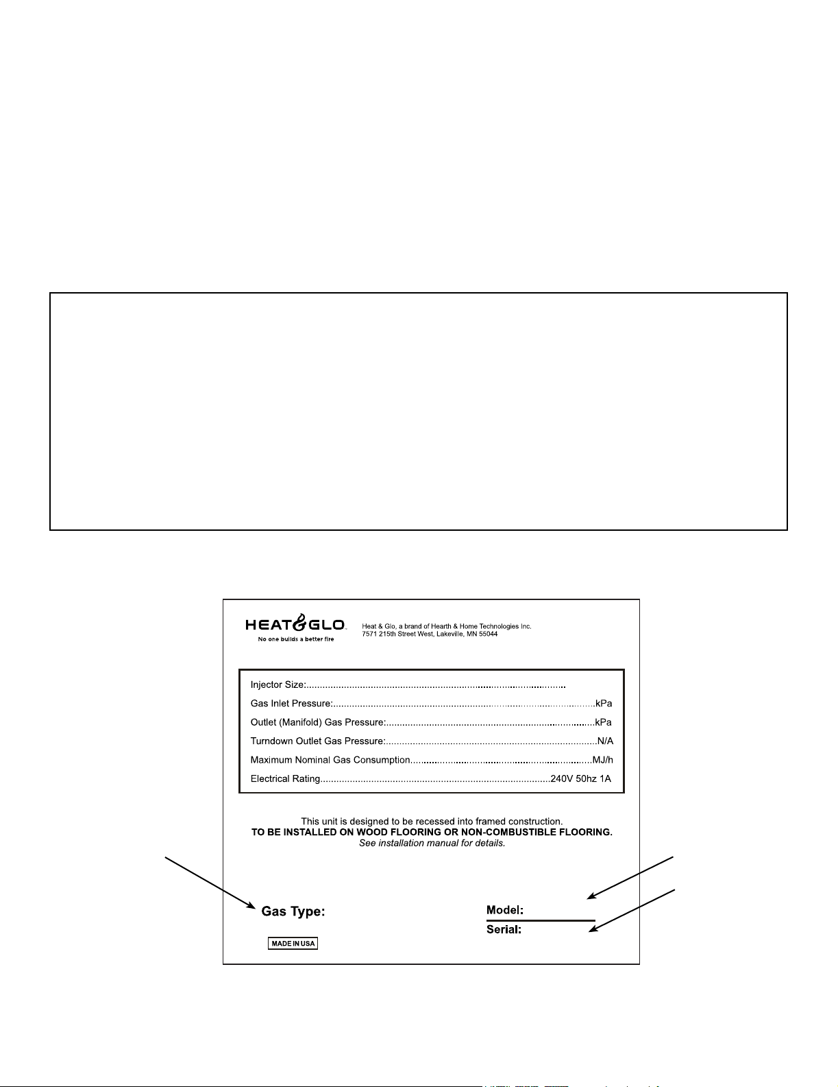
Listing Label Information/Location
The model information regarding your specic replace can be found on
the rating plate usually located in the control area of the replace.
SAI Global Certification Nº:
DMS (mm)
SAMPLE
Model NumberType of Gas
Serial Number
xxxx-xxx
Heat & Glo • VRT-AUB • 2123-980 Rev. J • 2/13
3
Page 4

Safety Alert Key:
• DANGER! Indicates a hazardous situation which, if not avoided will result in death or serious injury.
• WARNING! Indicates a hazardous situation which, if not avoided could result in death or serious injury.
• CAUTION! Indicates a hazardous situation which, if not avoided, could result in minor or moderate injury.
• NOTICE: Used to address practices not related to personal injury.
Table of Contents
A. Congratulations . . . . . . . . . . . . . . . . . . . . . . . . . . . . . . . . . 3
B. Limited Lifetime Warranty . . . . . . . . . . . . . . . . . . . . . . . . . . 6
1 Listing and Code Approvals
A. Appliance Certication . . . . . . . . . . . . . . . . . . . . . . . . . . . . 9
B. Additional Related Standards . . . . . . . . . . . . . . . . . . . . . . . 9
C. Gas Pressure Requirements . . . . . . . . . . . . . . . . . . . . . . . 9
D. High Altitude Installations . . . . . . . . . . . . . . . . . . . . . . . . . . 9
E. Non-Combustible Materials Specication. . . . . . . . . . . . . . 9
F. Combustible Materials Specication . . . . . . . . . . . . . . . . . 9
G. Electrical Codes . . . . . . . . . . . . . . . . . . . . . . . . . . . . . . . . . 9
User Guide
2 Operating Instructions
A. Gas Fireplace Safety . . . . . . . . . . . . . . . . . . . . . . . . . . . . 10
B. Your Fireplace . . . . . . . . . . . . . . . . . . . . . . . . . . . . . . . . . 10
C. Clear Space . . . . . . . . . . . . . . . . . . . . . . . . . . . . . . . . . . . 10
D. Decorative Doors and Fronts . . . . . . . . . . . . . . . . . . . . . . 10
E. Fixed Glass Assembly . . . . . . . . . . . . . . . . . . . . . . . . . . . 10
F. Remote Controls, Wall Controls and Wall Switches . . . . . 10
G. Before Lighting Fireplace . . . . . . . . . . . . . . . . . . . . . . . . . 10
H. Lighting Instructions (IPI) . . . . . . . . . . . . . . . . . . . . . . . . . 11
I. Control Module Operation . . . . . . . . . . . . . . . . . . . . . . . . 12
J. After Fireplace is Lit . . . . . . . . . . . . . . . . . . . . . . . . . . . . . 13
K. Frequently Asked Questions . . . . . . . . . . . . . . . . . . . . . . 13
3 Maintenance and Service
A. Maintenance Tasks-Homeowner . . . . . . . . . . . . . . . . . . . 14
B. Maintenance Tasks-Qualied Service Technician . . . . . . 15
Installer Guide
4 Getting Started
A. Typical Appliance System. . . . . . . . . . . . . . . . . . . . . . . . . 17
B. Design and Installation Considerations . . . . . . . . . . . . . . 18
C. Tools and Supplies Needed . . . . . . . . . . . . . . . . . . . . . . . 18
D. Inspect Appliance and Components . . . . . . . . . . . . . . . . . 18
5 Framing and Clearances
A. Selecting Appliance Location . . . . . . . . . . . . . . . . . . . . . . 19
B. Optional Stone Surround Installed . . . . . . . . . . . . . . . . . . 20
6 Termination Locations
A. Vent Termination Minimum Clearances . . . . . . . . . . . . . . 21
7 Flue Information
A. Flue Components . . . . . . . . . . . . . . . . . . . . . . . . . . . . . . . 23
B. Use of Elbows . . . . . . . . . . . . . . . . . . . . . . . . . . . . . . . . . 23
C. Measuring Standards . . . . . . . . . . . . . . . . . . . . . . . . . . . . 23
D. Flueing Diagrams . . . . . . . . . . . . . . . . . . . . . . . . . . . . . . . 24
E. Flue Pipe Assembly . . . . . . . . . . . . . . . . . . . . . . . . . . . . . 31
F. Horizontal Penetration Framing . . . . . . . . . . . . . . . . . . . . 31
G. Slim Line Wall Thimble . . . . . . . . . . . . . . . . . . . . . . . . . . . 33
H. Vertical Termination . . . . . . . . . . . . . . . . . . . . . . . . . . . . . 34
I. Vertical Flue Restrictor . . . . . . . . . . . . . . . . . . . . . . . . . . . 36
8 Vent Clearances and Framing
A. Pipe Clearances to Combustibles . . . . . . . . . . . . . . . . . . 37
B. Wall Penetration Framing . . . . . . . . . . . . . . . . . . . . . . . . . 37
C. Install the Ceiling Firestop . . . . . . . . . . . . . . . . . . . . . . . . 38
D. Install Attic Insulation Shield . . . . . . . . . . . . . . . . . . . . . . . 39
9 Appliance Setup
A. Remove Shipping Materials . . . . . . . . . . . . . . . . . . . . . . . 40
B. Unbolting Appliance from the Pallet . . . . . . . . . . . . . . . . . 40
C. Leveling and Bolting Down the Appliance . . . . . . . . . . . . 40
D. Accessories . . . . . . . . . . . . . . . . . . . . . . . . . . . . . . . . . . . 41
E. Top to Rear Flue Conversion . . . . . . . . . . . . . . . . . . . . . . 41
F. Installing the Bafe . . . . . . . . . . . . . . . . . . . . . . . . . . . . . . 42
G. Positioning the Logs . . . . . . . . . . . . . . . . . . . . . . . . . . . . . 43
H. Placing Mineral Wool . . . . . . . . . . . . . . . . . . . . . . . . . . . . 43
I. Front Door Glass Assembly Installation . . . . . . . . . . . . . . 44
J. Inner Glass Door Assembly Replacement . . . . . . . . . . . . 44
K. Covers Removal For Servicing. . . . . . . . . . . . . . . . . . . . . 45
L. Components Removal For Service . . . . . . . . . . . . . . . . . 45
M. Parts Replacement . . . . . . . . . . . . . . . . . . . . . . . . . . . . . 45
N. Adjustments And Replacement Parts . . . . . . . . . . . . . . . . 45
O. Install Trim and/or Surround . . . . . . . . . . . . . . . . . . . . . . . 45
P. Air Shutter Setting . . . . . . . . . . . . . . . . . . . . . . . . . . . . . . 45
10 Installing Vent Pipe (SLP Pipe)
A. Assemble Vent Sections. . . . . . . . . . . . . . . . . . . . . . . . . . 46
B. Assemble Slip Sections . . . . . . . . . . . . . . . . . . . . . . . . . . 47
C. Secure The Vent Sections . . . . . . . . . . . . . . . . . . . . . . . . 47
D. Disassemble Vent Sections . . . . . . . . . . . . . . . . . . . . . . . 48
E. Install Decorative Ceiling Components . . . . . . . . . . . . . . 48
F. Install Support Brackets . . . . . . . . . . . . . . . . . . . . . . . . . . 49
G. Install Firestops . . . . . . . . . . . . . . . . . . . . . . . . . . . . . . . . 49
H. Flue Termination . . . . . . . . . . . . . . . . . . . . . . . . . . . . . . . . 50
I. Heat Shield Requirements for Horizontal Termination . . . 51
J. Install Metal Roof Flashing . . . . . . . . . . . . . . . . . . . . . . . . 51
K. Assemble and Install Storm Collar . . . . . . . . . . . . . . . . . . 52
L. Install Vertical Termination Cap . . . . . . . . . . . . . . . . . . . . 52
4
Heat & Glo • VRT-AUB • 2123-980 Rev. J • 2/13
Page 5

11 Gas Information
A. Gas Pressure Requirements . . . . . . . . . . . . . . . . . . . . . . 53
B. Gas Connection . . . . . . . . . . . . . . . . . . . . . . . . . . . . . . . . 53
12 Electrical Information
A. Wiring Requirements . . . . . . . . . . . . . . . . . . . . . . . . . . . . 55
B. IntelliFire PlusTM Ignition System Wiring . . . . . . . . . . . . . . 55
C. Optional Accessories Requirements . . . . . . . . . . . . . . . . 56
D. Blower . . . . . . . . . . . . . . . . . . . . . . . . . . . . . . . . . . . . . . . 56
E. Control Module Operation . . . . . . . . . . . . . . . . . . . . . . . . 57
13 Troubleshooting
A. IntelliFire Plus™Ignition System . . . . . . . . . . . . . . . . . . . 65
14 Reference Materials
A. Appliance Dimension Diagram . . . . . . . . . . . . . . . . . . . . . 67
B. Appliance Dimension with Stone Surround Diagram . . . . 68
C. Maintenance Tasks . . . . . . . . . . . . . . . . . . . . . . . . . . . . . 69
D. Vent Components Diagrams . . . . . . . . . . . . . . . . . . . . . . 70
E. Service Parts . . . . . . . . . . . . . . . . . . . . . . . . . . . . . . . . . . 72
E. Contact Information . . . . . . . . . . . . . . . . . . . . . . . . . . . . . 76
= Contains updated information.
Heat & Glo • VRT-AUB • 2123-980 Rev. J • 2/13
5
Page 6
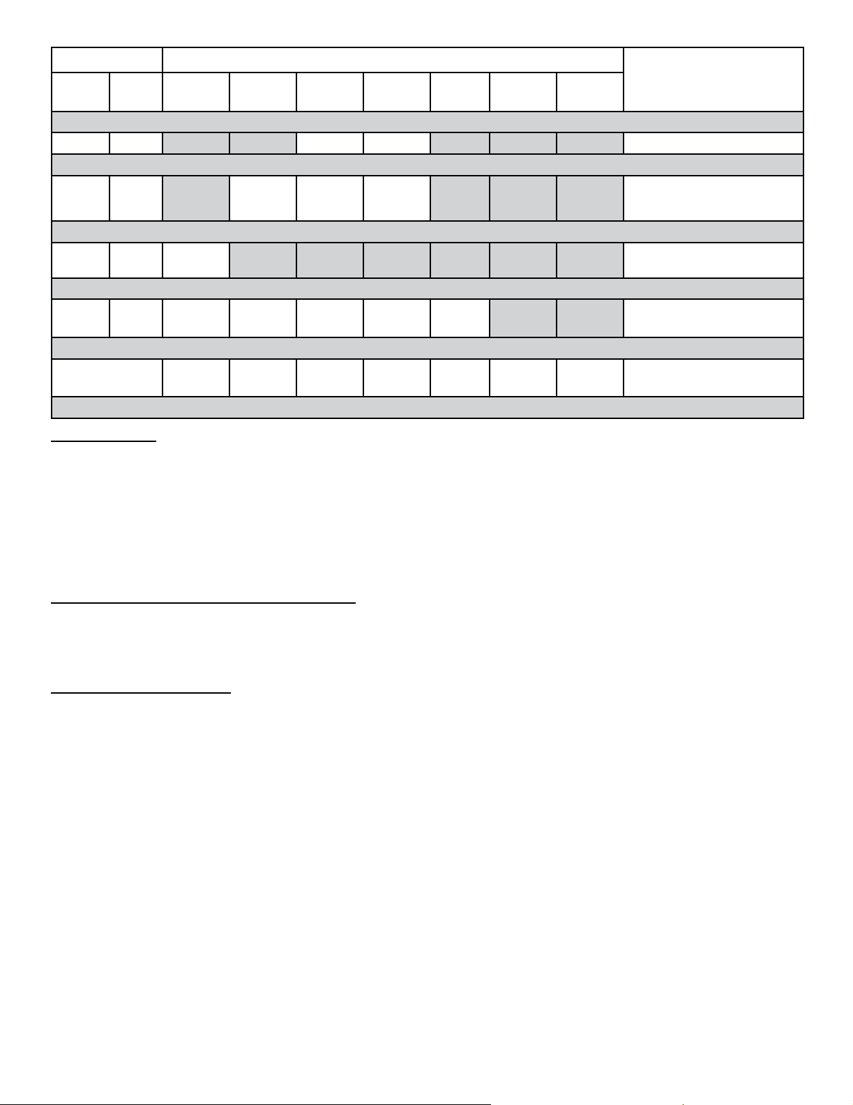
B. Limited Lifetime Warranty
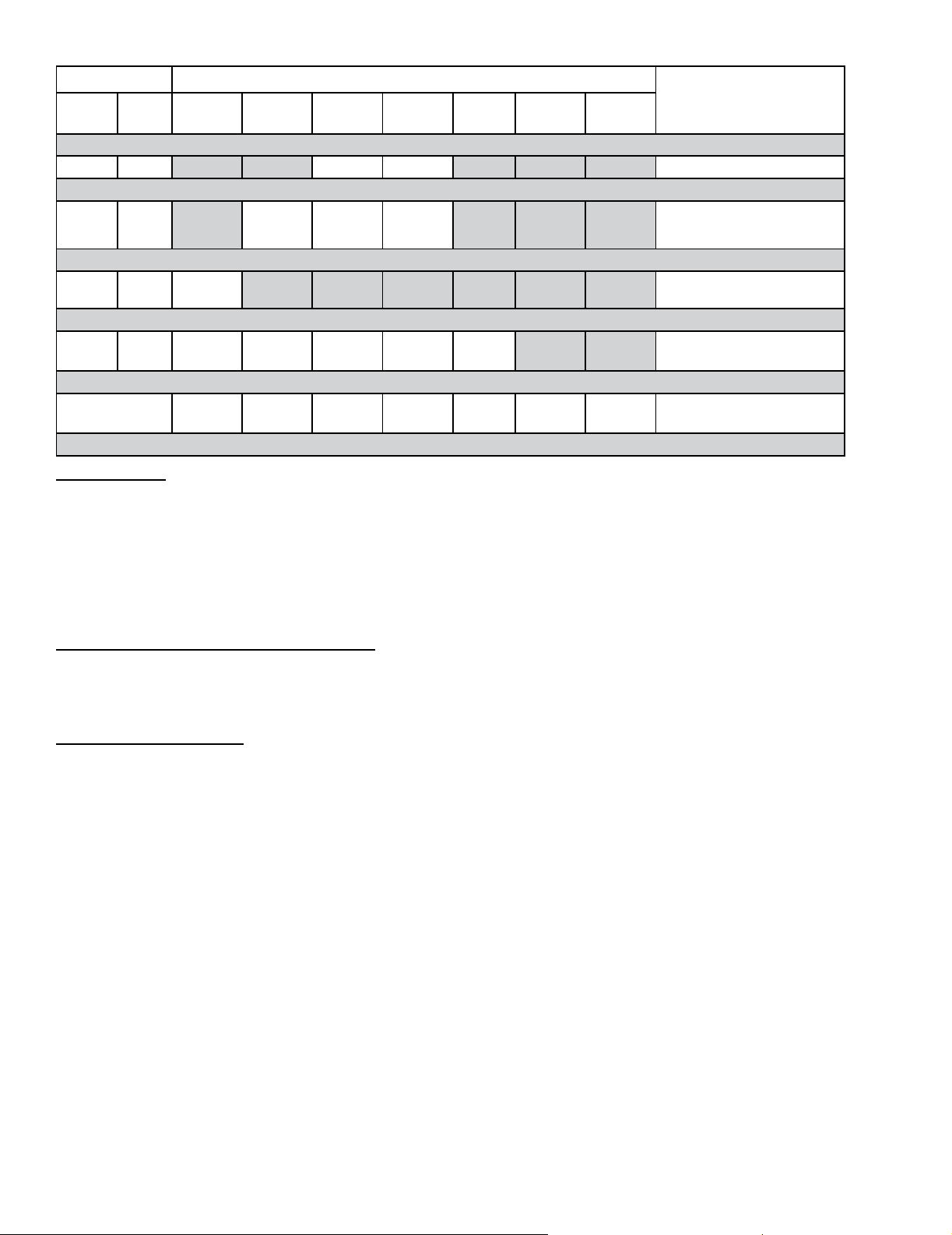
Warranty Period Heat & Glo Manufactured Appliances and Venting
Parts Labor Gas Wood Pellet
5 years 1 years X X Castings & baf es
EPA
Wood
Coal Electric Venting
Components Covered
7 years 3 years X X X
Manifold tubs HEAT & GLO
chimney and termination
10 years 1 year X Burners, logs and refractory
Limited
Lifetime
3 year X X X X X Firebox and heat exchanger
90 Days X X X X X X X
All Replacement Parts
beyond warranty period
OTHER RIGHTS
The HHT manufacturer’s warranty is in addition to other rights and remedies that you may have under Australian
law.
Our goods come with guarantees that cannot be excluded under the Australian Consumer Law. You are entitled
to a replacement or refund for a major failure and for compensation for any other reasonably foreseeable loss or
damage. You are also entitled to have the goods repaired or replaced if the goods fail to be of acceptable quality
and the failure does not amount to a major failure.
WARRANTY CONDITIONS AND EXCLUSIONS:
• The HHT manufacturer’s warranty only covers HHT appliances that are purchased through an HHT authorized dealer
or distributor. A list of HHT authorized dealers is available on the HHT branded websites.
• This warranty is only valid while the HHT appliance remains at the site of original installation.
WARRANTY EXCLUSIONS:
This HHT manufacturer’s warranty does not cover the following:
• Changes in surface nishes as a result of normal use. As a heating appliance, some changes in color of interior and
exterior surface nishes may occur. This is not a aw and is not covered under warranty.
• Damage to printed, plated, or enamelled surfaces caused by ngerprints, accidents, misuse, scratches, melted items,
or other external sources and residues left on the plated surfaces from the use of abrasive cleaners or polishes.
• Repair or replacement of parts that are subject to normal wear and tear during the warranty period. These parts include: paint, wood, pellet and coal gaskets, rebricks, grates, ame guides, light bulbs, batteries and the discoloration
of glass.
• Minor expansion, contraction, or movement of certain parts causing noise. These conditions are normal and complaints related to this noise are not covered by this warranty.
• Damages resulting from: (1) failure to install, operate, or maintain the appliance in accordance with the installation
instructions, operating instructions, and listing agent identi cation label furnished with the appliance; (2) failure to install the appliance in accordance with local building codes; (3) shipping or improper handling; (4) improper operation,
abuse, misuse, continued operation with damaged, corroded or failed components, accident, or improperly/incorrectly
performed repairs; (5) environmental conditions, inadequate ventilation, negative pressure, or drafting caused by
tightly sealed constructions, insuf cient make-up air supply, or handling devices such as exhaust fans or forced air furnaces or other such causes; (6) use of fuels other than those speci ed in the operating instructions; (7) installation or
use of components not supplied with the appliance or any other components not expressly authorized and approved
by HHT (8) modi cation of the appliance not expressly authorized and approved by HHT in writing; and/or (9) interruptions or uctuations of electrical power supply to the appliance.
2000-645B (1-13) Page 2 of 3
6
Heat & Glo • VRT-AUB • 2123-980 Rev. J • 2/13
Page 7
Warranty Period Heat & Glo Manufactured Appliances and Venting
Parts Labor Gas Wood Pellet
EPA
Wood
Coal Electric Venting
Components Covered
5 years 1 years X X Castings & baf es
7 years 3 years X X X
Manifold tubs HEAT & GLO
chimney and termination
10 years 1 year X Burners, logs and refractory
Limited
Lifetime
3 year X X X X X Firebox and heat exchanger
90 Days X X X X X X X
All Replacement Parts
beyond warranty period
OTHER RIGHTS
The HHT manufacturer’s warranty is in addition to other rights and remedies that you may have under Australian
law.
Our goods come with guarantees that cannot be excluded under the Australian Consumer Law. You are entitled
to a replacement or refund for a major failure and for compensation for any other reasonably foreseeable loss or
damage. You are also entitled to have the goods repaired or replaced if the goods fail to be of acceptable quality
and the failure does not amount to a major failure.
WARRANTY CONDITIONS AND EXCLUSIONS:
• The HHT manufacturer’s warranty only covers HHT appliances that are purchased through an HHT authorised dealer
or distributor. A list of HHT authorised dealers is available on the HHT branded websites.
• This warranty is only valid while the HHT appliance remains at the site of original installation.
WARRANTY EXCLUSIONS:
This HHT manufacturer’s warranty does not cover the following:
• Changes in surface nishes as a result of normal use. As a heating appliance, some changes in color of interior and
exterior surface nishes may occur. This is not a aw and is not covered under warranty.
• Damage to printed, plated, or enamelled surfaces caused by ngerprints, accidents, misuse, scratches, melted items,
or other external sources and residues left on the plated surfaces from the use of abrasive cleaners or polishes.
• Repair or replacement of parts that are subject to normal wear and tear during the warranty period. These parts in-
clude: paint, wood, pellet and coal gaskets, rebricks, grates, ame guides, light bulbs, batteries and the discoloration
of glass.
• Minor expansion, contraction, or movement of certain parts causing noise. These conditions are normal and com-
plaints related to this noise are not covered by this warranty.
• Damages resulting from: (1) failure to install, operate, or maintain the appliance in accordance with the installation
instructions, operating instructions, and listing agent identi cation label furnished with the appliance; (2) failure to install the appliance in accordance with local building codes; (3) shipping or improper handling; (4) improper operation,
abuse, misuse, continued operation with damaged, corroded or failed components, accident, or improperly/incorrectly
performed repairs; (5) environmental conditions, inadequate ventilation, negative pressure, or drafting caused by
tightly sealed constructions, insuf cient make-up air supply, or handling devices such as exhaust fans or forced air furnaces or other such causes; (6) use of fuels other than those speci ed in the operating instructions; (7) installation or
use of components not supplied with the appliance or any other components not expressly authorized and approved
by HHT (8) modi cation of the appliance not expressly authorized and approved by HHT in writing; and/or (9) interruptions or uctuations of electrical power supply to the appliance.
2000-645 (1-12) Page 2 of 3
Heat & Glo • VRT-AUB • 2123-980 Rev. J • 2/13
7
Page 8

• Non Heat & Glo venting components, hearth components or other accessories used in conjunction with the appliance.
• Any part of a pre-existing replace system in which an insert or a decorative gas appliance is installed.
• Removal, installation, reinstallation, set up or any other costs associated with a claim including travel and shipping
charges for parts
• HHT’s obligation under this warranty does not extend to the appliance’s capability to heat the desired space. Informa-
tion is provided to assist the consumer and the dealer in selecting the proper appliance for the application. Consideration must be given to appliance location and con guration, environmental conditions, insulation and air tightness of
the structure.
This warranty is void if:
• The appliance has been over- red or operated in atmospheres contaminated by chlorine, uorine, or other damaging
chemicals. Over- ring can be identi ed by, but not limited to, warped plates or tubes, rust colored cast iron, bubbling,
cracking and discoloration of steel or enamel nishes.
• The appliance is subjected to prolonged periods of dampness or condensation.
There is any damage to the appliance or other components due to water or weather damage which is the result of, but not
limited to, improper chimney or venting installation.
HOW TO CLAIM
• To make a claim against this warranty, contact your local distributor during regular business hours. See addresses
below for a dealer nearest you. (Vic) Pty Ltd ACN 005 872 159 (Jetmaster).
• Additional service fees may apply if you are seeking warranty service from a dealer other than the dealer from whom
you originally purchased the product.
• Check with Jetmaster in advance for any costs to you when arranging a warranty call. Travel and shipping charges for
parts are not covered by this manufacturers’ warranty.
• HHT and Jetmaster will assess your claim. HHT or Jetmaster may need to inspect the product as part of the assess-
ment of your claim. If the product requires inspection, HHT or Jetmaster will discuss with you the best way for this to
occur.
• To make a claim under this manufacturer’s warranty, you must be able to prove when you purchased the product. The
easiest way to do this is through your original proof of purchase, for example your invoice or receipt. However, if you
do not have your original proof of purchase HHT or Jetmaster may accept other evidence of the date of purchase.
Melbourne
Jetmaster
444 Swan Street
Richmond 3121
(03) 9429-5573
Perth
Fireplace Corner
277 Lord Street
East Perth 6000
(08) 9228-2600
Sydney
Jetmaster
10 Martin Avenue
Arncliff 2205
(02) 9597-7222
2000-645 (1-12) Page 3 of 3
8
Heat & Glo • VRT-AUB • 2123-980 Rev. J • 2/13
Page 9
1
Listing and Code Approvals
A. Appliance Certication
MODELS: VRT-AUB
LABORATORY: SAI Global
TYPE: Gas Space Heating Appliance
STANDARD: AS4553:2008
B. Additional Related Standards
The installation must comply with these installation instructions and all relevant parts of Local and National Building
Standards Regulations and those relevant recommendations of the following British Standards. BS 5871: Part 1
BS 8303 BS 5440: Parts 1 & 2 BS 6891 BSEN1856 Parts
1 & 2 BS 5482 Part 1, as well as IGE/UP/7.
The Heat & Glo gas appliances discussed in this Installer’s
Guide have been tested to certication standards and listed
by the applicable laboratories.
This appliance must be installed in accordance with the
rules in force.
NOX Class 5 for G20, NOX Class 5 for G31
C. Gas Pressure Requirements
Pressure requirements for VRT-AUB replaces are shown
in table below.
Two taps are provided on the right hand side of the gas
control for a test gauge connection to measure the inlet
and outlet pressures.
Natural Gas Propane
Inlet Gas Pressure 1.13 - 3.40 kPa 2.75 - 3.40 kPa
Outlet (Manifold) Gas
Pressure
Max. Gas Consumption 26.7 mJ 24.5 mJ
.80 - .95 kPa 2.36 - 2.61 kPa
The replace and its individual shut-off valve must be disconnected from the gas supply piping system during any
pressure testing of the system at test pressures in excess
of 6 kPa.
If the replace must be isolated from the gas supply piping system by closing an individual shut-off valve, it must
be of the handle-less type.
WARNING! Risk of Explosion! An in-line regulator
MUST be installed if the gas pressure exceeds 3.7 kPa.
Failure to install a regulator could damage valve.
D. High Altitude Installations
NOTICE: If the heating value of the gas has been reduced,
these rules do not apply. Check with your local gas utility
or authorities having jurisdiction.
When installing above 610 meter elevation:
Reduce input rate 4% for each 305 meters feet above
610 meters.
E. Non-Combustible Materials Specication
Material which will not ignite and burn. Such materials are
those consisting entirely of steel, iron, brick, tile, concrete,
slate, glass or plasters, or any combination thereof.
Materials that are reported as passing ASTM E 136,
Standard Test Method for Behavior of Materials in a
Vertical Tube Furnace at 750 ºC (1832 ºF) and UL763
shall be considered non-combustible materials.
F. Combustible Materials Specication
Materials made of or surfaced with wood, compressed paper, plant bers, plastics, or other material that can ignite
and burn, whether ame proofed or not, or plastered or
unplastered shall be considered combustible materials.
G. Electrical Codes
All electrical safety testing has been done following the EN
60335-2-102 standard. Local codes apply.
Burner Injector 2.53 mm 1.45 mm
Burner Air Shutter 13 mm 11.5 mm
An in-line regulator MUST be installed if the gas pressure
exceeds 3.40 kPa. Failure to install a regulator could
damage valve.
Heat & Glo • VRT-AUB • 2123-980 Rev. J • 2/13
9
Page 10
2
Operating Instructions
User Guide
A. Gas Fireplace Safety
WARNING
HOT SURFACES!
Glass and other surfaces are hot during
operation AND cool down.
Hot glass will cause burns.
• DO NOT touch glass until it is cooled
• NEVER allow children to touch glass
• Keep children away
• CAREFULLY SUPERVISE children in same room as
replace.
• Alert children and adults to hazards of high temperatures.
Hi gh temp eratures may ignite cloth ing or othe r
ammable materials.
• Keep clothing, furniture, draperies and other ammable
materials away.
This appliance has been supplied with an integral barrier
to prevent direct contact with the xed glass panel. DO
NOT operate the appliance with the barrier removed.
Contact your dealer or Hearth & Home Technologies if the
barrier is not present or help is needed to properly install one.
This appliance is not intended for use by persons (including
children) with reduced physical, sensory or mental capabilities, or lack of experience and knowledge, unless they
have been given supervision or instruction concerning use
of the appliance by a person responsible for their safety.
Children should be supervised to ensure that they do not
play with the appliance.
If you expect that small children or vulnerable adults may
come into contact with this replace, the following precautions are recommended:
• Install a physical barrier such as:
- A decorative rescreen.
- Adjustable safety gate.
• Install a switch lock or a wall/remote control with child
protection lockout feature.
• Keep remote controls out of reach of children.
• Never leave children alone near a hot replace, whether
operating or cooling down.
• Teach children to NEVER touch the replace.
• Consider not using the replace when children will be
present.
To prevent unintended operation when not using your replace for an extended period of time (summer months,
vacations, trips, etc):
• Remove batteries from remote controls.
• Turn off wall controls.
• Unplug 6 volt adapter plug and remove batteries on IPI
models.
B. Your Fireplace
WARNING! DO NOT operate replace before reading and understanding operating instructions. Failure
to operate replace according to operating instructions
could cause re or injury.
C. Clear Space
WARNING! DO NOT place combustible objects in front
of the replace or block louvers. High temperatures may
start a re.
Avoid placing candles and other heat-sensitive objects on
mantel or hearth. Heat may damage these objects.
D. Decorative Doors and Fronts
WARNING! Risk of Fire! Install ONLY doors or fronts
approved by Hearth & Home Technologies. Unapproved
doors or fronts may cause replace to overheat.
This fireplace has been supplied with an integral
barrier to prevent direct contact with the xed glass
panel. DO NOT operate the replace with the barrier
removed.
Contact your dealer or Hearth & Home Technologies if
the barrier is not present or help is needed to properly
install one.
For more information refer to the instructions supplied with
your decorative door or front.
E. Fixed Glass Assembly
See Sections 9.I through 9.K.
F. Remote Controls, Wall Controls and Wall
Switches
Follow the instructions supplied with the control installed
to operate your replace:
For safety:
• Install a switch lock or a wall/remote control with child
protection lockout feature.
• Keep remote controls out of reach of children.
See your dealer if you have questions.
G. Before Lighting Fireplace
Before operating this replace for the rst time, have a
qualied service technician:
• Verify all shipping materials have been removed from
inside and/or underneath the rebox.
• Review proper placement of logs, ember material and/
or other decorative materials.
• Check the wiring.
• Check the air shutter adjustment.
• Ensure that there are no gas leaks.
• Ensure that the glass is sealed and in the proper position
and that the integral barrier is in place.
WARNING! Risk of Fire or Asphyxiation! DO NOT op-
erate replace with xed glass assembly removed.
10
Heat & Glo • VRT-AUB • 2123-980 Rev. J • 2/13
Page 11
H. Lighting Instructions (IPI)
FOR YOUR SAFETY
READ BEFORE LIGHTING
WARNING: If you do not follow these instructions exactly, a re or explosion
may result causing property damage, personal injury or loss of life.
A. This appliance is equipped with an
intermittent pilot ignition (IPI) device
which automatically lights the burner. DO NOT try to light the burner by
hand.
B. BEFORE LIGHTING, smell all around
the appliance area for gas. Be sure to
smell next to the oor because some
gas is heavier than air and will settle
on the oor.
WHAT TO DO IF YOU SMELL GAS
• DO NOT try to light any appliance.
• DO NOT touch any electric switch; do
not use any phone in your building.
WARNING:
DO NOT CONNECT LINE VOLTAGE (110/120 VAC OR 220/240
VAC) TO THE CONTROL VALVE.
Improper installation, adjustment, alteration, service or maintenance can
cause injury or property damage. Refer to the owner’s information manual
provided with this appliance.
This appliance needs fresh air for
safe operation and must be installed
so there are provisions for adequate
combustion and ventilation air.
If not installed, operated, and maintained in accordance with the manufacturer’s instructions, this product could
expose you to substances in fuel or
fuel combustion which are known to the
State of California to cause cancer, birth
defects, or other reproductive harm.
Keep burner and control compartment
clean. See installation and operating
instructions accompanying appliance.
• Immediately call your gas supplier
from a neighbor’s phone. Follow the
gas supplier’s instructions.
• If you cannot reach your gas supplier, call the re department.
C. DO NOT use this appliance if any
part has been under water. Immediately call a qualied service technician to inspect the appliance and
to replace any part of the control
system and any gas control which
has been under water.
CAUTION:
Hot while in operation. DO NOT touch.
Keep children, clothing, furniture, gasoline and other liquids having ammable
vapors away.
DO NOT operate the appliance with
xed glass assembly removed, cracked
or broken. Replacement of the xed
glass assembly should be done by a
licensed or qualied service person.
NOT FOR USE
WITH SOLID FUEL
For use with natural gas and propane.
A conversion kit, as supplied by the
manufacturer, shall be used to convert
this appliance to the alternate fuel.
Also Certied for Installation in a
Bedroom or a Bedsitting Room.
For assistance or additional information, consult a qualied installer, service agency or the gas supplier.
LIGHTING
INSTRUCTIONS (IPI)
1. This appliance is equipped with an ignition
device which automatically lights the burner.
DO NOT try to light the burner by hand.
GAS
VALVE
2. Wait ve (5) minutes to clear out any gas.
Then smell for gas, including near the oor. If
you smell gas, STOP! Follow “B” in the Safety
Information located on the left side of this label. If you do not smell gas, go to next step.
3. To light the burner:
Equipped with wall switch: Turn ON/OFF switch
to ON.
Equipped with remote or wall control: Press
ON or FLAME button.
Equipped with thermostat: Set temperature to
desired setting.
4. If the appliance does not light after three tries,
call your service technician or gas supplier.
TO TURN OFF
GAS TO APPLIANCE
1. Equipped with wall switch: Turn ON/OFF switch
to OFF.
Equipped with remote or wall control: Press
OFF button.
Equipped with thermostat: Set temperature to
lowest setting.
2. Service technician should turn off electric
power to the control when performing service.
593-913G
Hearth & Home Technologies replace, please refer to www.replaces.com.
For additional information on operating your
Final inspection by
Heat & Glo • VRT-AUB • 2123-980 Rev. J • 2/13
11
Page 12
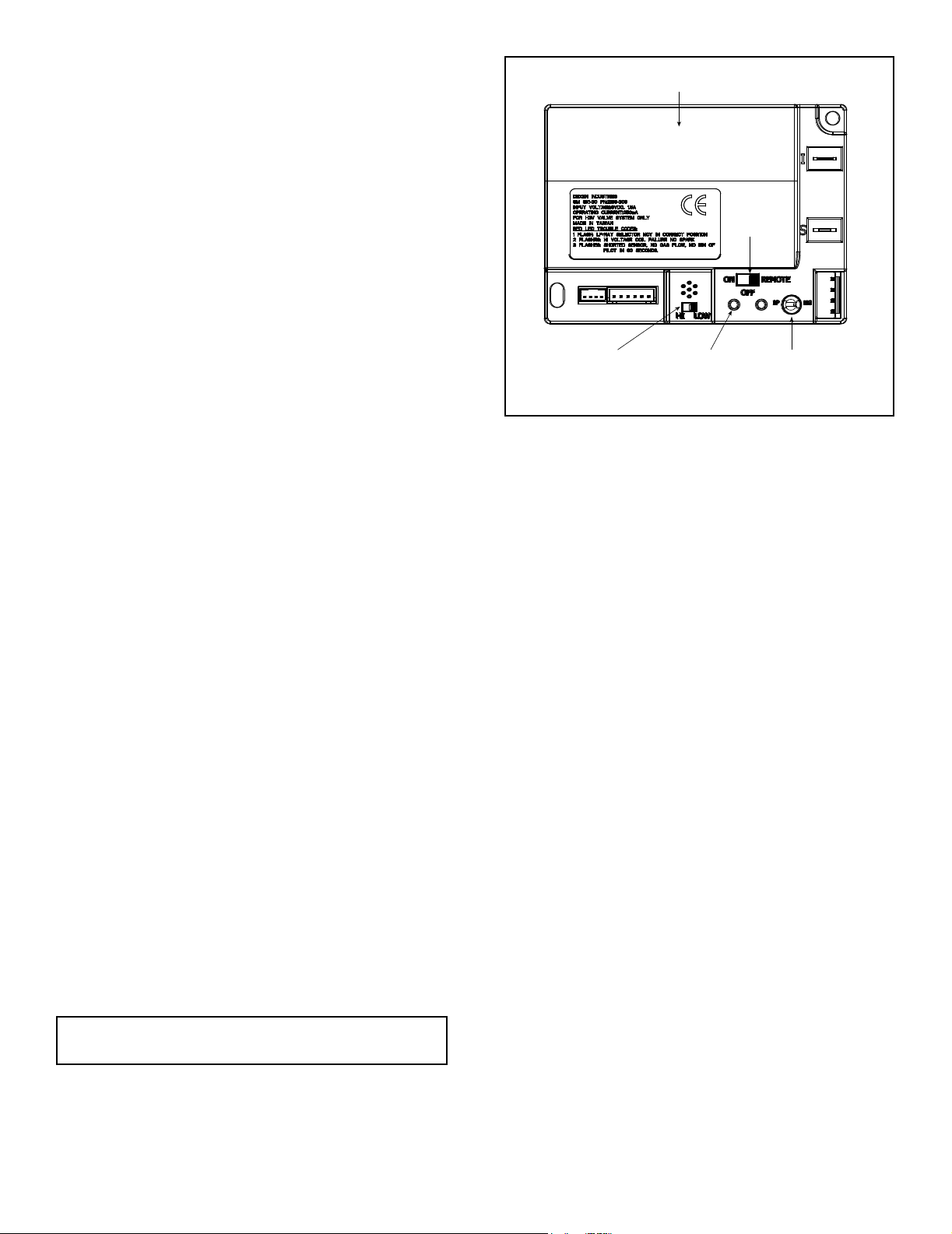
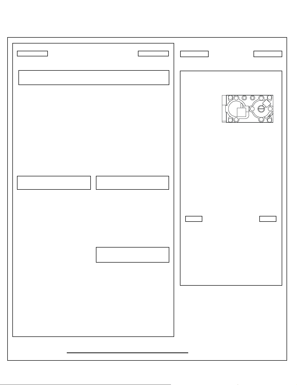
I. Control Module Operation
1. The control module has an ON/OFF/REMOTE selector
switch that must be set. See Figure 2.1.
OFF Position: Appliance will ignore all power inputs and
will not respond to any commands from a wall switch or
remote. The unit should be in the OFF position during
installation, service, battery installation, fuel conversion,
and in the event that the control goes into LOCK-OUT
mode as a result of an error code.
ON Position: Appliance will ignite and run continuously
in the HI ame setting, with no adjustment in ame
output. This mode of operation is primarily used for
initial installation or power outage operation with battery
backup.
REMOTE Position: Appliance will initiate commands
from an optional wired wall switch and/or the wireless
remote (RC300AU).
2. If using a wired wall switch with the module in REMOTE
mode, the ame output can be adjusted with the HI/
LO selector switch on the module. See Figure 2.3.
Note that the ame HI/LO selector switch will become
inactive once an optional remote control (RC300AU) is
programmed to the control module. Note that the control
module will always ignite the replace on HI and remain
so for the initial 10 seconds of operation. If the HI/LO
is switched to the LO position, the ame output will
automatically drop to the lowest setting after the ame
has been established for 10 sec. After this 10 second
period, the ame can be adjusted from HI to LO with
the switch.
3. The control module has safety feature that automatically
shuts down the replace after 9 hours of continuous
operation without receiving a command from the
RC300AU remote.
4. If you intend to use both an optional wired wall switch
and the RC300AU remote control to operate your
replace, the wall switch will override any commands
given by the remote.
5. The module has the capability to recognize potential
malfunctions. If these occur, it will fail to ignite and/
or respond to a command to ignite via the wall switch
and/or remote. In this case, the module may have
gone into LOCK-OUT mode. In this state, it will emit
a LED error code. To reset the error code, switch the
selector to OFF, and then back to REMOTE or ON. If
the ignition command again fails, the module will emit
an LED error code, prior to going back into LOCK-OUT
mode. Contact your dealer for service if this occurs.
MODULE
FLAME HI/LOW
SWITCH
Figure 2.1 Control Module
INDICATOR LED
STATUS
SELECTOR
SWITCH
NG/LP GAS-TYPE
SELECTOR SWITCH
Note: If the module is in LOCK-OUT mode, resetting the
circuit breaker to the appliance will also reset the module.
12
Heat & Glo • VRT-AUB • 2123-980 Rev. J • 2/13
Page 13
J. After Fireplace is Lit
Initial Break-in Procedure
• The fireplace should be r un t hree to four hours
continuously on high.
• Turn the replace off and allow it to completely cool.
• Remove xed glass assembly. See Section 9.I through 9.K.
• Clean xed glass assembly. See Section 3.
• Replace the xed glass assembly and run continuously
on high an additional 12 hours.
This cures the materials used to manufacture the replace.
NOTICE! Open windows for air circulation during replace break-in.
• Some people may be sensitive to smoke and odors.
• Smoke detectors may activate.
K. Frequently Asked Questions
ISSUE SOLUTIONS
Condensation on the glass
Blue ames
Odor from replace
Film on the glass
Metallic noise
Power Outages (battery backup)
Wall above appliance feels hot to
the touch.
This is a result of gas combustion and temperature variations. As the replace warms, this condensation will disappear.
This is a result of normal operation and the ames will begin to yellow as the replace is allowed
to burn for 20 to 40 minutes.
When rst operated, this replace may release an odor for the rst several hours. This is caused
by the curing of materials from manufacturing. Odor may also be released from nishing materials
and adhesives used near the replace. These circumstances may require additional curing related
to the installation environment.
This is a normal result of the curing process of the paint. Glass should be cleaned within 3 to 4
hours of initial burning. A non-abrasive cleaner such as gas appliance glass cleaner may be necessary. See your dealer.
Noise is caused by metal expanding and contracting as it heats up and cools down, similar to the
sound produced by a furnace or heating duct. This noise does not affect the operation or longevity
of the replace.
This appliance can operated on battery power in the event of a power outage. To access the battery pack, the decorative front, mesh and glass assembly must be removed. Refer to Section 12
for more details.
No action necessary. This appliance ships with a non-combustible material attached. Specications of the attached non-combustible material are listed in Section 1.E.
Heat & Glo • VRT-AUB • 2123-980 Rev. J • 2/13
13
Page 14
3
Maintenance and Service
Any safety screen or guard removed for servicing must be
replaced prior to operating the replace.
When properly maintained, your replace will give you
many years of trouble-free service. We recommend annual service by a qualied service technician.
A. Maintenance Tasks-Homeowner
Installation and repair should be done by a qualied service
technician only. The replace should be inspected before
use and at least annually by a professional service person.
The following tasks may be performed annually by the
homeowner. If you are uncomfortable performing any of
the listed tasks, please call your dealer for a service appointment.
More frequent cleaning may be required due to lint from
carpeting or other factors. Control compartment, burner
and circulating air passageway of the replace must be
kept clean.
CAUTION! Risk of Burns! The replace should be turned
off and cooled before servicing.
Glass Cleaning
Frequency: Seasonally
By: Homeowner
Tools Needed: Protective gloves, glass cleaner, drop
cloth and a stable work surface.
CAUTION! Handle xed glass assembly with care.
Glass is breakable.
• Avoid striking, scratching or slamming glass
• Avoid abrasive cleaners
• DO NOT clean glass while it is hot
• Prepare a work area large enough to accommodate xed
glass assembly and door frame by placing a drop cloth
on a at, stable surface.
Note: Fixed glass assembly and gasketing may have residue that can stain carpeting or oor surfaces.
• Remove door or decorative front from replace and set
aside on work surface.
• See Sections 9.I and 9.K for instructions to remove xed
glass assembly.
• Clean glass with a non-abrasive commercially available
cleaner.
- Light deposits: Use a soft cloth with soap and water
- Heavy deposits: Use commercial fireplace glass
cleaner (consult with your dealer)
• Carefully set xed glass assembly in place on replace.
Hold glass in place with one hand and secure glass
latches with the other hand.
• Reinstall door or decorative front.
Doors, Surrounds, Fronts
Frequency: Annually
By: Homeowner
Tools needed: Protective gloves, stable work surface
• Inspect for scratches, dents or other damage and repair
as necessary.
• Check that louvers are not blocked.
• Vacuum and dust surfaces.
Remote Control
Frequency: Seasonally
By: Homeowner
Tools needed: Replacement batteries and remote con-
trol instructions.
• Locate remote control transmitter and receiver.
• Verify operation of remote. Refer to remote control
operation instructions for proper calibration and setup
procedure.
• Place batteries as needed in remote transmitters and
battery-powered receivers.
• Place remote control out of reach of children.
If not using your replace for an extended period of time
(summer months, vacations/trips, etc), to prevent unintended operation:
• Remove batteries from remote controls.
• Unplug 6 volt adapter plug on IPI models.
• Remove battery backup from control module.
Venting
Frequency: Seasonally
By: Homeowner
Tools needed: Protective gloves and safety glasses.
• Inspect venting and termination cap for blockage or
obstruction such plants, bird nests, leaves, snow, debris,
etc.
• Verify termination cap clearance to subsequent construction (building additions, decks, fences, or sheds). See
Sections 6 through 8.
• Inspect through corrosion or separation.
• Verify weather stripping, sealing and ashing remains
intact.
• Inspect draft shield to verify it is not damaged or missing.
14
Heat & Glo • VRT-AUB • 2123-980 Rev. J • 2/13
Page 15

B. Maintenance Tasks-Qualied Service
Technician
To prevent inadvertent burner operation while servicing
this appliance:
• Unplug DC regulator from junction box.
• Remove batteries from battery pack (if installed).
• Shut off gas supply to the appliance.
The following tasks must be performed by a qualied service technician.
Gasket Seal and Glass Assembly Inspection
Frequency: Annually
By: Qualied Service Technician
Tools needed: Protective gloves, drop cloth and a stable
work surface.
• Inspect gasket seal and its condition.
• Inspect xed glass assembly for scratches and nicks that
can lead to breakage when exposed to heat.
• Conrm there is no damage to glass or glass frame.
Replace as necessary.
• Verify that xed glass assembly is properly retained and
attachment components are intact and not damaged.
Replace as necessary.
Logs
Frequency: Annually
By: Qualied Service Technician
Tools needed: Protective gloves.
• Inspect for damaged or missing logs. Replace as necessary. Refer to Section 9.G for log placement instructions.
• Verify correct log placement and no ame impingement
causing sooting. Correct as necessary.
Firebox
Frequency: Annually
By: Qualied Service Technician
Tools needed: Protective gloves, sandpaper, steel wool,
cloths, mineral spirits, primer and touch-up paint.
• Inspect for paint condition, warped surfaces, corrosion
or perforation. Sand and repaint as necessary.
• Replace replace if rebox has been perforated.
Control Compartment and Firebox Top
Frequency: Annually
By: Qualied Service Technician
Tools needed: Protective gloves, vacuum cleaner, dust
cloths
• Vacuum and wipe out dust, cobwebs, debris or pet hair.
Use caution when cleaning these areas. Screw tips that
have penetrated the sheet metal are sharp and should
be avoided.
• Remove all foreign objects.
• Verify unobstructed air circulation.
Gas Pressure Information
Frequency: Upon initial installation and gas valve re-
placement or service.
By: Qualied Service Technician
Tools needed: Protective gloves, manometer, ashlight,
screw driver set.
• Gas pressure taps are accessible by removing the decorative front and xed glass assembly. Refer to section 11
for information related to the gas valve and gas pressure
settings.
Heat & Glo • VRT-AUB • 2123-980 Rev. J • 2/13
15
Page 16
Burner Ignition and Operation
Frequency: Annually
By: Qualied Service Technician
Tools needed: Protective gloves, vacuum cleaner, whisk
broom, ashlight, voltmeter, indexed drill bit set, and a
manometer.
• Verify burner is properly secured and aligned with pilot
or igniter.
• Clean off burner top, inspect for plugged ports, corrosion
or deterioration. Replace burner if necessary.
• Replace Glowing embers with new dime-size pieces.
DO NOT block ports or obstruct lighting paths.
• Verify batteries have been removed from battery back-up
IPI systems to prevent premature battery failure or
leaking.
• Check for smooth lighting and ignition carryover to all
ports. Verify that there is no ignition delay.
• Inspect for lifting or other ame problems.
• Verify air shutter setting is correct. See Section 9 for
required air shutter setting. Verify air shutter is clear of
dust and debris.
• Inspect orice for soot, dirt and corrosion. Verify orice
size is correct. See Service Parts List for proper orice
sizing.
• Verify manifold and inlet pressures. Adjust regulator as
required.
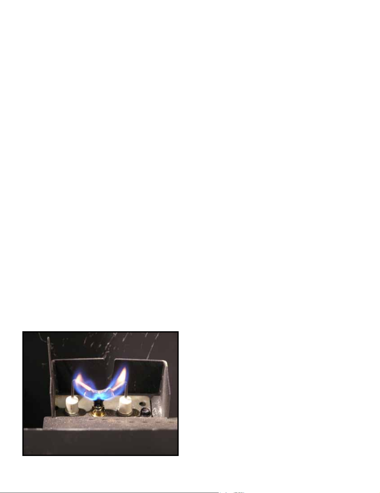
• Inspect pilot ame pattern and strength. See Figure 3.1
for proper pilot ame pattern. Clean or replace orice
spud as necessary.
• Inspect IPI ame sensing rod for soot, corrosion and
deterioration. Polish with ne steel wool or replace as
required.
• Verify that there is not a short in ame sense circuit
by checking continuity between pilot hood and ame
sensing rod. Replace pilot as necessary.
Figure 3.1 IPI Pilot Flame Patterns
16
Heat & Glo • VRT-AUB • 2123-980 Rev. J • 2/13
Page 17
4
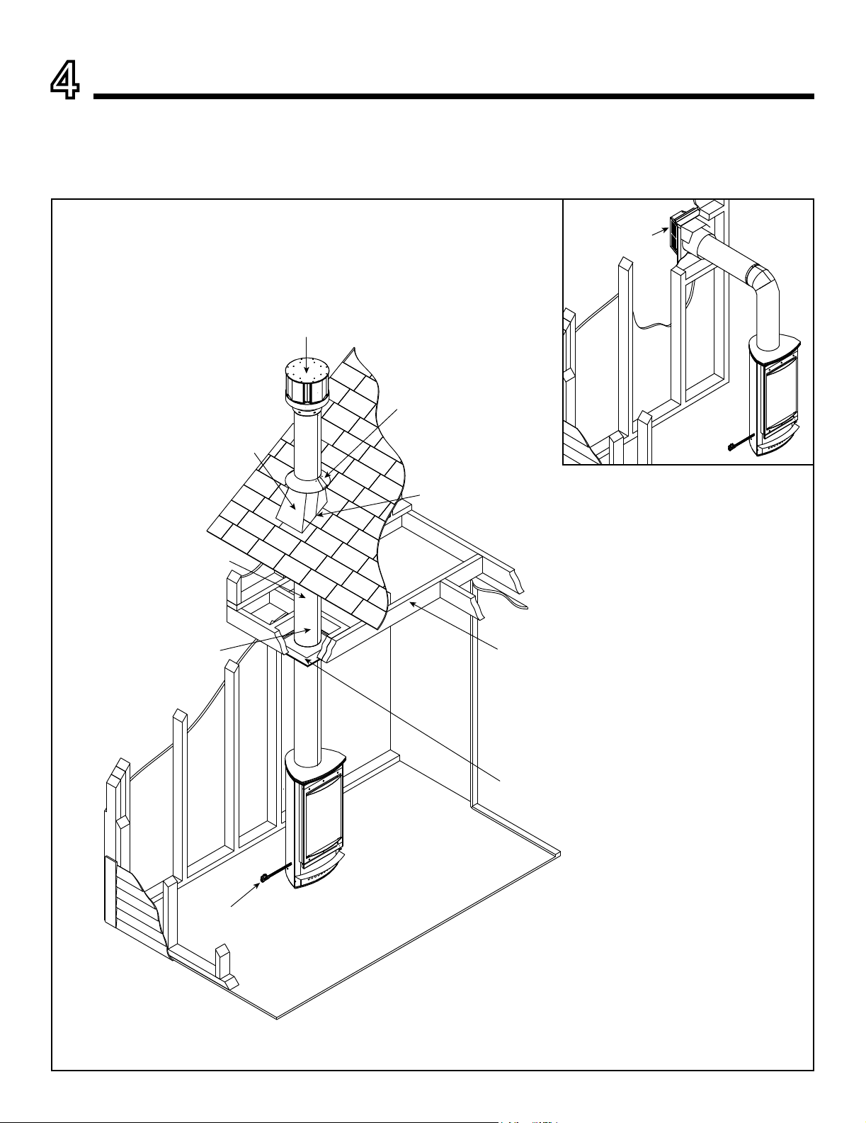
HORIZONTAL
TERMINATION CAP
(SECTION 10.H)
A. Typical Appliance System
NOTICE: Illustrations and photos reect typical installations and are for design purposes only. Illustrations/diagrams are not
drawn to scale. Actual product may vary from pictures in manual
Getting Started
VERTICAL TERMINATION CAP
(SECTION 10.L)
STORM COLLAR
(SECTION 10.K)
NON-COMBUSTIBLE ROOF FLASHING
MAINTAINS MINIMUM CLEARANCE AROUND
PIPE (SECTION 10.J)
VENT PIPE PENETRATES ROOF
PREFERABLY WITHOUT AFFECTING
ROOF RAFTERS (SECTION 8)
Installer Guide
VENT PIPE (SECTIONS 7 & 8)
ATTIC INSULATION SHIELD (NOT SHOWN)
MUST BE USED HERE TO KEEP
INSULATION AWAY FROM VENT PIPE IF
ATTIC IS INSULATED (SECTION 8.D)
GAS LINE
(SECTION 11)
FRAMING HEADED OFF
IN CEILING JOISTS
(SECTION 8.C)
CEILING FIRESTOP
ON FLOOR OF ATTIC
(SECTION 8.C)
Figure 4.1 Typical System
Heat & Glo • VRT-AUB • 2123-980 Rev. J • 2/13
17
Page 18
B. Design and Installation Considerations
Heat & Glo direct vent gas appliances are designed to operate with all combustion air siphoned from outside of the
building and all exhaust gases expelled to the outside of
the building. No additional outside air source is required.
Installation MUST comply with local, regional, state and
national codes and regulations. Consult insurance carrier,
local building inspector, re ofcials or authorities having
jurisdiction over restrictions, installation inspection and
permits.
Before installing, determine the following:
• Where the appliance is to be installed.
• The vent system conguration to be used.
• Gas supply piping requirements.
• Electrical wiring requirements.
• Framing and nishing details.
• Whether optional accessories—devices such as a fan,
wall switch, or remote control—are desired.
Improper installation, adjustment, alteration, service or
maintenance can cause injury or property damage. For
assistance or additional information, consult a qualied
service technician, service agency or your dealer.
C. Tools and Supplies Needed
Before beginning the installation be sure that the following
tools and building supplies are available.
Tape measure Framing material
Pliers Non-corrosive leak check solution
Hammer Phillips screwdriver
Gloves Framing square
Voltmeter Electric drill and bits - 1/4 in.
(6.3 mm)
Plumb line Safety glasses
Level Reciprocating saw
Manometer Flat blade screwdriver
1/2 - 3/4 in. (12.7 - 19 mm) length, #6 or #8 Self-drilling
screws
Caulking material (149 ºC (300 ºF) minimum continuous
exposure rating)
One 1/4 in. (6.3 mm) female connection (for optional
fan).
D. Inspect Appliance and Components
• Carefully remove the appliance and components from
the packaging.
• The vent system components and decorative doors and
fronts may be shipped in separate packages.
• If packaged separately, the log set and appliance grate
must be installed.
• Report to your dealer any parts damaged in shipment,
particularly the condition of the glass.
• Read all of the instructions before starting the instal-
lation. Follow these instructions carefully during the
installation to ensure maximum safety and benet.
WARNING! Risk of Fire or Explosion! Damaged parts
could impair safe operation. DO NOT install damaged, in-
complete or substitute components. Keep appliance dry.
Hearth & Home Technologies disclaims any responsibility for,
and the warranty will be voided by, the following actions:
• Installation and use of any damaged appliance or vent
system component.
• Modication of the appliance or vent system.
• Installation other than as instructed by Hearth & Home
Technologies.
• Improper positioning of the gas logs or the glass door.
• Installation and/or use of any component part not approved
by Hearth & Home Technologies.
Any such action may cause a re hazard.
WARNING! Risk of Fire, Explosion or Electric Shock!
DO NOT use this appliance if any part has been under
water. Call a qualied service technician to inspect the
appliance and to replace any part of the control system
and/or gas control which has been under water.
18
Heat & Glo • VRT-AUB • 2123-980 Rev. J • 2/13
Page 19
5
C
C
J
I
J
Framing and Clearances
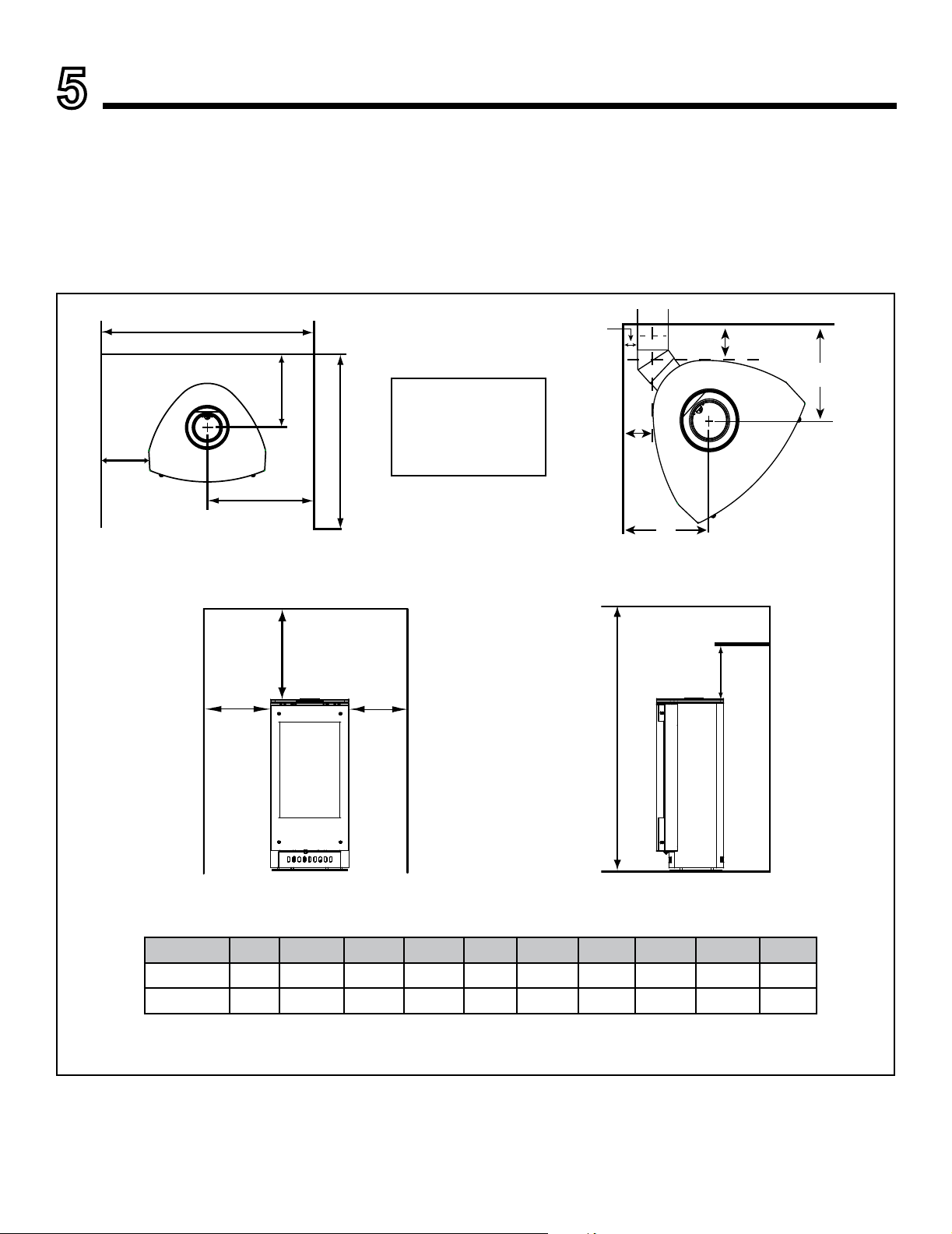
A. Selecting Appliance Location
When selecting a location for the appliance it is important to
consider the required clearances to walls (see Figure 5.1).
WARNING! Risk of Fire or Burns! Provide adequate
clearance around air openings and for service access.
Due to high temperatures, the appliance should be located out of trafc and away from furniture and draperies.
F
B
Note: Mantel must
maintain 1 in. (25
E
mm) clearance
from vertical ue.
A
I
“A” measurement is from gas stove top, not side.
NOTICE: Illustrations reect typical installations and are
FOR DESIGN PURPOSES ONLY. Illustrations/diagrams
are not drawn to scale. Actual installation may vary due to
individual design preference.
Inches 6 10 12 54 36 31 13 10-1/2 15-1/2 5
Millimeters 152 257 308 1372 914 781 337 267 394 127
Figure 5.1 Appliance Locations
Alcove
G
A
A
D
A B C D E F G H I J
H
Heat & Glo • VRT-AUB • 2123-980 Rev. J • 2/13
19
Page 20
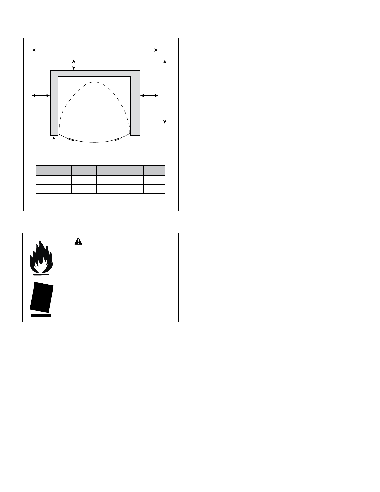
B. Optional Stone Surround Installed
C
B
D
A
STONE SURROUND
A B C D
Inches 3 4 31 36
Millimeters 83 102 781 914
Figure 3.1
WARNING
Fire Risk.
Odor Risk.
Tipping Risk
• Install gas stove on a stable, level platform/
oor strong enough to support gas stove
without tipping.
• USE wood ooring, ceramic tile, brick hearth
or high pressure laminate ooring applied
directly over the sub-ooring material.
A
20
Heat & Glo • VRT-AUB • 2123-980 Rev. J • 2/13
Page 21
6
Termination Locations
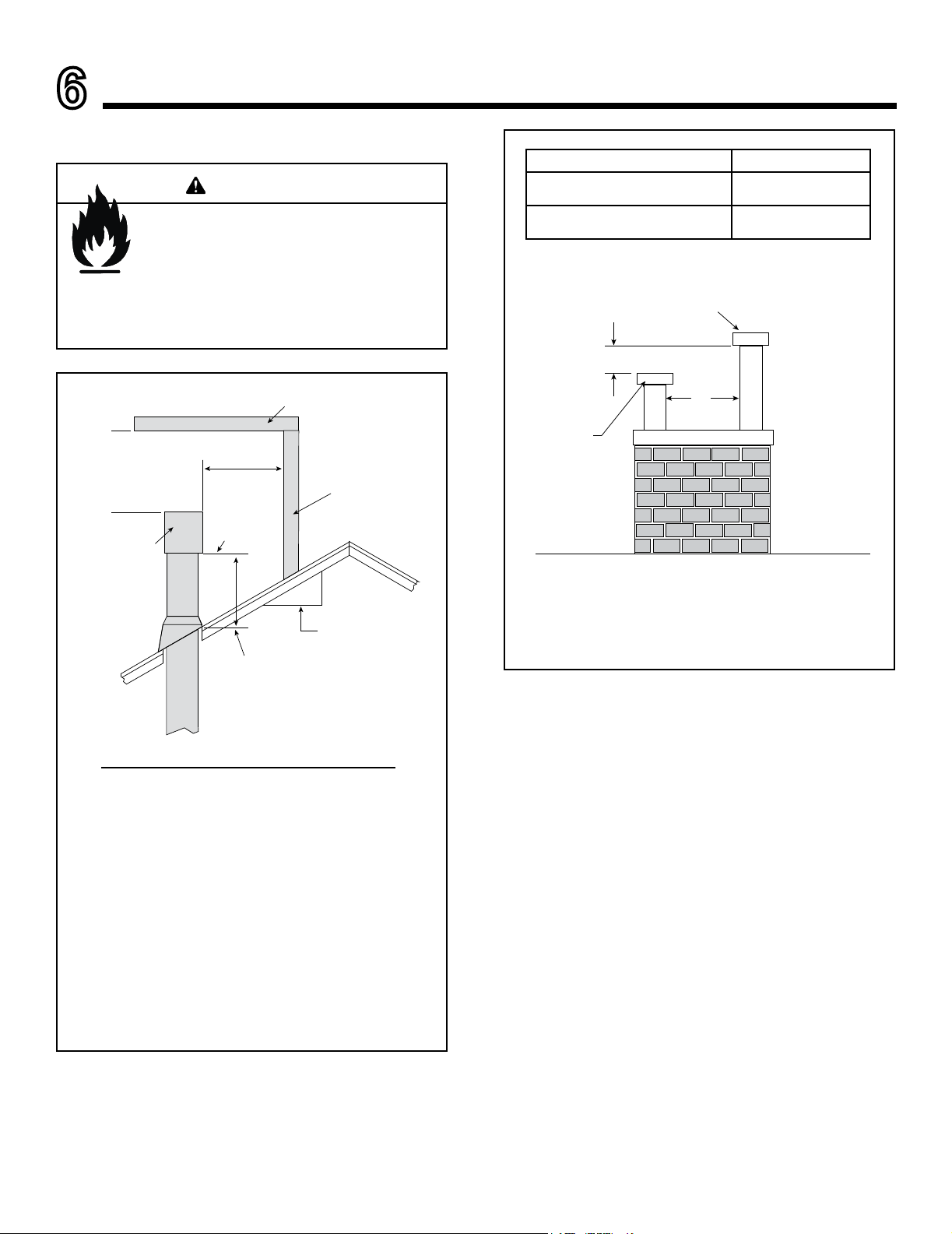
A. Vent Termination Minimum Clearances
WARNING
Fire Risk.
Maintain vent clearance to combustibles as
specied.
• DO NOT pack air space with insulation or other
materials.
Failure to keep insulation or other materials away
from vent pipe may cause overheating and re.
A B
6 in. (minimum) up to 20 in.
(152 mm (minimum) up to 508 mm)
20 in. and over
(508 mm and over)
Gas, Wood or Fuel Oil
Termination Cap
B
18 in. minimum
(457 mm minimum)
0 in. minimum
(0 mm minimum)
HORIZONTAL
OVERHANG
24 in MIN.
(610 mm MIN.)
TERMINATION
CAP
20 in MIN.
(510 mm MIN.)
VERTICAL
WALL
LOWEST
DISCHARGE
OPENING
X
12 in
(305 mm)
ROOF PITCH
IS X/ 12 in.
(305 mm)
H (MIN.) - MINIMUM HEIGHT FROM ROOF
TO LOWEST DISCHARGE OPENING
Angle H (Min.) mm
0°-26.6° .......................................................... 500*
26.6°-30.3° .......................................................... 500*
30.3°-33.7° .......................................................... 500*
33.7°-36.9° .......................................................... 610*
36.9°-39.8° .......................................................... 760
39.8°-42.5° .......................................................... 990
42.5°-45.0° ........................................................1 220
45.0°-49.4° ........................................................1 520
49.4°-53.1° ........................................................1 830
53.1°-56.3° ........................................................2 130
56.3°-59.0° ........................................................2 290
59.0°-60.3° ........................................................2 440
*910 mm minimum in snow regions
A*
Gas
Termination
Cap **
* If using decoratuve cap cover(s), this distance may need to be increased.
Refer to the installation instructions supplied with the decorative cap cover.
** In a staggered installation with both gas and wood or fuel oil terminations, the
wood or fuel oil termination cap must be higher than the gas termination cap.
Figure 6.2 Staggered Termination Caps
Figure 6.1 Minimum Height From Roof To Lowest Discharge
Opening
Heat & Glo • VRT-AUB • 2123-980 Rev. J • 2/13
21
Page 22
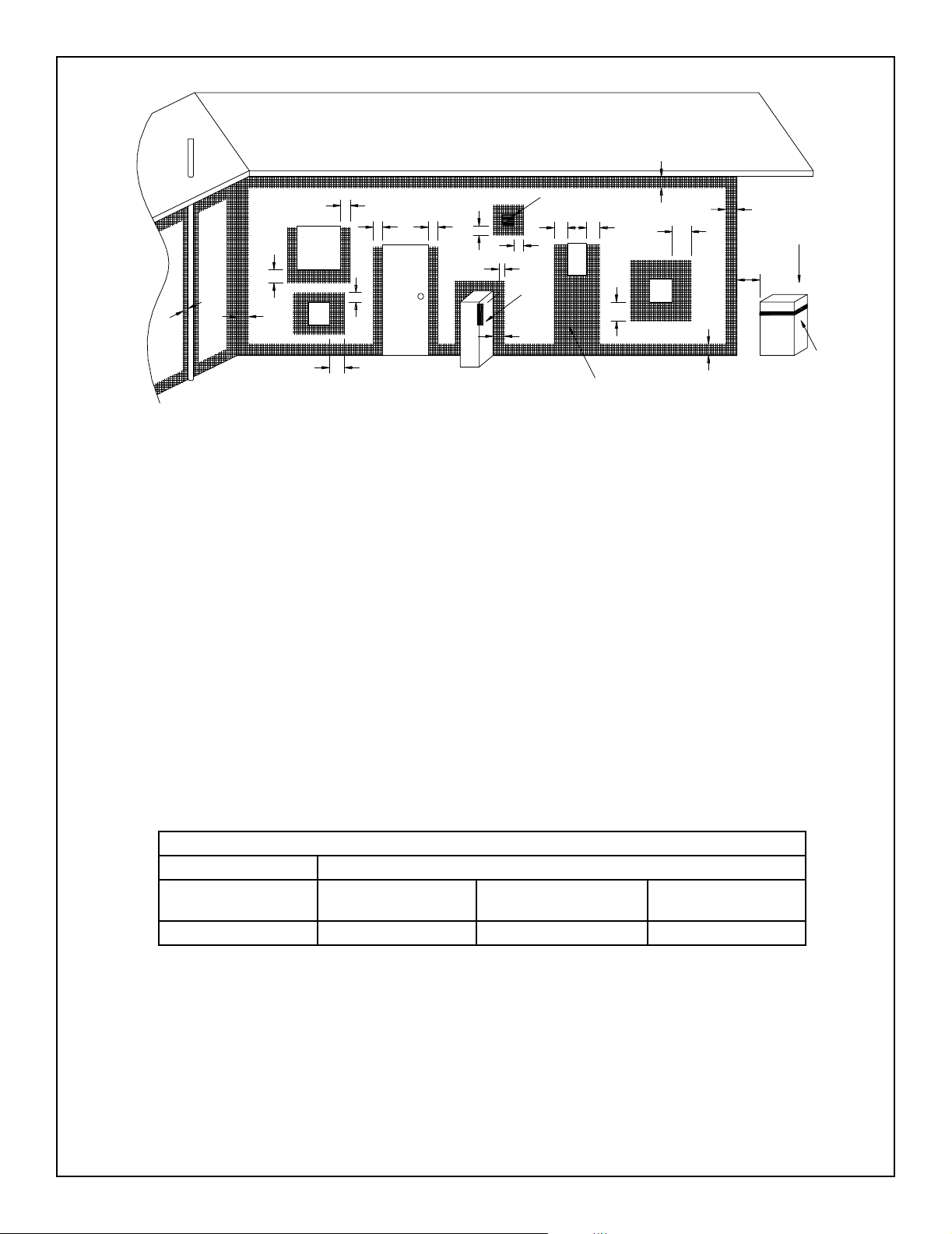
a
j
openable
window
n
f
c
I
door
k
k
h
jj
h
T
e e
h
T
g
P
d
See note 2
d
M
c
See note 3
g
b
T = Flue terminal M = Gas meter Shading indicates prohibited
I = Mechanical air inlet P = Electricity meter or fuse box areas for ue terminals
a - Below eaves, balconies or other projections: MIN. CLEARANCE - in. (mm)
Appliances up to 50 MJ/h input .................................................................................... 12 (300)
Appliances over 50 MJ/h input ............................................................................... 20-1/2 (500)
b - From the ground or above a balcony ............................................................................... 12 (300)
c - From a return wall or external corner ......................................................................... 20-1/2 (500)
d - From a gas meter (M) ...................................................................................................... 39 (1000)
e - From an electricity meter or fuse box (P) ................................................................... 20-1/2 (500)
f - From a drain or soil pipe .................................................................................................... 6 (150)
g - Horizontally from any building structure (unless appliance approved
for closer installation) or obstruction facing a terminal ............................................... 20-1/2 (500)
h - From any other ue terminal, cowl, or combustion air intake .................................... 20-1/2 (500)
j - Horizontally from an openable window, door, non-mechanical air
inlet, or any other opening into a building, with the exception of
sub-oor ventilation:
Appliances up to 150 MJ/h input ............................................................................ 20-1/2 (500)
Appliances over 150 MJ/h input ................................................................................... 60 (1500)
k - From a mechanical air inlet, including a spa blower ....................................................... 60 (1500)
n - Vertically below an openable window, non-mechanical air
inlet or any other opening into a building, with the exception of ...................................... See table
sub-oor ventilation ................................................................................................................ below
T
Space Heaters All other appliances
Up to 50 MJ/h input Up to 50 MJ/h input
6 in. (150 mm) 20 in. (500 mm) 39 in. (1000 mm) 59 in. (1500 mm)
NOTES: 1. All distances are measured vertically or horizontally along the wall to a point
in line with the nearest part of the terminal.
2. Prohibited area below electricity meter or fuse box extends to ground level.
3. See clause 5.13.6.6 for restrictions on a ue terminal under a roofed area.
4. See Appendix J, Figure J1(a) and J2(a) for clearances required from a ue
terminal to a LP Gas cylinder. A ue terminal is considered to be a source of ignition.
MINIMUM CLEARANCES REQUIRED FOR BALANCED FLUE TERMINALS
OR THE FLUE TERMINALS OF OUTDOOR APPLIANCES
Figure 6.3 Minimum Clearances for Termination
22
CLEARANCE
Over 50 MJ/h input and
Up to 150 MJ/h input
Heat & Glo • VRT-AUB • 2123-980 Rev. J • 2/13
Over 50 MJ/h input
Page 23
7
Horizontal
Vertical
8-1/2 in.
(216 mm)
8-1/2 in. (216 mm)
12 in.
(305 mm)
Flue Information
A. Flue Components
These models are approved to use Hearth & Home
Technologies series pipes, components and termination.
Approved components are labeled for identication. This
pipe is tested and listed as an approved component of
the stove.
DO NOT USE FIELD-FABRICATED FLUE COMPONENTS. Refer to the flue manufacturer’s instructions.
This product is approved to be flued either horizontally,
through the side wall or vertically through the roof. You may
flue through a Class A or masonry chimney if an approved
adapter is used.
This gas stove is a balanced ue gas stove. All combustion air must come directly from the outside of the building.
The ue pipe for this unit consists of an inner and an outer
pipe. The inner pipe carries the gas stove exhaust out of
the system, and the outer pipe brings fresh combustion air
into the gas stove.
• A round support box/wall thimble or heat shield is
required when the ueing passes through a combustible
wall.
• A support box or ceiling restop is required when the
ueing passes through a combustible ceiling.
• Roof ashing and a storm collar are required when ueing
passes through the roof.
• Follow instructions provided with the ueing for installation
of these items.
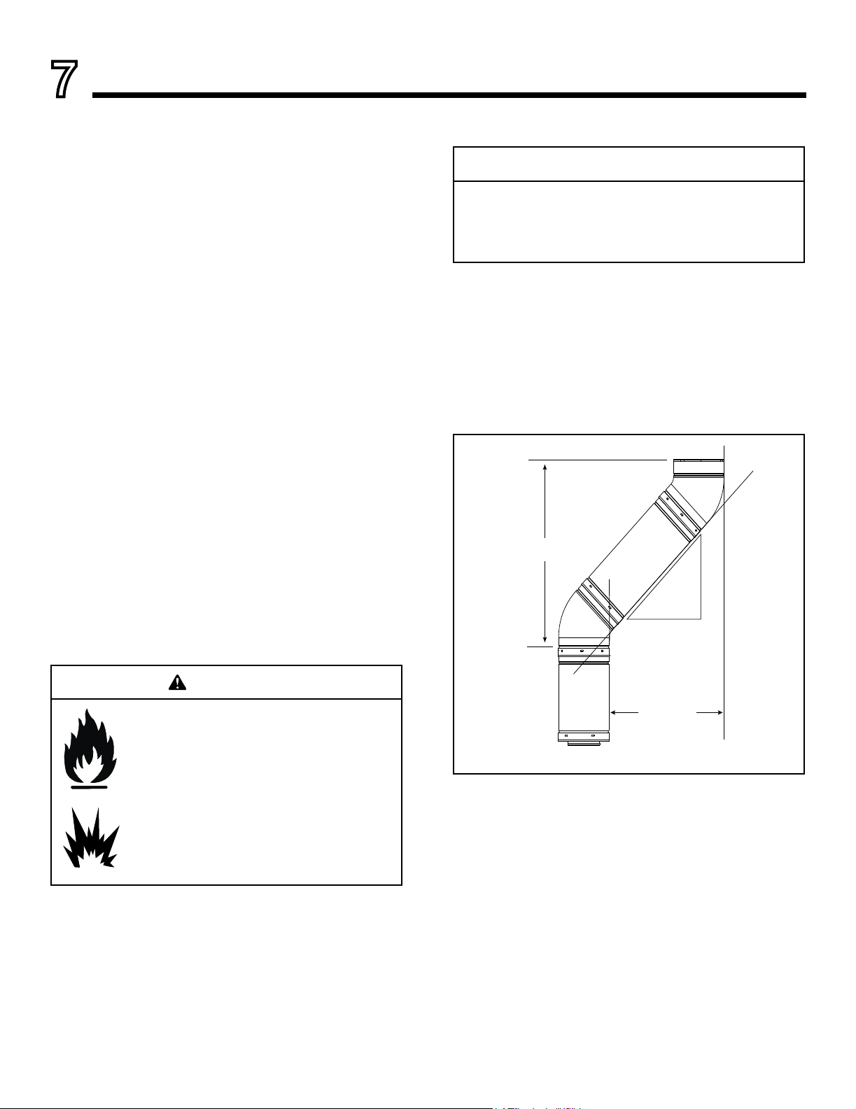
B. Use of Elbows
CAUTION
ALL ue conguration specications MUST be followed.
• This product is tested and listed to these specications.
• Appliance performance will suffer if specications are not
followed.
Diagonal runs have both vertical and horizontal ue aspects
when calculating the effects. Use the rise for the vertical aspect and the run for the horizontal aspect (see Figure 7.1).
Two 45º elbows may be used in place of one 90º elbow.
On 45º runs, 12 in. (305 mm) of diagonal is equal to 8-1/2
in. (216 mm) horizontal run and 8-1/2 in. (216 mm) vertical
run. A length of straight pipe is allowed between two 45º
elbows (see Figure 7.1).
WARNING
Fire Hazard.
Explosion Risk.
Asphyxiation Risk.
Do NOT connect this gas stove to a chimney
ue serving a separate solid-fuel or gas burning
gas stove.
• Flue this gas stove directly outside.
• Use separate ue system for this gas stove.
May impair safe operation of this gas stove or
other gas stoves connected to the ue.
Heat & Glo • VRT-AUB • 2123-980 Rev. J • 2/13
Figure 7.1
C. Measuring Standards
Vertical and horizontal measurements were made using
the following standards.
• Pipe measurements are from center line to center line.
• Horizontal terminations are measured to the outside
edge of termination cap. See Figure 7.3.
• Horizontal pipe should be installed level with no rise.
23
Page 24

D. Flueing Diagrams
STRAIGHT UP
VERTICAL FLUE
V
38 ft. (11.58 m) Maximum
For Natural, Propane and Butane Gases.
Note: For this type of installation, the vertical
ue restrictor must be added. See section H
for instructions.
V
Figure 7.2
STRAIGHT OUT
HORIZONTAL FLUE
H
2 ft. (610 mm) Maximum
For Natural, Propane and Butane Gases.
H
Figure 7.3
24
Heat & Glo • VRT-AUB • 2123-980 Rev. J • 2/13
Page 25

V
Figure 7.4
Natural Gas • One 90° Elbow System
V Minimum H Maximum
1-1/2 ft. 457 mm 4-1/2 ft. 1.37 m
3 ft. 914 mm 9 ft. 2.74 m
4-1/2 ft. 1.37 m 13-1/2 ft. 4.12 m
6 ft. 1.83 m 16 ft. 4.88 m
V + H = Max. 38 ft. (11.58 m) H Max. = 16 ft. (4.88 m)
Propane • One 90° Elbow System
V Minimum H Maximum
1-1/2 ft. 457 mm 3 ft. 914 mm
3 ft. 914 mm 6 ft. 1.83 m
4-1/2 ft. 1.37 m 9-1/2 ft. 2.88 m
6 ft. 1.83 m 12 ft. 3.66 m
V + H = Max. 38 ft. (11.58 m) H Max. = 12 ft. (3.66 m)
Butane • One 90° Elbow System
V Minimum H Maximum
1-1/2 ft. 457 mm 1-1/2 ft. 457 mm
H
3 ft. 914 mm 3 ft. 914 mm
4-1/2 ft. 1.37 m 4-1/2 ft. 1.37 m
6 ft. 1,83 m 6 ft. 1.83 m
V + H = Max. 33 ft. (10.06 m) H Max. = 6 ft. (1.83 m)
Natural Gas • One 90° Elbow System
V Minimum H Maximum
1-1/2 ft. 457 mm 4-1/2 ft. 1.37 m
3 ft. 914 mm 9 ft. 2.74 m
4-1/2 ft. 1.37 m 13-1/2 ft. 4.12 m
6 ft. 1.83 m 16 ft. 4.88 m
V + H = Max. 36 ft. (10.97 m) H Max. = 16 ft. (4.88 m)
Propane • One 90° Elbow System
V Minimum H Maximum
1-1/2 ft. 457 mm 3 ft. 914 mm
3 ft. 914 mm 6 ft. 1.83 m
4-1/2 ft. 1.37 m 9-1/2 ft. 2.88 m
6 ft. 1.83 m 12 ft. 3.66 m
V + H = Max. 36 ft. (10.97 m) H Max. = 12 ft. (3.66 m)
Butane • One 90° Elbow System
V Minimum H Maximum
4 ft. 1.22 m 3 ft. 914 mm
4-1/2 ft. 1.37 m 4-1/2 ft. 1.37 m
6 ft. 1.83 m 6 ft. 1.83 m
V + H = Max. 33 ft. (10.06 m) H Max. = 6 ft. (1.83 m)
H
V
Figure 7.5
Heat & Glo • VRT-AUB • 2123-980 Rev. J • 2/13
25
Page 26

Natural Gas • Two 90° Elbows System
V Minimum H Maximum H1 + H2 Max.
1-1/2 ft. 457 mm 1-3/4 ft. 530 mm 3-1/2 ft. 1.07 m
3 ft. 914 mm 3-1/2 ft. 1.07 m 7 ft. 2.13 m
4-1/2 ft. 1.37 m 5-1/2 ft. 1.68 m 11-1/2 ft. 3.5 m
6 ft. 1.83 m 7 ft. 2.13 m 14-1/2 ft. 4.42 m
V + H1 + H2 = Max. 36 ft. (10.97 m) H1 Max. = 7 ft. (2.13 m) H1 + H2 = Max. 15 ft. (4.57 m)
Propane • Two 90° Elbows System
V Minimum H Maximum H1 + H2 Max.
1-1/2 ft. 457 mm 15 in. 390 mm 2-1/4 in. 690 mm
3 ft. 914 mm 30 in. 750 mm 4-1/2 ft. 1.37 m
4-1/2 ft. 1.37 m 3-1/2 ft. 1.07 m 7 ft. 2.13 m
6 ft. 1.83 m 5 ft. 1.52 m 9 ft. 2.74 m
V + H1 + H2 = Max. 35 ft. (10.66 m) H1= Max. 5 ft. (1.52 m) H1+H2 = Max. 9 ft. (2.74 m)
Butane • Two 90° Elbows System
V Minimum H Maximum H1 + H2 Max.
4 ft. 1.22 m 1-1/2 ft. 457 mm 2 ft. 610 mm
4-1/2 ft. 1.37 m 1-1/2 ft. 457 mm 2-1/4 ft. 690 mm
6 ft. 1.83 m 2-1/4 ft. 690 mm 3 ft. 914 mm
V + H1 + H2 = Max. 33 ft. (10.06 m) H1= Max. 2-1/4 ft. (690 mm) H1 + H2 = Max. 3 ft. (914mm)
Figure 7.6
V
H
2
H
1
26
Heat & Glo • VRT-AUB • 2123-980 Rev. J • 2/13
Page 27

Natural Gas • Two 90° Elbows System
V Minimum H Maximum H1 + H2 Max.
1-1/2 ft. 457 mm 2 ft. 610 mm 3-1/2 ft. 1.07 m
3 ft. 914 mm 3-1/2 ft. 1.07 m 7-1/2 ft. 2.28 m
4-1/2 ft. 1.37 m 5-1/2 ft. 1.68 m 11-1/2 ft. 3.5 m
6 ft. 1.83 m 7 ft. 2.13 m 15 ft. 4.57 m
V + H1 + H2 = Max. 33 ft. (10.06 m) H1 Max. = 7 ft. (2.13 m) H1 + H2 = Max. 15 ft. (4.57 m)
Propane • Two 90° Elbows System
V Minimum H Maximum H1 + H2 Max.
1-1/2 ft. 457 mm 15 in. 390 mm 2-1/4 in. 69 cm
3 ft. 914 mm 30 in. 750 mm 4-1/2 ft. 1.37 m
4-1/2 ft. 1.37 m 3-1/2 ft. 1.07 m 7 ft. 2.13 m
6 ft. 1.83 m 5 ft. 1.52 m 9 ft. 2.74 m
V + H1 + H2 = Max. 33 ft. (10.06 m) H1= Max. 5 ft. (1.52 m) H1+H2 = Max. 9 ft. (2.74 m)
Butane • Two 90° Elbows System
V Minimum H Maximum H1 + H2 Max.
4 ft. 1.22 m 1-1/2 ft. 457 mm 2 ft. 610 mm
4-1/2 ft. 1.37 m 1-1/2 ft. 457 mm 2-1/4 ft. 690 mm
6 ft. 1.83 m 2-1/4 ft. 69 cm 3 ft. 914 mm
V + H1 + H2 = Max. 33 ft. (10.06 m) H1= Max. 2-1/4 ft. (690 mm) H1 + H2 = Max. 3 ft. (914 mm)
Figure 7.7
H
2
V
H
1
Heat & Glo • VRT-AUB • 2123-980 Rev. J • 2/13
27
Page 28

Natural Gas • Two 90° Elbows System
V Minimum H Maximum
1 ft. 305 mm 3 ft. 914 mm
2 ft. 610 mm 6 ft. 1.83 m
3 ft. 914 mm 9 ft. 2.74 m
4 ft. 1.22 m 12 ft. 3,66 m
5 ft. 1.52 m 15 ft. 4.57 m
V1 + V2 + H = Max. 36 ft. (10.97 m) H = Max. 15 ft. (4.57 m)
V
2
Figure 7.8
Natural Gas • Two 90° Elbows System
V Minimum H1 + H2 Maximum
2 ft. 610 mm 5-1/2 ft. 1.68 m
3 ft. 914 mm 8 ft. 2.44 m
4 ft. 1.22 m 10-1/2 ft. 3,2 m
5 ft. 1.52 m 13 ft. 3.96 m
V1 + V2 + H = Max. 36 ft. (10.97 m) H = Max. 15 ft. (4.57 m)
Propane • Two 90° Elbows System
V Minimum H Maximum
1 ft. 305 mm 2 ft. 610 mm
H
V
1
H
2
2 ft. 610 mm 4 ft. 1.22 m
3 ft. 914 mm 6 ft. 1.83 m
4 ft. 1.22 m 8 ft. 2.44 m
5 ft. 1.52 m 10 ft. 3.05 m
V1 + V2 + H = Max. 36 ft. (10.97 m) H = Max. 10 ft. (3.05 m)
Butane • Two 90° Elbows System
V Minimum H Maximum
1 ft. 305 mm 1 ft. 305 mm
2 ft. 610 mm 2 ft. 610 mm
3 ft. 914 mm 3 ft. 914 mm
4 ft. 1.22 m 4 ft. 1.22 m
5 ft. 1.52 m 5 ft. 1.52 m
V1 + V2 + H = Max. 33 ft. (10.06 m) H = Max. 3-1/2 ft. (1.07 m)
H
1
Propane • Two 90° Elbows System
V Minimum H1 + H2 Maximum
2 ft. 610 mm 3-1/2 ft. 1.07 m
3 ft. 914 mm 5 ft. 1.52 m
4 ft. 1.22 m 6-1/2 ft. 1.98 m
5 ft. 1.52 m 8-1/2 ft. 2.59 m
V1 + V2 + H = Max. 36 ft. (10.97 m) H = Max. 10 ft. (3.05 m)
Butane • Two 90° Elbows System
V Minimum H1 + H2 Maximum
2 ft. 610 mm 1-1/2 ft. 460 mm
3 ft. 914 mm 2 ft. 610 mm
4 ft. 1.22 m 2-1/2 ft. 760 mm
5 ft. 1.52 m 3-1/2 ft. 1.07 m
V1 + V2 + H = Max. 33 ft. (10.06 m) H = Max. 3-1/2 ft. (1.07 m)
Figure 7.9
28
V
Heat & Glo • VRT-AUB • 2123-980 Rev. J • 2/13
Page 29

Natural Gas • Three 90° Elbows System
V Minimum H Maximum H1 + H2 Max.
1-1/2 ft. 457 mm 1-3/4 ft. 530 mm 3-1/2 ft. 1.07 m
3 ft. 914 mm 3-1/2 ft. 1.07 m 7-1/2 ft. 2.28 m
4-1/2 ft. 1.37 m 5-1/2 ft. 1.68 m 11-1/2 ft. 3.5 m
6 ft. 1.83 m 7 ft. 2.13 m 15 ft. 4.57 m
V + H1 + H2 = Max. 36 ft. (10.97 m) H1 Max. = 7 ft. (2.13 m) H1 + H2 = Max. 15 ft. (4.57 m)
Propane • Three 90° Elbows System
V Minimum H Maximum H1 + H2 Max.
1-1/2 ft. 457 mm 1 ft. 305 mm 2-1/4 in. 690 mm
3 ft. 914 mm 2 ft. 610 mm 4-1/2 ft. 1.37 m
4-1/2 ft. 1.37 m 3-1/2 ft. 1.07 m 7 ft. 2.13 m
6 ft. 1.83 m 6 ft. 1.83 m 9 ft. 2.74 m
V + H1 + H2 = Max. 36 ft. (10.97 m) H1= Max. 6 ft. (1.83 m) H1+H2 = Max. 9 ft. (2.74 m)
Butane • Three 90° Elbows System
V Minimum H Maximum H1 + H2 Max.
1-1/2 ft. 457 mm 6 in. 150 mm 1 ft. 305 mm
3 ft. 914 mm 8 in. 230 mm 2 ft. 610 mm
4-1/2 ft. 1.37 m 1-1/4 in. 380 mm 2-1/2 ft. 760 mm
6 ft. 1.83 m 1-1/2 in. 457 mm 3-1/2 ft. 1.07 m
V + H1 + H2 = Max. 33 ft. (10.06 m) H1= Max. 1-1/2 ft. (457 mm) H1 + H2 = Max. 3-1/2 ft. (1.07 m)
Figure 7.10
V
2
V
H
2
H
1
1
Heat & Glo • VRT-AUB • 2123-980 Rev. J • 2/13
29
Page 30

Natural Gas • Three 90° Elbows System
V Minimum H Maximum H1 + H2 Max.
1-1/2 ft. 457 mm 1-3/4 ft. 530 mm 3-1/4 ft. 1,0 m
3 ft. 914 mm 3-1/2 ft. 1,07 m 6-1/2 ft. 1,98 m
4-1/2 ft. 1,37 m 5-1/2 ft. 1,68 m 10 ft. 3,05 m
6 ft. 1,83 m 7 ft. 2,13 m 13 ft. 3,96 m
V + H1 + H2 = Max. 36 ft. (10.97 m) H1 Max. = 7 ft. (2.13 m) H1 + H2 = Max. 13 ft. (3.96 m)
Propane • Three 90° Elbows System
V Minimum H Maximum H1 + H2 Max.
1-1/2 ft. 457 mm 1 ft. 305 mm 1-3/4 ft. 530 mm
3 ft. 914 mm 2 ft. 610 mm 3-1/2 ft. 1.07 m
4-1/2 ft. 1.37 m 3-1/2 ft. 1.07 m 5-1/2 ft. 1.68 m
6 ft. 1.83 m 6 ft. 1.83 m 7 ft. 2.13 m
V + H1 + H2 = Max. 33 ft. (10.06 m) H1= Max. 6 ft. (1.83 m) H1+H2 = Max. 7 ft. (2.13 m)
Butane • Three 90° Elbows System
V Minimum H Maximum H1 + H2 Max.
2 ft. 610 mm 6 in. 150 mm 1 ft. 305 mm
3 ft. 914 mm 8 in. 230 mm 1-1/4 in. 380 mm
4-1/2 ft. 1.37 m 1-1/4 in. 380 mm 2-1/2 ft. 760 mm
6 ft. 1.83 m 1-1/2 in. 457 mm 3-1/4 ft. 1.0 m
V + H1 + H2 = Max. 33 ft. (10.06 m) H1= Max. 1-1/2 ft. (457 mm) H1 + H2 = Max. 3-1/4 ft. (1.0 m)
Figure 7.11
30
V
2
V
H
2
1
H
1
Heat & Glo • VRT-AUB • 2123-980 Rev. J • 2/13
Page 31

E. Flue Pipe Assembly F. Horizontal Penetration Framing
90 DEGREE
ELBOW
Note: Align seams to engage pipe,
then rotate counterclockwise to lock
Figure 7.12
Step 1.
Balanced flue pipe is designed with a locking connection.
To connect the flue system to the gas stove flue outlet:
• Lock the ue components into place by sliding the pipe
section onto the collar.
• Align the seam of the pipe and seam of collar to allow
engagement. Rotate the ue component to lock into
place. Use this procedure for all ue components. See
Figure 7.12.
• Continue add ing flue compo nents , locking each
succeeding component into place.
• Ensure that each succeeding ue component is securely
tted and locked into the preceding component.
WARNING
Figure 7.13
PIPE LENGTH
PIPE LENGTH
WALL THIMBLE
WALL THIMBLE
COVER
TERMINATION CAP
Step 2.
For installations using a round support box/wall thimble
(check pipe manufacturer's instructions), mark the wall for
a 9 in. x 9 in. (229 mm x 229 mm) square hole. The center
of the square hole should line up with the center line of
the horizontal pipe. Cut and frame the hole in the exterior
wall where the flue will be terminated. If the wall being
penetrated is constructed of noncombustible material, i.e.
masonry block or concrete, a 7 in. (178 mm) diameter
hole is acceptable.
Fire Risk.
Explosion Risk.
Combustion Fume Risk.
Use ue run supports per installation instructions.
Connect ue sections per installation instructions.
• Maintain all clearances to combustibles.
• Do NOT allow ue to sag below connection
point to gas stove.
• Maintain specied slope (if required).
Improper support may allow ue to sag or separate.
Step 3.
Position the horizontal termination cap in the center of the
9 in. x 9 in. (229 mm x 229 mm) square hole and run a
bead of non-hardening mastic around its outside edges,
to make a seal between it and the wall. Attach termination
cap to the exterior wall with the four wood screws provided. The arrow on the flue cap should be pointing up.
Heat & Glo • VRT-AUB • 2123-980 Rev. J • 2/13
31
Page 32

FIG. A 90 DEGREE ELBOW
P la c e m ark w h e re p r o trud e s th ro ug h
ex t e rior w all to cu t o ff e xc es s.
O
90 E LB OW
C E NT E R
LIN E
U S E H EAT SH IEL D OR W A L L TH IM B L E
P IP E
LE N G T H
TR IM
R IN G
P IP E L E N G T H
FIG. B MINIMUM CLEARANCE
INTERIOR WALL
2 in. (51 mm) clearance
from rear of stove
CENTER LINE
Figure 7.14
MINIMUM OF 6 in. (152 mm)
OF PIPE THROUGH THE WALL
WALL THIMBLE
HEAT SHIELD OVER
TOP HALF OF PIPE
TRIM RING
32
Heat & Glo • VRT-AUB • 2123-980 Rev. J • 2/13
Page 33

G. Slim Line Wall Thimble
BEFORE YOU BEGIN:
Review the ueing congurations in Figures A, B and C
on the next page.
CAUTION! Risk of Cuts, Abrasions or Flying Debris.
Wear protective gloves and safety glasses during instal-
lation. Sheet metal edges are sharp.
1. Assembling Slim Line Trim Ring and Heat Shield
Figure 7.15
Lay the trim ring on at surface and bend up the six
welded brackets into a 90 degree position. The brackets
along the outer edge of the ring are for locating the ring in
the center of the hole.
Figure 7.17
Attach the heat shield to the trim ring with the four screws
provided. Screws go through the heat shield and into the
brackets on the trim ring.
2. Installing Slim Line Trim Ring and Heat Shield
Measure from the oor to the center of the ue pipe. Cut
out a 9-1/2 in. (240 mm) hole in the wall. Hold the trim
ring/heat shield assembly in place and put a mark on the
shield with a black marker where it protrudes through the
exterior wall. Figure A on the previous page.
Use that mark as a guide to trim off excess heat shield
with a pair of sheet metal shears.
Figure 7.16
The heat shield is shipped at and must be hand bent into
a half circle before attaching it to the trim ring. Bend the
heat shield as shown.
Heat & Glo • VRT-AUB • 2123-980 Rev. J • 2/13
Figure 7.18
When installing the trim ring/heat shield assembly make
sure the trim ring is centered in the hole and that the
shield is above the pipe. There must be a minimum of 20
mm minimum clearance maintained to combustibles from
the top of the heat shield.
Ensure that framing on the inside of the wall is a minimum
inner framing diameter of 9 in. x 9 in. (229 mm x 229 mm).
The four trim ring mounting screws provided should be
replaced with appropriate fasteners for stucco, brick, concrete, or other types of sidings.
33
Page 34

CONNECTED TO
WALL STRAP
WALL
STRAP
TWO 45 DEGREE
ELBOWS
METAL STRAP
H. Vertical Termination
STORM COLLAR
VERTICAL
TERMINATION CAP
FLASHING
FIRESTOP
SUPPORT
BOX
PIPE LENGTH
On vertical terminations use SLP-TVHW.
Figure 7.19
Step 1.
Check the installation instructions for required 10 in. (254
mm) clearances (air space) to combustibles when passing through ceilings, walls, roofs, enclosures, attic rafters,
or other nearby combustible surfaces. (See Figure 7.19).
Check the instructions for maximum vertical rise of the
flueing system, and any maximum horizontal offset limitations. All offsets must fall within the set parameters of the
flueing diagrams located in Section 7.
NOTE: Maximum vertical rise allowable is 38 ft. (11.58 m)
Figure 7.20.
11.58 m
(38 ft.)
MAXIMUM
Figure 7.20
Step 2.
Set the gas stove in its desired location. Drop a plumb
bob down from the ceiling to the position of the gas stove
flue exit, and mark the location where the flue will penetrate the ceiling. Drill a small hole at this point. Next, drop
a plumb bob from the roof to the hole previously drilled
in the ceiling, and mark the spot where the flue will penetrate the roof. Determine if ceiling joists, roof rafters, or
other framing will obstruct the flueing system. You may
wish to relocate the gas stove, or to offset, as shown in
Figure 7.21 to avoid cutting load bearing members.
34
WARNING
Fire Risk.
Explosion Risk.
Maintain ue clearance to combustibles as
specied.
• Do not pack air space with insulation or other
materials.
Failure to keep insulation or other materials
away from ue pipe may cause re.
Figure 7.21
Heat & Glo • VRT-AUB • 2123-980 Rev. J • 2/13
Page 35

Step 3.
ROUND CEILING
SUPPORT BOX/WALL
THIMBLE COVER
229 mm x 229 mm
40 mm LONG
WOOD SCREWS
CEILING JOISTS
FRAMING
SHINGLES OVERLAP ON
TOP EDGE OF FLASHING
CAP AND STORM COLLAR NOT SHOWN FOR CLARITY
To install the round support box/wall thimble cover in a flat
ceiling, cut a 229 mm square hole in the ceiling, centered
on the hole drilled in Step 2. Frame the hole as shown in
Figure 7.22.
Figure 7.22
Step 4.
Assemble the desired lengths of pipe and elbows necessary to reach from the gas stove up through the round support box. Ensure that all pipe and elbow connections are
in their fully twist-locked position. Assemble as instructed.
Step 5.
Cut a hole in the roof centered on the small drill hole placed
in the roof in Step 2. The hole should be of sufficient size
to meet the minimum requirements for clearance to combustibles, as specified. Continue to assemble lengths
of pipe and elbows necessary to reach from the ceiling
support box/wall thimble up through the roof line. Galvanized pipe and elbows may be utilized in the attic, as well
as above the roofline. The galvanized finish is desirable
above the roofline, due to its higher corrosion resistance
(compared to black pipe).
Figure 7.23
Step 7.
Continue to assemble pipe sections until the height of the
flue (before adding the termination cap) meets the minimum local code requirements. Note that for steep roof
pitches, the flue height must be increased. See Roof
Pitch Table (Figure 4.3). In high wind conditions, nearby
trees adjoining rooflines, steep pitched roofs, and other
similar factors can result in poor draft, or down drafting. In
these cases increasing the flue height or switching to the
high wind termination cap may solve this problem.
Step 8.
Slip the storm collar over the pipe, and push it down to
the top of the flashing (Figure 7.24). Use non-hardening
sealant above and below the joint between the storm
collar and the pipe.
SECURE FLASHING WITH
NON-HARDENING SEALANT
AND ROOFING NAILS
NOTE:
(1) If an offset is necessary in the attic to avoid obstruc-
tions, it is important to support the flue pipe every
91.4cm to avoid excessive stress on the elbows, and
possible separation. Wall straps are available for this
purpose, Figure 7.10, page 15.
(2) Whenever possible, use 45° elbows, instead of 90°
elbows. The 45° elbow offers less restriction to the
flow of flue gases and intake air.
Step 6.
Slip the flashing over the pipe section(s) protruding
through the roof. Secure the base of the flashing to the
roof with roofing nails. Ensure the roofing material overlaps the top edge of the flashing as shown in Figure 7.23.
Verify that the chimney is the required height above the
roof. See roof pitch table, Figure 4.3.
Heat & Glo • VRT-AUB • 2123-980 Rev. J • 2/13
Figure 7.24
35
Page 36

Step 9.
Twist-lock the flue cap and seal.
Note: For multi-story vertical installations, a ceiling firestop
is required at the second floor, and any subsequent floors
(Figure 7.25). The opening should be framed to 9 in. x 9
in. (229 mm x 229 mm) inside dimensions, in the same
manner as shown in Figure 7.22.
NAILS
CEILING FIRESTOP
MIN. 25.4 mm
CLEARANCE
I. Vertical Flue Restrictor
If the fireplace installation requires a vertical flue off the
top of the unit with no horizontal flue or elbows, the vertical
flue restrictor must be added. Reinstall heat shield when
completed. See Figure 7.26.
FLUE
RESTRICTOR
PLATE
HEAT SHIELD
MIN. 25.4 mm
CLEARANCE
Figure 7.25
MIN. 25.4 mm
CLEARANCE
MIN. 25.4 mm
CLEARANCE
WARNING
Fire Risk.
Explosion Risk.
• Any occupied areas above the first floor,
including closets and storage spaces, which
the vertical flue passed through must be
enclosed. The enclosure may be framed
and sheetrocked with standard construction
materials; however, refer to these installation
instructi ons for the minimum allowable
clearance between the outside of the flue
pipe and the combustible surfaces of the
enclosure. Do not fill any of the required air
space with insulation.
Figure 7.26
36
Heat & Glo • VRT-AUB • 2123-980 Rev. J • 2/13
Page 37

8
Vent Clearances and Framing
A. Pipe Clearances to Combustibles
WARNING! Risk of Fire! Maintain air space clearance to
vent. DO NOT pack insulation or other combustibles:
• Between ceiling restops
• Between wall shield restops
• Around vent system
Failure to keep insulation or other material away from
vent pipe may cause over heating and re.
Note: Heat shields MUST overlap by a minimum of 1-1/2 in. (38 mm).
• If wall thickness is less than 4 in. (102 mm) the existing heat shields must be field
trimmed.
3 in. (76 mm)
top clearance
1 in. (25 mm)
clearance around
vertical sections
Heat
Shield
Wall
Shield
Firestop
WALL
3 in. (76 mm)
top clearance *
Heat
Shield
1 in. (25 mm)
clearance
bottom & sides
B. Wall Penetration Framing
Combustible Wall Penetration
Whenever a combustible wall is penetrated, you must
frame a hole for the wall shield restop(s). The wall shield
restop maintains minimum clearances and prevents cold
air inltration.
• The opening must be framed on all four sides using the
same size framing materials as those used in the wall
construction.
• SLP pipe - A wall shield restop must be placed on each
side of an interior wall. A minimum 1-1/2 inch (38 mm)
overlap of attached heat shields must be maintained.
• See Section 10.H for information for regarding the installation of a horizontal termination cap.
Non-Combustible Wall Penetration
If the hole being penetrated is surrounded by noncombustible materials such as concrete, a hole with diameter
one inch greater than the pipe is acceptable.
Whenever a non-combustible wall is penetrated, the wall
shield restop is only required on one side and no heat
shield is necessary.
Heat
Shield
Wall
Shield
Firestop
WALL
* When using SLP pipe, minimum clearances from the vent pipe to combustible
materials at inside wall firestops are: Top: 2-1/2 in. (64 mm)
Bottom: 1/2 in. (13 mm)
Sides: 1 in. (25 mm)
3 in. (76 mm)
top clearance *
Heat
Shield
1 in. (25 mm)
clearance
bottom & sides
Figure 8.1 Horizontal Venting Clearances To Combustible
Materials
Note: A 6 in. (152 mm) section of straight ue
must be attached to the replace before a 90°
elbow.
* Unit shown with 1-1/2 ft. (457.2 mm) of
vertical pipe. Vertical section will vary by gas.
Refer to vent chart for minimum vertical.
A*
VRT-N-AUB
VRT-P-AUB
10 in.
(254 mm)
10 in.
(254 mm)
B*
Millimeters
Millimeters
Inches
Inches
10 in.
(254 mm)
(254 mm)
C
D
10 in.
A* B* C D
69.3 34-3/4 68.3 33-3/4
1761 883 1736 857
69.3 34-3/4 68.3 33-3/4
1761 883 1736 857
* Shows center of vent framing hole for top or rear venting. The center of
the hole is one 1 in. (25.4 mm) above the center of the horizontal vent
pipe.
Figure 8.2 Wall Penetration
Heat & Glo • VRT-AUB • 2123-980 Rev. J • 2/13
37
Page 38

C. Install the Ceiling Firestop
A ceiling restop MUST be used between
oors and attics.
• SLP pipe only - Frame opening 9 in. x 9
in. (229 mm x 229 mm) whenever the vent
penetrates a ceiling/oor (see Figure 8.3).
• Frame the area with the same sized lumber
as used in ceiling/oor joist.
• The ceiling restop may be installed above or
below the ceiling joists when installed with a
attic insulation shield. It must be under joists
between oors that are not insulated. Refer
to Figure 8.4.
• Secure with three fasteners on each side.
WARNING! Risk of Fire! DO NOT pack insu-
lation around the vent. Insulation must be kept
back from the pipe to prevent overheating.
ATTIC ABOVE
A
A
Figure 8.3 Installing Ceiling Firestop
INSTALL ATTIC INSULATION SHIELDS
BEFORE OR AFTER INSTALLATION OF VENT SYSTEM
PIPE
SLP
A
9 in. (229 mm)
38
CEILING FIRESTOP
INSTALLED BELOW CEILING
Figure 8.4 Installing the Attic Shield
Heat & Glo • VRT-AUB • 2123-980 Rev. J • 2/13
3 FASTENERS
PER SIDE
CEILING FIRESTOP
INSTALLED ABOVE CEILING
Page 39

D. Install Attic Insulation Shield
WARNING! Fire Risk. DO NOT allow loose materials or
insulation to touch vent. Hearth & Home Technologies requires the use of an attic shield.
An attic shield constructed of 26 gauge minimum metal that
extends at least 2 in. (51 mm) above insulation is required.
Attic shields must meet specied clearance and be secured in place.
Flat Ceiling Installation
• Remove one shield from box.
NOTICE: Cut previously installed batt insulation to make
room for the attic insulation shield.
• Wrap shield around pipe if pipe is already installed in
area to be insulated.
• Match the three holes in each side and fasten with three
screws to form a tube.
• Bend three tabs on the bottom of the shield outward to
allow attachment to the ceiling restop.
• Bend the remaining bottom tabs inward 90º to maintain
the air space between the pipe and the shield. Set the
shield on the ceiling restop and attach to the restop.
• Bend all tabs inward 90º around the top of the shield.
These tabs must be used to prevent blown insulation
from getting between the shield and vent pipe, and to
maintain air space clearance.
BEND ALL TABS INWARD 90°
TO MAINTAIN CLEARANCE
AND PREVENT INSULATION
FROM FALLING INSIDE
INSERT 3
SCREWS
Figure 8.5 Attic Insulation Shield
BEND 3 TABS
OUTWARD TO
FASTEN TO CEILING
FIRESTOP-BEND
REMAINING TABS
INWARD 90 DEGREES
TO MAINTAIN
CLEARANCE
Vaulted Ceiling Installation
• Remove one shield from box.
NOTICE: Cut previously installed batt insulation to make
room for the attic insulation shield.
• Cut the attic insulation shield (if application is for vaulted
ceiling) to t your ceiling pitch. Snip cut edge to recreate
1 in. (25 mm) bend tabs all the way around the bottom.
• Wrap shield around pipe if pipe is already installed in
area to be insulated.
• Match the three holes in each side and fasten with three
screws to form a tube.
• Bend three tabs on the bottom of the shield outward to
allow attachment to the ceiling restop.
• Bend the remaining bottom tabs inward 90º to maintain
the air space between the pipe and the shield. Set the
shield on the ceiling restop and attach to the restop.
• Bend all tabs inward 90º around the top of the shield.
These tabs must be used to prevent blown insulation
from getting between the shield and vent pipe, and to
maintain air space clearance.
Heat & Glo • VRT-AUB • 2123-980 Rev. J • 2/13
39
Page 40

9
Appliance Setup
A. Remove Shipping Materials
Remove shipping materials from inside or underneath the
rebox.
The gas line is shipped inside back panel. To access the
gas line remove the top plate from the gas stove. Remove
and retain the two Allen head screws that hold the back
panel in place. Replace panel when nished.
ALLEN HEAD SCREWS
Figure 9.1
B. Unbolting Appliance from the Pallet
The gas stove is bolted and screwed to the pallet for
shipping. Use a 1/2 in. (12.7) socket to remove the bolt
in center of bottom plate. Use a Phillips screwdriver to
remove the two screws in the front of the bottom plate and
the two screws holding the metal strap across the back of
the gas stove. Refer to Figure 9.2 for locations.
C. Leveling and Bolting Down the Appliance
SECURING THE GAS STOVE
IS REQUIRED.
WARNING
Fire Risk.
Odor Risk.
Tipping Risk
• Install gas stove on a stable, level platform/
oor strong enough to support gas stove
without tipping.
• USE wood ooring, ceramic tile, brick hearth
or high pressure laminate ooring applied
directly over the sub-ooring material.
LEVELING
SCREWS
LAG BOLT
HOLE
Figure 9.2
40
Figure 9.3
After unbolting the gas stove from the pallet, insert two
1/4 in.- 20 x 1-1/2 in. (6.3 mm - 20 x 38 mm) (or equivalent) counterscrews.
Using pliers, adjust the counterscrews to level the gas
stove.
Heat & Glo • VRT-AUB • 2123-980 Rev. J • 2/13
Page 41

CLEARANCE
HOLE
Figure 9.4
The manufacturer recommends securing the lag bolt
from the component bag in the center hole in the bottom
plate (clearance hole). This bolt will help to prevent tipping forward.
E. Top to Rear Flue Conversion
KIT CONTENTS: Top cover (without hole);
Back panel (with hole).
1. Remove the front door assembly by pulling bottom of
front away from gas stove and lifting it off of the hooks
on top of the gas stove. Set door aside.
ON TOP OF APPLIANCE:
2. Remove the top plate with hole and discard. (Figure
9.6)
Figure 9.5
Using pliers, adjust the counter screws to level the gas
stove.
D. Accessories
Install approved accessories per instructions included
with accessories. Refer to Section 12F for appropriate
accessories.
WARNING
Shock or re risk.
Use ONLY optional accessories approved for
this gas stove.
• Using non-listed accessories voids warranty.
• Using non-listed accessories may result in a
safety hazard.
• Only Hearth & Home Technologies approved
accessories may be used safely.
Figure 9.6
3. Remove and retain the Allen head screws that hold the
solid back panel in place (Figure 9.8). Remove and
discard the solid back panel.
INNER EXTENSION COLLAR
DV ADAPTER
ALLEN HEAD
SCREWS
Figure 9.7
4. Remove the inner extension collar (Shown in Figure
9.7) and set aside.
5. Remove the four screws from the DV adapter collar
(Figure 9.7). Set aside DV adapter collar and screws.
Heat & Glo • VRT-AUB • 2123-980 Rev. J • 2/13
41
Page 42

ON BACK OF APPLIANCE:
6. Remove the four screws from the cover plate on rear
of gas stove. Set cover plate aside. Retain screws.
(See Figure 9.8). Attach DV adapter collar in its place.
Install the inner extension collar.
INNER EXTENSION COLLAR
ON TOP OF APPLIANCE:
8. Install the new back panel (without hole) to the rear of
gas stove. Replace the Allen head screws removed in
Step 3 to hold the back panel in place.
9. Install the new top as shown in Figure 9.10.
Figure 9.10
Figure 9.8
7. Install the cover plate with gasket to the top of gas stove
with screws previously removed (Figure 9.9).
Figure 9.9
F. Installing the Bafe
The bafe is shipped wrapped, inside the rebox. Install
the bafe with the embedded “T” side up, place it on top
of the brackets on the inside of the rebox, ensuring back
edge of bafe makes contact with the back of the rebox.
Figure 9.11
42
Heat & Glo • VRT-AUB • 2123-980 Rev. J • 2/13
Page 43

G. Positioning the Logs
While still breakable, the logs do not become fragile until
after the gas stove is burned and they have cured. After
curing, any handling must be done with care as breakage
can easily occur.
PLEASE NOTE: Logs have been designed to work specifically with the burner of this gas stove. Exact placement will ensure proper operation of your gas stove.
Figure 9.12
Figure 9.14
Locate log #2 over the pin in log #1 and into notch in log
#1. Lean the log back toward the left corner of the firebox.
H. Placing Mineral Wool
WARNING
Explosion Risk.
• Follow ember placement instructions in manual.
• Do NOT place embers directly over burner ports.
• Replace ember material annually.
Improperly placed embers interferes with proper burner
operation.
Figure 9.13
Place log #1 into the cradle in the burner. Lean the log
back towards right corner of firebox.
Heat & Glo • VRT-AUB • 2123-980 Rev. J • 2/13
Figure 9.15
Apply 15 mm size pieces sparingly along ports as shown
in Figure 9.15. Do not block ports.
43
Page 44

I. Front Door Glass Assembly Installation
Cap and Barrel Fastener System
Nylon washer on back
and front of glassScrew
Finishing Cap
Protective barrel sleeve
through hole in the glass
Back side of
front door
Remove the front door assembly by pulling bottom of
front away from gas stove and lifting it off of the hooks on
top of the gas stove (see Figure 9.16).
Refer to Figure 9.17: Position the four at 6 mm spacer
washers on the front door so that the four mounting screws
pass through them. Position the glass over the front door.
Install the four protective barrels into the glass and the
four nylon washers on top of the glass.
From inside the door front, pass the screws through to the
outside and thread on the caps until tight.
J. Inner Glass Door Assembly Replacement
Turn the gas stove OFF and let it cool down before replacing the inner glass door assembly.
With the front door assembly removed from the gas stove,
remove the inner glass door assembly by disengaging the
spring-loaded latches at the bottom of the gas stove and
lifting off of the two spring-loaded latches at the top of the
gas stove.
Replace with a new inner glass door assembly.
Figure 9.16
Figure 9.18 Complete Assembly
WARNING
Handle glass doors with care.
• Inspect the gasket to ensure it is undamaged.
• Inspect the glass for cracks, chips or scratches.
• Do NOT strike, slam or scratch glass.
• Do NOT operate gas stove with glass door removed,
cracked, broken or scratched.
• Replace glass door assembly as a complete gas stove.
Figure 9.17
44
Heat & Glo • VRT-AUB • 2123-980 Rev. J • 2/13
Page 45

K. Covers Removal For Servicing
Control Compartment Access Door
• Lift the lower door up and out to access the gas controls.
Trim Door and Glass Door
• Lift the front trim door up and out away from the appliance
side surrounds. Replace the door when servicing is
complete.
• Noting carefully how the brackets t on the glass, release
the two spring latches at the top and two at the bottom
of the glass door. Carefully lift the glass up and out away
from the appliance.
Fixed Glass Assembly
WARNING! Risk of Asphyxiation! Handle xed glass
assembly with care. Inspect the gasket to ensure it is
undamaged and inspect the glass for cracks, chips or
scratches.
• DO NOT strike, slam or scratch glass.
• DO NOT operate replace with glass removed, cracked,
broken or scratched.
• Replace as a complete assembly.
Removing Fixed Glass Assembly
• Pull the four glass assembly latches out of the groove on
the glass frame. Remove glass door from the appliance
(see Figure 9.18).
Replacing Fixed Glass Assembly
• Replace the glass door on the appliance. Pull out and
latch the four glass assembly latches into the groove on
the glass frame.
Pilot Assembly/Ignition System
• Remove the log set, log grate and burner assembly.
• Disconnect the gas supply tube from the outlet side of
valve.
• Disconnect the orange ignitor wire (I) and white sensor
wire (S) from module.
• Unscrew the pilot assembly bracket and remove, the
pilot assembly along with silicone sealant grommet.
M. Parts Replacement
Fan
• Unplug the fan from the AUX300CE and slide the fan out
the front of the lower controls compartment.
• Fan can be operated at 3 speed levels using RC300AU
remote and AUX300CE. Refer to RC300AU section.
• The fan will automatically turn on after 3 minutes and will
stop 12 minutes after unit has been turned off.
Glass Panel
• To replace the glass door, place the bottom edge into
the lower holders, push glass against unit and secure
the two spring latches at the top and bottom.
N. Adjustments And Replacement Parts
Adjustments and replacement parts for this appliance
should only be done by a qualied service person. A wiring diagram for the appliance is shown in Section 12. A
service parts list is shown in Section 16 of this manual.
O. Install Trim and/or Surround
• Install optional trim kits and/or surrounds using the
instructions included with the accessory.
• Use non-combustible materials to cover the gap between
the sheet rock and the appliance (when applicable to the
model).
LATCHES
(BOTH BOTTOM
AND TOP)
GLASS
ASSEMBLY
Figure 9.18 Fixed Glass Assembly
L. Components Removal For Service
• Release the screws at the base of the log grate and
carefully lift up and remove the logs and log grate.
• Remove the base pan.
• Unscrew the brackets at both ends of the burner and
the top two screws locating the pilot bracket. Slide the
burner away from the burner orice.
Heat & Glo • VRT-AUB • 2123-980 Rev. J • 2/13
P. Air Shutter Setting
Natural Gas Propane Butane
VRT-N-AUB
VRT-P-AUB
1/2 in.
(12.7 mm)
N/A
N/A N/A
7/16 in.
(11.11 mm)
N/A
45
Page 46

10
Installing Vent Pipe (SLP Pipe)
A. Assemble Vent Sections
To attach the rst vent component to the starting collars
of the appliance:
• Lock the vent components into place by sliding the pipe
section onto the collar.
• Align the seam of the pipe and seam of collar to allow
engagement. Rotate the vent component to lock into
place. Use this procedure for all vent components. See
Figure 10.1.
• Slide the gasket over the rst vent section and place it
ush to the appliance. This will prevent cold air inltration.
Caulk with 149 ºC minimum continuous exposure rating
may be used to hold the part in place.
• Continue adding vent components, locking each
succeeding component into place.
• Ensure that each succeeding vent component is securely
tted and locked into the preceding component.
Commercial, Multi-family (Multi-level exceeding two stories), or High-Rise Applications
For Installation into a commercial, multi-family (multi-level
exceeding two stories) or high-rise applications: All outer
pipe joints must be sealed with high temperature silicone
(149 ºC minimum continuous exposure rating), including
the slip section that connects directly to the horizontal termination cap.
• Apply a bead of silicone sealant inside the female outer
pipe joint prior to joining sections. See Figure 10.2
• Only outer pipes need to be sealed. All unit collar, pipe,
slip section, elbow and cap outer ues shall be sealed
in this manner, unless otherwise stated.
Note: Align seams to engage pipe,
then rotate counterclockwise to lock
Figure 10.1 Adding Venting Components
Figure 10.2 High Temperature Silicone Sealant
WARNING! Risk of Fire or Explosion! DO NOT break
silicone seals on slip sections. Use care when removing
termination cap from slip pipe. If slip section seals are broken during removal of the termination cap, vent may leak.
46
Heat & Glo • VRT-AUB • 2123-980 Rev. J • 2/13
Page 47

B. Assemble Slip Sections
• Slide the inner ue of the slip section into the inner ue
of the pipe section and the outer ue of the slip section
over the outer ue of the pipe section. See Figure 10.3.
• Slide together to the desired length.
Pilot hole
Figure 10.3 Slip Section Pilot Holes
• Maintain a 1-1/2 in. (38 mm) overlap between the slip
section and the pipe section.
• Secure the pipe and slip section with two screws no
longer than 1/2 in. (13 mm), using the pilot holes in the
slip section. See Figure 10.4.
C. Secure The Vent Sections
• Vertical runs of pipe must be supported every 8 ft. (2.44 m).
• Horizontal sections must be supported every 5 ft. (1.52
m).
• Vent supports or plumbers strap (spaced 120º apart)
may be used to support. See gures 10.5 and 10.6.
• Wall shield restops may be used to provide horizontal
support.
• Ceiling restops have tabs that may be used to provide
vertical support.
WARNING! Risk of Fire, Explosion or Asphyxiation!
Improper support may allow vent to sag and separate.
Use vent run supports and connect vent sections per in-
stallation instructions. DO NOT allow vent to sag below
connection point to appliance.
Figure 10.4 Screws into Slip Section
• Continue adding pipe as necessary following instructions
in “Assembling Pipe Sections.”
NOTICE: If slip section is too long, the inner and outer
ues of the slip section can be cut to the desired length.
NOTICE: When installing a vent system with an HRC
termination cap, all pipe system joints shall be sealed
using a high temperature silicone sealant (149 ºC minimum
continuous exposure rating).
• Apply a bead of silicone sealant inside the female outer
pipe joint prior to joining sections.
• Only outer pipes are sealed, sealing the inner ue is not
required.
• All unit collar, pipe, slip section, elbow and cap outer
ues shall be sealed.
Figure 10.5 Securing Vertical Pipe Sections
Figure 10.6 Securing Horizontal Pipe Sections
Heat & Glo • VRT-AUB • 2123-980 Rev. J • 2/13
47
Page 48

D. Disassemble Vent Sections
LEVEL
CATHEDRAL CEILING
SUPPORT BOX
5,1 cm MIN. BELOW
FINISHED CEILING
CUT HOLE 3 mm GREATER
IN SIZE THAN PATTERN OF
SUPPORT BOX AS IT IS
PROJECTED ONTO ROOF
LINE
• Rotate either section (see Figure 10.7) so the seams on
both pipe sections are aligned as shown in Figure 10.8.
• Pull carefully to separate the pieces of pipe.
Figure 10.7 Rotate Seams for Disassembly
• Level the support box both vertically and horizontally and
temporarily tack it in place through the inside walls into
the roof sheathing.
• Use tin snips to cut the support box from the top corners
down to the roof line and fold the resulting aps to the
roof. See Figure 10.10.
• Nail the aps to the roof AFTER running a bead of non
hardening sealant between the aps and the roof.
WARNING! Risk of Fire! Clean out ALL materials from
inside the support box and complete the vertical vent run
and termination.
Figure 10.8 Align and Disassemble Vent Sections
E. Install Decorative Ceiling Components
A decorative ceiling thimble can be installed on a at ceiling through which the vent passes. The decorative ceiling
thimble is used to cover the restop.
• Seal the gap between the vent pipe and restop using
high temperature silicone (149 ºC minimum continuous
exposure rating) to prevent cold air inltration.
• Install the decorative ceiling thimble by sliding it up to
the ceiling and attaching it using the provided screws.
A decorative cathedral ceiling support box can be installed
on a cathedral ceiling through which the vent passes.
• Use a plumb-bob to mark the center line of the venting
system on the ceiling and drill a small hole through the
ceiling and roof at this point. Locate the hole and mark
the outline of the cathedral ceiling support box on the
outside roof.
• Remove shingles or other roof covering as necessary
to cut the rectangular hole for the support box. Cut the
hole 3 mm larger than the support box outline.
• Lower the support box through the hole in the roof until its
bottom is at least 5,1 cm below the ceiling (Figure 10.9).
48
Heat & Glo • VRT-AUB • 2123-980 Rev. J • 2/13
Figure 10.9
Figure 10.10
Page 49

10 in. (254 mm)
10 in. (254 mm)
INTERIOR
WALL SHIELD
F. Install Support Brackets
For Horizontal Runs - The ue system must be supported
every 5 ft. (1.52 m) of horizontal run by a horizontal pipe
support. To install support brackets for horizontal runs:
• Place the pipe supports around the ue pipe.
• Nail the pipe supports to the framing members.
For Vertical Runs - The ue system must be supported
every 8 ft. (2.44 m) above the replace ue outlet by wall
brackets. To install support brackets for vertical runs:
• Attach wall brackets to the ue pipe and secure the wall
bracket to the framing members with nails or screws.
WALL BRACKET
WALL STUD
2.44 m
FLUE
OUTLET
25.4 mm
Figure 10.13 Flue Pipe & Firestop
For Vertical Runs - One restop is REQUIRED at the hole
in each ceiling through which the ue passes.
To install restops for vertical runs that pass through
ceilings:
• Position a plumb bob directly over the center of the
vertical ue component.
• Mark the ceiling to establish the centerpoint of the ue.
• Drill a hole or drive a nail through this center point.
• Check the oor above for any obstructions, such as
wiring or plumbing runs.
• Reposition the replace and ue system, if necessary,
to accommodate the ceiling joists and/or obstructions.
• Cut a 9 in. x 9 in. (229 mm x 229 mm) hole when using
SLP pipe. Use the restop pipe opening as a guide.
• Frame the hole with framing lumber the same size as
the ceiling joists.
Figure 10.12 Installing Support Brackets
G. Install Firestops
For Horizontal Runs - Firestops are REQUIRED on both
sides of a combustible wall through which the ue passes.
To install restops (heat shield) for horizontal runs that pass
through either interior or exterior walls:
• Cut a 10 inch by 10 inch (254 mm X 254 mm) hole
through the wall.
• Position the restops on both sides of the hole previously
cut and secure the restops with nails or screws.
• The pipe opening of the restops MUST BE placed
towards the bottom of the restop.
• Continue the ue run through the restop.
Heat & Glo • VRT-AUB • 2123-980 Rev. J • 2/13
A
NEW
FRAMING
MEMBERS
CEILING
A B
SLP
Figure 10.14 Hole and New Framing Members
9 in.
(229 mm)
(229 mm)
B
CHIMNEY
HOLE
EXISTING CEILING
JOISTS
9 in.
49
Page 50

If the area above the ceiling is NOT an attic, position
EXTERIOR
INTERIOR
Interior
Wall Shield
Inner Flue
Rear Flue
Heat Shield
38 mm min.
overlap
Outer Flue
and secure the ceiling restop on the ceiling side of the
previously cut and framed hole.
JOIST
CEILING
NAILS (4 REQUIRED)
Figure 10.15 Ceiling Firestop (Ceiling Side)
CEILING FIRESTOP
If the area above the ceiling IS an attic, position and secure
the restop on top of the previously framed hole.
NAILS (4 REQUIRED)
RAFTER
CEILING
CEILING FIRESTOP
Figure 10.16 Attic Firestop
Figure 10.17 Venting through the Wall
• The termination kit should pass through the wall restops
from the exterior of the building.
• Adjust the termination cap to its nal exterior position on
the building and interlock the ue sections.
WARNING! Risk of Fire! the termination cap must be
positioned so that the arrow is pointing up.
• Use a high-temperature sealant gasket to seal between
the pipe and exterior restop.
1 in. (25.4 mm)
H. Flue Termination
For Horizontal Terminations using the SLP-TRAP
To attach and secure the termination to the last section of
horizontal ue:
• The rear ue heat shield MUST be placed 1 in. (25.4
mm) above the top of the ue between the wall shield
and the base of the termination cap.
• One section of the heat shield is attached to the wall
shield. The other is attached to the termination cap in
the same manner (see Figure 10.17).
• The heat shield sections will overlap to match the wall
thickness (depth).
• If the wall thickness does not allow the required 1-1/2 in. (38
mm) heat shield overlap, an extended heat shield must be
used. The extended heat shield will need to be cut to the
thickness of the wall and be attached to the wall shield.
• The small leg in the shield rests on top of the ue to
properly space it from the pipe section (see Figure 10.17).
50
Heat & Glo • VRT-AUB • 2123-980 Rev. J • 2/13
7-1/2 in.
(192 mm)
MINIMUM
Figure 10.18 Termination Cap
Cap Specication Chart
(depth without using additional pipe sections)
SLP-TRAP2
VRT-AUB
5-1/2 in. (139 mm) to 9-1/2 in. (241 mm)
SLP-TRAP2 can adjust 4 in. 102 mm (5-3/8 to 9-3/8) (137 mm to 238 mm)
Rear Vent Depth
Page 51

I. Heat Shield Requirements for Horizontal
Termination
WARNING! Risk of Fire! To prevent overheating and re,
heat shields must extend through the entire wall thickness.
• DO NOT remove the heat shields attached to the
wall shield restop and the horizontal termination cap
(shown in Figure 10.18).
• Heat shields must overlap 1-1/2 in. (38 mm) minimum.
There are two sections of the heat shield. One section
is factory-attached to the wall shield restop. The other
section is factory-attached to the cap. See Figure 10.18.
If the wall thickness does not allow the required 1-1/2 in.
(38 mm) heat shield overlap when installed, an extended
heat shield must be used.
• If the wall thickness is less than 4-3/8 in. (111 mm), the
heat shields on the cap and wall shield restop must be
trimmed. A minimum 1-1/2 in. (38 mm) overlap MUST
be maintained.
• Use an extended heat shield if the nished wall
thickness is greater than 7-1/4 in. (184 mm).
• The extended heat shield may need to be cut to length
maintaining sufcient length for a 1-1/2 in. (38 mm)
overlap between heat shields.
• Attach the extended heat shield to either of the existing
heat shields using the screws supplied with the extended
heat shield. Refer to vent components diagrams in the
back of this manual.
• Rest the small leg on the extended heat shield on top
of the pipe section to properly space it from the pipe
section.
Important Notice: Heat shields may not be eld constructed.
J. Install Metal Roof Flashing
• See minimum vent heights for various pitched roofs
(Figure 10.19) to determine the length of pipe to extend
through the roof.
• Slide the roof ashing over the pipe sections extending
through the roof as shown in Figure 10.20.
HORIZONTAL
OVERHANG
24 in MIN.
(610 mm MIN.)
TERMINATION
CAP
Angle H (Min.) mm
0°-26.6° .......................................................... 500*
26.6°-30.3° .......................................................... 500*
30.3°-33.7° .......................................................... 500*
33.7°-36.9° .......................................................... 610*
36.9°-39.8° .......................................................... 760
39.8°-42.5° .......................................................... 990
42.5°-45.0° ........................................................1 220
45.0°-49.4° ........................................................1 520
49.4°-53.1° ........................................................1 830
53.1°-56.3° ........................................................2 130
56.3°-59.0° ........................................................2 290
59.0°-60.3° ........................................................2 440
*910 mm minimum in snow regions
20 in MIN.
(510 mm MIN.)
VERTICAL
WALL
LOWEST
DISCHARGE
OPENING
X
12 in
(305 mm)
ROOF PITCH
IS X/ 12 in.
(305 mm)
H (MIN.) - MINIMUM HEIGHT FROM ROOF
TO LOWEST DISCHARGE OPENING
Figure 10.19 Minimum Height From Roof To Lowest Discharge
Opening
NOTICE: Failure to properly caulk the roof ashing and
pipe seams may permit entry of water.
• Caulk the gap between the roof ashing and the outside
diameter of the pipe.
• Caulk the perimeter of the ashing where it contacts the
roof surface. See Figure 10.20.
• Caulk the overlap seam of any exposed pipe sections
that are located above the roof line.
CAUTION! Risk of Fire! Follow the requirements of the
local standards and codes for minimum height requirements from roof line.
Heat & Glo • VRT-AUB • 2123-980 Rev. J • 2/13
51
Page 52

CAULK
Figure 10.20
Figure 10.20
K. Assemble and Install Storm Collar
CAUTION! Risk of Cuts, Abrasions or Flying Debris.
Wear protective gloves and safety glasses during instal-
lation. Sheet metal edges are sharp.
• Connect both halves of the storm collar with two screws
(see Figure 10.21).
• Wrap the storm collar around the exposed pipe section
closest to the roof and align brackets. Insert a bolt
(provided) through the brackets and tighten the nut to
complete the storm collar assembly. Make sure the collar
is tight against the pipe section.
• Slide the assembled storm collar down the pipe section
until it rests on the roof ashing (see Figure 10.22).
• Caulk around the top of the storm collar (see Figure 10.23).
L. Install Vertical Termination Cap
• Locate and mark the ue center point on the underside
of the roof, and drive a nail through the center point.
• Make the outline of the roof hole around the center point
nail.
• The size of the roof hole framing dimensions depend
on the pitch of the roof. There MUST BE a 1 in. (25.4
mm) clearance from the vertical ue pipe to combustible
materials.
• Mark the roof hole accordingly.
• Cover the opening of the installed ue pipes.
• Cut and frame the roof hole.
• Use framing lumber the same size as the roof rafters and
install the frame securely. Flashing anchored to the frame
must withstand heavy winds.
• Continue to install concentric ue sections up through
the roof hole and up past the roof line until you reach the
appropriate distance above the roof.
• Attach the vertical termination cap by sliding the inner
collar of the cap into the inner ue of the pipe section
while placing the outer collar of the cap over the outer
ue of the pipe section.
• Secure the cap by driving three self-tapping screws
(supplied) through the pilot holes in the outer collar of
the cap into the outer ue of the pipe (see Figure 10.23).
TERMINATION CAP
BRACKETS
Figure 10.21 Assembling the Storm Collar
Figure 10.22 Assembling the Storm Collar Around the Pipe
52
Heat & Glo • VRT-AUB • 2123-980 Rev. J • 2/13
(1 of 3)
STORM
COLLAR
SCREWS
CAULK
Figure 10.23
Page 53

11
Gas Information
A. Gas Pressure Requirements
Pressure requirements for VRT-AUB replaces are shown
in the table below.
Two taps are provided on the right hand side of the gas
control for a test gauge connection to measure the inlet
and outlet pressures.
The replace and its individual shut-off valve must be disconnected from the gas supply piping system during any
pressure testing of the system at test pressures in excess
of 6 mbar.
If the replace must be isolated from the gas supply piping system by closing an individual shut-off valve, it must
be of the handle-less type.
WARNING! Risk of Explosion! An in-line regulator
MUST be installed if the gas pressure exceeds 3.7 kPa.
Failure to install a regulator could damage valve.
WARNING
Fire Risk
Explosion Risk
High pressure will damage valve.
• Disconnect gas supply piping BEFORE
pressure testing gas line at test pressures
above 6 kPa.
• Close the manual shutoff valve BEFORE
pressure testing gas line at test pressures
equal to or less than 6 kPa.
Natural Gas Propane
Inlet Gas Pressure 1.13 - 3.40 kPa 2.75 - 3.40 kPa
Outlet (Manifold) Gas
Pressure
Max. Gas Consumption 26.7 mJ 24.5 mJ
Burner Injector 2.53 mm 1.45 mm
Burner Air Shutter 13 mm 11.5 mm
An in-line regulator MUST be installed if the gas pressure
exceeds 3.40 kPa. Failure to install a regulator could
damage valve.
.80 - .95 kPa 2.36 - 2.61 kPa
B. Gas Connection
Note: Have the gas supply line installed in accordance with
local building codes by a qualied installer approved and/or
licensed as required by the locality.
Note: Before the rst ring of the appliance, the gas supply
line should be purged of any trapped air.
Note: Consult local building regulations to properly size the
gas supply line leading to the (Rp 1/2 in.) hook-up at the unit.
Incoming gas line should be piped into the valve compartment and connected to the ISO 7-Rp 1/2 (BSP Rp 1/2)
threaded gas inlet connection on the manual shutoff valve.
IMPORTANT NOTICE: (Items 1, 2 and 3 applies to
ALL Heat & Glo gas appliances)
1. 1/2 in. GAS LINE: Run through cavity 70 mm
above nished hearth level, NOT RIGID, NOT
CLIPPED, with minimum 500 mm into cavity and
120 mm back from plaster face.
2. PVC (COMPOSITE) GASLINE must terminate
minimum 500 mm short of gas heater. Copper pipe
MUST be the nal connection to the gas heater.
3. ISOLATING SWITCH: Location within 1 metre
of replace, subject to mantelpiece etc. Check to
ensure it remains clear of any mantelpiece installation.
Leak test all gas line points and the gas control valve prior
to and after starting the gas appliance.
WARNING
CHECK FOR GAS LEAKS
Explosion Risk
Fire Risk
Asphyxiation Risk
• Check all ttings and connections.
• Do not use open ame.
• After the gas line installation is complete, all
connections must be tightened and checked
for leaks with a commercially-available, noncorrosive leak check solution. Be sure to rinse
off all leak check solution following testing.
Fittings and connections may have loosened
during shipping and handling.
Heat & Glo • VRT-AUB • 2123-980 Rev. J • 2/13
53
Page 54

The gas is introduced to the appliance on the left hand side.
After the gas pipe installation is complete, check carefully
all gas connections for leaks with a commercially-available,
noncorrosive leak check solution. Be sure to rinse off all
leak check solution following testing. DO NOT USE AN
OPEN FLAME.
NOTICE: the gas supply line should be purged of any
trapped air prior to the rst ring of the unit.
• Refer to Figure 11.1 for location of gas line access in
appliance.
• Gas line may be run through knockout(s) provided.
• The gap between supply piping and gas access hole may
be caulked with caulk with a minimum of 149 ºC continuous
exposure rating or stuffed with non-combustible, unfaced
insulation to prevent cold air inltration.
• Ensure that gas line does not come in contact with outer
wrap of the appliance. Follow local codes. Reference BS
EN 613:2001 Standard.
• Pipe incoming gas line into valve compartment.
• Connect incoming gas line to the connection on manual
shutoff valve.
WARNING! Risk of Fire or Explosion! Support control
when attaching pipe to prevent bending gas line.
• A small amount of air will be in the gas supply lines.
WARNING! Risk of Fire or Explosion! Gas build-up dur-
ing line purge could ignite.
• Purge should be performed by qualified service
technician.
• Ensure adequate ventilation.
• Ensure there are no ignition sources such as sparks
or open ames.
Light the appliance. It will take a short time for air to purge
from lines. When purging is complete the appliance will
light and operate normally.
WARNING! Risk of Fire, Explosion or Asphyxiation!
Check all ttings and connections with a non-corrosive
commercially available leak-check solution. DO NOT use
open ame. Fittings and connections could have loosened during shipping and handling.
WARNING! Risk of Fire! DO NOT change valve settings.
This valve has been preset at the factory.
Gas line and power cord are shipped inside back panel.
To access the gas line and power cord, remove the top
plate from the appliance. Remove and retain the two
Allen head screws that hold the back panel in place.
Using the black grommet located in the component bag,
slide it into the bottom of the back panel and feed the power
cord through the grommet, as shown in Figure 11.1.
Figure 11.1
54
Heat & Glo • VRT-AUB • 2123-980 Rev. J • 2/13
Page 55

12
Electrical Information
A. Wiring Requirements
NOTICE: This appliance must be installed by a qualied
electrician in accordance with the relevant national and
local regulations.
• Wire the appliance junction box to 220-240 VAC. This is
required for proper operation of the appliance.
WARNING! Risk of Shock or Explosion! DO NOT wire
220-240 VAC to the valve or to the appliance wall switch.
Incorrect wiring will damage controls.
NOTICE: The mains supply to the appliance must have
isolation of a minimum 3 mm contact separation in both
poles.
WARNING! Risk of Injury! The gas supply shall be shut
off prior to disconnecting the electrical power and removing batteries (if installed) before proceeding with any
maintenance to the appliance.
B. IntelliFire PlusTM Ignition System Wiring
• Wire the appliance junction box to 220-240 VAC for
proper operation of the appliance.
WARNING! Risk of Shock or Explosion! DO NOT wire
IPI controlled appliance junction box to a switched circuit.
Incorrect wiring will override IPI safety lockout.
• Refer to Figure 12.1, IPI Wiring Diagram.
• This appliance is equipped with an IntelliFire PlusTM
control valve which operates on a 6 volt/1.5 AMP system.
• Plug the 6 volt transformer plug into the appliance junction
box to supply power to the appliance OR install 4 AA cell
batteries (not included) into the battery pack before use.
• An in-line isolation switch must be installed within 1
meter of the replace. This is required for servicing and/
or resetting the control module in the event of a control
module LOCK-OUT.
240V FAN (OPTIONAL)
TO AUX300CE
GROUND
TO CHASSIS
TO CORD ASSEMBLY
120VAC
JUNCTION CORD
MODULE RESET
SWITCH
OPTIONAL
WIRE ASSEMBLY
WALL SWITCH
JUMPER WIRE
ORANGE
(PILOT)
GREEN
(MAIN)
GAS TUBE
FLAME
SENSE
CONTROL MODULE
8K1 WIRE
HARNESS
RED
BLACK
BROWN
I
S
GROUND
WHITE
IGNITOR
ORANGE
AUX300CE MODULE (OPTIONAL)
AUX 1
FAN
AUX 2
TO OPTIONAL
COMPONENTS
BATTERY PACK
6V DC (C X 4)
OPTIONAL
OPTIONAL ON/OFF
WALL SWITCH
TO JUNCTION
CORD 220-240 VAC
Figure 12.1 IPI Wiring Diagram /RC300AU
Heat & Glo • VRT-AUB • 2123-980 Rev. J • 2/13
55
Page 56

BLUE
BROWN
GREEN/
YELLOW
Note: if any of the original wire as
supplied with the appliance must be
replaced, it must be replaced with
type 105 ºC rated wire. Wires must
have high temperature insulations.
Figure 12.2 Blower Diagram
OPTIONAL ACCESSORY
C. Optional Accessories Requirements
• This appliance may be used with a wall switch, wall
mounted thermostat and/or a remote control.
Wiring for optional Hearth & Home Technologies approved
accessories should be done now to avoid reconstruction.
Follow instructions that come with those accessories.
• Hearth & Home Technologies recommends that IntelliFire PlusTM wireless controls be used for their features
and functionality with the IntelliFire PlusTM ignition system.
WARNING! Risk of Shock! Label all wires prior to dis-
connection when servicing controls. Wiring errors can
cause improper and dangerous operation. Verify proper
operation after servicing.
WARNING! Risk of Shock! Replace damaged wire with
type 105 ºC rated wire. Wire must have high temperature
insulation.
D. Blower
These replaces have a factory installed Fan, Electrical
Junction Box. These components are located behind the
lower door.
Use of the fan requires that the Junction Box (factory
installed) be connected to 220-240 VAC service before
permanently enclosing the replace. The access hole for
connecting the service wires is found on the right exterior
side of the unit.
56
Heat & Glo • VRT-AUB • 2123-980 Rev. J • 2/13
Page 57

E. Control Module Operation
1. The control module has an ON/OFF/REMOTE selector
switch that must be set. See Figure 12.4.
OFF Position: Appliance will ignore all power inputs and
will not respond to any commands from a wall switch or
remote. The unit should be in the OFF position during
installation, service, battery installation, fuel conversion,
and in the event that the control goes into LOCK-OUT
mode as a result of an error code.
ON Position: Appliance will ignite and run continuously
in the HI ame setting, with no adjustment in ame
output. This mode of operation is primarily used for
initial installation or power outage operation with battery
backup.
REMOTE Position: Appliance will initiate commands
from an optional wired wall switch and/or the wireless
remote (RC300AU).
2. If using a wired wall switch with the module in REMOTE
mode, the ame output can be adjusted with the HI/
LO selector switch on the module. See Figure 12.4.
Note that the ame HI/LO selector switch will become
inactive once an optional remote control (RC300AU) is
programmed to the control module. Note that the control
module will always ignite the replace on HI and remain
so for the initial 10 seconds of operation. If the HI/LO
is switched to the LO position, the ame output will
automatically drop to the lowest setting after the ame
has been established for 10 sec. After this 10 second
period, the ame can be adjusted from HI to LO with
the switch.
3. The control module has safety feature that automatically
shuts down the replace after 9 hours of continuous
operation without receiving a command from the
RC300AU remote.
4. If you intend to use both an optional wired wall switch
and the RC300AU remote control to operate your
replace, the wall switch will override any commands
given by the remote.
5. The module has the capability to recognize potential
malfunctions. If these occur, it will fail to ignite and/
or respond to a command to ignite via the wall switch
and/or remote. In this case, the module may have
gone into LOCK-OUT mode. In this state, it will emit
a LED error code. To reset the error code, switch the
selector to OFF, and then back to REMOTE or ON. If
the ignition command again fails, the module will emit
an LED error code, prior to going back into LOCK-OUT
mode. Contact your dealer for service if this occurs.
FLAME HI/LOW
SWITCH
Figure 12.4 Control Module
INDICATOR LED
MODULE
STATUS
SELECTOR
SWITCH
NG/LP GAS-TYPE
SELECTOR SWITCH
Note: If the module is in LOCK-OUT mode, resetting the
circuit breaker to the appliance will also reset the module.
Heat & Glo • VRT-AUB • 2123-980 Rev. J • 2/13
57
Page 58

Hearth & Home Technologies disclaims any responsibility
for, and the warranty will be voided by, the following actions:
• Installation and use of any damaged system component.
• Modication of the system component.
• Installation other than as instructed by Hearth & Home
Technologies.
• Installation and/or use of any component part not approved
by Hearth & Home Technologies.
Any such action may cause a re hazard.
• Read, understand and follow these instructions for safe
installation and operation.
Fireplace Specic Information
Standard replace features vary. Consult the installation
manual for available options.
The AUX300CE receiver provides additional features: Fan
control and two Aux functions.
The REM300-HNG-AU remote control system functions
include: On/Off, Thermostat Mode, Timer Countdown,
and Flame Adjustment (for replaces with variable ame).
Kit Contents
REM300-HNG-AU
• RC300-HNG-AU Transmitter
• AAA Batteries (3)
• Wall Holder
• Drywall Anchor (2)
• Screws (2)
Introduction
The RC300AU multifunctional remote control is designed to control pilot light, ame height, blower speed,
and up to two 220-240 VAC auxiliary functions on your
gas replace. The RC300AU is equipped with thermostat functions which can automatically control the temperature in the room in which it is installed. The control
is only for use with the Hearth & Home Technologies
IntelliFire Plus™ system (IPI). The AUX300CE module
is rated for 220-240 VAC, 50-60 Hz, and is required for
operation of this remote control device.
Installation Precautions
The installation of this remote control must be performed
by a qualied service technician. This remote control is
tested and safe when installed in accordance with this
installation manual. Do not install any components that
may be damaged.
Do not modify, disassemble, or substitute any of the components included with this kit. Installation of this unit must
be done by a qualied service technician.
Placement of this remote control may affect performance.
An assessment of the space should be done prior to installation for optimum performance.
Determine Location
Determine the location for the remote control. The selected
location should be in the same space as the gas replace.
Never place this unit in a separate room. The remote control
must be placed within 30 ft. (914 mm) of the replace but
should not be exposed to extreme heat.
The RC300AU is approved for interior installation and
should not be used in exterior applications.
• Keep remote control out of reach of children.
58
Heat & Glo • VRT-AUB • 2123-980 Rev. J • 2/13
Page 59

FCC Requirements
WARNING! Risk of Fire! Changes or modications to
this unit not expressly approved by the party responsible
for compliance could void the user’s authority to operate
the equipment.
Note: This equipment has been tested and found to
comply with the limits for a Class B digital device,
pursuant to Part 15 of the FCC Rules and EN298 for
multi-functional control. These limits are designed to
provide reasonable protection against harmful interference in a residential installation. This equipment
generates, uses, and can radiate radio frequency
energy and, if not installed and used in accordance
with the instructions, may cause harmful interference
to radio communications. However, there is no guarantee that interference will not occur in a particular installation. If this equipment does cause harmful interference to radio or television reception, which can be
determined by turning the equipment off and on, the
user is encouraged to try to correct the interference by
one or more of the following measures:
• Reorient or relocate the receiving antenna.
• Increase the separation between the equipment and
receiver.
• Connect the equipment into an outlet on a circuit different from that to which the receiver is connected.
• Contact the dealer or an experienced radio TV technician for help.
Installation of Remote Control Housing
CAUTION! Risk of Fire! DO NOT install damaged or
modied components. Warranty will be voided if dam-
aged or modied components are installed.
1. Remove remote control components from packaging.
2. Remove battery cover from the back of the remote by
sliding it down and install 3 AAA batteries.
To prevent unintended operation when not using your replace for an extended period of time (summer months,
vacation, trips, etc):
• Remove batteries from remote control.
• Unplug switching adapter and remove back-up batteries.
3. Secure the remote control housing on a at wall surface using the two screws and wall anchors provided.
See Figure 12.6.
Changing Temperature Scale
To change the temperature display between Celsius and
Fahrenheit, remove the battery cover from the back of the
remote control and slide the switch to your desired temperature scale (see Figure 12.5). The screen will automatically change the indicators on the room temperature
and set temperature portion.
Figure 12.5 Temperature Scale
Figure 12.6 Mounting Remote Control Housing
4. Place remote control inside housing. See Figure 12.7.
Figure 12.7 Remote in Housing
5. Close the housing door. See Figure 12.8.
Heat & Glo • VRT-AUB • 2123-980 Rev. J • 2/13
59
Page 60

Figure 12.8 Mounting Remote Control Housing
AUX300CE Module Installation
• Insert the 4 hole harness from the AUX300CE module into
the 4 pin plug on the control module. See Figure 12.9.
CONTROL MODULE
AUX 300CE
CABLE
Programming the RC300CE to the Control Module
CAUTION! Risk of burns! DO NOT program the remote
control to the control module when replace is hot.
• Verify the ON/OFF/REMOTE switch is in the REMOTE
position. Green LED light will blink three times and the
control module will beep once 5 seconds later when
ready. See Figure 7.
• Using a small item (such as a paper clip) press and
release the LEARN button located near the ON/OFF/
REMOTE switch. See Figure 12.11.
• Control module will beep once and LED will blink green
for 10 seconds.
• While the LED is blinking, press the POWER button on
the remote control. A double beep will come out of the
control module to indicate that it has been programmed
successfully.
NOTICE: Up to three remote controls can be programmed
into the control module. Simply press a button on the other
remote controls during the 10 second programming process
to add another remote into the system. It is recommended
to program only one RC300AU remote control.
To clear memory in the control module, use a small item
(such as a paper clip) to press and release the LEARN
button. Control module will beep once and LED will blink
green for 10 seconds DO NOT press any buttons on the
remote during the ten seconds that the green LED blinks.
The memory will be cleared. Note that the RC300AU will
not be programmed if it’s in STANDBY mode. Press the
ON/OFF button twice to switch to IDLE mode.
Figure 12.9 AUX 300 module installation
Fan Installation
• Insert the 3 prong plug from the fan into the receptacle
located in the AUX300CE module. See Figure 12.10.
• Insert 3 prong plug from AUX300CE module into REM/
AUX receptacle of replace junction box.
AUX 1:
3 steps, HIGH,
MED and LOW
AUX 2:
ON/OFF
MODULE
3 PRONG PLUG (FAN):
3 steps, timer based,
7 min. ON, 12 min. OFF
FAN CORD
AUX 300
REMOTE POSITION
LEARN BUTTON
Figure 12.11 Programming RC300AU
Figure 12.10 Plug Fan into AUX300CE Module
60
Heat & Glo • VRT-AUB • 2123-980 Rev. J • 2/13
Page 61

V
Menu
V
V
V
Display Screen
FIREPLACE STATUS
THERMOSTAT
THERMOSTAT DESIRED
TEMP SETTING
Idle When Remote is in ON Mode
The remote control will go into an idle mode if no buttons are pressed within 5 seconds. Press any button to
resume full functionality. In idle mode only active functions will show on the screen.
FLAME HEIGHT
FAN SPEED
ADJUSTABLE
AUXILIARY
ADJUSTABLE
OUTPUT (ON/OFF)
TIMER DISPLAY/FUNCTION
Figure 12.12 RC300CE Display Screen
Function Buttons
Use POWER button to turn the unit on and off.
Menu
Use MENU button to display the menu functions.
Only functions that can be activated will be
displayed. For example: Flame Height will not
be displayed when the remote status is OFF.
Select
Use the SELECT button to select the current
feature.
V
Use the UP and DOWN arrows to toggle
through the menu functions and value selec-
V
tions in the submenus.
CHILD LOCK
INDICATOR
TRANSMISSION
INDICATOR
LOW BATTERY
INDICATOR
FUNCTION LEVEL
INDICATOR
ROOM TEMP
DISPLAY
Standby mode
The remote control will go into a standby mode if no buttons are pressed within 5 minutes. Press the POWER
button to reactivate the remote control to ON mode. Active functions will be displayed
Heat & Glo • VRT-AUB • 2123-980 Rev. J • 2/13
61
Page 62

About ON Mode
• All functions can be accessed when the remote control
is in the ON mode.
• Only active functions will be displayed when the remote
control is in the ON mode. For example: if the fan is the
only function that’s active, the fan icon and ame will be
the only icon shown in the display.
About OFF Mode
Only the following functions can be accessed in the OFF
mode:
• AUX1
• AUX2
Only active functions will be displayed when the remote
control is in the OFF mode.
Adjusting Fan Speed
• Press the MENU button to activate the menu.
• Using the UP and DOWN arrows highlight the FAN icon
and press SELECT.
• Use the UP and DOWN arrows to adjust the FAN
SPEED, then press SELECT. The FAN SPEED can be
adjusted to 3 different settings: HIGH, MEDIUM, LOW.
NOTICE: The fan has a timer built into the control module.
After the replace is turned ON the timer will wait for 3
minutes before turning on the fan. In addition, the fan
will remain on for 12 minutes after the replace has been
turned OFF.
NOTICE: Whenever the fan is turned ON, the FAN will start
up on the high setting for 10 seconds before adjusting to
the previous user setting.
Turning ON the Fireplace
• Press and hold the POWER button for 5 seconds to unlock
remote, back light will illuminate. Press the POWER button
again to turn the replace ON. The replace will rst ignite
the pilot. The main burner will be lit, once the pilot ame
has been established. The remote will be locked again
when the replace is turned OFF.
NOTICE: Whenever the replace is cycled from OFF to
ON, the main burner will light on high for 10 seconds before
returning to the previous user setting.
Adjusting Flame Height
• Press the MENU button to activate the menu.
• Using the UP and DOWN arrows highlight the FLAME
icon and press SELECT.
• Use the UP and DOWN arrows to adjust the FLAME
HEIGHT, then press SELECT. The FLAME HEIGHT
can be adjusted to 5 different settings.
NOTICE: FLAME HEIGHT will not be adjustable for rst
ten seconds when replace is turned on.
NOTICE: The system will remember the previous FLAME
HEIGHT setting and will automatically adjust after 10
seconds.
AUX1 Function (Unit dependent Function)
• Press the MENU button to activate the menu.
• Using the UP and DOWN arrows highlight the AUX1 icon
and press SELECT.
• Use the UP and DOWN arrows to adjust the AUX1 output,
then press SELECT. The AUX1 function can be adjusted
to 4 different settings: HI, MED, LOW and OFF.
AUX2 Function (Unit dependent Function)
• Press the MENU button to activate the menu.
• Using the UP and DOWN arrows highlight the AUX2 icon
and press SELECT.
• Use the UP and DOWN arrows to turn the AUX2 ON or
OFF, then press SELECT. The AUX2 function can be
either be turned ON or OFF.
NOTICE: When the replace is turned OFF both AUX1 and
AUX2 will be turned off. The AUX1 and AUX2 functions can
be activated from the remote’s OFF mode, when the ame
is off. When the replace is turned back ON, the AUX1
and AUX2 settings will be restored to the previous setting.
62
Heat & Glo • VRT-AUB • 2123-980 Rev. J • 2/13
Page 63

Adjusting Thermostat
• Press the MENU button to activate the menu.
• Using the UP and DOWN arrows highlight the THERMO
icon and press SELECT.
• Use the UP and DOWN arrows to turn the THERMO ON
or OFF, then press SELECT (the SET TEMP will start
blinking). Using the UP and DOWN arrows select the
desired temperature and press SELECT.
NOTICE: If the THERMO function is on, the SET TEMP
can be adjusted at any time by pressing the UP and DOWN
arrows.
NOTICE: As the ROOM TEMP (RT) approaches SET
TEMP (ST), the remote system will automatically adjust
the ame height. If the RT rises above ST, the replace
will shut down the main burner. After this, the replace will
turn back on after the RT drops below the ST.
NOTICE: The system will remember the previous TEM-
PERATURE setting when THERMOSTAT mode is cycled
ON or OFF.
NOTICE: If your installation includes an optional wired ON/
OFF wall switch, it should be in the OFF position when
using the RC300AU in thermostat mode.
Adjusting Timer
• Press the MENU button to activate the menu.
• Using the UP and DOWN arrows highlight the TIMER
icon and press SELECT.
• Use the UP and DOWN arrows to turn the TIMER ON
or OFF, then press SELECT. Using the UP and DOWN
arrows select the desired set time and press SELECT.
Timer operates in increments of 15, 30, 45, 60, 90, 120
and 180 minutes.
Setting the Child Lock
• Press and hold the MENU and UP arrow buttons simultaneously for 4 seconds to enable or disable the child
lock feature.
NOTICE: No functions will be usable until child lock feature
is disabled.
Power Outage
• If replace battery backup system IS installed at time of
power outage, replace operation will not be interrupted.
• If replace battery backup system IS NOT installed at
time of power outage, replace will shut off. To resume
replace operation, install battery backup.
NOTICE: Battery polarity must be correct or module
damage will occur.
Manual Fireplace Shutoff
In the unlikely event that the remote wall switch malfunctions and will not turn off the replace, call your dealer
for service assistance. In the meantime, you may choose
one of the following actions to turn off the replace:
CAUTION! Risk of burns! Fireplace surfaces are hot
when operating and during cool down. Use care and
wear gloves when opening the front and accessing com-
ponents inside the replace.
Check remote screen for battery level indicator, replace
the batteries if low battery is indicated (See Figure 12.13).
Turn off the control module:
• Open or remove the decorative front to access the control
module.
• Move switch to OFF (See Figure 12.11).
Disconnect power to the control module:
• Open or remove the decorative front to access power
cord to the junction box and/or back-up batteries.
• Unplug the control module and/or remove back-up
batteries.
Shut off gas to the appliance:
• Open or remove the decorative front and locate the gas
shut-off valve to the left of the gas control.
• Rotate the shut off valve 90 degrees to turn off gas supply.
Turn off power to the replace (if back-up batteries
are not installed):
• Locate house circuit breaker for replace.
• Turn off the circuit breaker.
Heat & Glo • VRT-AUB • 2123-980 Rev. J • 2/13
63
Page 64

Frequently Asked Questions/Troubleshooting
Symptom Possible Cause Corrective Action
Batteries Verify batteries are functional and installed correctly.
Remote control is in Child
Remote control will not transmit
Control module will not take
commands from remote control
Fan does not turn on when replace
is started
Fan does not turn off when replace
turned off
Fireplace shuts down after extended
periods
Fireplace is on but will not shut off
with the remote control
Lock mode
Buttons not being pressed
rmly
Control module is not in
“REMOTE” mode
Control module and remote
control are not programmed
to each other
Control module is unplugged. In case of power
outage, backup batteries
are depleted or missing
Built in time delay
Built in time delay The fan will run for twelve minutes after the replace is turned off.
Built-in timer
External wired wall switch
Remote control or control
module failure
Disengage Child Lock mode.
Press button rmly for one to two seconds to ensure transmission to module.
Ensure module switch is set to REMOTE.
The control module will beep when it successfully receives a
command. If it does not beep, clear module memory and reprogram the remote control.
If the transmission indicator comes on when power button is
pressed, verify that the control module is plugged in the replace junction box located in the controls area. Also verify that
the batteries are installed in the battery pack.
The replace must run for three minutes in order for the fan to
engage.
The replace will automatically shut down after nine hours of
continuous operation if it does not receive a command from
the remote.
The replace cannot be turned off by remote if an external
wired switch is installed and in the ON position. Turn external
wall switch to OFF.
At control module, turn off replace by sliding the ON/OFF/
REMOTE switch to OFF. Warning! Risk of Burns! Fireplace is
hot. Use caution when accessing module.
64
Heat & Glo • VRT-AUB • 2123-980 Rev. J • 2/13
Page 65

13
Troubleshooting
With proper installation, operation, and maintenance your gas appliance will provide years of trouble-free service. If you do
experience a problem, this troubleshooting guide will assist a qualied service technician in the diagnosis of a problem and
the corrective action to be taken. This troubleshooting guide can only be used by a qualied service technician. Contact
your dealer to arrange a service call by a qualied service technician.
A. IntelliFire Plus™Ignition System
Symptom Possible Cause Corrective Action
1. Pilot won’t light.
The ignitor/module
makes noise, but no
spark.
2. Pilot won’t light,
there is no noise or
spark.
3. Pilot sparks, but
Pilot will not light.
A. Incorrect wiring. Verify “S” wire (white) for sensor and “I” wire (orange) for ignitor are
connected to correct terminals on module and pilot assembly.
B. Loose connections or electrical
shorts in the wiring.
C. Ignitor gap is too large. Verify gap of igniter to right side of pilot hood. The gap should be
A. No power, transformer installed
incorrectly, or depleted batteries.
B. A shorted or loose connection in
wiring conguration or wiring harness.
C. Improper wall switch wiring. Verify that 220/240 VAC power is “ON” to junction box.
D. Module not grounded. Verify black ground wire from module wire harness is grounded to
A. Gas supply. Verify that incoming gas line ball valve is “open”. Verify that inlet
Verify no loose connections or electrical shorts in wiring from module to pilot assembly. Verify connections underneath pilot assembly
are tight; also verify igniter and ame sense wires are not grounding
out to metal chassis, pilot burner, pilot enclosure, mesh screen if
present, or any other metal object.
approximately .17 in. or 1/8 in. (3 mm).
Verify that transformer is installed and plugged into module. Check
voltage of transformer at connection to module. Acceptable readings of a good transformer are between 6.4 and 6.6 volts AC. Battery power supply voltage must be at least 4 volts. If less than 4
volts, replace batteries.
Remove and reinstall the wiring harness that plugs into module.
Verify there is a tight t. Verify pilot assembly wiring to module. Remove and verify continuity of each wire in wiring harness. Replace
any damaged components.
metal chassis of appliance.
pressure reading is within acceptable limits.
B. Ignitor gap is too large. Verify gap of igniter to right side of pilot hood. The gap should be
approximately .17 in. or 1/8 in. (3 mm).
C. Module is not grounded. Verify module is securely grounded to metal chassis of appliance.
D. Pilot valve solenoid. Verify that 1.5 to 1.8 VDC is supplied to pilot solenoid from module.
If below 1.5 volts, replace module. If 1.5 volts or greater, replace
valve.
Heat & Glo • VRT-AUB • 2123-980 Rev. J • 2/13
65
Page 66

IntelliFire Plus™ Ignition System - (continued)
Symptom Possible Cause Corrective Action
4. Pilot lights but contin-
ues to spark, and main
burner will not ignite.
(If the pilot continues
to spark after the
pilot ame has been lit,
ame rectication has
not occurred.)
5. Carbon Deposition
A. A shorted or loose connection in ame
sensing rod.
B. Poor ame rectication or contaminated
ame sensing rod.
C. Module is not grounded. Verify module is securely grounded to metal chassis of ap-
D. Damaged pilot assembly or contami-
nated ame sensing rod.
A. Log Placement Verify placement and assure ame is not excessively
B. Shutter Setting Check to assure correct shutter setting for your model and
C. Gas Type Assure correct fuel matches unit gas model and components.
Verify all connections to wiring diagram in manual. Verify
connections underneath pilot assembly are tight. Verify
ame sense or igniter wires are not grounding out to metal
chassis, pilot burner, pilot enclosure or screen if present, or
any other metal object.
With xed glass assembly in place, verify that ame is engulng ame sensing rod on left side of pilot hood. Flame
sensing rod should glow shortly after ignition. With a multimeter, verify that current in series between module and
sense lead is at least 0.14 microamps. Verify correct pilot
orice is installed and gas inlet is set to pressure specications. Polish ame sensing rod with ne steel wool to
remove any contaminants that may have accumulated on
ame sensing rod.
pliance. Verify that wire harness is rmly connected to the
module.
Verify that ceramic insulator around the ame sensing rod
is not cracked, damaged, or loose. Verify connection from
ame sensing rod to white sensor wire. Polish ame sensing rod with ne steel wool to remove any contaminants
that may have accumulated on ame sensing rod. Verify
continuity with a multi-meter with ohms set at lowest range.
Replace pilot if any damage is detected.
impinging on log.
gas type.
66
Heat & Glo • VRT-AUB • 2123-980 Rev. J • 2/13
Page 67

14
A
G
E
A. Appliance Dimension Diagram
Dimensions are actual appliance dimensions. Use for reference only. For framing dimensions and clearances refer to Section 5.
Reference Materials
C
B
D
Height includes 9.5 mm hearth pad.
F
I
Hearth Pad
H
A B C D E F G H I
Inches 19 41 40 16 3 7 30 29 34
Millimeters 479 1035 1025 403 76 181 762 733 857
Figure 14.1 Appliance Dimensions
Heat & Glo • VRT-AUB • 2123-980 Rev. J • 2/13
67
Page 68

A
B. Appliance Dimension with Stone Surround Diagram
B
D
C
Hearth Pad
E
F
Height includes 9.53 mm hearth pad.
G
Height includes 9.3 mm hearth pad.
A B C D E F G
Inches 30 24 30 3 29 34 44
Millimeters 753 620 768 83 428 867 1126
Figure 14.2 Appliance Dimensions with Stone Surround
68
Heat & Glo • VRT-AUB • 2123-980 Rev. J • 2/13
Page 69

C. Maintenance Tasks
Inspect Maintenance Tasks
Doors 1. Inspect for scratches, dents or other damage and repair as necessary.
2. Verify no obstructions to airow.
3. Verify maintenance of proper clearance to combustible household objects.
Gasket Seal, Glass
Assembly and Glass
Valve Compartment
and Firebox Top
Logs 1. Inspect for broken, damaged, or missing logs. Replace as necessary.
Firebox 1. Inspect for paint condition, warpage, corrosion or perforation. Sand and repaint as necessary.
Burner Ignition and
Operation
Flueing 1. Inspect venting for blockage or obstruction such as bird nests, leaves, etc.
Remote controls 1. Verify operation of remote.
1. Inspect gasket seal and its condition.
2. Inspect glass panels for scratches and nicks that can lead to breakage when exposed to heat.
3. Conrm there is no damage to glass or glass frame. Replace as necessary.
4. Verify that latches engage properly, clip studs are not stripped, and glass attachment components are intact
and operating properly. Replace as necessary.
5. Clean glass. Replace glass assembly if severely coated with silicate deposits that cannot be removed.
1. Vacuum and wipe out dust, cobwebs, debris or pet hair. Use caution when cleaning these areas. Screw tips
that have penetrated the sheet metal are sharp and should be avoided.
2. Remove any foreign objects.
3. Verify unobstructed air circulation.
2. Verify correct log placement and no ame impingement causing sooting. Correct as necessary.
2. Replace appliance if rebox has been perforated.
1. Verify burner is properly secured and aligned with pilot or igniter.
2. Clean off burner top, inspect for plugged ports, corrosion or deterioration. Replace burner if necessary.
3. Replace ember materials with new dime-size and shape pieces. Do not block ports or obstruct lighting paths.
4. Check for smooth lighting and ignition carryover to all ports. Verify there is no ignition delay.
5. Inspect for lifting or other ame problems.
6. Inspect orice for soot, dirt or corrosion.
7. Verify manifold and inlet pressures. Adjust regulator as required.
8. Inspect pilot ame strength. Clean or replace orice as necessary.
9. Inspect thermocouple/thermopile or IPI sensor rod for soot, corrosion and deterioration. Clean with emery
cloth or replace as required.
2. Conrm that termination cap remains clear and unobstructed by plants, etc.
3. Verify that termination cap clearance to subsequent construction (building additions, decks, fences or sheds)
has been maintained.
4. Inspect for corrosion or separation.
5. Verify weather stripping, sealing and ashing remains intact.
2. Replace batteries in remote transmitters and battery-powered receivers.
Heat & Glo • VRT-AUB • 2123-980 Rev. J • 2/13
69
Page 70

D. Vent Components Diagrams
6-1/2 in.
165 mm
8-3/4 in.
222 mm
6-5/8 in.
168 mm
SLP45
45° Elbow
6 in.
152 mm
6-1/2 in.
165 mm
6-1/2 in.
165 mm
9-1/4 in.
235 mm
6-5/8 in.
168 mm
9-7/8 in.
251 mm
SLP90
90° Elbow
Effective
Height/
Length
SLP-PIPE
Effective Height/Length
Pipe
SLP4 4 102
SLP6 6 152
SLP12 12 305
SLP24 24 610
SLP36 36 914
SLP48 48 1219
SLP6A 2 - 6 51 - 152
SLP12A 2 - 12 51 - 305
inches mm
SLP-WS
Wall Shield Firestop
SLP-HVS
Horizontal Pipe
Support
Figure 14.3 SLP Series Vent Components
70
SLP-FS
Ceiling Firestop
Heat & Glo • VRT-AUB • 2123-980 Rev. J • 2/13
Page 71

D. Vent Components Diagrams (continued)
Note: Heat shields MUST overlap by a minimum of 1-1/2 in. (38 mm). The heat shield is designed to be
used on a wall 4 in. to 7-1/4 in. (102 mm to 184 mm) thick. If wall thickness is less than 4 in. (102 mm)
the existing heat shields must be field trimmed. If wall thickness is greater than 7-1/4 in. (184 mm) a
DVP-HSM-B will be required.
8 in.
(203 mm)
15-1/8 in.
(384 mm)
Heat
Shield
SLP-TVHW
Vertical
Termination Cap
12 in.
(305 mm)
SLP-TRAP2
Horizontal Termination Cap
DVP-FBHT
FireBrickTermination Cap
Max
Effective
Length
SLP90
Term Cap
Trap2
SL-2DVP
1 in.
(25 mm)
Minimum
Effective Length
5-1/4 in. 9-1/4 in.
133 mm 235 mm
DVP-FBHT
7-1/4 in.
(184 mm)
Maximum
Effective Length
Figure 14.4 SLP Series Vent Components
Heat & Glo • VRT-AUB • 2123-980 Rev. J • 2/13
14 in.
(356 mm)
3/8 in. (10 mm)
1 in. (25 mm)
7-3/4 to 10-3/8 in.
(197 to 264 mm)
71
Page 72

E. Service Parts
Service Parts
VRTIKL-AUB
Log Set Assembly
Vertical Stove - DV
Beginning Manufacturing Date: Mar 2011
Ending Manufacturing Date: Active
VRT-GY-N-AUB, VRT-BZ-N-AUB VRT-GY-P-AUB, VRT-BZ-P-AUB
1
2
3
4
5
6
7
8
19
20
12
11
10
9
17
13
16
14
18
Part number list on following page.
72
15
02/13
Heat & Glo • VRT-AUB • 2123-980 Rev. J • 2/13
Page 73

Service Parts
VRTIKL-AUB
Beginning Manufacturing Date: Mar 2011
Ending Manufacturing Date: Active
ITEM DESCRIPTION COMMENTS PART NUMBER
Log Set Assembly
1
2 Top Assembly
3 Adapter 4 inch ue collar SLP-SA
4 DV Starting Collar 2189-002
5 Adapter Gasket
6 Side Assembly Left
7 Firebox Assembly 2123-004
8 Latch Assembly Upper
9 Heat Shield
10
11 Glass Frame Assembly
12 Front Door Assembly
13 Latch Assembly Lower
14
15 Air De ector 2189-112
16 Access Door Assembly
17
18
19 Cover Plate Gasket
20 Cover Plate
Removable Top Assembly Top Vent
Removable Top Assembly Rear Vent 2123-025
Burner N
Burner P
Bronze 2123-028
Gray 2123-016
Pkg of 2 33858/2
Valve Assembly
Side Assembly Right 2123-026
Back Panel Assembly Top Vent 7031-021
Back Panel Assembly Rear Vent 7031-022
7031-033
2123-012
7031-013
460-0610
2123-027
7003-006
2123-120
2123-017
2123-022
2123-005
Refer to valve page
7031-023
7010-160
2189-111
Heat & Glo • VRT-AUB • 2123-980 Rev. J • 2/13
73
Page 74

Service Parts
VRTIKL-AUB
Beginning Manufacturing Date: Mar 2011
Ending Manufacturing Date: Active
14.3
14.5
14.6
14.2
14.4
14.1
14.9
14.15
14.14
14.13
14.12
14.11
14.10
#14 Valve Assembly
14.8
14.7
IMPORTANT: THIS IS DATED INFORMATION. When requesting service or replacement parts for your appliance please provide model
number and serial number. All parts listed in this manual may be ordered from an authorized dealer.
ITEM DESCRIPTION COMMENTS PART NUMBER
14
Valve Plate Assembly N
Valve Plate Assembly P
14.1 Log Bracket 7031-282
Pilot Assembly N
14.2
Pilot Assembly P
Pre T0021039 2198-014
Post T0021039 2090-012
Pre T0021039 2198-015
Post T0021039 2098-013
14.3 Pilot Bracket 2123-140
14.4 Burner Support 7031-279
14.5 3-Hole Grommet 2118-420
14.6
14.7
14.8
14.9
14.10
14.11
14.12
14.13
14.14
14.15
Valve Bracket
Flex Ball Valve Assembly
Burner Shelf
Valve N 2166-302
Valve P 2166-303
Male Connector
Pkg of 5 303-315/5
Jumper Wire
Battery Pack**
Module, Gray
Wire Harness
Flex gas Connector
Ori ce N (#39C) 582-839
Ori ce P (.057C)
**Fuse for battery pack can be sourced locally, not a warranty item. Specs are 500mA~10A 3/4” long
2123-008
2123-009
2189-117
2098-320A
2123-126
2187-198
4067-223
2166-306
2166-304
303-320A
582-057
74
Heat & Glo • VRT-AUB • 2123-980 Rev. J • 2/13
Page 75

Service Parts
Beginning Manufacturing Date: Mar 2011
Ending Manufacturing Date: Active
IMPORTANT: THIS IS DATED INFORMATION. When requesting service or replacement parts for your appliance please
provide model number and serial number. All parts listed in this manual may be ordered from an authorized dealer.
ITEM DESCRIPTION COMMENTS PART NUMBER
Blower Bracket
Front Glass
Hearth Pad
AUX300 CE 2166-340
Blower, 240V 100-505A
Power Cord-240V 2222-374
RC300AU Remote REM300-HNG-AU
Top Vent Conversion Kit
Gray PAL-GLS-GY
Bronze PAL-GLS-BZ
Gray HP-PAL-GY
Bronze HP-PAL-BZ
VRTIKL-AUB
7031-194
VRT-TR-AU
Conversion Kit (N to P) N2P-VRT-AUB
Conversion Kit (P to N) P2N-VRT-AUB
Pilot Ori ce N
Pilot Ori ce P
Pre T0021039
Post T0021039
Pre T0021039
Post T0021039
Heat & Glo • VRT-AUB • 2123-980 Rev. J • 2/13
2098-520
593-528
2098-512
593-527
75
Page 76

F. Contact Information
2000-945B
Heat & Glo, a brand of Hearth & Home Technologies
7571 215
th
Street West, Lakeville, MN 55044
www.heatnglo.com
Please contact your Heat & Glo dealer with any questions or concerns.
For the location of your nearest Heat & Glo dealer,
please visit www.heatnglo.com.
- NOTES -
________________________________________________________________________________
________________________________________________________________________________
________________________________________________________________________________
________________________________________________________________________________
________________________________________________________________________________
________________________________________________________________________________
________________________________________________________________________________
________________________________________________________________________________
________________________________________________________________________________
NOTICE
DO NOT DISCARD THIS MANUAL
• Important operating
an d mai n t en a n ce
instructions included.
This product may be covered by one or more of the following patents: (United States) 5601073, 5613487, 5647340,
5890485, 5941237, 6006743, 6019099, 6053165, 6145502, 6374822, 6484712, 6601579, 6769426, 6863064, 7077122,
7098269, 7258116, 7470729, 8147240 or other U.S. and foreign patents pending.
• Read, understand and follow
these instructions for safe
installation and operation.
• Leave this manual with
party responsible for use
and operation.
76
Printed in U.S.A. - Copyright 2013
Heat & Glo • VRT-AUB • 2123-980 Rev. J • 2/13
 Loading...