

Page 1
O-T L
Tested and
Listed by
Beaverton
Oregon USA
OMNI-Test Laboratories, Inc.
C
Installers Guide
Guide d’installation
Model/Modèles:
Tiara Petite
WARNING: If the information in these instructions
is not followed exactly, a fire or explosion may
result causing property damage, personal injury
or death.
AVERTISSEMENT: Assurez-vous de bien suivre les
instructions données dans cette notice pour réduire
au minimum le risque d’incendie ou d’explosion ou
pour éviter tout dommage matériel, toute blessure
ou la mort.
- Do not store or use gasoline or other ammable vapors and
liquids in the vicinity of this or any other appliance.
- WHAT TO DO IF YOU SMELL GAS:
• Do not try to light any appliance.
• Do not touch any electrical switch.
•
Do not use any phone in your building
• Immediately call your gas supplier from a neighbor's
phone. Follow the gas supplier's instructions.
•
If you cannot reach your gas supplier,
department.
- Installation and service must be performed by a qualied
installer, service agency, or the gas supplier. (In the
Commonwealth of Massachusetts, installation must be
performed by a licensed plumber or gas tter.)
This appliance may be installed in an aftermarket,
1.
.
call the fire
permanently located, manufactured (mobile)
home, where not prohibited by local codes.
2. This appliance is only for use with the type of gas
indicated on the rating plate. This appliance is
not convertible for use with other gases, unless
a certied kit is used.
– Ne pas entreposer ni utiliser d’essence ni d’autres vapeurs
ou liquides inammables dans le voisinage de cet appareil
ou de tout autre appareil.
– QUE FAIRE SI VOUS SENTEZ UNE ODEUR DE GAZ
• Ne tentez pas d’allumer d’appareil.
• Ne touchez à aucun interrupteur. Ne pas vous servir
des téléphones se trouvant dans le bâtiment où vous
vous trouvez.
• Évacuez la pièce, le bâtiment ou la zone.
•
Appelez immédiatement votre fournisseur
voisin. Suivez les instructions du fournisseur.
•
Si vous ne pouvez rejoindre le fournisseur
service des incendies.
– L’installation et l’entretien doivent être assurés par un
installateur ou un service d’entretien qualifié ou par le
fournisseur de gaz. (Dans la République de Massachusetts,
l'installation doit être effectuêe par un plomier ou un
installateur d'appareils à gaz agrée.)
1. Cet appareil peut être utilisé dans un mobile
de gaz depuis un
de gaz, appelez le
home, installé à demeure si les règlements locaux
le permettent.
2. Cet appareil ne peut être utilisé qu’avec le type
de gaz spécié sur la plaque de caractéristiques.
Il n’est pas convertible et ne peut pas fonctionner
avec d’autres gaz que celui indiqué, à moins
qu’un ensemble homologué ne soit utilisé.
The appliance area must be kept clear and free from
combustible materials, gasoline and other flammable
vapors and liquids
This heater may be installed with a Vertical or
Horizontal Direct Vent Termination System.
FOR YOUR SAFETY
.
POUR VOTRE SÉCURITÉ
Dégagez la zone d’installation de l’appareil et éloignez
tout matériau combustible, essence et autre produit
ou gaz inammable.
Ce chauffage peut être installé avec un système
d’évacuation directe à sortie horizontale ou verticale.
250-7471 November 15, 2002
Page 2

TABLE OF CONTENTS
TABLE DES MATIÈRE
Listings and Code Approvals .................................3
Notices ................................................................3-4
Serial Label.............................................................5
Safety Notices......................................................6-7
Overview of Installation........................................... 8
Dimensions .............................................................9
Clearances to Combustibles ................................... 9
LP Gas Conversion Instructions............................ 10
Valve Regulator Replacement............................... 11
Log Set Installation...........................................11-12
Blower Kit Installation Instruction ..................... 12-13
Warming Shelf installation................................13-14
Thermostat Installation/Remote Control ............... 14
VENTING
General Venting Instructions............................15-16
Installation Methods & Notes ...........................16-17
Safety Precautions for the Installer ....................... 17
HTI DV Slim Line Wall Thimble.........................17-19
Installation Methods ......................................... 20-22
HORIZONTAL INSTALLATION
Termination Requirements .................................... 23
Horizontal Installations.....................................24-26
Vent Graph .......................................................26-27
VERTICAL INSTALLATION
Vertical Damper Adjustment ................................. 28
Using GS Series Pipe......................................28-31
Roof Pitch Table.................................................... 30
Cathedral Ceiling Installation...........................31-32
Class A Metal Chimney ........................................32
Existing Masonry Chimey ................................33-34
Gas Line Requirements....................................34-35
Checking Gas Inlet Pressure ................................35
Leak Test...............................................................36
Lighting Instructions .............................................. 37
High Altitude Operation Adjustment ......................39
OPERATING PROCEDURES
Controls................................................................. 40
Normal Operating Sounds .................................... 40
Maintenance.......................................................... 41
Yearly Maintenance..........................................41-42
Ignition Module and Battery Replacement ............ 43
Glass Replacement............................................... 43
Shutter Adjustment................................................ 43
Electrical Schematic.............................................. 44
Troubleshooting................................................45-46
SL D-Series Direct Vent Components .............47-48
Parts & Accessories.............................................. 49
Exploded View Parts ............................................. 50
Warranty ...............................................................51
Homologations et normes
Avis
...................................................................................... 3-4
Numéro de série
Consignes de sécurité
Vue d'ensemble de l'installation
Dimensions
Dégagements par rapport aux combustibles
...................................................................5
............................................................................9
...................................................3
..................................................... 6-7
.........................................8
...................9
Instructions de conversion au propane...................................10
Remplacement du régulateur .................................................11
Installation des bûches .................................................... 11-12
Instructions d’installation du ventilateur............................ 12-13
Installation du rayon chauffant.......................................... 13-14
Installation du thermostat et de la commande à distance ......14
VENTILATION
Instructions générales de ventilation ................................ 15-16
Méthodes d’installation et remarques............................... 16-17
Consignes de sécurité concernant l’installateur .....................17
Gaine murale HTI DV pour tuyau de faible diamètre ........ 17-19
Méthodes d’installation..................................................... 20-22
INSTALLATION HORIZONTALE
Exigences en matière de sortie ..............................................23
Installations horizontales .................................................. 24-26
Schéma de ventilation ...................................................... 26-27
INSTALLATION VERTICALE
Réglage du registre de tirage vertical
/
Réglage du volet.........28
Utilisation de tuyaux de la série GS.................................. 28-31
Table des pentes de toit..........................................................30
Installation pour toit cathédrale......................................... 31-32
Cheminée métallique de classe A ..........................................32
Cheminée en maçonnerie préexistante............................ 33-34
Exigences relatives à la conduite de gaz ......................... 34-35
Vérication de la pression d’arrivée de gaz............................35
Test d’étanchéité.....................................................................36
Instructions d’allumage...........................................................38
Réglage du fonctionnement à haute altitude..........................39
PROCÉDURES D’UTILISATION
Commandes ...........................................................................40
Sons émis lors d’un fonctionnement normal...........................40
Entretien .................................................................................41
Entretien annuel ............................................................... 41-42
Module d’allumage et remplacement de la pile ......................43
Remplacement de la vitre.......................................................43
Réglage du volet.....................................................................43
Schéma des composants électriques.....................................44
Dépannage ...................................................................... 45-46
Éléments de ventilation directe de la série SL-D.. 47-48
Pièces et accessoires ............................................................49
Éclaté des pièces ...................................................................50
Garantie..................................................................................51
250-7471 November 15, 2002 Page 2
Page 3

LISTINGS AND CODE APPROVALS
HOMOLOGATIONS ET NORMES
The Heat-N-Glo Tiara Petite Direct Vent Gas
Appliance is listed to ANSI standard Z21.88b2001/CSA 2.33b-01 Vented Gas Fireplace Heaters
and applicable sections of UL307b Gas Burning
Heating Appliances for Manufactured Homes and
Recreational Vehicles, CAN/CGA 2.17-M91 "Gas
Fired Appliances for use at High Altitudes," by
OMNI-Testing Laboratories, Inc., Beaverton, OR.
WARNING: Improper installation, adjustment, alteration,
service or maintenance can cause injury or property
damage. Refer to this manual.
For assistance or additional information consult a
qualified installer, service agency or the gas supplier.
Read this manual before installing or operating
this appliance. This Installers Guide must be left
with appliance for future reference.
This appliance may be installed as an OEM installation
in manufactured home (USA only) or mobile home and
must be installed in accordance with the manufacturer's
instructions and the manufactured home construction
and safety standard, Title 24 CFR, Part 3280 or Standard
for Installation in Mobile Homes, CAN/CSA Z240 MH
This appliance is only for use with the type(s) of gas
indicated on the rating plate.
NOTICES
Failure to follow all of the required installation procedures
may result in property damage, bodily injury or even death.
This appliance must be installed in accordance with all local
codes, or, in the absence of local codes, with the National
Fuel Gas Code, ANSI Z223.1, or the Canadian Installation
Code, CAN/CGA B149.
Manufactured Home or Mobile Home installation may occur
only after the home is site located and must conform with
the Manufactured Home Construction and Safety Standard,
Title 24 CFR, Part 3280, or, when such a standard is not
applicable, the Standard for Manufactured Home Installations,
ANSI/NCSBCS A225.1, or Standard for Gas Equipped
Recreational Vehicles and Mobile Housing, CSA Z240.4.
L’appareil au gaz à évacuation directe Tiara Petite
de Heat-N-Glo a été testé par la société OMNITesting Laboratories, Inc., Beaverton, OR, selon la
norme ANSI Z21.88b-2001/CSA 2.33b-01 relative
aux foyers à gaz ventilé (Vented Gas Fireplace
Heaters), selon les sections applicables de la
norme UL307b relative aux appareils de chauffage
à gaz pour maisons préfabriquées et véhicules
de camping (Gas Burning Heating Appliances for
Manufactured Homes and Recreational Vehicles),
et selon la norme CAN/ACG 2.17-M91 relative aux
appareils au gaz utilisés à haute altitude (Gas Fired
Appliances for use at High Altitudes).
AVERTISSEMENT: Une installation, un réglage, une
modication, un entretien ou une maintenance incorrects
peuvent entraîner des blessures ou dommages matériels.
Consulter le manuel.
Pour toute assistance ou pour obtenir de plus amples
informations, consulter un installateur qualié, un service
après-vente ou le fournisseur de gaz.
Lire ce manuel avant d’installer ou de fairé fonctionner
cet appareil. Ranger ce Guide D’installation à proximité
de l’appareil pour pouvoir le consulter en cas de besoin
Cet appareil peut être installé en tant que OEM
(équipement d’origine) dans une maison préfabriquée
(aux États-Unis uniquement) ou dans une maison
mobile. Il doit respecter les instructions d’installation
du fabricant ainsi que les normes de sécurité et
de construction des maisons préfabriquées, Titre
24 CFR, Partie 3280 ou de la norme CAN/ACNOR
Z240 MH, Exigences de construction pour maisons
mobiles. Cet appareil ne peut être utilisé qu’avec les
types de gaz indiqués sur la plaque signalétique.
.
AVIS
Le non-respect de toutes les procédures d’installation
requises peut être à l’origine de dommages matériels ou
corporels, éventuellement mortels. Cet appareil doit être
installé conformément aux réglementations locales, le cas
échéant. En l’absence de toute réglementation, suivez le
code national du gaz et mazout (National Fuel Gas Code),
ANSI Z223.1, ou le Code d’installation canadien CAN/CGA
B149.
L’installation doit être réalisée après l’implantation de la maison
préfabriquée ou de la maison mobile. Elle doit être conforme
aux normes de sécurité et de construction des maisons
préfabriquées (Manufactured Home Construction and Safety
Standard), Titre 24 CFR, Partie 3280. En l’absence de telles
normes, elle doit répondre aux normes ANSI/NCSBCS A225.1,
relatives aux installations dans des maisons préfabriquées
ou CSA Z240.4, relatives aux véhicules de camping ou aux
maisons mobiles équipés au gaz.
Page 3
250-7471 November 15, 2002
Page 4

NOTICES (cont'd.) AVIS (suite)
When installed, the appliance must be electrically grounded
in accordance with local codes or, in the absence of local
codes, with the National Electrical Code, ANSI/NFPA 70, or
the Canadian Electrical Code, CSA C22.1.
The Heat-N-Glo Tiara Petite is manufactured to operate on
Natural Gas (NG), it is field convertible to Liquid Propane (LP)
using the manufacturer's conversion kit which is available from
your local Heat-N-Glo dealer.
All exhaust gases must be vented outside the structure of
the living-area. Combustion air is drawn from outside the
living-area structure.
Notify your insurance company prior to connecting gas
to this fireplace. Installation requirements diagrammed and
explained in this manual are grouped into segments for ease
of procedure. While these requirements must be met fully,
the order of installation may be subject to the procedure best
suited for your specific placement of the fireplace.
NOTE: Illustrations throughout these instructions reflect
typical installations and are for design purposes only.
Actual installation may vary slightly due to individual
design preferences. However, minimum and maximum
clearances must be maintained at all times.
The illustrations and diagrams used throughout these
installation instructions are not drawn to scale.
DO NOT throw this manual away. Important operating and
maintenance instructions are included.
WARNING!
Improper installation, adjustment, alteration, service or
maintenance can cause injury or property damage. Refer
to this manual for correct installation and operational
procedures. For assistance or additional information
consult a qualified installer, service agency, or the gas
supplier.
CAUTION!
Do not operate appliance with the glass front
removed, cracked or broken. Only the door
certified for use with the appliance shall be used.
Replacement of the glass should be done by a
licensed or qualified service person. Do not strike
the glass.
WARNING!
This appliance is equipped with a three pronged
(grounding) plug for your protection against shock
hazard and should be plugged directly into a
properly grounded three prong receptacle. Do not
cut or remove the grounding prong from this plug.
Lors de son installation, l’appareil doit être relié à la terre
conformément aux réglementations locales ou, en leur
absence, conformément au Code national d’électricité,
ANSI/NFPA 70, ou au Code canadien d’électricité, CSA
C22.1.
Le modèle Tiara Petite de Heat-N-Glo est conçu pour
fonctionner au gaz naturel (GN). Vous pouvez toutefois le
convertir au propane grâce au nécessaire de conversion
livré avec l’appareil, disponible chez votre vendeur local
Heat-N-Glo.
Tous les gaz rejetés doivent être ventilés à l’extérieur de
la structure habitable. L’air de combustion doit provenir de
l’extérieur.
Avertissez votre compagnie d’assurance avant de raccorder
votre chauffage au gaz. Dans ce manuel, les schémas et
explications d’installation sont divisés en sections par souci de
clarication. Si toutes ces consignes d’installation doivent être
suivies scrupuleusement, vous pouvez toutefois les intervertir
en fonction des caractéristiques propres à l’emplacement
de votre chauffage.
REMARQUE: Les illustrations fournies dans ce manuel
correspondent à des installations typiques et sont
présentées à titre d’exemple uniquement. Votre installation
peut être légèrement différente, du fait de préférences
personnelles. Les dégagements minimums et max
imums
doivent toutefois être maintenus en permanence.
Les illustrations et les schémas figurant dans les
instructions d’installation ne sont pas à l’échelle.
NE JETEZ PAS CE MANUEL. IL CONTIENT DES INSTRUCTIONS
IMPORTANTES SUR LE FONCTIONNEMENT ET L’ENTRETIEN
DE VOTRE APPAREIL.
AVERTISSEMENT !
Une installation, une modication ou encore un réglage, un fonctionnement
ou un entretien inappropriés peuvent être à l’origine de dommages
matériels ou corporels. Pour connaître les procédures d’installation
et de fonctionnement appropriées, reportez-vous à ce manuel. Pour
toute assistance ou pour obtenir des renseignements supplémentaires,
adressez-vous à un installateur qualié, à une entreprise de maintenance
ou à une compagnie de distribution du gaz.
ATTENTION !
Ne faites pas fonctionner l’appareil si la vitre avant a été enlevée, ou si elle
est ssurée ou cassée. Seule la porte certiée pour cet appareil doit être
utilisée. Le remplacement de la vitre doit être effectué par une personne
qualiée ou agrée. Ne frappez pas la vitre.
ATTENTION !
Cet appareil est équipé d'une prise à trois dents pour votre protechon
contre le risque de décharge et devrait être connecté directement dans
un réceptacle à trois dents convenable. Ne pas couper ou enlever la
prise de terre de cette prise.
250-7471 November 15, 2002 Page 4
Page 5
MODEL / MODÈLE: TIARA PETITE
VENTED GAS FIREPLACE HEATER
FOURNAISE AU GAZ AVEC VENTILATION
NOT FOR USE WITH SOLID FUEL /
NE PAS UTILISERAVEC LE COMBUSTIBLE SOLIDE
SERIAL NO.
Report No. / Rapport Numéro
061-S-47-5
Thermal Efficiency / Efficacité Thermique* 82% NG Blower on / Avec ventilateur allumé) 83% LP (blower
on / avec ventilateur allumé)
* With Maximum horizontal length. / Avec longueur horizontale maximum.
APPROVED FOR CANADA AND USA TO: ANSI Z21.88b-2001 / CSA 2.33b-M01 Vented Gas Fireplace Heaters, and applicable sections of UL307b Gas Burning Heating Appliances for Manufactured Homes and Recreational
Vehicles, CAN/CGA 2.17-M91 Gas Fired Appliances for use at High Altitudes. This appliance is manufactured for operation with Natural Gas. For conversion to propane Manufacturer's instructions must be used. This
appliance may be installed in a bedroom or bedsitting room; in Canada remote thermostat installation is required.
APPROUVÉ-POUR LE CANADA ET LES ÉTATS-UNIS: ANSI-Z21.88b-2001 / CSA 2.33b-M01 Fournaises au Gaz avec Ventilation, et les sections applicable de UL 307b Appareils de Chauffage Au Gaz our les Maisons Mobiles et les
Vehicules Motoriss, CAN/CGA 2.17-M91 Gas Fired Appliances for use at High Altitudes. Cet appareil est manufactur pour l'operation avec le Gaz Naturel. Pour une conversion au gaz propane les pices du Manufacturier et ses
instructions doivent tre utilises. Cet appareil peut tre utilis dans une chambre à coucher ou salle de sjour, au Canada, l'installation d'un thermostat à distance est exige.
FAN TYPE VENTED CIRCULATOR / VENTILATEUR CIRCULATOIRE
Blower Electrical Rating / Evaluation du Ventilateur
115 V., .55 Amps, 60 Hz, 150 Watts
Blower is Optional. Order Part #844-9370
Route power cord away from unit. Do not route
power cord under or over stove.
ELECTRICAL SUPPLY / FOURNITURE ÉLECTRIQUE: 120 Volts, 60 Hz
WARNING: Operation of this appliance when not connected to a properly installed and maintained venting system can result in carbon monoxide (CO)
poisoning and possible death. ADVERTISSMENT: L'opération de cet appareil lorsqu'il n'est pas connecté à un systéme de ventilation correctement installé
et maintenu peut résulter à un empoisonnement d'oxyde de carbone ou même de nort possible.
This appliance is only for use with the type of gas indicated on the rating plate and may be installed in an aftermarket, permanently located, manufactured (mobile)
home where not prohibited by local codes. See owner’s manual for details. This appliance is not convertible for use with other gases, unless a certified kit is used.
Vented Gas Fireplace Heater - Not for Use with Solid Fuel.
Cet appareil doit être utilisé seulement avec le gaz indiqué sur l’étiquette enregistré et peut être installé dans une maison mobile en place permanente dans les endroits
permis par les codes locaux. Voyez le manuel du propriétaire pour des détails supplémentaires. Cet appareil ne doit pas être converti avec des autres gaz sans
l’utilisation d’un ensemble de conversion certifié.
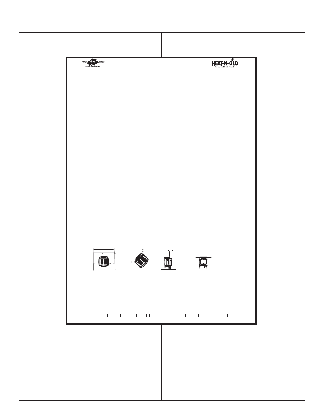
MINIMUM CLEARANCES TO COMBUSTIBLES / ESPACE MINIMUM AUX COMBUSTIBLES
Minimum clearances required from combustible construction for all appliance surfaces. / Espaces minimum exigés de la construction combustible aux surfaces de l’appareil.
A. Side of stove top to side wall 6" (152mm) Du coté du poêle au coté du mur
B. Rear of stove to back wall 0" (0 cm) Le contrôle arrière au mur arrière
C.Corner of stove top to side wall -Left 1" (25mm) Du coin arrière du poêle au mur de coté gauche
C. Corner of stove top to side wall-Right (for valve access) 3-1/2" (89mm) Du coin du dessus du poêle au mur de coté droit (acces a la valve)
D. Minimum Alcove Height 43" (1092mm) Hauteur minimum du plancher au plafond
E. Maximum Alcove Depth 36" (914mm) Profondeur maximum de l'alcove
F. Minimum Alcove Width 30" (762mm) Largeur minimum de l'alove
G. Mantle clearance from stove top 21-1/2"(546mm) Espace libre du poêle au manteau
HEARTH: A non-combustible hearth pad is not required. However, the floor beneath the stove must be stable, level, and strong enough to support the stove without a tipping hazard.
CHEMINÉE: Un
coussinet non-combustible de cheminée n’est pas exigé. Cependant, le plancher en dessous du poêle doit être droit, à niveau et assez fort pour supporter le poêle sans le hasard de basculer.
Date of Manufacture / Date du Manufacturier
2002 2003 2004 Feb Mar Apr May Jun Jul Aug Sep Oct Nov DecJan
DO NOT REMOVE THIS LABEL / NE PAS ENLEVER L’ TIQUETTE
Made in U.S.A. / Fait Aux
États-Unis
250-7481
A
A
A division of Hearth Technologies Inc.
20802 Kensington Boulevard, Lakeville, MN 55044
This appliance must be instal led in accordance with the cur rent Stan dard CAN/ CSA Z240 MH, Mobile Ho using or CAN/CSA Z240 RV, Recreational Vehicles, or with
Manufactured Home Construction and Safety Standard, Title 24 CFR, Part 3280, or when such standard is not applicable, ANSI/NCSBCS A225.1/NFPA 501A, Manufactured
Home Installation Standard, or with the ANSI A119.2/NFPA 501C, Standard for Recreational Vehicles.
WARNING: Do not operate the appliance until all sections have been assembled and installed in accordance with the manufacturer's instructions.
Installer l'appareil selon la norme CAN/CSA-Z240, Serie MM, Maisons mobiles ou CAN/CSA-Z240 VC Vehicules de camping, ou la norme 24 CFR Part 3280, Manufactured
Home Construction and Safety Standar d. Si ces normes ne sont pas pertineut es, utilisez la norme ANSI/NCSBCS A225.1/NFPA 501 A, Manufactured Home Installation s
Standard, ou ANSI A119.2 ou NFPA 501C Standard for Recreational Vehicles.
AVERTISSEMENT: Ne pas utiliser l'appareil tant que toutes les sections n'ont pas ete assemblees et installees selon les instructions du fabricant.
For use with Natural Gas For use with Propane
Usage Au Gaz Naturel Usage Au Gaz Propane
0-2000’ 0-2000’
Input Rate on “HI” (BTU/Hr) 17,500 16,000 Puissance Évaluée à “HI” (BTU/Hr)
Input Rate on “LO” (BTU/Hr) 11,500 12,000 Puissance Évaluée à “LO” (BTU/Hr)
Maximum Output (BTU/Hr)** 14,500 13,500 Puissance Maximum (BTU/Hr
Main Burner Orifice .078 .0469 Orifice du Brûleur Principal
Minimum Inlet Pressure (Inches W.C.)
4.5” 11”
Pression Minimum de la Valve (pouces W.C.)
Maximum Inlet Pressure (Inches W.C.)
7.0” 14”
Pression Maximum de la Valve (pouces W.C.
)
Manifold Pressure on “HI” (Inches W.C.)
3.5” 10”
Pression du Collecteur d’ Échappement à
“HI” (pouces W.C.)
**Max Venting, Blower On ** Ventilation Maximum, Ventilateur Allumé
This appliance equipped only for altitudes 0-2000’ (0-610m) in USA; and in Canada for altitudes of 0-4500’ (0-1370m). In USA for Altitudes above 2000’, the vent configuration,
orifice, or combination of both may need to be changed. See Owner’s Manual for information on making these changes.
This appliance must be installed in accordance with local codes, if any (and Commonwealth of Massachusetts approved); if none, follow National Fuel Gas Code ANSI
Z223.1, or Canadian Installation Codes, CAN/CGA-B149 in Canada. Install and use only in accordance with manufacturer’s installation and operating instructions.
Cet appareil est équipé pour les altitudes de 0-2000’ (0-610m) aux États-Unis; et au Canada pour les altitudes de 0-4500’ (0-1370m). Pour les altitudes au dessus de 2000’ aux
États-Unis, la configuration du ventilateur, son orifice ou les deux peuvent possiblement avoir à être changé. Voyez le manuel du propriétaire pour les informations sur ces
changements.
Cet appareil doit être installé en accord avec les codes locaux, s’il-y-a lieu(et approuvé par dans la République de Massachusetts); sinon lisez au National Fuel Gas Code
ANSI Z223.1, ou aux code courant d'installation Installez et utilisez en accords avec les instructions d’installation et d’opération du manufacturier.
Keep burner and control compartment clean. See installation and operating instructions accompanying this appliance. This vented gas fireplace heater is not for use with air filters.
Due to high surface temperatures, keep children, clothing and furniture away. Gardez le brûleur et le compartiment de contrôle propres. Vérifiez les instructions d’installation et
d’opération qui accompagnent cet appareil. Cet appareil de chauffage au gaz n’est pas pour l’usage avec des filtres d’air. Du aux surfaces de températures élevées, gardez les
enfants, les vêtements et les meubles à distance éloignée.
C
1
Left
Right
A
B
E
A
"A" measurement is from
stove top, not side
C
2
D
G
F
NUMÉRO DE SÉRIESERIAL LABEL
(Attached to stove with beaded chain)
(Étiquette attachée au poêle par une chaînette
à boules)
NOTE: HEARTH: A non-combustible hearth pad is not
required. However, the oor beneath the stove must be
stable, level, and strong enough to support the stove without
a tipping hazard. Wood ooring, ceramic tile, brick hearths,
or high pressure laminate ooring applied directly over the
sub-ooring material meet this requirement. If the appliance
is installed over carpet or combustible tile (vinyl tile), a metal
or wood panel extending the full width and depth of the
appliance must be installed.
Page 5
REMARQUE: ÂTRE: Un revêtement non-combustible en terre n’est pas
nécessaire. Cependant, le sol sur lequel repose le poêle doit être stable,
de niveau et sufsamment résistant pour supporter le poêle sans risque
de basculement. Un plancher en bois, un carrelage en céramique ou en
briques de terre cuite, ou encore un plancher stratié haute pression,
appliqués directement sur le sous-plancher, répondent à ces exigences.
Si l’appareil est installé sur un tapis ou sur un revêtement inammable
(en vinyle par exemple), vous devez installer un panneau de bois ou
de métal dont la largeur et la profondeur excèdent les dimensions
de l’appareil.
250-7471 November 15, 2002
Page 6
Due to high temperatures, the appliance should
!
be located out of traffic and away from furniture
and draperies.
SAFETY NOTICES
Do not place clothing or other flammable items
!
on or near the appliance at any time. Due to
thermostatic control, the possibility exists for the
appliance to turn on, igniting any items on or
near it.
Children and adults should be alerted to the
!
hazards of high surface temperature and should
stay away to avoid burns or clothing ignition.
Young children should be carefully supervised
!
when they are in the same room as the
appliance.
Any safety screen or guard removed for servicing
!
an appliance must be replaced prior to operating
the appliance
Installation and repair should be performed by a
!
qualified, and/or where required by state and local
codes, licensed installer/service technician. (In
the Commonwealth of Massachusetts, installation
must be performed by a licensed plumber or
gas fitter.) The appliance should be inspected
before use and at least annually by a professional
service person. More frequent cleaning may be
required due to excessive lint from carpeting,
bedding material, et cetera. It is imperative that
control
passagways of the appliance be kept clean.
Strict adherence to the instructions in this manual
!
must be followed. Improper installation will void
the warranty and safety listing.
This appliance is manufactured to operate on
!
natural gas (NG). It is field convertible to liquid
propane (LP) with the manufacturer's conversion
kit, available from your local Heat-N-Glo dealer.
Burning incorrect fuel voids the warranty and
safety listing and may cause an extreme safety
hazard.
compartments, burners and circulating air
CONSIGNES DE SÉCURITÉSAFETY NOTICES
À cause de la température élevée qu’il peut atteindre,
!
l’appareil ne doit pas être situé dans un endroit
passant ni près de meubles ou de draperies.
Ne posez jamais de vêtements ni de produits
!
inammables sur l’appareil ou à proximité. En
raison du contrôle thermostatique, il est en effet
possible que l’appareil se mette en marche seul
et mette le feu à ces objets.
Les enfants et les adultes doivent être avertis des
!
dangers présentés par la forte température en surface
et doivent être tenus éloignés pour éviter d’être brûlés
ou pour que les vêtements ne prennent pas feu.
Les jeunes enfants doivent être étroitement surveillés
!
quand ils sont dans la même pièce que l’appareil.
Les écrans ou dispositifs de protection déplacés à
!
l’occasion de l’entretien de l’appareil doivent être remis
en place avant la mise en marche de l’appareil.
L’installation et la réparation doivent être effectuées
!
par une personne qualiée. (Dans la République
de Massachusetts, l’installation doit être effectuée
par un plombier ou un installateur d’appareils à
gaz agréé.) L’appareil doit être inspecté avant
sa mise en service et au moins une fois l’an par
un professionnel. Un nettoyage plus fréquent
peut être nécessaire en cas de présence trop
importante de peluches provenant des tapis,
des lits, etc. Il est impératif que le tableau de
commande, les brûleurs et les passages d’air
restent propres.
Les instructions de ce manuel doivent être suivies
!
à la lettre. Une installation inappropriée annule la
garantie et les homologations de sécurité.
Cet appareil est conçu pour fonctionner au gaz
!
naturel (GN). Vous pouvez toutefois le convertir
au propane grâce au nécessaire de conversion
fourni par le fabricant. L’utilisation de combustibles
inappropriés avec cet appareil annule la garantie
et les homologations de sécurité, et peut être à
l’origine d’accidents très graves, disponible chez
votre vendeur local Heat-N-Glo.
Contact local building officials to obtain a permit
!
and information on installation restrictions or
requirements in your locale. It is also important
to notify your homeowner’s insurance company
of the installation of this appliance as well.
The glass door assembly SHALL ONLY be
!
replaced as a complete unit, as supplied by the
gas replace manufacturer. NO SUBSTITUTE
material may be used.
Allow the appliance to cool before carrying out any
!
maintenance or cleaning.
250-7471 November 15, 2002 Page 6
Adressez-vous aux autorités locales du bâtiment
!
pour obtenir un permis, et connaître les restrictions
et exigences d’installation en vigueur dans votre
région. De même, il est important de signaler
l’installation de cet appareil à la compagnie
d’assurance de votre propriétaire.
Ne remplacer la porte en verre que comme un
!
tout, dans l’état où elle est livrée par le fabricant.
Ne pas utiliser de SUBSTITUT.
Laissez l’appareil refroidir avant de procéder à
!
son entretien ou de le nettoyer.
Page 7
SAFETY NOTICES (cont'd.)
CONSIGNES DE SÉCURITÉ (suite)
Do not use this appliance if any part has been
!
under water. Immediately call a qualified service
technician to inspect the appliance and to replace
any part of the control system and any gas
control which has been under water.
Do not store or use gasoline or other flammable
!
liquids in the vicinity of the appliance.
If the flame becomes sooty, dark orange in color,
!
or extremely tall, DO NOT operate
the appliance.
Contact your dealer and arrange for servicing
immediately.
DO NOT operate the appliance if it is not operating
!
properly in any manner. Contact your dealer for
assistance.
Open viewing glass for servicing only.
!
Operate the appliance in accordance with the
!
instructions contained in this manual.
If the main burners do not start correctly, turn the
!
gas off at the gas control valve and contact your
dealer for service.
DO NOT operate with glass cracked or broken.
!
N’utilisez jamais cet appareil si des pièces ont été
!
immergées. Appelez immédiatement un technicien
qualié pour qu’il inspecte l’appareil et remplace les
pièces du système de commande et de régulation du
gaz qui ont été mouillées.
Ne gardez pas et n’utilisez pas d’essence ni d’autres
!
substances liquides inflammables à proximité de
cet appareil.
Si la amme dégage de la suie, devient de couleur
!
orange foncé ou est très grande, NE faites PAS
fonctionner l’appareil Contactez le vendeur pour faire
procéder à un entretien immé diat.
NE mettez PAS l’appareil en service s’il ne fonctionne
!
pas adéquatement et ce, pour quelque raison que ce
soit. Contactez le vendeur pour toute assistance.
!
N’ouvrez l’écran vitré que pour l’entretien.
Utilisez cet appareil conformément aux instructions
!
contenues dans ce manuel.
Si les brûleurs principaux ne s’allument pas correctement,
!
fermez le gaz ainsi que la soupape de contrôle du
gaz et demandez au vendeur qu’il fasse procéder à
un entretien.
N’utilisez jamais cet appareil si la vitre est ssurée
!
ou cassée.
This unit is not for use with solid fuel.
!
DO NOT place anything inside the firebox (other
!
than the included logs.)
If the logs become damaged refer to the
!
Parts and Accessories page of this manual for
replacement.
Instruct everyone in the house how to shut off
!
the gas to the appliance and also at the main
gas shut-off valve. The main gas shut-off valve is
usually located next to the gas meter or propane
tank and requires a wrench to shut off.
Use the built-in piezo igniter to light the
!
appliance.
DO NOT
!
DO NOT remove, replace, modify or
!
part of the appliance unless
use matches or any other
instructions are given
external device.
substitute
in this manual. All other work must be done by a
trained technician
The pilot flame must contact the thermopile and
!
thermocouple. If it does not, turn the gas control valve
to “OFF” and call your Dealer.
any
Cette unité de chauffage n’est pas conçue pour des
!
combustibles solides.
NE placez RIEN dans le foyer (mis à part les bûches
!
incluses).
Si les bûches sont détériorées, reportez-vous à la page
!
“ Pièces et accessoires “ de ce manuel pour obtenir
des informations sur leur remplacement.
Montrez à tous les membres de la maison comment
!
fermer l’arrivée de gaz sur l’appareil ainsi
robinet principal d’arrêt du gaz.
d’arrêt du gaz est habituellement situé à côté du
compteur à gaz ou de la cuve de propane; une clé est
nécessaire pour le fermer.
Utilisez le briquet piézoélectronique intégré pour
!
allumer l’appareil.
N’utilisez JAMAIS d’allumettes ni aucun autre dispositif
!
externe.
Vous NE devez JAMAIS enlever, replacer, modier
!
du remplacer des pièces de l’appareil si aucune
instruction n’est donnée à ce sujet dans ce manuel.
Toutes les autres opérations doivent être effectuées
par un technicien qualié.
La veilleuse doit être en contact avec la pile thermoélectrique
!
et le thermocouple. Si ce n’est pas le cas, fermez la
soupape de contrôle du gaz (position “OFF“) et appelez
le vendeur.
Le robinet principal
que sur le
Page 7
250-7471 November 15, 2002
Page 8

OVERVIEW OF INSTALLATION TO
OPERATION
PRÉSENTATION DE L’INSTALLATION ET
DU FONCTIONNEMENT
• Familiarize yourself with this Owner's Manual and the
Safety Notices located in this manual, and posted on the
gas appliance.
• Remove and unpack the following components:
The log set taped to the top of the stove.
Inside the firebox will be the component bag.
• Unbolt the appliance from the pallet.
• Remove the top and then the face of the stove. The face is
removed by lifting straight up.
• Remove the glass door by opening the latches located
on both the left and right sides at the top of the glass.
Pull towards you and separate latch from notches. Lift the
glass out of the two notches at its base and carefully set
aside.
• Convert to LP if necessary.
• Install Blower if purchased. (Part #GFK-75).
• Finalize your installation decisions and requirements:
• Refer to Dimensions on page 9.
• Refer to Clearances to Combustibles on page 9.
• Refer to Horizontal and Vertical termination
requirements on pages 23-31.
• Install damper if necessary for your venting plans, see
page 28.
• Refer to Vent Kits pertinent to your installation on
page 47.
• Contact your local building inspector for code requirements
in your area.
• Run thermostat lines to TH & TPTH connectors on valve,
if applicable, see page 14.
• Set unit in place and install venting per your installation
requirements.
• Install log set. See instructions on page 11-12 of this
manual.
• Connect the gas line. See page 34-35.
• Leak test gas line to manual shut-off valve. See page 36.
• Re-attach the glass door.
• Re-attach the face.
• Plug in blower, if purchased.
• Follow Lighting Instructions, page 37, to light the appliance.
(A copy is attached to a beaded chain on the lower right
hand side of the appliance).
• Adjust gas control knob to "ON" (Following Lighting
Instructions page 37).
• Set Thermostat or turn control panel switch to the "ON"
position.
• Check flames and adjust shutter position, if necessary.
See page 43.
• Familiarize yourself with the maintenance requirements of
the stove. See pages 41-42.
• Familiarize yourself with the Troubleshooting section of
this manual. See pages 45-46.
NOTE: In the Commonwealth of Massachusetts, the word
damper shall be replaced by the words ue restrictor.
• Lisez le manuel d’utilisation, ainsi que les consignes
de sécurité contenues dans ce manuel et apposées sur
l’appareil à gaz.
• Sortez et déballez les pièces suivantes:
Les bûches sont xées sur le dessus du poêle.
• À l’intérieur du foyer se trouvent le manuel d’utilisation et
un sac contenant les différentes pièces.
• Dévissez l’appareil de la palette.
• Sortez le haut puis la façade du poêle. Pour sortir la
façade, effectuez un mouvement vertical vers le haut.
• Sortez la porte vitrée en ouvrant les loquets situés à
gauche et à droite de la vitre, en haut. Tirez la vitre vers
vous et sortez les loquets de leur encoche à sa base, puis
mettez-la délicatement de côté.
• Procédez à la conversion au propane si nécessaire.
• Installez le ventilateur si vous l’avez. (Pièce n° GFK-75).
• Finalisez vos choix et vos besoins en matière d’installation:
• Reportez-vous aux dimensions, page 9.
• Reportez-vous aux dégagements aux combustibles,
page 9.
• Reportez-vous aux exigences en matière de sorties
verticales ou horizontales, pages 23-31.
• Installez le registre de tirage s’il est nécessaire à
plans de ventilation (reportez-vous à la page 28).
• Reportez-vous aux ensembles de ventilation qui
correspondent à votre installation, page 47.
• Adressez-vous à l’inspecteur du bâtiment local pour
connaître les exigences d’homologation en vigueur
dans votre région.
• Tirez les lignes de thermostat jusqu’aux connecteurs
TH & TPTH de la soupape, si applicable (reportez-vous
à la page 14).
• Mettez l’unité de chauffage en place et installez la
ventilation en fonction des besoins de votre installation.
• Installez les bûches. Repor tez-vous aux instructions
fournies à la page 11-12 de ce manuel.
• Branchez le tuyau de gaz. Reportez-vous aux pages
34-35.
• Vériez que le tuyau de gaz est parfaitement étanche
jusqu’au robinet d’arrêt manuel. Reportez-vous à la
page 36.
• Réinstallez la porte vitrée.
• Réinstallez la façade.
• Branchez la ventilation, si vous l’avez.
• Suivez les instructions d’allumage de l’appareil fournies à
la page 38. (Une copie est attachée par une chaînette sur
le côté inférieur droit de l’appareil).
• Positionnez le bouton de contrôle du gaz sur “ON“ (en
suivant les instructions d’allumage, page 38).
• Réglez le thermostat ou positionnez l’interrupteur du
panneau de contrôle sur “ON“.
• Surveillez les ammes et ajustez la position du volet, si
nécessaire. Reportez-vous à la page 43.
• Prenez connaissance des exigences d’entretien du poêle.
Reportez-vous aux pages 41-42.
• Prenez connaissance de la section Dépannage de ce
manuel. Reportez-vous aux pages 45-46.
REMARQUE: Dans le République de Massachusetts, l’amortisseur
de mot sera remplacé par le restricteur de conduite de cheminée
de mots.
vos
250-7471 November 15, 2002 Page 8
Page 9
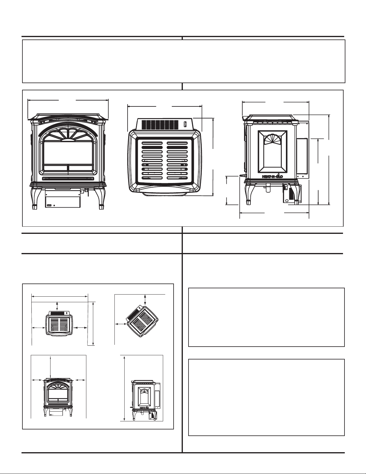
DIMENSIONS
18 - 1/8
16 - 13/16
46cm (18 1/8 PO)
42,7 cm
(16 13/16 PO)
18 - 1/8
46 cm (18 1/8 PO)
16 - 13/16
7 - 3/16
16 - 3/16
22 - 3/4
VERT FLUE
POS/POS.
VERT. DU
16 - 11/16
41,1 cm (16 3/16 PO)
57,7 cm
(22 3/4 PO)
42,4 cm
(16 11/16 PO)
18,2 cm
(7 3/16 PO)
42,7 cm (16 13/16 PO)
A
G -Alcove
A
D
C
1
Left
Right
A
B
F
E
A
"A" measurement is from
stove top, not side
C
2
Droite
Gauche
de l'alcôve
NOTE: Diagrams show gas stove equipped with optional Blower, Part #GFK-75.
REMARQUE: Les schémas décrivent un poêle à gaz équipé d’un ventilateur en option, pièce
n° GFK-75.
CLEARANCES TO COMBUSTIBLES
MINIMUM CLEARANCES TO COMBUSTIBLES
Minimum clearances required from combustible
all appliance surfaces.
construction for
DÉGAGEMENTS AUX MATÉRIAUX
COMBUSTIBLES
DÉGAGEMENTS MINIMUMS AUX MATÉRIAUX COMBUSTIBLES
Dégagements minimums nécessaires entre les surfaces combustibles
de la construction et celles de l’appareil.
A - Side of stove top to side wall..................6" (15.2cm)
B - Rear of stove to back wall ...................... 0" (0cm)
1 - Corner of stove top to side wall-Left ......1" (4.45cm)
C
2 - Corner of stove top to side wall-Right.... 3-1/2" (8.9cm)
C
D - Minimum alcove height.......................... 43" (109.2cm)
E - Maximum alcove depth.......................... 36" (91cm)
F - Minimum alcove width........................... 30" (76.25cm)
G - Top of stove to alcove ceiling ..................20-7/8" (53.3cm)
Page 9
A - Distance entre le haut du poêle et le mur latéral
B -
Distance entre l'arrière de poêle et le mur arrière
1 - Distance entre le coin supèrieur de poêle et le mur latéral gauche
C
(dégagement aménagé pour la soupape) ....................2,54 cm (1 po)
2 - Distance entre le coin supèrieur de poêle et le mur latéral droit
C
(dégagement aménagé pour la soupape) ...................8,9 cm (3.5 po)
D - Hauteur minimale de l'alcôve........................................ 109,2 cm (43 po)
E - Profondeur maximale de l'alcôve.................................91 cm (36 po)
F - Largeur minimale de l'alcôve .......................................76,25 cm (30 po)
G - Distance entre le haut du poêle et le plafond ..........................53,3 cm (20.98 po)
250-7471 November 15, 2002
.................
.................
15,2 cm (6 po)
0" (0 cm)
Page 10
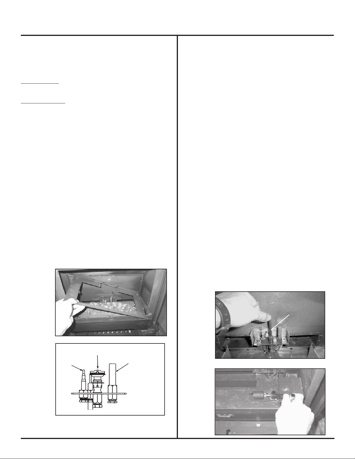
MILLIVOT GENERATOR
THERMOCOUPLE
PILOT HOOD
CAPUCHON DE LA VEILLEUSE
GÉNÉRATEUR DE MLLIVOTS
LP CONVERSION INSTRUCTIONS
INSTRUCTIONS POUR LA
CONVERSION AU PROPANE
NOTE: Gas conversions should only be performed by a
qualified service person, and/or where required by state
and local codes, licensed installer/service technician. In
the Commonwealth of Massachusetts, installation must be
performed by a licensed plumber or gas fitter.
KIT CONTENTS:
Replacement orice; replacement pilot injector;
valve regulator; conversion label.
TOOLS REQUIRED:
#2 phillips screwdriver, or slotted screwdriver,
or Torx TH20, 5/32" Allen wrench, or a 5/8" open end wrench.
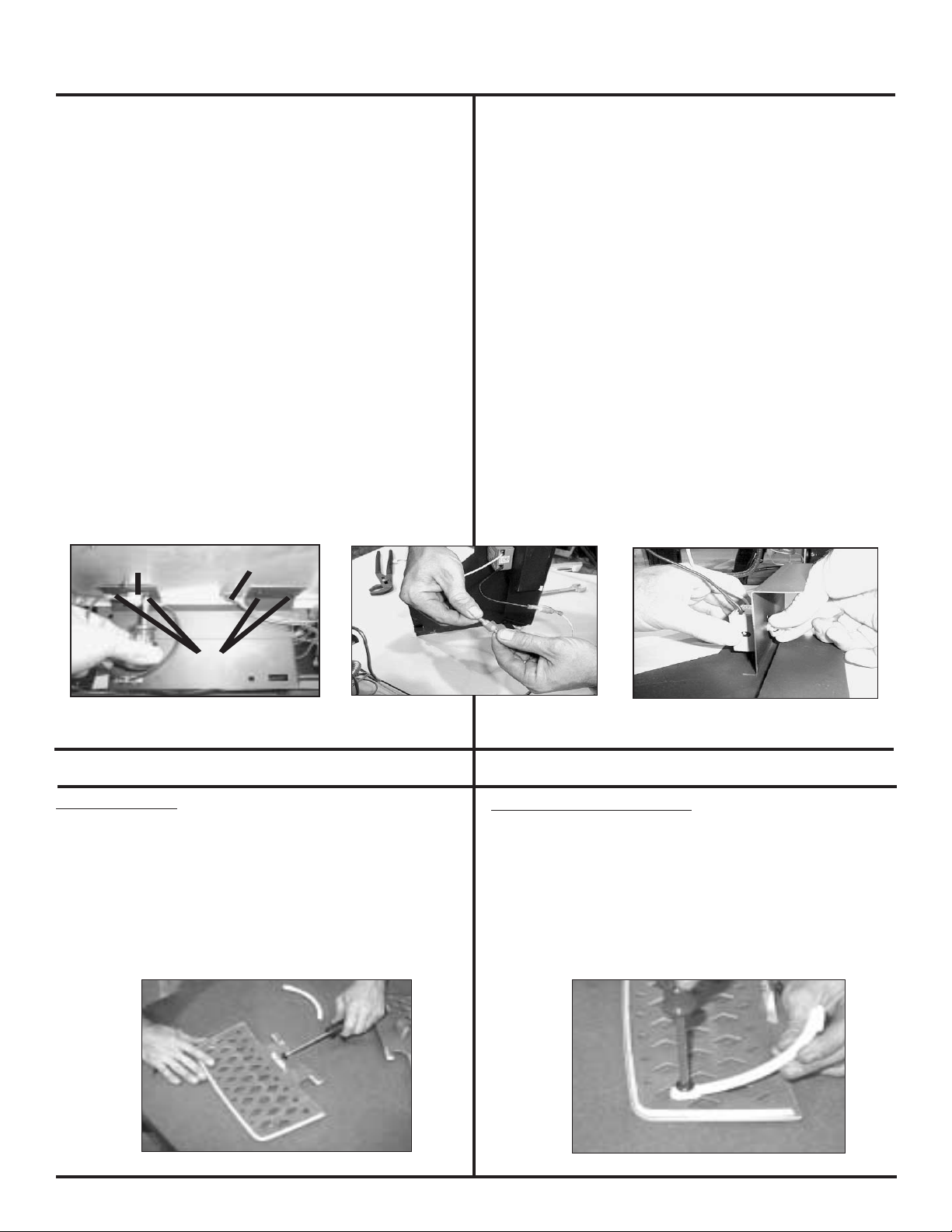
1. Remove front (if installed), glass, and logs (if installed.)
2. Remove log/burner pan: First remove screws then lift side of
pan vertically and pull out of rebox. (Fig. 1)
3. Remove burner: Loosen shutter set screw on the bottom of
the rebox and slide shutter all the way to the right (closed).
Lift left side of burner and slide to the left.
4. Pull off pilot hood and set aside. (Fig. 2)
5.
Use a 5/32" Allen wrench to remove the pilot injector. (Fig. 3)
6. Replace pilot injector with the one supplied with the stove
(#35 for Propane, #62 for Natural Gas).
7. Replace pilot hood, snapping into position.
8. Remove main burner orice using a 5/8" wrench.
9. Replace orice with the proper size as indicated below for
your gas type and venting. (Fig. 4)
PROPANE NATURAL GAS
.0469 .078
10. Reinstall burner. Slide burner neck into shutter and over orice.
Install log/burner pan using the three screws removed.
See page 11 for Valve Regulator Replacement.
REMARQUE: Les conversions de gaz devrait étre uniquement
exécutées par une personne qualiée, et/ou lorsque requis par des
codes d'Etats ou locaux, par un technicien d'installation/service
licencié. Dans la République de Massachusetts, l’installation doit
être effectuée par un plombier ou un installateur d’appareils à gaz
agréé.
L’ENSEMBLE COMPREND: Un orice de rechange; un injecteur de rechange
pour la veilleuse; un détendeur; une étiquette de conversion.
OUTILS NÉCESSAIRES: Un tournevis cruciforme n° 2 ou un tournevis pour
écrous à fente ou un tournevis Torx™ TH20 ou une clé Allen™ de 4 mm
(5/32 po) ou encore une clé à fourche de 15,87 mm (5/8 po).
1. Enlevez la façade (si installée), la vitre et les bûches (si installées).
2.
Enlevez le bac du brûleur/des bûches: retirez les vis, soulevez ensuite
le côté du bac à la verticale, puis tirez le bac vers l’extérieur du
foyer. (g. 1)
3. Enlevez le brûleur: Desserrer la vis de série de volet sur le fond de
volet de foyer et chute tout à la droite (ferme). Soulevez le côté
gauche du brûleur et faites-le glissez vers la gauche.
4. Retirez le capuchon de la veilleuse et mettez-le de côté. (g. 2)
5. Retirez l’injecteur de la veilleuse à l’aide d’une clé Allen de 4 mm (5/32
po). (g. 3)
6. Remplacez l’injecteur de la veilleuse par celui fourni avec le poêle
(n° 35 pour le propane, n° 62 pour le gaz naturel).
7. Replacez le capuchon de la veilleuse en veillant à bien l’emboîter.
8. Retirez l’orice du brûleur principal à l’aide d’une clé de 16 mm
(5/8 po).
9. Remplacez l’orifice par un autre de la taille appropriée à votre type
de ventilation et de gaz, tel qu’indiqué ci-dessous. (g. 4)
PROPANE 0,0469
GAZ NATUREL 0,078
10. Réinstallez le brûleur. Glissez la gorge du brûleur dans
le volet et par-dessus l’orice. Installez le bac du brûleur/des bûches
en utilisant les trois vis enlevées.
Fig. 1
Fig. 2
250-7471 November 15, 2002 Page 10
Reportez-vous à la page 11 pour le remplacement du détendeur.
5/32" Allen WrenchClé Allen de 4 mm
(5/32 po)
Fig. 3
Fig. 4
Page 11
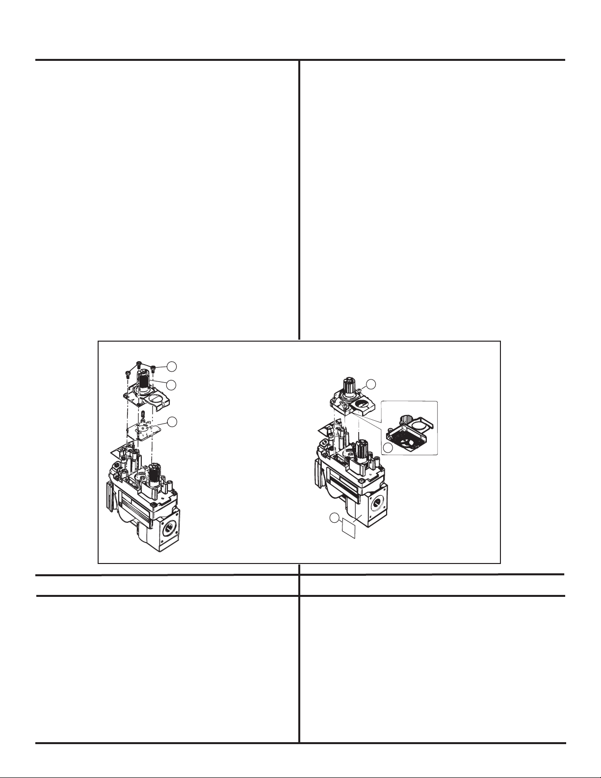
LP CONVERSION (cont'd.)
A
B
C
Mounting Screws
Vis retenant le détendeur
Pressure Regulator Tower
Colonne du détendeur
Diaphragm
Diaphragme
E
D
F
Rubber Gasket
Joint de caotchouc
Identification Label
Étiquette d'identification
New screws provided with kit
Nouvelles vis fournies avec
l'ensemble
CONVERSION AU PROPANE (suite)
Valve Regulator Replacement
1. Turn control knob to the OFF position, ensure that gas
supply to the valve has been turned off.
2. Using a Torx TH20, or slotted screwdriver, remove
the (A) three pressure regulator mounting screws, (B)
pressure regulator tower, and (C) diaphragm.
3. Ensure that the (D) rubber gasket is properly positioned
and install the new HI/LO pressure regulator assembly
to the valve using the (E) new screws supplied with
the kit. Tighten screws securely. (Reference torque
= 25 in/lb)
4. Install the enclosed (F) identication label to the valve
body where it can be seen.
5. Fill out the Conversion Label and attach to the valve
cover.
Remplacement du détendeur
1. Tournez le bouton de contrôle en position “OFF“ et
assurez-vous que la soupape d’alimentation du gaz
est fermée.
2. À l’aide d’un tournevis Torx TH20 ou d’un tournevis
pour écrous à fente, retirez les (A) trois vis retenant
le détendeur, la (B) colonne du détendeur et le (C)
diaphragme.
3. Assurez-vous que le (D) joint de caoutchouc est
positionné correctement et raccordez e nouveau
système de régulation de pressionà la soupape en
utilisant les (E) vis fournies avec l’ensemble. Serrez les
vis complètement. (Effort de serrage de référence =
63,5 cm/livre (25 po/lb)).
4. Collez l’étiquette (F) d’identification incluse sur la
soupape de sorte qu’elle puisse être visible.
5. Complétez l’étiquette de conversion et apposez-la sur
le couvercle de la soupape.
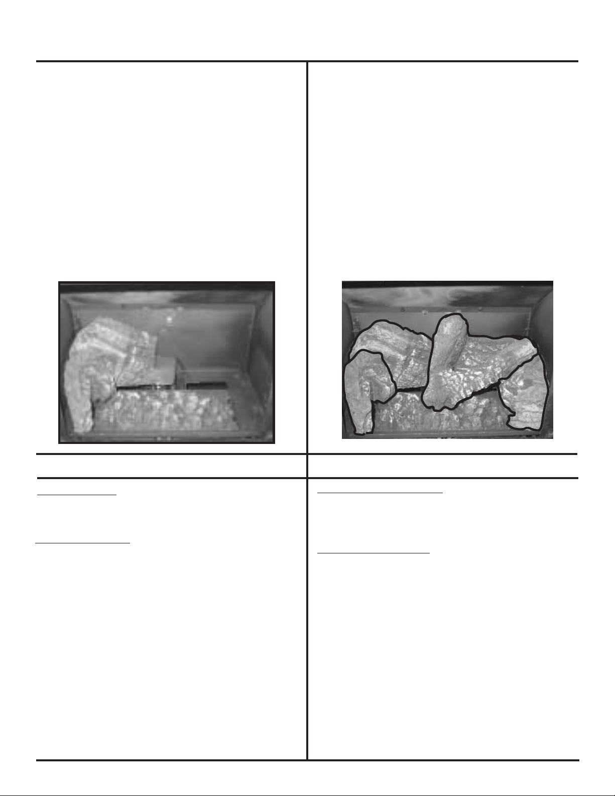
LOG SET INSTALLATION
The two piece log set is packed seperately and taped to
the top of the unit.
While breakable, the logs do not become fragile until after
the stove is burned and they have cured. After curing, any
handling must be done with care as breakage may occur
easily.
PLEASE NOTE: Logs have been designed to work
specifically with the burner of the Tiara Petite. Exact
placement will ensure proper operation of your gas
appliance and reduce sooting.
INSTALLATION DES BÛCHES
Les deux bûches sont emballées séparément et xées
sur le dessus de l’unité.
Bien qu’elles soient fragiles à l’origine, les bûches le
deviennent encore plus après leur durcissement (cuisson)
dans le poêle. Manipulez-les alors avec une grande prudence
car elles peuvent se briser facilement.
ATTENTION: Les bûches ont été spécialement conçues
pour le brûleur du modèle Tiara Petite. Leur positionnement
exact assure le bon fonctionnement de votre appareil à
gaz et réduit la formation de suie.
Page 11
250-7471 November 15, 2002
Page 12
LOG SET INSTALLATION (cont'd.)
INSTALLATION DES BÛCHES (suite)
Installation: Installation:
1. Gently remove top of unit and set aside.
2. Remove cast face by sliding straight up and set aside.
3. Remove the glass by releasing the two latches located
on the top of the stove. Lean glass frame forward and
lift out.
4. Place the left log into the far left corner of the rebox
as shown in Fig. 1.
5. Place the right log into the far right corner of the rebox
as shown in Fig. 2. The twig should lay gently on the
burner when installed properly.
Fig. 1
1. Retirez délicatement la partie supérieure de l’unité et
mettez-la de côté.
2. Retirez la surface en fonte en la faisant glisser vers le
haut. Mettez-la de côté.
3. Retirez la vitre en libérant les deux loquets situés sur
le dessus du poêle. Penchez le cadre de la vitre vers
l’avant et dégagez-le.
4. Placez la bûche gauche dans le coin arrière gauche du
foyer, comme l’indique la g. 1.
5. Placez la bûche droite dans le coin arrière droit du
foyer, comme l’indique la g. 2. La plus petite doit
reposer délicatement sur le brûleur si elle est installée
correctement.
Fig. 2
BLOWER INSTALLATION
KIT CONTENTS: Blower motor, housing and snap disc
assembly; rheostat (speed control); rheostat nut; knob;
screws; knob position label.
TOOLS REQUIRED: Short #2 Philips head screwdriver;
11/16" wrench.
The blower is held in place using 4-#6 screws. The
screws are already installed in the bottom of the
rebox.
If the appliance has not yet been installed you can lay
the appliance on it's back to install the blower. Make
sure the burner and the pan are in their proper place
after uprighting.
INSTALLATION DU VENTILATEUR
L’ENSEMBLE COMPREND: Le moteur du ventilateur; un
boîtier et un disque fermoir; un rhéostat (régulateur de
vitesse) et son écrou; un bouton; des vis; une étiquette pour
le positionnement du bouton.
OUTILS NÉCESSAIRES: Un tournevis cruciforme n° 2 à
tête courte, une clé de 17,5 mm (11/16 po).
Le ventilateur est maintenu en place à l’aide des 4 vis n°
6. Les vis sont déjà installées à la base du foyer.
Si l’appareil n’est pas encore en place, vous pouvez le
coucher sur le dos pour installer le ventilateur. Assurezvous que le brûleur et le bac sont bien positionnés une
fois l’appareil redressé.
250-7471 November 15, 2002 Page 12
Page 13
Mounting Screws
Snap Disc
Disque fermoir
Pilot tubes and wires
Tubes et fils de la veilleuse
Vis de montage
BLOWER INSTALLATION (cont'd.)
INSTALLATION DU VENTILATEUR (suite)
1. Remove the (4) screws from the rebox and slide the
blower into place from the left side of the stove.
Notice the locations of the pilot assembly tubes and
wires. The pilot tubes and wires may need to be moved
to prevent scraping the blower housing. (Fig. 1)
2
. Re-use the (4) screws removed from the bottom of the re-
box, to install the blower. Install the 2 screws on the right
rst, then use the other 2 screws to hold the snap disc in
place and support the left side of the blower. (Fig. 1)
3. Remove the valve access panel by removing the (3)
screws that secure it to the right side of stove and sliding
it out.
4.
Attach the rheostat to valve access cover and tighten
with 11/16 wrench. Attach label showing knob positions
on valve cover. Install the knob on the rheostat. (Fig. 2)
5. Connect the black and white wires from the blower to
the rheostat wires. (Fig. 3)
6. Re-install the valve access cover.
7. Route power cord away from unit. DO NOT route the
power cord under or in front of the stove.
1. Retirez les (4) vis du foyer et positionnez le ventilateur
en le faisant glisser par la gauche du poêle. Notez
l’emplacement des ls et tubes de la veilleuse. Vous
serez en effet peut-être amené à les retirer pour ne pas
abîmer le boîtier du ventilateur. (g. 1)
2. Réutilisez les (4) vis retirées de la base du foyer pour
installer le ventilateur. Placez deux vis à droite, puis
utilisez les deux autres pour maintenir le disque fermoir
en place et pour soutenir le côté gauche du ventilateur.
(g. 1)
3. Retirez le panneau d’accès aux soupapes: desserrez
les (3) vis qui le tiennent xé au côté droit du poêle et
dégagez-le en le faisant glisser.
4. Vissez le rhéostat sur le couvercle des soupapes à
l’aide d’une clé de 17,5 mm (11/16 po). Collez l’étiquette
indiquant les positions du bouton sur le couvercle de la
soupape. Installez le bouton sur le rhéostat. (g. 2)
5. Connectez les ls blancs et noirs du ventilateur aux ls
du rhéostat. (g. 3)
6. Réinstallez le couvercle d’accès aux soupapes.
7. Éloignez le câble d’alimentation de l’unité. NE le faites
JAMAIS passer en dessous ni devant le poêle.
Fig. 1
Fig. 2
WARMING SHELF INSTALLATION
KIT CONTENTS: (2) Warming shelves, (2) brackets, and
(4) 1/4" Phillip head screws.
1. Remove warming shelves and hardware from packaging.
2. Install leveling bolt to each warming shelf. See Fig. 1.
3. Install warming shelf bracket loosely to each warming
shelf using the bolt provided. See Fig. 2.
Fig. 1
Fig. 3
INSTALLATION DU RAYON CHAUFFANT
L’ENSEMBLE COMPREND: (2) Rayons chauffants, (2)
supports et (4) vis cruciforme à tête de 6,3 mm (1/4 po).
1. Sortez les rayons chauffants et le matériel de
l’emballage.
2. Installez les boulons de mise à niveau sur chaque rayon
chauffant. (g.1)
3. Fixez les supports sur les rayons chauffants sans trop
serrer les boulons fournis. (g.2)
Fig. 2
Page 13
250-7471 November 15, 2002
Page 14
WARMING SHELF INSTALLATION (cont'd.)
INSTALLATION DU RAYON
CHAUFFANT (suite)
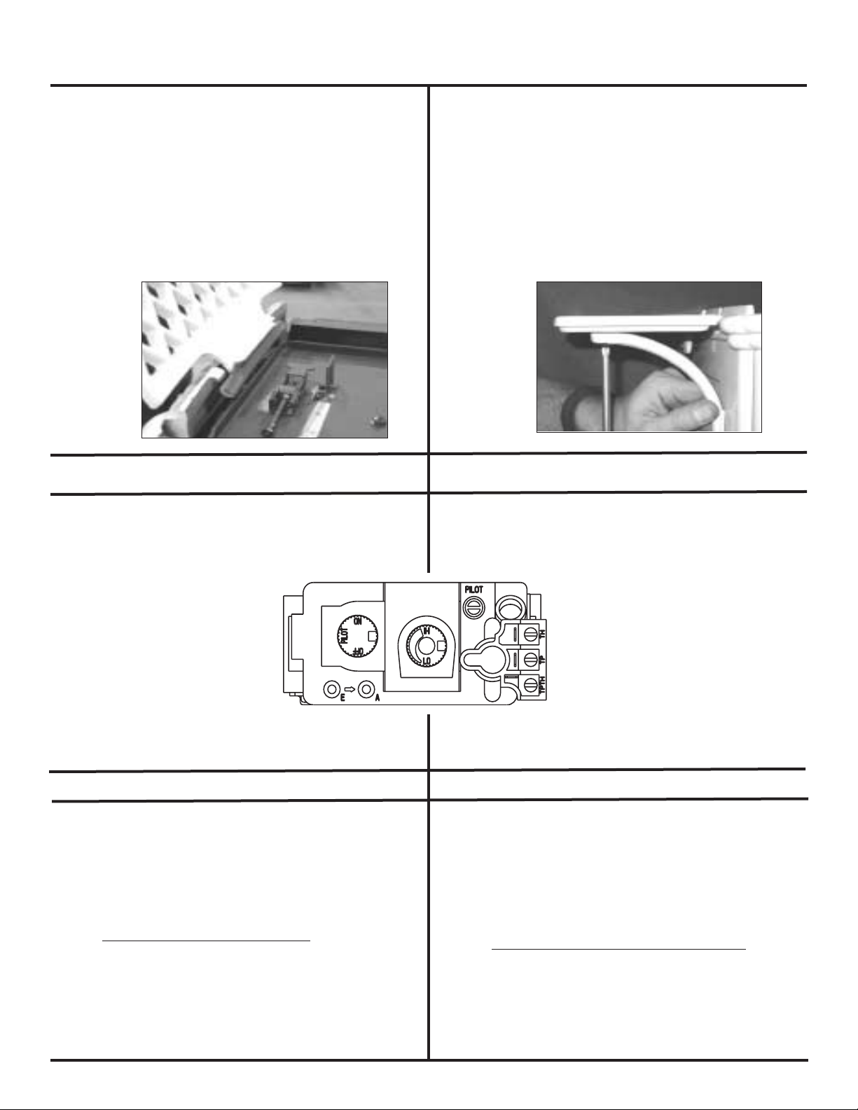
4. Gently lift cast top off of unit and set aside.
5. Install warming shelf to unit gently aligning the shelf
with the tabs that are in place on the side of the unit.
Use the leveling bolt in the located in the center of
the warming shelf to adjust the shelf to it's desired
position. See Fig. 3.
6. Align bracket to rebox and gently tighten the screw to
hold it in place. See Fig. 4.
7. Reassemble the appliance.
Fig. 3
THERMOSTAT INSTALLATION
A thermostat may be installed to regulate the Tiara Petite. It is
important to use a thermostat designed for millivolt operation.
Do not connect the heater to a thermostat serving any other
appliance. Bedroom installation in
Canada requires this heater to be
connected to a thermostat.
Connect the thermostat wires to
the outside valve terminals labeled
"TH" and "TPTH". Turn the manual
switch on the control panel to
"OFF".
4. Sortez délicatement le dessus en fonte de l’unité et
mettez-le de côté.
5. Installez le rayon chauffant dans l’unité en l’alignant
délicatement avec les languettes situées sur les côtés
de l’unité. Utilisez le boulon de mise à niveau situé
au centre du rayon chauffant pour positionner le rayon
correctement. (g.3)
6. Alignez le support avec le foyer et vissez-le délicatement
pour le maintenir en place. (g. 4)
7. Réassemblez l’appareil.
Fig. 4
INSTALLATION DU THERMOSTAT
Un thermostat peut être installé pour réguler le modèle Tiara
Petite. Il est important d’utiliser un thermostat conçu pour
fonctionner en millivolts. Ne branchez pas le chauffage à un
thermostat servant pour d’autres
appareils. Au Canada, l’installation
dans une chambre à coucher implique que le chauffage soit connecté
TH
TPTH
à un thermostat.
Connectez les ls du thermostat aux
bornes extérieures de la soupape
étiquetée “TH“ et “TPTH“. Tournez
l’interrupteur manuel du panneau de
contrôle en position “OFF“.
REMOTE CONTROL
A remote control or a wall switch may be wired to the
thermostat terminals. Contact your Dealer for details.
Recommended Maximum Lead Length (2 wire) when using
wall thermostat/switch:
Wire Size Maximum Length
16 gauge 65 Feet
18 gauge 40 feet
20 gauge 25 feet
22 gauge 18 feet
250-7471 November 15, 2002 Page 14
Une commande à distance ou un interrupteur mural peuvent
être reliés aux bornes du thermostat. Adressez-vous au
vendeur pour plus de détails
Longueur de câble maximale recommandée (2 ls) en cas
d’utilisation du thermostat avec un interrupteur mural:
Épaisseur du l Longueur Maximum
Calibre 16 20 m (65 pi)
Calibre 18 12 m (40 pi)
Calibre 20 7,50 m (25 pi)
Calibre 22 5,50 m (18 pi)
COMMANDE À DISTANCE
Page 15

GENERAL VENTING INSTRUCTIONS
INSTRUCTIONS GÉNÉRALES SUR LE
VENTILATEUR
PLEASE NOTE: In order to comply with applicable
codes and product warranties, only SL-D series, Simpson
Dura-Vent (SDV) or Hearth & Home Technologies venting
components may be used. DO NOT USE FIELDFABRICATED VENTING COMPONENTS. The Tiara Petite
is approved to be vented either horizontally, through the side
wall, or vertically, through the roof. You may vent through a
Class A or masonry chimney if an approved adapter is used
(for USA installations only). Only use components labeled
and listed on pages 47-48.
This appliance is a direct vent heater. All combustion air
must come directly from the outside of the building. The
vent pipe for this unit consists of an inner and an outer
pipe. The inner pipe carries the stove exhaust out of the
system, and the outer pipe brings fresh combustion air into
the stove.
! A wall thimble is required when the venting passes
through a wall.
! A support box or firestop is required when the venting
passes through a ceiling.
! Roof flashing and a storm collar are required when
venting passes through the roof. Follow instructions provided
with the venting for installation of these items.
IMPORTANT: Read all these instructions carefully before
starting the installation. Failure to follow instructions
may create a fire or other safety hazard, and will
void the warranty. Be sure to follow these installation
instructions for venting and clearance to combustible
requirements, which may vary from one installation to
another. Do not extend the venting system in excess
of the distance prescribed in these manufacturer’s
installation instructions. This gas appliance must not
be connected to a chimney flue serving a separate
solid-fuel burning appliance.
INSTALLATION PRECAUTIONS:
The Heat-N-Glo Tiara Petite is an engineered product
that has been designed and tested. The warranty will be
voided, and serious fire, health, or other safety hazards may
result from any of the following actions: Installation of any
damaged venting component, unauthorized modification of
the venting system, installation of any component part not
approved by Hearth & Home Technologies, or installation
other than as instructed by these instructions. Consult your
local building codes before beginning this installation.
ATTENTION: Pour que votre installation soit conforme à la
réglementation applicable et aux garanties du produit, vous
ne devez utiliser que des éléments de ventilation directe
de la série SL-D, de marque Dura-Vent (SDV) ou Hearth
Technologies Inc. (HTI). N’UTILISEZ JAMAIS DE PIÈCES
TROUVÉES SUR PLACE. Le modèle Tiara Petite est
homologué pour être ventilé soit horizontalement, à travers
le mur, soit verticalement, à travers le toit. La ventilation
peut être réalisée par le biais d’une cheminée de Classe
A ou d’une cheminée en maçonnerie à condition d’utiliser
un adaptateur Simpson Dura-Vent (pour les installations
aux États-Unis uniquement). Utilisez uniquement les pièces
directe homologuées et répertoriées aux pages 47-48.
Cet appareil est un chauffage à évacuation directe. La
totalité de l’air comburant doit directement provenir de
l’extérieur du bâtiment. La conduite de ventilation de cette
unité est constituée d’un tuyau interne et d’un tuyau externe.
Le premier évacue les gaz émis par le poêle, et le second
alimente le poêle en air comburant.
! Une gaine murale pour tuyau de faible diamètre
est nécessaire lorsque le système ventilation traverse
un mur.
! Un boîtier de support ou un coupe-feu est nécessaire
lorsque le système de ventilation traverse le plafond.
! Lorsqu’il traverse le toit, un solin et un collier
évacuateur d’eau sont alors nécessaires. Suivez les instructions
fournies avec le système de ventilation pour procéder à
l’installation de ces éléments.
IMPORTANT: Veuillez lire attentivement l’intégralité de
ce manuel avant de procéder à l’installation. Le non
respect de ces instructions peut être à l’origine d’un
incendie ou d’autres dommages et entraîne la nullité de
la garantie. Veillez à bien suivre ces instructions pour
installer la ventilation et à respecter les dégagements
aux matériaux combustibles; ils peuvent varier d’une
installation à l’autre. Veillez à ce que le système de
ventilation n’excède jamais la longueur indiquée par
le fabricant dans ces instructions d’installation. Cet
appareil à gaz ne doit jamais être connecté à un conduit
de cheminée desservant un autre appareil brûlant des
combustibles solides.
PRÉCAUTIONS D’INSTALLATION:
Le modèle Tiara Petite de Heat-N-Glo est un produit usiné
qui a été mis au point et testé. Les actions suivantes peuvent
causer un incendie, nuire à votre santé ou se révéler très
dangereuses; elles peuvent également rendre la garantie
inapplicable: installation d’une pièce endommagée, modication
non autorisée du système de ventilation, installation d’une pièce
non approuvée par Hearth & Home Technologies. ou installation
non conforme à ces instructions. Reportez-vous aux normes de
construction avant de commencer l’installation.
Page 15
250-7471 November 15, 2002
Page 16
GENERAL VENTING INSTRUCTIONS (cont'd.)
INSTRUCTIONS GÉNÉRALES SUR LE
VENTILATEUR (suite)
WARNING: Always maintain the required clearances (air
space) to nearby combustibles to avoid creating a fire hazard.
Do not fill air space with insulation. Minimum clearance
between vent pipes and combustible surfaces is 1” (2.5cm).
Be sure to check the horizontal vent termination clearance
requirements from decks, windows, soffits, gas regulators,
air supply inlets and public walkways, as specified on page
23 of these installation instructions, the vertical termination
requirements on pages 20-22 and 30, and local building
codes.
The gas heater and vent system must be vented directly
to the outside of the building, and never be attached to
a chimney serving a separate solid fuel or gas-burning
appliance. This direct vent gas fireplace must use its
own separate vent system. Common vent systems are
prohibited.
INSTALLATION METHODS & NOTES
ATTENTION: Veillez à toujours respecter les dégagements
(espaces d’air) requis par rapport aux matériaux
combustibles avoisinants de façon à éviter tout risque
d’incendie. Ne remplissez pas ces espaces de matières
isolantes. L’espace minimum requis entre la conduite de
ventilation et toute surface combustible est de 2,5 cm (1
po). Respectez scrupuleusement les dégagements des
sorties d’évent horizontales par rapport aux planchers,
fenêtres, softes, détendeurs de gaz, arrivées d’air et
passages, spéciés à la page 23 de ces instructions
d’installation. Respectez également les dégagements
requis au niveau des sorties verticales (pages 20-22 et
30) et vériez les normes de construction locales.
Le chauffage au gaz et le système de ventilation doivent
être raccordés à l’extérieur du bâtiment directement; ils ne
doivent jamais être raccordés à une cheminée desservant un
appareil de chauffage à gaz ou à combustible solide. Ce foyer
à gaz à évacuation directe doit utiliser son propre système
de ventilation. Les systèmes de ventilation ordinaires sont
rigoureusement interdits.
MÉTHODES ET REMARQUES
D’INSTALLATION
Four types of direct vent system installations are
approved for use with the Tiara Petite.
1. Horizontal Termination (Fig. 1, page 21)
2. Vertical Termination (Fig. 2, page 21)
3. Into a Class A Metal Chimney (Fig. 3, page 21) USA
installations only
4. Into a Masonry Chimney (Fig. D, page 22) USA
installations only
Do not connect to a chimney serving a separate solidfuel burning appliance.
In each of these installation methods, it is very important
to maintain a balance between the combustion air intake
and the flue gas exhaust venting system.
Note: Certain limitations as to vent and vertical termination
configurations apply, and must be strictly adhered to.
When planning your installation, it is necessary to select the
proper length of vent pipe for your particular requirements.
Quatre types d’installations de système à évacuation
directe sont approuvés pour le modèle Tiara Petite.
1. Sortie horizontale (g. 1, page 21)
2. Sortie verticale (g. 2, page 21)
3. Dans une cheminé métallique de Classe A (g. 3, page
21) pour une installation aux États-Unis seulement.
4. Dans une cheminée en maçonnerie (g. D, page 22)
pour une installation aux États-Unis seulement.
Ne raccordez jamais cette unité à une cheminée desservant
un appareil de chauffage à combustible solide.
Pour chacune de ces méthodes d’installation, il est très
impor tant de maintenir l’équilibre entre l’arrivée d’air
comburant et l’évacuation des gaz par le système de
ventilation.
Remarque: Certaines restrictions doivent être scrupuleusement respectées selon la conguration des sorties verticales
et de la ventilation.
Lors de la planication de l’installation, il est nécessaire
de prévoir la longueur appropriée de tuyau de ventilation
dont vous aurez besoin.
250-7471 November 15, 2002 Page 16
Page 17

INSTALLATION METHODS & NOTES (cont'd.)
MÉTHODES ET REMARQUES
D’INSTALLATION (suite)
1. For installations with any horizontal vent run or horizontal
termination, refer to the Vent Graph on pages 26-27.
This graph will show the relationship between vertical and
horizontal side wall venting, and help you to determine the
amount of vertical rise necessary for “vertical-to-horizontal”
type installations. NOTE: Be sure to take into consideration
the wall thickness when calculating your venting needs.
2. To determine the length of pipe required for vertical
installations, measure the distance from the stove flue outlet
to the ceiling, the ceiling thickness, the vertical rise in an attic
or second story, and allow for sufficient vent height above
the roofline. Refer to the vertical vent termination tables on
page 22 for this information. For two-story applications, fire
stops are required at each floor level. If an offset is needed in
the attic, additional pipe and elbows will be required. When
determining the position of the stove, be sure to adhere to
minimum clearance to combustibles to the appliance itself.
(See page 9, Minimum Clearances to Combustibles.)
3. When installing this appliance into an existing masonry
chimney, it is important to carefully measure the length
of flex needed to reach from the appliance outlet to the
termination cap. If the flex length is too short, a flex coupler
will be needed to attach an additional length of flex liner to
make up the difference. If the flex length is too long, the liner
could sag below the appliance outlet, which could result in
an airflow restriction causing flow reversal or flame lift.
SAFETY PRECAUTIONS FOR THE INSTALLER
Wear gloves and safety glasses for protection when installing
this stove. Exercise extreme caution when using ladders
or on rooftops around power lines. Be aware of electrical
wiring locations in walls and ceilings.
1. Dans le cas d’installations impliquant une conduite de
ventilation horizontale ou une sortie horizontale, reportezvous au schéma illustrant le système de ventilation, pages
26-27. Ce graphique explique le rapport entre la ventilation
verticale et horizontale par le mur latéral, et vous aidera à
déterminer la hauteur nécessaire pour des installations
de type “vertical-horizontal“. REMARQUE: N’oubliez pas
de prendre en considération l’épaisseur du mur quand
vous calculez la longueur des conduites de ventilation
nécessaire.
2. Pour déterminer la longueur de tuyau nécessaire à une
installation verticale, mesurez la distance entre la buse
du poêle et le plafond, ajoutez l’épaisseur du plafond et la
hauteur de plafond d’un grenier ou d’un second étage, et
prévoyez une hauteur de ventilation sufsante au-dessus du
faîtage du toit. Pour obtenir ces renseignements, reportezvous aux tableaux des sorties d’évent verticales, page 22.
Dans le cas d’installations dans des bâtiments de deux
étages, des coupe-feux sont nécessaires à chaque étage.
Si une déviation est nécessaire dans le grenier, des tuyaux
et des coudes additionnels sont à prévoir. Au moment
de déterminer la position du poêle, veillez à respecter
les dégagements minimums requis entre le poêle et les
matériaux combustibles (reportez-vous à la page 9, Les
dégagements minimums à combustibles).
3. Si vous raccordez cet appareil à une cheminée en maçonnerie préexistante, il est important de mesurer exactement
la longueur de tuyau exible nécessaire entre la sortie de
l’appareil et le capuchon d’évent. Si cette longueur est
insufsante, vous devrez utiliser un coupleur exible pour xer
une autre longueur de tuyau et combler ainsi la différence. Si
le tuyau exible est trop long, il peut pendre sous la sortie de
l’appareil, risquant ainsi de réduire le tirage et de causer des
retours de fumées ou le refoulement des ammes.
CONSIGNES DE SÉCURITÉ CONCERNANT
L’INSTALLATEUR
HTI DV WALL THIMBLE
Part# HTI-DV-WT
BEFORE YOU BEGIN:
Venting conguration will determine which Trim Ring you
use in your installation. Review Figures A, B and C on
Page 20. Figures A and B can use either Trim Ring, while
Figure C REQUIRES the Ventilated Trim Ring.
Page 17
Portez des gants et des lunettes de protection lors de
l’installation du poêle. Soyez tout particulièrement prudent si
vous utilisez une échelle ou si vous vous trouvez sur le toit à
proximité des lignes électriques. Repérez l’emplacement des
ls électriques dans les murs et les plafonds.
GAINE MURALE HTI DV POUR TUYAU
DE FAIBLE DIAMÈTRE HTI-DV-WT
AVANT DE COMMENCER:
La conguration de la ventilation déterminera la rondelle
décorative à utiliser pour votre installation. Revenez aux
figures A, B et C, page 20. Des rondelles décoratives
peuvent être utilisées dans les gures A et B alors que la
rondelle ventilée est indispensable dans la gure C.
250-7471 November 15, 2002
Page 18

HTI DV WALL THIMBLE (cont'd.)
GAINE MURALE HTI DV POUR TUYAU
DE FAIBLE DIAMÈTRE (cont'd.)
ASSEMBLING SLIM LINE TRIM RING & HEAT SHIELD
1. Choose the appropriate Trim Ring for your installation.
Lay on at surface and bend up the 6 welded brackets into
a 90 degree position. The brackets along the outer edge
of the ring are for locating the ring in the center of the hole.
See Fig. 1.
2. The Heat Shield is shipped at and must be hand
bent into a half circle before attaching to Trim Ring. Bend
Heat Shield. See Fig. 2.
Note: Wear leather gloves when bending the Heat Shield
to prevent injury.
3. Attach the Heat Shield to the Trim Ring with the four
screws provided. Screws go through the Heat Shield and
into the brackets on the Trim Ring. See Fig. 3, Page 19.
Fig. 1 Solid Trim Ring Shown
Fig. 1 Illustration de la rondelle décorative pleine
ASSEMBLAGE DE LA RONDELLE DÉCORATIVE DU
TUYAU À FAIBLE DIAMÈTRE et de l’ÉCRAN THERMIQUE
1. Choisissez la rondelle décorative appropriée à votre
installation. Posez-la sur une surface plate et relevez à
90 degrés les 6 attaches soudées. Ces attaches, situées
sur le pourtour de la rondelle, permettent de centrer la
rondelle sur le trou (g. 1)
2. L’écran thermique est livré à plat ; vous devez le
plier manuellement en demi-cercle avant de le xer à la
rondelle décorative. Pliez l’écran thermique (g. 2).
Remarque: Pour ne pas vous blesser, portez des gants
de cuir pour plier l’écran thermique.
3. Fixez l’écran thermique à la rondelle décorative
avec
les quatre vis fournies. Les vis traversent l’écran et
passent dans les attaches situées sur la rondelle décorative
(g. 3, page 19).
Fig. 2 Bending Heat Shield
Fig. 2 Pliage de l’écran thermique
INSTALLING TRIM RING and HEAT SHIELD
1. Measure from oor to center line of the vent pipe. Cut
out a 9-1/2" hole in the wall. Hold the Trim Ring/Heat
Shield Assembly in place and place a mark on the shield
with a black marker where it protrudes through the exterior
wall. See Fig. A on Page 20.
2. Use that mark as a guide to trim off excess Heat
Shield with a pair of sheet metal shears.
250-7471 November 15, 2002 Page 18
1. Mesurez la distance séparant le sol de l’axe du tuyau
de ventilation. Découpez un trou de 24 cm (9-1/2 po)
dans le mur. Maintenez la rondelle décorative et l’écran
thermique en place, puis repérez au feutre noir le point
d’intersection entre l’écran et le mur extérieur (g. A,
page 20).
2. Aidez-vous de ce repaire pour découper la partie
superue de l’écran thermique à l’aide de cisailles à
tôle.
INSTALLATION DÉCORATIVE DU TUYAU
DE FAIBLE DIAMÈTRE et DE L’ÉCRAN
THERMIQUE
Page 19

HTI DV WALL THIMBLE (cont'd.)
3/4
3/4
3/4
INSTALLING TRIM RING
and HEAT SHIELD (cont'd.)
GAINE MURALE HTI DV POUR TUYAU
DE FAIBLE DIAMÈTRE (suite)
I
NSTALLATION DÉCORATIVE DU TUYAU DE
FAIBLE DIAMÈTRE et DE L’ÉCRAN
THERMIQUE (suite)
Note: When installing the Trim Ring/Heat Shield assem-
bly make sure the Trim Ring is centered in the hole and
that the shield is above the pipe. There must be a minimum of 3/4" minimum clearance maintained to combustibles from the top of the Heat Shield. See Fig. 4.
3. Ensure that framing on the inside of the wall is a minimum inner framing diameter of 10" x 10".
4. The four Trim Ring mounting screws provided should be
replaced with appropriate fasteners for stucco, brick, concrete, or other types of sidings.
Fig. 3 Ventilated Trim Ring Shown
Fig. 3 Illustration de la rondelle décorative ventilée
Remarque: lorsque vous installez la rondelle décorative
et l’écran thermique, assurez-vous que la rondelle est
bien centrée sur le trou et que l’écran couvre le tuyau.
Veillez à conserver un dégagement minimum de 2 cm
(3/4 po) entre les surfaces combustibles et la partie
supérieure de l’écran thermique (g. 4).
3. Assurez-vous que le diamètre interne de l’encadrement
aménagé dans le mur soit de 25 cm x 25 cm (10 po x
10 po) au minimum.
4. Les quatre vis fournies avec la rondelle décorative
doivent être remplacées par des xations spéciques
lorsque vous percez du stuc, de la brique, du béton ou
d’autres types de revêtements.
Fig. 4 Maintain minimum 3/4" clearance to
combustibles from top of shield
Fig. 4 Conservez un dégagement minimum de 2
cm (3/4 po) entre les surfaces combustibles et la
partie supérieure de l’écran thermique.
Note: When installing the Tiara Petite to a rear wall in the
Zero Clearance conguration remove the two heat shield
knock-outs on the rear of the stove. See Fig. 5.
Fig. 5
Page 19
Remarque: Si vous installez le modèle Tiara Petite
sur le mur arrière dans une conguration ne requérant
aucun dégagement, retirez les deux broches destinées
à l’écran thermique qui se trouvent à l’arrière du poêle.
Reportez-vous à la g. 5.
250-7471 November 15, 2002
Page 20

90 DEG. ELBOW/
PIPE LENGTH/
Longeur de tuyau
PIPE LENGTH/
Longeur de
tuyau
SLK-01TRD (recommended for
optimum performance)/
Piéce SLK-01TRD
OR
HORIZONTAL TERMINATION
CAP, Simpson Dura Vent Part
#985/
OU CAPUCHON DE SORTIE
HORIZONTALE, PIÉCE N° 985
HEAT SHIELD
OVER PIPE/
MOITIÉ SUPÉRIEURE
FINIE DE ÉCRAN DE
THERMIQUE DE PIPE
Center Line/
Ligne centrale
TRIM RING
SOLID OR
VENTILATED/
L'ANNEAU
D'ÉQUILIBRE A AÉRÉ
REQUIS
Place mark where protrudes through exterior wall to cut
off excess/Placez la marque où le thermique de écran
dépasse par le mur extérieur pour découper l'excès
COUDE À 90
DEGRÉS
45° Elbow/
Coude à
45 degrés
1" Clearance from stove corner to combustible wall./
Dégagement de 1" avec le coin de fourneau au mur
combustible.
3-1/2" Clearance from stove
corner to combustible wall (for
valve access on right side)./31/2" dégagement avec le coin
de fourneau eau au mur
combustible (pour l'accès de
HEAT SHIELD OVER PIPE/
TRIM RING SOLID OR VENTILATED/
SOLIDE D'ANNEAU D'ÉQUILIBRE OU AÉRÉ
PIPE FINIE DE THERMIQUE
DE ÉCRAN
SLK-01TRD
(recommended for
optimum performance)/
Piéce N° SLK-01TRD
OR
HORIZONTAL
TERMINATION CAP,
Simpson Dura Vent Part
#985/ ou capuchon de
sortie horizontale, Piéce
N° 985
center line/
HEAT SHIELD OVER TOP HALF
OF PIPE/MOITIÉ SUPÉRIEURE
FINIE DE ÉCRAN DE THERMIQUE
DE PIPE
TRIM RING
VENTILATED REQUIRED/
L'ANNEAU D'ÉQUILIBRE
A AÉRÉ REQUIS
Minimum of 6" of pipe
through the wall
INTERIOR WALL/
MUR INTÉRIEUR
ligne centrale
INSTALLATION METHODS
MÉTHODES D’INSTALLATION
Fig. A 90 DEGREE ELBOW
COUDE À 90 DEGRÉS
Fig. B 45 DEGREE ELBOW
COUDE À 45 DEGRÉS
Fig. C ZERO CLEARANCE
250-7471 November 15, 2002 Page 20
DÉGAGEMENT ZÉRO
Page 21

VERTICAL
TERMINATION
CAP
STORM
COLLAR
FLASHING
FIRESTOP
PIPE
LENGTH
SUPPORT
BOX
INSTALLATION METHODS (cont'd.)
TERMINATION
CAP
PART SLK-991DA
EXISTING
METAL
CHIMNEY
TOP
ADAPTOR
FLASHING
4" FLEX PIPE
RETRO CONNECTOR
DIRECT VENT PIPE
90 DEG. ELBOW/
COUDE À 90
DEGRÉS
PIPE LENGTH/
LONGEUR DE
TUYAU
PIPE LENGTH/
LONGEUR DE
TUYAU
SLK-01TRD (recommended for
optimum performance)
OR
HORIZONTAL TERMINATION
CAP, Simpson Dura Vent Part
#985/ ou caphuchon de sortie
horizontale, Piéce N° 985
WALL THIMBLE
PART/GAINE
MURALE
center line
WALL THIMBLE
COVER/COUVERCLE
DE GAINE MURALE
ligne centrale
45° Elbow/
Wall Thimble Part
#942/Gaine murale,
Piéce N° 942
Coude à 45
degrés
1" Clearance from stove corner to combustible
wall./Dégagement de 1" avec le coin de fourneau au
mur combustible
.
3-1/2" Clear ance from stove
corner to combustible wall (for
valve access on right side)./31/2" dégagement avec le coin
de fourneau eau au mur
combustible (pour l'accès de
SLK-01TRD (recommended for
optimum performance)
OR
HORIZONTAL TERMINATION
CAP, Simpson Dura Vent Part
#985/ou capuchon de sortie
horizontale, Piéce N° 985
center line/
16-5/8"
WALL THIMBLE
PART #942/GAINE
MURALE
WALL THIMBLE COVER
PART #940/COUVERCLE
DE GAINE MURALE
ligne centrale
MÉTHODES D’INSTALLATION (suite)
FIG. 1 - HORIZONTAL TERMINATION
Refer to page 23 for installation instructions and requirements
.
FIG. 1 - SORTIE HORIZONTALE
Reportez-vous à la page 23 pour connaître les exigences
et instructions d’installation.
Type A - Up & Out Installation
Installation verticale et extérieure
FIG. 2 - VERTICAL TERMINATION
Refer to pages 28-31 for installation instructions and
requirements. On vertical terminations use only HTI SLK-
991DA or Dura-Vent Part #991.
FIG. 2 - SORTIE VERTICALE
Repor tez-vous aux pages 28-31 pour connaître les
exigences et instructions d’installation. Pour les sorties
verticales, utilisez uniquement les pièces HTI SLK991DA ou Dura-Vent n° 991.
Type B - Straight Out Installation
Installation directement raccordée à l'extérieur
Type C - 45° Elbow in Corner Installation
Installation en coin avec coude à 45º
Fig. 2
FIG. 3 - CLASS A METAL CHIMNEY (USA only)
Refer to page 32 for installation instructions and
requirements.
Fig. 3
Page 21
250-7471 November 15, 2002
Page 22

imney Liner
mination Ca
p
art #923GK
Co-Axial to
Co-Linear
Connector
3" Flex Liner
Pipe Length
Optional
Showing (2)
30 ft
Sections of
Flex Liner
Co-Axial to Co-
Linear Connector
Part #923GCL
30 ft of 3" Flex Liner
Exhaust Section
Pipe Length
Optional
4 ft of 3" Flex Liner
Air Intake Section"
The chimney must be
sealed from the 4 ft
section to termination
using a smoke shelf
or a damper. The seal
should be 6" below
the end of the 4 ft Air
Intake section.
This section of the
chimney must be
sealed
TERMINATION
CAP
-991D
A
ASHIN
G
TOP ADAPTO
R
INSTALLATION METHODS (cont'd.)
Chimney Liner
30 ft of 3" Flex
Liner
4 ft of 3" Flex Liner
Air Intake Section"
Chimney must be sealed from 4
ft section to termination using a
smoke shelf or a damper. Seal
should be 6" below end of 4 ft
Air Intake section.
This section of the
chimney must be sealed
Co-Axial to Co-Linear Connector
DAMPER MUST BE INSTALLED FOR THIS APPLICATION (SEE PAGE 28)
Alcove Clearance to
Combustibles must be
maintained. (page 5)
FIG.4 - A, B C & D INTO A MASONRY CHIMNEY (USA only)
Refer to pages 33-34 for installation instructions and requirements.
Type A & B Co-Axial to Co-Linear Part 923GCL
Type A
Type B
Type C - Up & Out Installation
250-7471 November 15, 2002 Page 22
Type D - Hearth Mount
*In the Commonwealth of Massachusetts, the word damper shall
be replaced with the words ue restrictor.
Page 23

HORIZONTAL TERMINATION
D
E
B
L
v
v
v
v
v
v
v
v
OPENABLE
(OUVRABLE)
C
B
B
B
FIXED CLOSED
(CONDAMNÉE)
A
H
M
X
J or K
(J ou
K)
I
A
G
F
REQUIREMENTS
= AREA WHERE TERMINAL IS NOT PERMITTED /
ZONE OÙ LA MITRE EST INTERDITE
V
= VENT TERMINAL / MITRE
= AIR SUPPLY INLET /
X
PRISE D’AIR
EXIGENCES LIÉES À UNE SORTIE
HORIZONTALE
A = 12" cl earances above grade, veranda, porch, deck or
balcony
B = 12" clearances to window or door that may be opened
C = 12" USA/12" Canada: clearance to permanently closed
*D = 18" vertical clearance to ventilated soft located above the
window
terminal within a horizontal distance of 2 feet from the
center-line of the terminal
* E = 12" clearance to unventilated soft
F = Clearance to outside corner. Clearance in accordance
G = Clearance to inside corner. Clearance in accordance
H = 3 ft Canada: not to be installed above a gas meter/regulator
I = 3 ft USA/6ft Canada: clearance to service regulator vent
J = 12" USA/12" Canada: clearance to non-mechanical air supply
K = 3 ft USA/6ft Canada: clearance to a mechanical air supply
**L = 7 ft clearance above paved sidewalk or a paved driveway
with local installation codes and the requirements of the
gas supplier.#
with local installation codes and the requirements of the
gas supplier.#
assembly within 3 feet horizontally from the center-line
of the regulator
outlet
inlet to building or the combustion air inlet to any
other appliance
inlet
located on public property
***M = 12" clearance under veranda, porch, deck or balcony
N = Clearance to adjacent building or deck. Clearance in
accordance with local installation codes and the requirements
of the gas supplier.#
(#In the Commonwealth of Massachusetts, installation must be
performed by a licensed plumber or gas tter.)
* 30” minimum for vinyl clad softs.
** a vent shall not terminate directly above a sidewalk or paved driveway which is
located between two single family dwellings and serves both dwellings.
*** only permitted if veranda, porch, deck or balcony is fully open on a minimum
of 2 sides beneath the oor.
NOTE: Local Codes or Regulations may require different clearances.
WARNING: In the U.S
You must follow side wall, overhang and ground clearances as stated in the instructions.
In Canada: Vent system termination is NOT permitted in screened porches. Vent system
termination is permitted in porch areas with two or more sides open. You must follow all
side walls, overhang and ground clearances as stated in the instructions
Heat-N-Glo assumes no responsibility for the improper performance of the stove when the
venting system does not meet these requirements.
CAUTION: IF EXTERIOR WALLS ARE FINISHED WITH VINYL SIDING, IT IS
RECOMMENDED TO USE TERMINATION CAP SLK-01TRD, AS THE EXTERIOR
FIRESTOP IS BUILT IN. IF YOU ARE USING SIMPSON DURA-VENT PART
#985 IT IS NECESSARY TO INSTALL THE VINYL PROTECTOR KIT (VPK-DV)
TO THE TOP OF THE EXTERIOR FIRESTOP (FOR ALL ROUND TERMINATION
CAPS).
: Vent system termination is NOT permitted in screened porches.
Page 23
A = 305mm Distances au-dessus du sol, d’une véranda, d’un
porche, d’une terrasse ou d’un balcon
B = 305mm Distances au-dessus des fenêtres ou po
C = 305mm USA/305mm Canada: Distance des fenêtres ne
s’ouvrant pas
*D = 457mm
Distance verticale d’un surplomb ventilé situé au-dessus
de la mitre à une distance horizontale de 60 cm de l’axe
de la mitre
*E = 305mm Distance verticale d’un surplomb non ventilé
F = Dist ance depuis un coin extérieur. Dégagement
conforme aux normes d’installation locales et aux
exigences de la compagnie de distribution du gaz.#
G = Distance depuis un coin intérieur. Dégagement
conforme aux normes d’installation locales et aux
exigences de la compagnie de distribution du gaz.#
H =90cm Canada: Ne pas installer au-dessus d’un compteur/
régulateur à gaz à moins de 90 cm horizontalement
de l’axe du régulateur
I =90cm USA/1,8m Canada: Distance à la sortie d’entretien
d’un régulateur
J =30cm USA/305mm Canada: Distance à une prise d’air non
mécanisée d’un bâtiment ou une prise d’air de
combustion d’un appareil ménager
K =90cm USA/1,8m Canada: Distance à une prise d’air
mécanisée
**L =2,10m Distance au-dessus d’un trottoir ou d’une entrée de
garage goudronnée qui sont situés sur un terrain
public
***M = 305mm Distance sous une véranda, un porche, une terrasse
ou un balcon
N = Dégagement par rapport à un plancher ou à un
bâtiment adjacent. Dégagement conforme aux normes
d’installation locales et aux exigences de la compagnie
de distribution du gaz.#
(#Dans la République de Massachusetts, l'installation doit être effectuée par un
plombier ou un installateur d'appareils à gaz agrée.)
* Minimum de 760 mm pour surplombs recouverts de vinyle
** Un conduit ne peut pas se terminer au-dessus d’un trottoir ou d’une entrée de
garage goudronnée qui sont situés entre deux maisons individuelles et desservent
les deux maisons.
*** Autorisé uniquement si l’espace sous la véranda, le porche, la terrasse ou le balcon est
complètement ouvert sur deux côtés au moins.
REMARQUE: Les codes ou règlements locaux peuvent imposer des distances différentes.
AVERTISSEMENT: Aux États-Unis
système d’évacuation sous un porche fermé par des moustiquaires. Vous devez respecter
les distances de dégagement des murs latéraux, des surplombs et du sol, indiquées dans
les instructions. Au Canada, il n’est PAS permis d’installer une terminaison de système
d’évacuation sous un porche fermé par des moustiquaires. Il est permis d’installer une
terminaison de système d’évacuation sous un porche dont plusieurs côtés sont ouverts.
Vous devez respecter toutes les distances de dégagement des murs latéraux, des
surplombs et du sol, indiquées dans les instructions.
Heat-N-Glo n’assume aucune responsabilité en cas de mauvais fonctionnement du foyer
lorsque le système d’évacuation ne respecte pas ces spécifications.
ADVERTISSEENT: SI DES MURS EXTÉRIEURS SONT FINIS AVEC LA VOIE DE GARAGE DE
VINYLE, ON LUI RECOMMANDE D’UTILISER LE PAC SLK-01TRD D’ARRÊT, CAR LE FIRESTOP
EXTÉRIEUR EST INCORPORÉ. SI VOUS EMPLOYEZ LA PIÈCE DE SIMPSON DURA-VENT # 985,
IL EST NÉCESSAIRE D'INSTALLER LE KIT DE PROTECTEUR DE VINYLE (VPK-DV) JUSQ AU
DESSUS DU FIRESTOP EXTÉRIEUR (POUR TOUS LES CHAPEAUX RONDS D’ARRÊT).
, il n’est PAS permis d’installer une terminaison de
250-7471 November 15, 2002
Page 24

HORIZONTAL INSTALLATIONS
CENTER
LINE/AXE
CENTER
LINE/AXE
CENTER OF
HOLE/
CENTRE DU
TROU
WALL
THIMBLE/
GAINE
MURALE
INSTALLATIONS HORIZONTALES
Step 1. Determine the desired location of the stove. Check
to ensure that wall studs or roof rafters are not in the way
when the venting system is attached. If this is the case, you
may want to adjust the location of the stove.
Step 2. Simpson Dura-Vent pipe is designed with special
twist-lock connections. To connect the venting system to
the stove flue outlet, a twist-lock adapter is built into the
stove at the factory. Remember to include wall thickness in
minimum clearances when figuring the measurements for
your installation needs.
Note: Twist-lock procedure: Four indentations, located on
the female ends of pipes and fittings, are designed to slide
straight onto the male ends of adjacent pipes and fittings by
orienting the four pipe indentations so they match and slide
into the four entry slots on the male ends, see Fig. 5 below.
Push the pipe sections completely together, then twist-lock
one section clockwise approximately one-quarter turn, until
the two sections are fully locked. The female locking lugs
will not be visible from the outside, on the pipe or fittings.
They may be located by examining the inside of the female
ends.
NOTES: Horizontal runs of vent must be supported every 3’
(91cm). Wall straps are available for this purpose. Horizontal
sections require a 1/4" (6mm) rise for every 12" (30.5cm) of
horizontal travel. Exterior Vent Diameter = 6 5/8" (177mm);
Inner Vent Diameter = 4" (10.2cm)
Step 3. For installations using a Wall Thimble Dura-Vent Part #942, mark
the wall for a 10” x 10” (25.4cm x 25.4cm) square hole. The center
of the square hole should line up with
the centerline of the horizontal pipe, as
shown in Fig. 6. Cut and frame the hole
in the exterior wall where the vent will be
terminated. If it is a combustible material, i.e.
sheetrock, wood or paneling, a wall thimble
is recommended. (Part #942 wall thimble) If
FIG. 5
the wall being penetrated is constructed of
noncombustible material, i.e. masonry block
or concrete, a 7” (17.8cm) diameter hole is
acceptable.
FIG. 6
NOTE:
(1) Installation requires a minimum
of 6" (15.2cm) horizontal run
of venting. Each 1’ (30.5cm) of
horizontal venting must include
a 1/4” rise. Never allow the vent
to run downward. This could
cause high temperatures and
may present the possibility of a
fire.
Étape 1. Déterminez l’emplacement désiré du poêle.
Vérifiez et assurez-vous que les solives murales et les
chevrons du toit ne gênent pas la xation du système de
ventilation. Si tel est le cas, vous voudrez peut-être modier
l’emplacement du poêle.
Étape 2. Le tuyau Simpson Dura-Vent comporte des raccords
à baïonnette spécifiques. Pour raccorder le système de
ventilation à la sortie du poêle, un adaptateur approprié a
été intégré d’origine dans le poêle. N’oubliez pas d’ajouter
l’épaisseur du mur au dégagement minimum lors du calcul
de vos besoins d’installation.
Remarque: Procédure d’utilisation du raccord à baïonnette:
quatre entailles, situées sur les embouts femelles des tuyaux
et des éléments de xation, s’emboîtent directement sur
les embouts mâles des tuyaux et des éléments de xation
adjacents. Pour cela, faites coïncider les quatre entailles
du tuyau avec les quatre encoches situées sur les embouts
mâles (voir g. 5 plus bas). Emboîtez complètement les
sections de tuyau, puis tournez l’une d’elles d’un quart
de tour environ jusqu’à ce que les deux sections soient
complètement verrouillées. Les pattes de xation femelles ne
seront pas visibles sur l’extérieur du tuyau ou des éléments
de xation. Ils peuvent être repérés en examinant l’intérieur
de l’embout femelle.
REMARQUE: La conduite de ventilation horizontale doit
être soutenue tous les 91 cm (3 pi). Des pattes murales
sont disponibles à cet effet. Les sections horizontales de
la conduite doivent être élevées de 6 mm (1/4 po) tous les
30,50 cm (12 po). Diamètre externe de l’évent = 17,7 cm (6
5/8 po); Diamètre interne de l’évent = 10,2 cm (4 po).
Étape 3. Fixez l’adaptateur et le conduit au
Female Locking Lugs/
Pattes de fixation femelles
Male Locking Lugs/
Pattes de fixation
mâles
poêle, puis positionnez correctement le poêle
en le faisant glisser. Veillez à respecter les
dégagements minimums requis par rapport
aux matériaux combustibles. Dessinez sur le
mur l’emplacement d’un trou carré de 25,4
cm x
25,4 cm (10 po x 10 po). Le centre du
trou doit être aligné sur l’axe de la conduite
horizontale, comme l’indique la fig. 6. Percez le
mur extérieur à l’emplacement du raccordement
de la ventilation, et encadrez le trou effectué. Si
ce mur est composé de matériaux combustibles,
comme du carton-plâtre, du bois ou des lambris,
il est conseillé d’ajouter une gaine murale (pièce
n° 942). Si le mur percé est construit avec des
matériaux non combustibles, comme des blocs
de maçonnerie ou du béton, un diamètre de
17,8 cm (7 po) est acceptable.
REMARQUE :
1) L’installation requiert une conduite
horizontale de ventilation de 15,20 cm (6
po) minimum. Une élévation de 6 mm (1/4
pi) est nécessaire tous les 30,5 cm (1 pi). La
conduite de ventilation ne doit jamais être
inclinée vers le bas, au risque d’occasionner
des températures excessives pouvant être
à l’origine d’un incendie.
250-7471 November 15, 2002 Page 24
Page 25

HORIZONTAL INSTALLATIONS (cont'd)
HOT
WOOD SCREW/
VIS À BOIS
WALL THIMBLE/
GAINE MURALE
TERMINATION CAP
INSTALLATIONS HORIZONTALES (suite)
NOTE
(2) The location of the horizontal vent termination on an exterior wall
must meet all local and national building codes, and must not be
easily blocked or obstructed, see page 24.
(3) For installations requiring a vertical rise on the exterior of the
building, Snorkel Kit SLK-SNRD, 14” (35.5cm) or 36” (91cm) tall
snorkel terminations are available. Follow the same installation
procedures as used for standard horizontal
terminations. If the
snorkel termination must be installed below grade (i.e. basement
application), proper drainage must be provided to prevent
entering the
snorkel termination. Do not
backfill around snorkel
water from
termination.
Step 4.
Position the horizontal vent termination in the center of the 10" x 10"
(25.4cm x 25.4cm) square hole and run a bead of non-hardening mastic
around its outside edges, so as to make a seal between it and the wall,
attach termination cap to the exterior wall with the four wood screws
provided. The arrow on the vent cap should be pointing up (Fig. 7)..
(NOTE: If you are installing Termination Cap HHW2, the pipe will be off
center on the flashing). Ensure that proper clearances to combustible
materials are maintained.
NOTES:
(1) The four wood screws provided should be replaced with appropriate
fasteners for stucco, brick, concrete, or other types of sidings.
2) Firestops are REQUIRED on both sides of a combustible wall
through which the vent passes. SLK-01TRD is recommended
because the exterior firestop in built in. Position the firestops on
both sides of the hole previously cut and
secure the firestops with nails or screws. The
heat shields of the firestops MUST be placed
FIG. 7
towards the top of the hole (Fig. 8-A, page
26). Continue the vent run through the
firestops. NOTE: There must be NO
INSULATION or other combustibles
inside the framed firestop opening.
If you are using Simpson Dura-vent
termination cap #985 on a building with vinyl
siding, a vinyl siding standoff (Simpson Duravent Part #950), should be installed between
the vent cap and the exterior wall (Fig. 8-B,
page 26). Attach the vinyl siding standoff
to the horizontal vent termination. The vinyl
siding standoff prevents excessive heat from
possibly melting the vinyl siding material. Vent terminal shall not be
recessed into a wall or siding. Remove siding from behind area of
standoff.
REMARQUE
(2) L’emplacement de la sortie horizontale sur un mur extérieur doit être
conforme aux normes de construction locales et nationales, et ne pas
présenter de risque d’obstruction (reportez-vous à la page 24).
(3) Pour les installations s’élevant sur le mur extérieur du bâtiment,
un ensemble de schnorchels n° SLK-SNRD et les extrémités correspondantes de 35,5 cm (14 po) ou de 91 cm (36 po) sont disponibles.
Suivez les mêmes procédures d’installation que pour les sorties
horizontales standard. Si l’extrémité du schnorchel doit être installée en
dessous du niveau du sol (installation en sous-sol), un drainage adéquat
doit être effectué pour empêcher l’eau de pénétrer dans le schnorchel.
Ne bouchez pas l’espace entourant le schnorchel.
Étape 4.
Placez la sortie de l’évent horizontale au centre de l’orice carré de
25,4 cm x 25,4 cm (10 po x 10 po). Appliquez ensuite du mastic non
durcissant sur le pourtour, de manière à créer un joint étanche entre
l’évent et le mur. Fixez le capuchon d’évent au mur extérieur à l’aide
des quatre vis à bois fournies. La èche gurant sur ce capuchon doit
pointer vers le haut (g. 7). (REMARQUE: Si vous installez le capuchon
d’évent HHW2, le tuyau sera décentré par rapport au solin.) Veillez
à bien respecter les dégagements requis par rapport aux matériaux
combustibles.
REMARQUES: (1) Les quatre vis fournies doivent être remplacées par
des xations spéciques lorsque vous percez du stuc, de la brique, du
béton ou d’autres types de revêtements.
2) Les coupe-feu sont OBLIGATORIES de chaque côte d'un mur
combustible traversé par un système de ventilation. SLK-01TRD est
recommandé parce que le firestop extérieur dedans incorporé. Placer les
coupe-feu de chaque côté du trou et les clouer ou
les visser. Les écrans thermiques des coupe-feu
DOIVENT se trouverau sommet du trou (fig. 8-A,
page 26). Faire passer le condut de ventilation
dans les coupe-feu. REMARQUE: Il ne doit y avoir
AUCUNE ISOLATION ou d'autrecombustibles à
l'intérieur de l'ouverture de coupe-feu dressée.
Si vous utilisez un capuchon d’évent Simpson
Dura-Vent n° 985 sur un bâtiment comportant
un revêtement en vinyle, une protection
spécifique (pièce Simpson Dura-Vent n° 950)
doit être installée entre le capuchon d’évent
et le mur extérieur (fig. 8-B, page 26).
Fixez
cette protection à la sortie de l’évent horizontal.
La protection empêche qu’une trop forte chaleur
fasse fondre le revêtement en vinyle. La sortie de
l’évent ne doit pas être encastrée dans un mur ou dans le revêtement.
Avant de poser la protection, enlevez le revêtement qui se trouve
en dessous.
Step 5.
Slide the stove and vent assembly towards the wall, carefully inserting
the vent pipe into the vent cap assembly. It is important that the vent pipe
extend into the vent cap a sufficient distance so as to result in a minimum
pipe overlap of 1” (32mm). Secure the connection between the vent
pipe and the vent cap by attaching the two sheet metal strips extending
from the vent cap assembly into the outer wall of the vent pipe. Use
the two sheet metal screws provided to connect the strips to the pipe
section. (Fig. 9, page 26).
Note: The attachment from the vent pipe to the vent cap must be sealed
with silicone. Venting terminals shall not be recessed into a wall or
siding.
Étape 5.Poussez le poêle et l’évent vers le mur en insérant doucement le
tuyau d’évent dans son capuchon. Il est important que ce tuyau dépasse
d’au moins 32 mm (1 po) à l’intérieur du capuchon. Fixez le capuchon
au tuyau d’évent en attachant les deux bandes métalliques sortant
du capuchon à la paroi extérieure du tuyau d’évent. Utilisez les deux
vis à tôle fournies pour xer ces bandes à la section de tuyau (g.
9, page 26).
Remarque: Le raccord entre le tuyau et le capuchon d’évent doit être
scellé avec du silicone. Les évents ne doivent pas être encastrés dans
le mur ou dans un revêtement.
Page 25
250-7471 November 15, 2002
Page 26

HORIZONTAL INSTALLATION (cont'd.)
FOLD STRAP
HERE/PATTE PLIÉE
WALL THIMBLE COVER/CEILING
FIRESTOP AS REQUIRED BY LOCAL
JURISDICTION/COUVERCLE DE GAINE
MURALE/PLAFOND COUPE-FEU
CONFORMÉMENT À LA
RÉGLEMENTATION LOCALE
1/4"
63 mm ( po)
STRAP/
PATTE
SHEET METAL SCREW/
VIS À TÔLE
WALL THIMBLE/
GAINE MURALE
WALL THIMBLE
COVER/ COUVERCLE
WALL THIMBLE/
GAINE MURALE
VINYL SIDING STANDOFF WITH SIDING
BENEATH REMOVED/
PROTECTION POUR REVÊTEMENT EN
VINYLE (REVÊTEMENT INFÉRIEUR
SCREWS/VIS
BOLT HORIZONTAL TOP
TO VINYL STANDOFF/
BOULONNEZ HORIZONTALEMENT
LE DESSUS SUR LA PROTECTION
SCREWS/VIS
APPLY SEALANT TO ALL FOUR
SIDES/SCELLEZ LES QUATRE
CÔTÉS
VINYL SIDING/
REVÊTEMENT EN VINYLE
HEAT SHIELD/
ÉCRAN THERMIQUE
INTERIOR
FIRESTOP/
COUPE-FEU
INTÉRIEUR
EXTERIOR FIRESTOP/
COUPE-FEU EXTÉRIEUR
TRIM HEAT SHIELD IF TOO LONG,
ADD TO SHIELD IF TOO SHORT./
COUPER L'ÉCRAN THERMIQUE S'IL
EST TROP LONG ET LE RALLONGER
S'IL EST TROP COURT.
FIG. 8-A FIG. 8-B
FIG. 9
INSTALLATIONS HORIZONTALES (suite)
INSTALLATION VENT GRAPH
1. Measure the vertical distance from the center line of
the flue pipe to the center of the 90° elbow. On the
graph on the next page, draw a horizontal line from
that measurement on the vertical axis across until it
intersects with the slanted line.
2. From the point of this intersection, draw a vertical line
to the bottom of the graph.
3. The point at which this line meets the bottom line of the
graph is the maximum length of the horizontal run.
EXAMPLE 1: If the vertical dimension from the center
line of the ue vent to the center of the 90° elbow is 7'
(2.13 cm), the horizontal run to the outer wall ange
must not exceed 11'10" (360.8cm).
EXAMPLE 2: If the vertical dimension from the center
line of the ue vent is 21' (6.4m), the horizontal run to the
outer wall ange must not exceed 7'10 (238.7cm).
250-7471 November 15, 2002 Page 26
SCHÉMA ILLUSTRANT
L’INSTALLATION DE L’ÉVENT
1. Mesurez la distance verticale entre l’axe du conduit
de fumée et le centre du coude à 90°. Reportez cette
mesure sur le graphique de la page suivante et tracez
une ligne horizontale sur l’axe vertical jusqu’à ce qu’elle
coupe la ligne inclinée.
2. À partir de cette intersection, tracez une ligne verticale
jusqu’au bas du graphique.
3. Le point d’intersection créé entre cette ligne et la
ligne inférieure du graphique correspond à la longueur
maximale de la conduite horizontale.
EXEMPLE 1: Si la mesure verticale entre l’axe du
conduit de fumée et le centre du coude à 90° est de 2,13
m (7 pi), la conduite horizontale jusqu’à la bride du mur
extérieur ne doit pas excéder 360,8 cm (11,10 pi).
EXEMPLE 2: Si la mesure verticale entre l’axe du
conduit de fumée et le centre du coude à 90° est de 6,4
m (21 pi), la conduite horizontale jusqu’à la bride du mur
extérieur ne doit pas excéder 238,7 cm (7,10 pi).
Page 27

INSTALLATION VENT GRAPH (cont'd.)
35'
34'
32'
30'
28'
26'
24'
22'
20'
18'
16'
14'
12'
10'
8'
6'
4'
2'
6' Minimum
Vertical
Termination
6" Min.
starter pipe.
6' Maximum Horizontal run with no vertical pipe and with 1/4" rise
per foot. Must use SLK-01TRD or 985 Termination Cap.
C
L
35' Maximum
Vertical
2' 4' 6' 8' 10' 12' 14' 15'
HHW2
Part No.
841-0670
Part #985
Part #991
or
or
SLK-01TRD
Part #985
Damper position
CLOSED in this area
Example 1
Example 2
No Damper
in this area
Damper position
OPEN in this area
SCHÉMA ILLUSTRANT
L’INSTALLATION DE L’ÉVENT (suite)
4. Each 90° elbow is equivalent to 3' of vent pipe and each 45°
elbow is equivalent to 1' of vent pipe, and must be subtracted
from the vent pipe run. A single horizontal to vertical 90°
elbow is already calculated into the allowable 15' run.
Each additional 90° elbow reduces the maximum horizontal
distance by 3'.
Example: The use of 3 elbows would reduce the
allowable horizontal run to 9' (3 -1 = 2 elbows
x 3' = 6'; 15' max. - 6' = 9' max.).
NOTE: IF YOUR INSTALLATION FALLS WITHIN A SHADED AREA ON
THE GRAPH, A DAMPER MUST BE INSTALLED. SEE INFORMATION
ON DAMPER INSTALLATION AND ADJUSTMENT ON PAGE 28.
*In the Commonwealth of Massachusetts, the word damper shall
be replaced with the words flue restrictor.
NOTES
The maximum horizontal vent run is 15’ (4.57m) when the
vertical vent rise is 10’ (3.05m).
The minimum horizontal vent run is 6” (15.2cm)
.
Horizontal sections require a 1/4” (6mm) rise for every 12”
(30.5cm) of horizontal travel.
Exterior Vent Diameter = 6-5/8” (177mm); Inner Vent
Diameter = 4” (10.2cm).
4. Chaque coude à 90° et 45° équivaut respectivement à 91 cm (3 pi) et à
30,50 cm (1 pi) de tuyau d’évent. Ces coudes doivent être soustraits de la
longueur du tuyau d’évent. Un coude horizontal-vertical à 90° est déjà
calculé dans la conduite autorisée de 45,60 m (15 pi). Chaque coude à 90°
additionnel réduit la conduite horizontale maximale de 91 cm (3 pi).
Exemple: L’utilisation de (3) coudes réduit la conduite horizontale permise
à 2,75 m (3 - 1 = 2 coudes x 91 cm = 1,82 m; 4,57m max. - 1,82 m = 2,75
m max.)
REMARQUE: SI VOTRE INSTALLATION SE SITUE DANS LA ZONE OMBRÉE DU
GRAPHIQUE, VOUS DEVEZ INSTALLER UN REGISTRE DE TIRAGE. REPORTEZVOUS À LA SECTION SUR L’INSTALLATION D’UN REGISTRE DE TIRAGE,
PAGE 28.
*Dans le République de Massachusetts, l’amortisseur de mot sera remplacé par
le restricteur de conduite de cheminée de mots.
REMARQUES
La longueur maximale de la conduite horizontale est de 4,57 m (15 pi)
lorsque l’élévation verticale de l’évent est de 3,05 m (10 pi).
La longueur minimale de la conduite horizontale est de 15,2 cm (6 po).
Les sections horizontales de la conduite doivent être élevées de 6 mm
(1/4 po) tous les 30,50 cm (12 po).
Diamètre externe de l’évent = 17,7 cm (6 5/8 po); Diamètre interne
de l’évent = 10,2 cm (4 po).
Les sections horizontales doivent être soutenues tous les 91 cm
(3 pi) par un support non combustible, comme du ruban adhésif utilisé en
plomberie.
Horizontal sections require noncombustible support every
3’ (91cm), e.g. plumbing tape.
EXCEPTIONS FOR HORIZONTAL INSTALLATIONS:
*The maximum horizontal vent run is 6' (182.8cm)
*The maximum horizontal vent run with a 45° elbow is 5'
(152.4cm)
*No external minimum rise is required.
*The minimum horizontal vent run is 6" (15.2 cm).
*For any vertical termination a minimum of 6' (182.8cm)
vertical must be used.
EXCEPTIONS POUR INSTALLATIONS HORIZONTALES:
*La longueur maximale de la conduite horizontale est de 182,8 cm
(6 pi).
*La longueur maximale de la conduite horizontale avec coude à 45°
est de 152,4 cm (5 pi).
*Aucune élévation minimale n’est requise à l’extérieur.
*La longueur minimale de la conduite horizontale de 15,2 cm (6 po)
*Pour toute sortie à la verticale, une élévation minimale de 182,8 cm
(6 pi) est requise.
VERTICAL DISTANCE FROM APPLIANCE TO 90° ELBOW
DISTANCE VERTICALE ENTRE L'APPAREIL ET UN COUDE À 90°
Page 27
250-7471 November 15, 2002
Page 28

DAMPER INSTALLATION AND
ADJUSTMENT
INSTALLATION ET RÉGLAGE D’UN
REGISTRE DE TIRAGE
WHEN YOUR INSTALLATION FALLS WITHIN A SHADED AREA ON
THE VENT GRAPH (PAGE 26-27) A DAMPER MUST BE INSTALLED
FOR PROPER OPERATION.
Installation of the damper requires the removal of the baffle. Remove the
baffle by removing the 4 screws holding the baffle in place. (Two screws
in back and one on each side). Angle the bafe slightly and remove from
rebox (Fig. 1).
The two screws holding the bottom of the bafe in place also hold the damper
in place. After removing the bafe remove the two screws located at the back
of the rebox. See Fig. 2. (These will also be used to secure the bafe in
place. Hold the damper in position and install the four screws to hold it in
place (Fig. 3). Leave the lower screws loose enough to slide baffle over
them. Slide the bafe back into position. Tighten the screws and re-install
the screws on the sides.
*In the Commonwealth of Massachusetts, the word damper
shall be replaced with the words flue restrictor.
Figures 3 and 4 show the damper installed in fully open and fully
closed positions.
Refer to the vent graph for the best damper position for your
installation, page 27.
SI VOTRE INSTALLATION SE SITUE DANS LA ZONE OMBRÉE DU
SCHEMA (PAGE 26-27), VOUS DEVEZ INSTALLER UN REGISTRE DE
TIRAGE POUR QUE L’APPAREIL FONCTIONNE CORRECTEMENT
L’installation du registre de tirage nécessite le retrait du déecteur. Pour ce
faire, retirez les quatre vis qui tiennent le déecteur en place. (Deux vis à
l’arrière et une sur chaque côté.) Inclinez légèrement le déecteur et retirez-le
du foyer intérieur (g. 1).
Les deux vis maintenant le bas du déecteur maintiennent aussi le registre de
tirage en place. Après avoir enlevé le déecteur, retirez les deux vis situées à
l’arrière du foyer (g. 2). (Elles permettront également de xer le déecteur.
Tenez le registre de tirage en position et xez-le à l’aide des quatre vis (g.
3). Ne serrez pas trop les vis du bas pour pouvoir faire glisser le déecteur
par-dessus. Remettez le déecteur en position en le faisant glisser, puis serrez
les vis. Remettez ensuite les vis sur les côtés.
*Dans le Commonwealth du Massachusetts, l’amortisseur de
mot sera remplacé par le restricteur de conduite de cheminée
de mots.
Les gures 3 et 4 montrent le registre de tirage installé en position
complètement ouverte et complètement fermée.
Reportez-vous au schéma de la ventilation pour connaître la position
idéale du registre de tirage pour votre installation,page 27.
Fig. 1 Removing Bafe/Retrait du
déecteur
Fig. 2 Remove and re-use screws
for installation/Retrait et réutilisation
des vis pour l’installation.
VERTICAL INSTALLATION
INSTRUCTIONS
USING GS SERIES PIPE
Step 1.
Check the installation instructions for required 1” clearances (air space)
to combustibles when passing through ceilings, walls, roofs, enclosures,
attic rafters, or other nearby combustible surfaces. (See Fig. 15, page
31). Do not pack air space with insulation. Check the instructions below
for maximum vertical rise of the venting system, and any maximum
horizontal offset limitations. All offsets must fall within the set parameters
of the vent graph located on page 26-27.
NOTE: Maximum vertical rise allowable is 35’ (10.7m) (Fig. 10, page 29).
NOTE: Maximum number of 45° elbows permitted for a vertical installation
is eight, provided their installation does not decrease maximum allowable
horizontal run (as specified by Vent Graph, on page 26-27).
Fig. 3 Damper In Fully Open
Position/Registre de tirage en
position ouverte
Fig. 4 Damper in Fully Closed
Position/Registre de tirage en position
fermée
INSTRUCTIONS D'INSTALLATION
VERTICALE
UTILISATION DE TUYAUX DE SÉRIE GS
Étape 1.
Reportez-vous aux instructions d’installation relatives au dégagement
(espace d’air) de 2,54 cm (1 po) requis par rapport aux matériaux
combustibles lorsque le tuyau passe à travers un plafond, un mur, un
toit, une gaine, un chevron (grenier) ou toute autre surface combustible.
(Reportez-vous aux page 31, g. 15). Ne remplissez pas l’espace d’air
de matières isolantes. Reportez-vous aux instructions ci-dessous pour
connaître l’élévation verticale maximale du système de ventilation et les
restrictions maximales relatives aux déviations horizontales. Toutes les
déviations doivent respecter les paramètres indiqués sur le schéma de
la ventilation, pages 26-27.
REMARQUE:L’élévation verticale maximale permise est de 10,7 m (35
pi) (g. 10, page 29).
REMARQUE: Le nombre maximal de coudes à 45° autorisé pour une
installation verticale est de huit, à condition que leur installation ne réduise
pas la longueur maximale autorisée pour la conduite horizontale (comme
le spécie le schéma de la ventilation, pages 26-27).
250-7471 November 15, 2002 Page 28
Page 29

35'
MAXIMUM/
10,70 m (35 pi)
MAXIMUM
PLUMBER'S TAPE
CONNECTED TO
WALL STRAP/
WALL STRAP
(2) 45 DEGREE
ELBOWS
Patte Murale
Coudes à 45
degrés
Ruban adhésif
de plomberie
fixé à la patte
VERTICAL INSTALLATION
FRAMING/
ENCADREMENT
1 - 1/2" LONG
WOOD SCREWS/
LONGUES VIS À BOIS
DE 38 mm (1 1/2 po)
CEILING JOISTS/
SOLIVES DE
PLAFOND
INSTRUCTIONS (cont'd.
)
INSTRUCTIONS D'INSTALLATION
VERTICALE (suite)
Step 2.
Set the gas stove in its desired location. Drop a plumb bob down from the
ceiling to the position of the stove flue exit, and mark the location where
the vent will penetrate the ceiling. Drill a small hole at this point. Next,
drop a plumb bob from the roof to the hole previously drilled in the ceiling,
and mark the spot where the vent will penetrate the roof. Determine
if ceiling joists, roof rafters, or other framing will obstruct the venting
system. You may wish to relocate the stove, or to offset, as shown in Fig.
11 to avoid cutting loadbearing members.
Step 3.
To install the round support box/wall thimble in a flat ceiling, cut a 10"
(25.4cm) square hole in the ceiling, centered on the hole drilled in Step
2. Frame the hole as shown in Fig. 12.
Assemble the desired lengths of GS pipe and elbows necessary to reach
from the stove up through the round support box. Ensure that all pipe
and elbow connections are in their fully twist-locked position. Be sure to
seal the outer pipe with appropriate sealant (high temperature silicone).
Step 5.
Cut a hole in the roof centered on the small
drill hole placed in the roof in Step 2. The
hole should be of sufficient size to meet
the minimum requirements for clearance
to combustibles, as specified. Continue
to assemble lengths of pipe and elbows
necessary to reach from the ceiling support
box up through the roof line. Galvanized
pipe and elbows may be utilized in the
attic, as well as above the roofline.
The galvanized finish is desirable above
the roofline, due to its higher corrosion
resistance.
USING GS SERIES PIPE (cont'd.)
UTILISATION DE TUYAUX DE SÉRIE GS (suite)
Fig. 10 Fig. 11
Étape 2.
Placez le poêle au gaz à l’endroit désiré. Laissez pendre un l à plomb
du plafond à la buse du poêle et marquez l’endroit où l’évent pénétrera
dans le plafond. Percez un petit trou à cet endroit. Ensuite, laissez
pendre le l à plomb du toit jusqu’au trou préalablement percé dans le
plafond et marquez l’endroit où l’évent pénétrera dans le toit. Déterminez
si des solives du plafond, des chevrons de la toiture et d’autres parties
de la charpente risquent d’obstruer le passage de l’évent. Vous pouvez
déplacer le poêle ou placer une déviation, comme l’indique la g. 11
pour éviter de percer des éléments porteurs.
Étape 3.
Pour installer le boîtier de support rond/une gaine dans un plafond
plat, faites un trou carré de 25,4 cm (10 po) dans le plafond, centré par
rapport au trou percé à l’étape 2. Encadrez l’orice comme l’indique
la g. 12.Step 4.
Étape 4.
Assemblez les longueurs de tuyau GS désirées et les coudes pour
pouvoir raccorder le poêle au boîtier de support rond. Assurez-vous
que tous les raccords de tuyau et de coude sont bien emboîtés. Prenez
soin de sceller le tuyau extérieur avec du scellant approprié (silicone
à haute température).
Page 29
Étape 5.
Percez un trou dans le toit, centré par
rapport au petit trou réalisé à l’étape 2.
Cet orice doit être sufsamment grand
pour répondre aux exigences minimales
en matière de dégagement aux matériaux
combustibles. Continuez à assembler
les sections de tuyau et les coudes pour
rejoindre la gaine de tuyau dans le toit. Des
tuyaux et des coudes galvanisés peuvent
être utilisés dans le grenier de même que
sur le toit. Le ni galvanisé est préférable
à l’extérieur, en raison de sa plus grande
résistance à la corrosion.
250-7471 November 15, 2002
Fig. 12
Page 30

VERTICAL INSTALLATION
TABLE 1
MINIMUM HEIGHT
ROOF PITCH FEET METERS
Flat to 7/12 1 0.30
Over 7/12 to 8/12 1.5 0.46
Over 8/12 to 9/12 2 0.61
Over 9/12 to 10/12 2.5 0.76
Over 10/12 to 11/12 3.25 0.99
Over 12/12 to 14/12 5 1.52
Over 14/12 to 16/12 6 1.83
Over 16/12 to 18/12 7 2.13
Over 18/12 to 20/12 7.5 2.29
Over 20/12 to 21/12 8 2.44
SHINGLES OVERLAP ON
TOP EDGE OF FLASHING/
CHEVAUCHEMENT DES
BARDEAUX SUR LA PARTIE
SUPÉRIEURE DU SOLIN
CAP AND STORM COLLAR
NOT SHOWN FOR CLARITY/
CAPUCHON ET COLLIER
ÉVACUATEUR D'EAU NON
ILLUSTRÉS POUR PLUS DE
CLARTÉ
Dimension "H"
Obtained From
Table 1
H
Mesure "H" trouvée
dans le tableau 1
INSTRUCTIONS (cont'd.)
USING GS SERIES PIPE (cont'd.) UTILISATION DE TUYAUX DE SÉRIE GS (suite)
NOTE:
(1) If an offset is necessary in the attic to avoid obstructions,
it is important to support the vent pipe every 3’ (91.4cm)
to avoid excessive stress on the elbows, and possible
separation. Wall straps are available for this purpose,
(Fig. 11, page 29).
(2) Whenever possible, use 45° elbows, instead of 90°
elbows. The 45° elbow offers less restriction to the flow
of flue gases and intake air.
INSTRUCTIONS D’INSTALLATION
VERTICALE (suite)
REMARQUE:
(1) Si une déviation est nécessaire dans le grenier pour
contourner un obstacle, il est important de soutenir le tuyau
d’évent tous les 91,4 cm (3 pi) pour éviter une tension
excessive sur les coudes, voire leur séparation. Des pattes
murales sont disponibles à cette n (g. 11, page 29).
(2) Autant que possible, utilisez des coudes à 45° au lieu de
coudes à 90°. Un coude à 45° entrave moins le passage des
gaz de combustion et de l’air comburant.
Step 6.
Slip the flashing over the pipe section(s) protruding through
the roof. Secure the base of the flashing to the roof with
roofing nails. Ensure the roofing material overlaps the top
edge of the flashing as shown in Fig. 13. Verify that the
chimney is the required height above the roof. See Roof
Pitch Table.
Step 7.
Continue to assemble pipe sections
until the height of the vent cap
(H) (Fig. 14) meets the minimum
code requirements as outlined in the
current CAN/CGA-B149 Installation
Codes (in Canada), the National Fuel
Gas Code NFPA 54/ANSI Z223.1 (in
USA), or local codes. Note that
for steep roof pitches, the vent
height must be increased. See Table
1 below. In high wind conditions,
nearby trees adjoining rooflines,
steep pitched roofs, and other similar
factors can result in poor draft,
or down drafting. In these cases
increasing the vent height may solve
this problem.
FIG. 13
Étape 6.
Glissez le solin sur les sections de tuyau qui passent à
travers le toit. Fixez la base du solin au toit à l’aide de
clous à toiture. Assurez-vous que le revêtement de la toiture
recouvre la partie supérieure du solin comme l’indique
la fig. 13. Vérifiez que la hauteur de la cheminée est
suffisante au-dessus du toit. Reportez-vous au tableau
des pentes de toit.
Étape 7.
Continuez l’assemblage des sections de tuyau jusqu’à ce que
la hauteur du capuchon d’évent (H) (g. 14) soit conforme aux
exigences minimales dénies par les normes d’installations
en vigueur CAN/CGA-B149, dans
le code national du gaz et mazout
(National Fuel Gas Code) NFPA
54/ANSI Z223.1 (aux États-Unis) et
dans les normes locales. Notez que,
pour les toits très inclinés, la hauteur
de l’évent doit être accrue. Reportezvous au Tableau 1 ci-dessous. Des
vents forts, la présence d’arbres à
proximité du faîte du toit, une forte
inclinaison du toit et d’autres facteurs
similaires peuvent réduire le tirage
ou entraîner un contre tirage. Dans
ces cas, l’élévation de l’évent peut
résoudre ce problème.
The height of the vent cap must meet the minimum building
code requirements described above.
250-7471 November 15, 2002 Page 30
FIG. 14
INCLINAISON DU TOIT HAUTEUR MINIMALE
Plat à 7/12 1 0,30
Plus de 7/12 à 8/12 1.5 0,30
Plus de 8/12 à 9/12 2 0,61
Plus de 9/12 à 10/12 2.5 0,76
Plus de 10/12 à 11/12 3.25 0,99
Plus de 12/12 à 14/12 5 1,52
Plus de 14/12 à 16/12 6 1,83
Plus de 16/12 à 18/12 7 2,13
Plus de 18/12 à 20/12 7.5 2,29
Plus de 20/12 à 21/12 8 2,44
TABLEAU 1
PIEDS MÈTRES
La hauteur du capuchon d’évent doit répondre aux exigences
minimales des normes indiquées précédemment.
Page 31

VERTICAL INSTALLATION (cont'd.)
MIN. 1' CLEARANCE
CEILING FIRESTOP
NAILS
MIN. 1' CLEARANCE
MIN. 1' CLEARANCE
MIN. 1' CLEARANCE
CLOUS
PLAFOND COUPE-FEU
DEGAGEMENT MIN
DE 30,50 CM (1PI)
DEGAGEMENT MIN
DE 30,50 CM (1PI)
DEGAGEMENT MIN
DE 30,50 CM (1PI)
DEGAGEMENT MIN
DE 30,50 CM (1PI)
INSTALLATION VERTICALE (suite)
Step 8.
Twist-lock the vent cap and seal.
NOTE:
(1) For multi-story vertical installations, a
ceiling restop is required at the second
oor, and any subsequent oors (Fig. 15).
The opening should be framed to 10" x
10" (25.4cm x 25.4cm) inside dimesions,
in the same manner as shown in Fig.
12, page 29.
(2) Any occupied areas above the rst
floor, including closets and storage
spaces, which the vertical vent passed
through must be enclosed. The enclosure
may be framed and covered with standard
construction materials; however, refer
to these installation instructions for the
minimum allowable clearance between
the outside of the vent pipe and the
combustible surfaces of the enclosure.
Do not ll any of the required air space
with insulation.
FIG. 15
Étape 8.
Emboîtez le capuchon d’évent et
scellez-le.
Remarque:
(1) Pour les installations verticales
réalisées dans un bâtiment à plusieurs
étages, un plafond coupe-feu est nécessaire à tous les étages (g.15). L’intérieur
de l’ouverture doit être renforcé sur 25,4
x 25,4 cm (10 x 10 po), comme l’indique
la g. 12, page 29.
(2) L’évent vertical doit être enchâssé
lorsqu’il passe dans un espace habité
au-dessus du rez-de-chaussée, y compris
les placards, les toilettes et les espaces
de rangement. L’armature et le revêtement
de cette gaine peuvent être faits à
l’aide de matériaux de construction stan-
dard. Repor tez-vous aux instructions
d’installation pour connaître le dégagement minimum requis
entre l’extérieur du tuyau d’évent et les surfaces combustibles
de cette gaine. Ne remplissez pas l’espace d’air de matières
isolantes.
CATHEDRAL CEILING INSTALLATION
Step 1.
Follow installation Steps 1 and 2 under vertical termination
section, pages 28-29.
Step 2.
Using the plumb-bob, mark the centerline of the venting
system on the ceiling, and drill a small hole through the
ceiling and roof at this point. From the roof, locate the drill
hole and mark the outline of the cathedral ceiling support
box.
Step 3.
Remove shingles or other roof covering as necessary to cut
the rectangular hole for the support box. Cut the hole 1/8”
(3mm) larger than the support box outline.
Step 4.
Lower the support box through the hole in the roof until the
bottom of the box protrudes at least 2” (5cm) below the ceiling
(Fig. 16, page 32). Align the support box both vertically and
horizontally with a level. Temporarily tack the support box in
place through the inside walls and into the roof sheathing.
Step 5.
Using tin snips, cut the support box from the top corners
down to the roofline, and fold the resulting flaps over the roof
sheathing (Fig. 17, page 32). Before nailing it to the roof, run
a bead of non-hardening mastic around the top edges of the
support box to make a seal between it and the roof. Clean out
any combustible material from inside the support box.
INSTALLATION POUR TOIT
CATHÉDRALE
Étape 1.
Suivez les étapes d’installation 1 et 2 de la section relative
aux sorties verticales, pages 28-29.
Étape 2.
À l’aide d’un fil à plomb, marquez l’axe du système de
ventilation sur le plafond et percez un petit trou dans le
plafond et le toit à cet endroit. À partir du toit, repérez
l’emplacement du trou et marquez le contour du boîtier de
support du plafond cathédrale.
Étape 3.
Enlevez les bardeaux ou tout autre revêtement de toit an
de découper l’orice rectangulaire devant recevoir le boîtier
de support. Percez un trou de 3 mm (1/8 po) plus grand que
le contour du boîtier.
Étape 4.
Insérez le boîtier de support dans l’orice effectué dans le
toit jusqu’à ce que le bas du boîtier sorte de 5 cm (2 po) sous
le plafond (Fig. 16, page 32). Mettez le boîtier de niveau à
l’horizontale et à la verticale. Fixez-le temporairement à travers
les murs intérieurs et dans le revêtement du toit.
Étape 5.
À l’aide de cisailles à tôle, découpez le boîtier de support en
allant des coins supérieurs jusqu’au toit et repliez les rabats
sur le revêtement du toit (g. 17, page 32). Avant de le clouer
au toit, appliquez du mastic non durcissant sur son pourtour
supérieur an de créer un joint étanche entre ce boîtier et
le toit. Enlevez tout matériau combustible contenu dans le
boîtier de support.
Page 31
250-7471 November 15, 2002
Page 32

VERTICAL INSTALLATION (cont'd.)
Sheet Metal Screws/
Vis à tôle
Flex Pipe/
Tuyau flexible
Top Adapter/
Adaptateur supérieu
r
LEVEL/
NIVEAU
CATHEDRAL
CEILING
SUPPORT
BOX/
BOÎTIER DE
SUPPORT POUR
TOIT CATHÉDRALE
2" MIN. BELOW
FINISHED
CEILING/
DÉGAGEME
NT MINIMAL DE 5 cm
(2 po) SOUS LE
PLAFOND FINI
C UT H O L E 1 /8 "
GR E AT ER IN S IZ E
TH A N PAT T ER N OF
SU PP ORT BO X AS I T
IS P RO JEC TED O NTO
RO OF L IN E/ PE RC EZ
UN TR OU D E 3 m m
(1 /8 po ) P LUS G RAN D
QU E L E B OÎ TI ER DE
SUP POR T P OUR QU' IL
PU I SS E S 'I NS É RE R
DA NS L'O RIF IC E.
Sheet Metal Screws/
Vis à tôle
HIgh Wind
Te r m in a ti o n
Cap /Capu chon
pour vents forts
Drill (4) 1/8"
Diameter Holes/
Percez (4) trous
de 3 mm (1/8po)
de diamètre
INSTALLATION VERTICALE (suite)
CATHEDRAL CEILING INSTALLATION (cont'd)
Step 6.
Complete the cathedral ceiling installation by following the
same procedures outlined in steps 4 through 8 for vertical
terminations, pages 29-31.
FIG. 16
INSTALLATION POUR TOIT CATHÉDRALE (suite)
Étape 6.
Terminez l’installation du plafond cathédrale en suivant les
procédures décrites aux étapes 4 à 8, aux pages 29-31 de
la section relatives aux sorties verticales.
FIG. 17
INSTALLATION INTO A CLASS A METAL CHIMNEY (USA ONLY)
NOTE: Have the existing installation inspected by a qualified chimney sweep or professional installer prior to converting to
direct vent. The existing chimney system must be in serviceable condition and functionally sound and clean.
Step 1. Remove existing chimney cap.
Step 2. Measure the distance from the top of the chimney to the bottom of the ceiling support box, add 3” (75mm) to this
measurement, and cut a section of 4” (102mm) flex pipe to that length (the flex should be extended to its nominal length).
Step 3. Connect the end of the flex pipe section to the underside of the top adapter, using four sheet metal screws (Fig.
18).
Step 4. Pass the flex pipe down through the center of the chimney system, and center the top adapter on the top of the
chimney pipe. Drill four 1/8” (3.3mm) diameter holes through the top adapter, and into the chimney top. Ensure that you are
drilling into the metal on the chimney. Twist lock the high wind termination cap onto the top adapter (Fig. 19 and 20).
Step 5. Pull the flexpipe down through the ceiling support box, until it protrudes approximately 3" (76mm). Connect the
flex pipe to the retro connector, and attach with sheet metal screws.
Step 6. Push the flex pipe back up into the ceiling support box, center the retro connector, and attach it to the support box
with sheet metal screws.
Step 7.
The connection between the appliance and the retro connector may be completed with sections of direct vent pipe.
FIG.18
FIG. 19 FIG. 20
250-7471 November 15, 2002 Page 32
Page 33

VERTICAL INSTALLATION (cont'd.)
10" x 10" FRAMED
OPENING IN WALL/
OUVERTURE DE 25,4 cm x
25,4 cm (10 po x 10 po)
ENCADRÉE, AMÉNAGÉE
DANS LE MUR
STUDWALL/
CLOISON
LATTÉE ET
PLÂTRÉE
MASONRY
CHIMNEY/
CHEMINÉE EN
MAÇONNERIE
RETRO CONNECTOR/
RACCORD DE
RÉTROCOMBUSTION
(4) MASONRY BOLTS (NOT INCLUDED)/
(4) BOULONS DE MAÇONNERIE (NON
FOURNIS)
WALL THIMBLE
COVER/
COUVERCLE
DE GAINE MURALE
CUT AND BEND
FLASHING AS NEEDED
TO FIT CHIMNEY/
COUPEZ ET REPLIEZ LE
SOLIN POUR L'ADAPTER
À LA CHEMINÉE
SEALANT-ADHESIVE/
SCELLANT ADHÉSIF
HIGH WIND
TERMINATION CAP/
CAPUCHON POUR
VENTS FORTS
TOP ADAPTOR/
ADAPTATEUR
SUPÉRIEUR
(3) SHEET METAL
SCREWS/(3) VIS À
TÔLE
FLASHING/SOLIN
FLEX LINER/
TUYAU FLEXIBLE
FLEX COUPLER/
RACCORD
SHEET METAL
SCREWS/VIS À
TÔLE
INSTALLATION INTO AN EXISTING MASONRY CHIMNEY (USA ONLY)
Step 1. Before cutting any holes, assemble the desired
sections of direct vent pipe to determine the center of the
masonry penetration.
Step 2. Once the center point of the penetration has been
determined, cut a 6” (152mm) diameter hole in the masonry.
If the hole is too large, the retro connector might not mount
properly; if the hole is too small, the appliance might starve
for intake air. If there is a frame wall in front of the masonry
wall, cut and frame a 10” (254mm) square opening in the wall
(centered around the 6” [152mm] masonry opening). If there
is sheet rock only (no studs) in front of the masonry the 10”
(254mm) opening is still needed, but does not need to be
framed. This allows the retro connector to mount directly on the
masonry and provide the correct clearances
(see Fig. 21).
Step 3. Secure the flashing to the top of the masonry
chimney using a bead of non-hardening sealant-adhesive. If
the flashing is larger than the top of the chimney, cut and fold
flashing as needed to fit chimney (Fig. 22).
to combustibles
FIG. 21
NOTE: FOR HEARTH APPLICATIONS REFER TO PAGE 22
FOR THE USE OF THE 923GCL CO-AXIAL TO CO-LINEAR
APPLIANCE CONNECTOR.
FIG. 22
Step 4. To determine the length of flex needed, measure from 3” (76mm) above the top of the
flashing down to the level of the opening. Add the distance from the center of the chimney out
through the wall. Cut a piece of 4” (102mm) flex to this length (extended to its nominal length).
Be sure to leave 2”-3” (51mm-76mm) of flex above the existing chimney to allow for connection
to the termination kit.
Step 5. Connect the flex liner to the top adapter using four (4) sheet metal screws (see Fig.
18, page 32).
Step 6. Feed the flex liner through the flashing into the chimney. Carefully feed the flex liner
down the chimney to the bottom and out the opening in the masonry wall, forming an angle to
line up the flex liner with the vent opening on the appliance.
WARNING: Do not let the flex liner sag below the level at which it
will connect to the appliance or connector. This could allow hot gas
to become trapped and potentially become a fire hazard. The flex liner
path should always be sloped up toward the termination cap.
Step 7. If additional lengths of flex liner are needed to span the
chimney height, use a flex coupler to connect the pieces of flex liner
together. Connect the flex to the coupler by using four (4) sheet metal
screws for each side (Fig. 23).
Step 8. Secure the top adapter to the flashing. Use three (3) sheet
metal screws through the side of the top adapter into the flange on the
flashing (Fig. 24). Twist lock the high wind termination cap on to the top
adapter
Step 9. Attach the flex to the retro connector. Use three sheet metal screws to attach the flex liner to the connector (Fig.
25, on page 34). Mount the retro connector to the masonry wall using masonry bolts. Re-drill larger holes on connector as
needed. Be careful to ensure that the connector is centered in the opening and the mounting holes line up with the masonry
wall.
Step 10. Slide wall thimble cover over retro connector and secure with masonry bolts (Fig. 26, page 34). If you have a
framed wall in front of the masonry, use wood screws to mount wall thimble cover to framed wall, over retro connector and
10” (254mm) square framed opening (Fig.21). If needed, add a section of direct vent pipe to the retro connector in order to
extend through the opening in the wall thimble cover.
Page 33
FIG. 23
FIG. 24
250-7471 November 15, 2002
Page 34

VERTICAL INSTALLATION (cont'd.)
6" DIAMETER OPENING IN
MASONRY WALL/
OUVERTURE DE 15,24 cm (6
po) DE DIAMÈTRE DANS LE
MUR EN MAÇONNERIE
(3) MASONRY BOLTS
(NOT INCLUDED)/
(3) BOULONS DE
MAÇONNERIE (NON
FOURNIS)
RETRO CONNECTOR/
RACCORD DE
RÉTROCOMBUSTION
(
4) MASONRY BOLTS
(NOT INCLUDED)/4) BOULONS DE
MAÇONNERIE (NON FOURNIS)
RETRO CONNECTOR/
RACCORD DE
RÉTROCOMBUSTION
WALL THIMBLE COVER/
COUVERCLE DE GAINE MURALE
INSTALLATION INTO AN EXISTING MASONRY CHIMNEY (USA ONLY) (cont'd.)
Step 11. The connection between the appliance and the retro connector may be completed with sections of direct vent pipe.
WARNING: If any other appliances have been previously attached to this masonary flue or an open fireplace, etc., all
openings into flue should be sealed properly. It is very important that there is only one appliance on a vent system
and that there are no air leaks into the masonry chimney itself other than the vent appliance venting.
WARNING: Failure to position the parts in accordance with these diagrams or failure to use only parts specifically
approved with this appliance may result in property damage or personal injury.
FIG. 25
GAS LINE REQUIREMENTS
The gas line must be installed in accordance with all local codes, if any
(and Commonwealth of Massachusetts approved); if not, follow ANSI
223.1 and the requirements listed below.
NOTE: Have the gas supply line installed in accordance with local building
codes by a qualied installer approved and/or licensed as required by
the locality. (In the Commonwealth of Massachusetts, installation must
be performed by a licensed, and the Commonwealth of Massachusetts
approved, plumber or gas tter.)
The stove and gas control valve must be disconnected from the gas
supply piping during any pressure testing of that system at test pressures
in excess of 1/2 psig. For pressures under 1/2 psig, isolate the gas
supply piping by closing the manual shut-off valve.
A listed (and Commonwealth of Massachusetts approved) 1/2 inch
(13mm) tee-handle manual shut-off valve and a listed flexible gas
connector are connected to the 1/2 inch (13mm) inlet of the control
valve. NOTE: If substituting for these components, please consult
local codes for compliance. Leak test all gas line joints and the gas
control valve prior to and after starting the stove.
Fuel
This unit is manufactured for use with natural gas. To convert to LP gas,
use the LP conversion kit that can be purchased from a local Heat-N-Glo
dealer.
Before making the gas connection, ensure that the stove you are
installing is designed for the type of gas being supplied. This information
can be found on the Ratings Label on the pedestal door. If the stove has
been converted to propane (LP), the valve cover will have a label stating
that the unit has been converted to propane.
250-7471 November 15, 2002 Page 34
Gas Line Connection
FIG. 26
EXIGENCES RELATIVES À LA CONDUITE
DE GAZ
La conduite de gaz doit être installée conformément aux normes de construction
locales (et approuvé dans la République de Massachusetts). En l’absence de
telles normes, l’installation doit répondre aux normes ANSI 223.1, ainsi qu’aux
exigences décrites ci-dessous.
REMARQUE: Le conduit gaz doit être installé conformément aux codes de
construction locaux. L'installation doit être effectuée par un technicien qualié
et/ou muni d'une licence de manière à respecter les règlements municipaux.
(Dans la République de Massachusetts, l'installation doit être effectuée par un
plombier ou un installateur d'appareils à gaz agrée.)
Les soupapes du poêle et de contrôle du gaz doivent être débranchées de
la conduite d’alimentation en gaz durant les essais de pression du système
en cas de pression supérieure à 1/2 psig (3,5 kPa). Dans le cas de pressions
inférieures, isolez la conduite d’alimentation en gaz en fermant le robinet
d’arrêt manuel.
Un robinet manuel à poignée en T de 13 mm (1/2 po) homologué (et approuvé
par la R
épublique
de Massachusetts) et un tuyau à gaz exible homologué sont
branchés à l'orice d'admission de la valve de commande de 13 mm (1/2 po).
REMARQUE: Veuillez consulter les codes locaux pour vous assurer que
les éléments de remplacement sont réglementaires. Vériez l’étanchéité de
tous les raccords de la conduite et de la soupape de contrôle du gaz avant
et après avoir mis le poêle en marche.
Combustible
Cette unité de chauffage est conçue pour être utilisée avec du gaz naturel.
Pour la convertir au propane, procurez-vous l’équipement nécessaire auprès du
vendeur de Heat-N-Glo.
Raccord de la conduite de gaz
Avant de brancher le gaz, assurez-vous que le poêle que vous utilisez est
conçu pour ce type de gaz. Vous trouverez ces renseignements sur la plaque
signalétique qui se trouve sur la porte du piédestal. Si le poêle a été converti
au propane (LP), cette information doit figurer sur l’étiquette qui se trouve sur le
couvercle de la soupape.
Page 35

GAS LINE REQUIREMENTS
INLET PRESSURE
TAP/PRISE DE
PRESSION D'ENTRÉE
MANIFOLD PRESSURE
TAP/PRISE DE PRESSION
DU COLLECTOR
GAS LINE CONNECTION/
RACCORD DE CONDUITE
DE GAZ
VALVE/
SOUPAPE
VALVE LOCATION INSIDE DOOR/
L'EMPLACEMENT DE SOUPAPE
PORTE D'INTÉRIEUR
3/8" FLEX CONNECTOR/
3/8" RACCORD FLEXIBLE
GAS LINE CONNECTION (cont'd.) RACCORD DE LA CONDUITE DE GAZ (suite)
Connect the gas line at the 3/8” pipe connector on the valve at the back of
stove. See illustration below. We recommend connecting the stove with
an approved flex gas line. If flex gas lines are not approved in your area,
you must connect a hard pipe to the gas hookup.
You must supply a manual shutoff valve in a visible location within 3’
(914mm) of the stove.
Purging Air from Gas Line
After running new gas line, or if a gas line has been disconnected,
purging of the gas line may be necessary. To purge gas line, open
the inlet pressure tap and allow gas to flow through while carefully
monitoring for the odor of either natural gas, which will rise, or propane,
which will settle near the floor.
As soon as you smell the gas, discontinue purging the line. Ensure that
the room has plenty of ventilation and that no sparks or open ames
are near the end of the gas line during the purging process. Do not
try to ignite the stove until any and all gas accumulation has been
cleared from the room.
CAUTION: In some areas, gas line pressure may
be more than 1/2 PSIG (14”WC). If you believe that
this is the case in your locality, contact your gas
supplier or local utility company. Line pressure
greater than 1/2 PSIG will damage the stove valve.
You must install a regulator upstream from the
stove if line pressure is greater than 1/2 PSIG.
Step 1. Turn "ON" all other gas appliances in the household.
Step 2. Turn the replace
burner “ON”.
Step 3. Connect manometer
to pressure tap on
valve after opening it.
If the pressure is not
sufficient, ensure: 1) the
piping used is large enough,
2) the supply regulator is
adequately adjusted, and 3)
that the total gas load
for the residence does not
exceed the amount supplied.
The supply regulator (the
regulator that attaches
directly to the residence inlet
or to the propane tank) should
supply gas at the suggested input pressure listed above. Contact the local gas
supplier if the regulator is at an improper pressure.
Input Pressure
Minimum Maximum
Natural Gas 4.5”W.C. 7”W.C.
Propane 11”W.C. 14”W.C.
Page 35
EXIGENCES RELATIVES À LA CONDUITE
DE GAZ
Branchez la conduite de gaz au raccord de 95 mm (3/8 po) qui se trouve
sur la soupape, à l’arrière du poêle. Reportez-vous à l’illustration au
dessous. Il est recommandé de raccorder le poêle avec une conduite
de gaz flexible homologuée. Si les conduites disponibles dans votre
région ne sont pas homologuées, vous devez brancher un tuyau rigide
au raccordement de gaz.
Vous devez installer un robinet manuel dans un endroit visible, dans un
rayon de 914mm (3 pi) autour du poêle.
A Purge de la Conduite
Après l’installation ou le débranchement d’une conduite de gaz, la purge
de la conduite peut être nécessaire. Pour ce faire, ouvrez le robinet
d’admission an de laisser le gaz circuler. Attendez de sentir l’odeur du
gaz naturel, qui s’élève, ou du propane, qui reste près du sol.
Dès que vous sentez le gaz, cessez de purger la conduite. Assurez-vous
que la pièce est bien aérée et qu’aucune étincelle ou amme n’est
produite vers l’extrémité de la conduite lors de la purge. N’essayez
pas d’allumer le poêle avant que le gaz soit complètement évacué
de la pièce.
ATTENTION: Dans certaines régions, la pression de
la conduite de gaz peut être supérieure à 1/2 psig
(14 po CE). Si vous pensez que votre commune est
concernée par ce phénomène, prenez contact avec
votre compagnie de distribution du gaz. Une pression
supérieure à 1/2 psig endommagera la soupape du
poêle. Vous devez installer un régulateur en amont du
poêle si la pression est supérieure à 1/2 psig.
Étape 1. Allumez tous les
autres appareils au gaz de
la maison.
Étape 2. Positionnez
le brûleur du foyer sur
“ON“.Étape 3. Branchez
un manomètre à la prise
de pression de la soupape
après ouverture.
Si la pression n’est pas sufsante, assurez-vous que:
1) la conduite utilisée est
assez grosse, 2) le régulateur d’alimentation est
réglé correctement et 3) la
demande totale en gaz de la
résidence n’excède pas la
quantité fournie. Le régulateur d’alimentation (qui se branche directement
à l’alimentation de la résidence ou à la cuve de propane) doit fournir
la pression d’entrée spéciée ci-dessus. Prenez contact avec votre
compagnie de distribution du gaz si le régulateur est réglé à une
pression inappropriée.
Pression d’alimentation
Minimum Maximum
Gaz naturel 4,5 po CE 7 po CE
Propane 11 po CE 14 po CE
250-7471 November 15, 2002
Page 36

LEAK TEST
PILOT HOOD
CAPUCHON DE LA VEILLEUSE
FLAME/
FLAMME
FLAME/
FLAMME
MILLIVOLT
GENERATOR/
GÉNÉRATEUR
DE MILLIVOLTS
THERMOCOUPLE/
THERMOCOUPLE
TEST D’ÉTANCHÉITÉ
1. Turn on gas to the fireplace.
2. Turn on gas at the manual shutoff valve.
3. Use a leak detector to leak test all gas joints prior to
starting the appliance.
4. Familiarize yourself with the control panel components.
5. Follow Lighting Instructions on page 37 to light the pilot
and then the main burner.
6. Leak test all gas joints again.
7. Check the pilot flame ensuring that it looks like the
illustration below. Adjust the pilot flame if necessary.
WARNING! You must clean
all fingerprints and oils
from any gold surface prior
to firing the stove for the
first time.
PLEASE NOTE:
Fumes from curing paint and oil burning off the steel are
a normal occurrence. Open window to vent the area until
fumes dissipate.
Condensation appearing on the glass each time you start
the stove cold is also normal.
Blue Flames will occur on the initial start-up. After fifteen
minutes the flames will become the yellow/orange flame
color.
Remote Wall Switch: If you install a remote wall switch or
thermostat to operate the stove, leave the ON/OFF switch
on the stove control panel in the “OFF” position.
Do not place any combustible items on top of or directly
in front of the stove, even temporarily. The optional
thermostat may start the stove causing a combustible item
to ignite.
If the stove turns on and off frequently while using the
thermostat, you may want to adjust the flame height down
until it produces just enough heat needed, or relocate the
thermostat further away from the stove.
1. Ouvrez le gaz alimentant le foyer.
2. Ouvrez le robinet de gaz manuel.
3. Utilisez un détecteur de fuites pour vérier l’étanchéité de tous
les raccords de gaz avant de mettre l’appareil en marche.
4. Familiarisez-vous avec les commandes.
5. Suivez les instructions fournies à la page 38 pour allumer la
veilleuse, puis le brûleur principal.
6. Vériez à nouveau l’étanchéité de tous les raccords de gaz.
7. Vériez que la veilleuse ressemble à celle de l’illustration
ci-dessous. Réglez-la si nécessaire.
A V E R T I S S E M E N T :
Nettoyez toutes les traces
de doigt et les taches
d’huile apparaissant sur
les surfaces dorées avant
la première mise en service
de votre poêle.
ATTENTION:
L’émission de vapeurs, résultant de la cuisson de la peinture
et de la combustion des huiles contenues dans l’acier, est
un phénomène normal. Ouvrez les fenêtres pour aérer la
pièce jusqu’à ce que les vapeurs se dissipent.
Il est aussi normal que de la condensation se forme
sur la vitre chaque fois que vous mettez en marche le
poêle à froid.
Des flammes bleues apparaissent à l’allumage initial.
Après une quinzaine de minutes, les ammes prennent une
teinte jaune orangée.
Commande à distance (interrupteur mural): Si vous installez
une commande à distance ou un thermostat pour faire fonctionner
le poêle, laissez l’interrupteur situé sur le tableau de commande
du poêle sur la position “OFF“.
Ne placez aucun matériau combustible sur le poêle ni
immédiatement devant et ce, même de façon temporaire.
Le thermostat en option peut en effet déclencher la mise en
service du foyer et risquer ainsi de mettre le feu au matériau
combustible.
Si le poêle se met en marche et s’arrête fréquemment lorsque
vous utilisez le thermostat, vous pouvez réduire la amme
pour qu’elle produise juste la chaleur nécessaire ou éloigner
le thermostat du poêle.
250-7471 November 15, 2002 Page 36
Page 37

LIGHTING INSTRUCTIONS
1. Set the thermostat to lowest setting.
2. Turn off all electric power to the appliance if service is to be performed.
3. Push in gas control knob slightly and turn clockwise to "OFF" position.
FOR YOUR SAFETY READ BEFORE LIGHTING
LIGHTING INSTRUCTIONS
TO TURN OFF GAS TO APPLIANCE
A. This appliance has a pilot that must be lit manually. When lighting the pilot, follow these instructions exactly.
B. BEFORE LIGHTING, smell around the appliance area for gas. Be sure to smell next to the floor because some gas is heavier
than air and will settle on the floor.
WHAT TO DO IF YOU SMELL GAS:
* Do not try to light any appliance.
* Do not touch any electric switch, do not use any phone in your building.
* Immediately call your gas supplier from a neighbor's phone. Follow the gas supplier's instructions.
* If you cannot reach your gas supplier, call the fire department.
C. Use only your hand to push in or turn the gas control knob. Never use tools. If the knob will not push in or turn by hand, don't
try to repair it, call a qualified service technician. Force or attempted repair may result in a fire or explosion.
D. Do not use this appliance if any part has been under water. Immediately call a qualified service technician to
inspect the
appliance and to replace any part of the control system and any gas control which has been under water.
1. STOP! Read the safety information above on this label.
2. Set the thermostat to the lowest setting (if applicable) and turn off
the switch at the control panel.
3. Disconnect the power from the appliance.
4. Open the door of the appliance. May need to remove face/front first.
5. Push in gas control knob slightly and turn clockwise to the "OFF"
position. Do not force.
6. Wait five (5) minutes to clear out any gas. Smell for gas, including near the floor. If you smell gas, STOP! Follow "B" of the
safety information above. If you don't smell gas go to the next step.
7. Push gas control knob in and turn counterclockwise to the pilot position. NOTE: Knob cannot be turned unless knob is
pushed in slightly. Do not force.
8. PIEZO IGNITER:
Press down on the gas control knob in pilot position and simultaneously press the piezo igniter.
(This may take many repetitions for lighting.)
ELECTRONIC IGNITER: If the unit is equipped with an electronic igniter it should begin sparking right away.
9. The pilot should be visible through the door opening.
10. Reinstall door and face. Wait five minutes to allow pilot flame to stablize and
establish proper draft.
11. After the pilot is lit, continue holding control knob down for approximately
30 seconds. Release the knob and it will pop back up. Pilot should remain lit.
If it goes out, repeat steps 7 through 9.
* If the knob does not pop up when released, stop and immediately call your
service technician or gas supplier.
* If the pilot will not stay lit after several tries, turn the gas control knob
clockwise to "OFF" and call your service technician or gas supplier.
12. Push down and turn gas control knob counterclockwise to "ON".
13. Push burner rocker switch on the control panel to "ON". If thermostat is to be used, leave switch in "OFF" position and set the
thermostat to desired setting.
14. Reconnect electrical power to appliance.
MILLIVOLT
GENERATOR
PILOT HOOD
THERMOCOUPLE
WARNING: If you do not follow these instructions exactly, a fire or explosion may
result causing property damage, personal injury or loss of life
Page 37
250-7471 November 15, 2002
Page 38

INSTRUCTIONS D’ALLUMAGE (Version Française)
1. Réglez le thermostat au niveau le plus bas.
2. Débrancher l'appareil de toutes puissances électriques si des entretiens doivent êtres exêcutés.
3. Enfoncez légèrement le bouton de contrôle du gaz et tournez-le vers la droite, en position " OFF "
POUR VOTRE SÉCRUITÉ, LIRE AVANT D'ALLUMER
INSTRUCTIONS D'ALLUMAGE
POUR COUPER L'ALIMENTATION DE GAZ DE L'APPAREIL
A. Cet appareil est équipé d'une veilleuse dont l'allumage est manuel. Pour allumer cette veilleuse, suivez très précisément les
instructions ci-dessous.
B. AVANT D'ALLUMER LE POÊLE, vérifiez tant autour de l'appareil que près du sol si vous détectez une odeur de gaz. En effet,
certains gaz sont plus lourds que l'air et stagnent au ras du sol.
QUE FAIRE SI VOUS SENTEZ UNE ODEUR DE GAZ:
* N'essayez d'allumer aucun appareil.
* Ne touchez à aucun interrupteur et n'utilisez aucun téléphone de votre bâtiment.
*
Allez chez un voisin et téléphonez immédiatement à votre compagnie de distribution du gaz. Suivez alors les instructions qui vous sont données.
* Si vous ne parvenez pas à joindre la compagnie de distribution du gaz, appelez les pompiers.
C. Enfoncez ou tournez le bouton de contrôle du gaz avec vos mains uniquement. N'utilisez jamais d'outils. Si vous êtes incapable
d'enfoncer ou de tourner le bouton à la main, n'essayez pas de le réparer. Appelez un réparateur qualifié. Si vous forcez sur le
bouton ou tentez de le réparer, vous risquez de provoquer un incendie ou une explosion.
D. N'utilisez jamais cet appareil si des pièces ont été immergées. Appelez immédiatement un technicien qualifié pour qu'il inspecte
l'appareil et remplace les pièces du système de commande et de régulation du gaz qui ont été mouillées.
1. STOP! Lisez les consignes de sécurité présentées ci-dessus sur cette étiquette.
2. Réglez le thermostat à son plus bas niveau (le cas échéant) et coupez
l'interrupteur sur le tableau de commande.
3. Débranchez l'appareil.
4. Retirez la façade et ouvrez la porte de l'appareil.
5. Enfoncer légèrement le bouton de contrôle du gaz et tourner dans le sens des
auquilles d'une montre vers la position "Off". Ne forcer pas.
6. Attendez cinq (5) minutes pour laisser le gaz s'évacuer complètement. Vérifiez
si vous sentez une odeur de gaz, y compris près du sol. Si tel est le cas,
ARRÊTEZ! Suivez les consignes de sécurité fournies à la section " B " ci-dessus.
Si vous ne détectez aucune odeur de gaz, passez à l'étape suivante.
7. Enfoncez le bouton de contrôle du gaz et tournez-le vers la gauche, en position " PILOT ". REMARQUE : Vous ne pouvez
pas tourner le bouton sans l'enfoncer légèrement. Ne forcez pas.
8. L'ALLUMER PIÉZO: Appuyez en même temps sur le bouton de contrôle du gaz en position " PILOT " et sur
l'allumeur piézoélectrique. (Répétez cette opération jusqu'à obtention d'une flamme.)
L'ALLUMER ÉLECTRONIQUE: Si l'appareit est équip d'un allumer électronique,
il devrait faire des
étincelles rout de suite.
9. La veilleuse doit être visible à travers la porte (sous la bûche supérieure).
10. Réinstallez la porte et la facade.
11. Une fois la veilleuse allumée, maintenez le bouton de contrôle du gaz
enfoncé pendant environ 30 secondes. Une fois relâché, le bouton remonte.
La veilleuse doit rester allumée. Si elle s'éteint, répétez les étapes 6 à 8.
* Si le bouton ne remonte pas quand vous le relâchez, arrêtez et contactez aussitôt le
réparateur ou votre compagnie du gaz.
* Si la veilleuse ne reste pas allumée après plusieurs essais, tournez le bouton de
contrôle vers la droite, en position "OFF" et contactez le réparateur ou votre compagnie du gaz.
12. Enfoncez le bouton de contrôle du gaz et tournez-le vers la gauche, en position " ON ".
13. Sur le tableau de commande, tournez l'interrupteur des brûleurs en position " ON ". Si vous vous servez du thermostat, laissez
le bouton en position " OFF " et réglez le thermostat au niveau désiré.
14. Rebranchez l'appareil.
THERMOCOUPLE
ADVERTISSEMENT: Si vous ne suivez pas exactment ces instructions, un few ou une explosion peuvent surenir et
causer des dommages a votre propriété, des blessures corporelles ou méme uneperte de vie.
GÉNÉRATEUR
DE MILLIVOTS
CAPOT DE PROTECTION
DE LA VEILLEUSE
250-7471 November 15, 2002 Page 38
Page 39

HIGH ALTITUDE OPERATION
FONCTIONNEMENT À HAUTE
ALTITUDE
In Canada, this unit is approved from 0 to 4500 feet above
sea level. Installation of this stove at altitudes above 4500
feet is subject to field test of the individual installation and
approval by the local authority having jurisdiction.
In the United States, input ratings of this unit are based on
sea level operation, and shall not be changed for operation
at elevations up to 2000 feet. For operation at elevations
above 2000 feet, this stove shall be reduced at the rate of
4% for each 1000 feet above sea level.
Exception: As permitted by the authority having
jurisdiction.
To adjust stove for operation above 2000 feet the burner
orifice may need to be changed. The orifice is located
beneath the log set so it is necessary to first remove
the logs. To do so please refer to the following detailed
instructions to achieve optimum performance of your stove.
WARNING! The following procedure should only be
undertaken by a qualified and certified gas appliance
installer.
Au Canada, cette unité est approuvée pour des altitudes
allant de 0 à 1371 m (de 0 à 4500 pieds) au-dessus du
niveau de la mer. L’installation de ce poêle à une altitude
supérieure doit être testée sur place et approuvée par
les autorités locales.
Aux États-Unis, les caractéristiques d’alimentation de cette
unité sont établies en fonction d’une utilisation au niveau
de la mer. Elles ne doivent
utilisée jusqu’à 610 m
cette altitude,
les réglages de ce poêle doivent être réduits de
pas être modiées si l’unité est
(2000 pieds) d’altitude. Au-delà de
4% par pallier de 305 m (1000 pieds).
Exception: Les
réglementations locales prévalent sur ces
dispositions.
Pour utiliser le poêle au-delà de 610 m (2000 pieds)
d’altitude, l’orifice du brûleur devra probablement être
changé. Cet orice est situé sous les bûches; vous devrez
les sortir pour le dégager. Reportez-vous aux instructions
suivantes pour optimiser les performances de votre poêle.
AVERTISSEMENT: La procédure suivante ne doit
être effectuée que par un technicien qualié ou un
installateur d’appareil au gaz certié.
CAUTION!
Equivalent burner
orice sizes at high
altitudes (Includes
4% Input Reduction
For Each 1000 Feet)
D
Natural Gas/Gaz
Naturel 36(.106) 36(.106) 37(.104) 38(101) 39(.099) 40(.098) 40(.098) 41(.096) 41(.096)
Propane 52(.063) 52(.063) 52(.063) 53(.059) 53(.059) 53(.059) 54(.055) 54(.055) 54(.055)
0-2000 3000 4000 5000 6000 7000 8000 9000 10000
1. Remove front (if installed), glass, and logs (if
installed.)
2. Remove log/burner: First remove screws then lift the
side of burner vertically and pull out of rebox.
3. Remove main burner orice using a 5/8" wrench.
4. Replace orice with the proper size as indicated in the
chart below for your gas type and venting installation.
5. Reinstall burner: First slide burner tube into shutter
and over orice. Secure plate with screws.
6. Reinstall log/burner pan in the back of rebox and then
place horizontal over burner.
7. Install logs, refer to pages 11-12 for correct placement.
8. Replace glass door and front.
CAUTION: THE CORRECT ORIFICE PLACEMENT IS CRITICAL
FOR PROPER APPLIANCE PERFORMANCE. FOLLOW THE
BTU DE-RATING CHART TO LOCATE THE NECESSARY
BURNER ORIFICE.
CAUTION: DISCONNECT ANY ELECTRICAL CORDS AND
TURN OFF GAS SUPPLY TO UNIT BEFORE PROCEEDING.
Équivalences entre les
tailles d’orifice du brûleur
à haute altitude (Tient
compte de la réduction
d’alimentation de 4 % tous
les 305 m (1 000 pieds))
1. Retirez la façade (si installée), la vitre et les bûches (si installées).
2. Retirez les bûches et le brûleur: retirez d’abord les vis, puis soulevez
le côté du brûleur à la verticale et retirez-le du foyer.
3. Retirez l’orifice principal du brûleur à l’aide d’une clé de 15,87
mm (5/8 po).
4. Remplacez l’orice par un autre dont la taille est appropriée à votre
type de gaz et à votre système de ventilation (reportez-vous au
tableau ci-dessous).
5. Réinstallez le brûleur: glissez d’abord le tube du brûleur par le volet
et par-dessus l’orice. Fixez la plaque à l’aide des vis.
6. Réinstallez le bac du brûleur/des bûches à l’arrière du foyer, puis
placez-le à l’horizontale sur le brûleur.
7. Installez les bûches en suivant les instructions fournies à la pages
11-12.
8. Replacez la porte vitrée et la façade.
ATTENTION: POUR UN BON FONCTIONNEMENT DU POÊLE,
IL EST PRIMORDIAL DE POSITIONNER TRÈS EXACTEMENT
L’ORIFICE. REPORTEZ-VOUS À L’ÉCHELLE EN BTU CI-APRÈS
POUR CONNAÎTRE L’ORIFICE DE BRÛLEUR DONT VOUS
AVEZ BESOIN.
ATTENTION: DÉBRANCHEZ TOUT CORDON ÉLECTRIQUE ET
COUPEZ L’ALIMENTATION EN GAZ DE L’UNITÉ AVANT DE
CONTINUER.
Page 39
250-7471 November 15, 2002
Page 40

OPERATING PROCEDURES
PROCÉDURES D’UTILISATION
Read this entire manual prior to using the appliance.
Pay particular attention to the “Safety Notices” section
on pages 6 & 7. Failure to follow the instructions may
result in property damage, bodily injury, or even death.
CONTROLS COMMANDES
FAN SPEED: The blower is optional installed on the unit and this knob
controls the speed of the blower that pushes the heated air into the
room.
MAIN BURNER: This control is used to turn the stove on and off.
PILOT IGNITOR: The pilot ignitor is used only to start the pilot. When
the valve control knob is turned to the pilot position and fully depressed
press the
the pilot, igniting the pilot flame.
VALVE CONTROL: This knob is used to control gas to the stove and for
starting the pilot. There are three positions, ON, OFF, & PILOT. The
indicator on the valve indicates the position of the knob.
COMFORT CONTROL: This knob controls the flame height from low
(“LO”) to high (“HI”).
NOTE: If using a remote control wall switch, or thermostat, the On/Off
Switch must be left “OFF”. Turning the On/Off Switch to “ON” will keep
the stove on continually.
piezo ignitor repeatedly
creating a blue spark directly next to
Lisez ce manuel en entier avant d’utiliser le foyer.
Portez une attention toute particulière aux consignes
de sécurité fournies pages 6 et 7. Le non-respect de ces
consignes peut entraîner des dommages matériels ou
des blessures corporelles, voire être mortel.
VITESSE DU VENTILATEUR: Si le ventilateur en option est installé, ce bouton
règle la vitesse du ventilateur qui pousse l’air chaud dans la pièce.
BRÛLEUR PRINCIPAL: Ce commutateur est utilisé pour allumer ou éteindre
le poêle.
ALLUMEUR DE VEILLEUSE: Cet allumeur sert uniquement à allumer la
veilleuse. Lorsque le bouton de commande de la soupape est en position
“PILOT“ et est complètement enfoncé, un courant électrique est envoyé à la
veilleuse. Ce courant crée une étincelle bleue près de la veilleuse, ce qui a
pour effet de l’allumer.
COMMANDE DE SOUPAPE: Ce bouton est utilisé pour régler l’alimentation du
poêle en gaz et pour allumer la veilleuse. Il existe trois positions: ON, OFF et
PILOT. L’indicateur sur la soupape indique la position du bouton.
RÉGLAGE DE CONFORT: Ce bouton règle la hauteur de la amme de basse
(LO) à élevée (HI).
REMARQUE: Si vous utilisez une commande à distance (interrupteur mural) ou
un thermostat, laissez-les sur la position “OFF“. Si vous les positionnez sur “ON“,
le poêle fonctionne continuellement.
NORMAL OPERATING SOUNDS
BLOWER (FAN): If the blower kit is installed, the blower will circulate heated air
into the living area. It produces a whirring sound which increases in volume as
the speed is increases.
PILOT FLAME: The pilot flame remains on constantly and makes a “whisper”
sound.
GAS CONTROL VALVE: As the valve opens and shuts down it will click.
BURNER: The burner is located beneath the logs. It distributes the gas producing
a clean, efficient and aesthetic burn. As the main burner gets up to temperature
a creaking sound will be heard. This is the expansion of the metal. The sound
will cease once the stove is up to temperature but may return upon cool down.
SNAP DISC: This part may produce a clicking sound as the blower turns on and
off if blower is left in the "ON" position.
HEAT EXCHANGER: A normal expansion and contraction (ticking) sound may
be heard.
SONS
ÉMIS LORS D’UN FONCTIONNEMENT
NORMAL
VENTILATEUR: Si le ventilateur en option est installé, ce bouton règle la vitesse
du ventilateur qui pousse l’air chaud dans la pièce.
VEILLEUSE: La veilleuse est toujours allumée et émet un léger chuchotement.
SOUPAPE DE CONTRÔLE DU GAZ: La soupape laisse entendre un cliquètement
quand elle s’ouvre ou se ferme.
BAC DU BRÛLEUR: Le brûleur est situé sous les bûches. Il brûle efcacement
le gaz de façon non polluante et esthétique. Quand le brûleur principal fait élever
la température du poêle, un craquement se produit : il provient de l’expansion du
métal. Ce son cesse dès que le poêle atteint la température choisie, mais peut
recommencer lors du refroidissement.
DISQUE FERMOIR: Cette pièce peut produire un cliquètement lorsque le brûleur
s’allume ou s’éteint alors que le brûleur est en position “ON“.
RÉCUPÉRATEUR DE CHALEUR: Un cliquetis normal d’expansion et de
contraction peut être émis.
250-7471 November 15, 2002 Page 40
Page 41

MAINTENANCE
ENTRETIEN
Installation and repair should be done only by a qualified
service agency. The appliance and venting systems should
be inspected before use and at least annually by a qualified
agency. More frequent cleaning may be required due to
excessive lint from carpeting, bedding material, pet hair, et
cetera. It is imperative that control compartments, burners
and circulating air passageways of the appliance be kept
clean. Note: If venting is disconnected for any reason,
the vent-air intake system must be properly re-sealed
and re-installed.
GLASS CLEANING
WARNING!
TURN UNIT OFF AND ALLOW TO COOL. DO NOT
USE ABRASIVE or CHEMICAL CLEANERS ON GLASS
SURFACE! DO NOT OPERATE WITH THE GLASS FRONT
REMOVED CRACKED OR BROKEN! DO NOT STRIKE
OR SLAM THE DOOR!
___Turn off pilot light.
___Open door by releasing two spring latches on the
left and right sides of the door and remove the door
carefully.
___Using glass cleaner, wipe with soft cloth or clean
paper towel until surface is dry.
___Re-light pilot.
___Re-attach door.
___Check burner operation.
DO NOT CLEAN GLASS WHEN HOT!
L’installation et la réparation ne doivent être effectuées que
par une entreprise de maintenance qualiée. L’appareil et
son système de ventilation doivent être inspectés avant
utilisation et au moins une fois l’an par une entreprise
qualiée. Un nettoyage plus fréquent peut être nécessaire
en cas de présence trop importante de peluches provenant
des tapis, des lits, de poils d’animaux, etc. Il est impératif
que le tableau de commande, les brûleurs et les passages
d’air restent propres. Remarque: Si l’évent est débranché,
pour quelque raison que ce soit, le système d’admission
d’air de ventilation doit être réinstallé et scellé à
nouveau adéquatement.
NETTOYAGE DE LA VITRE
AVERTISSEMENT: NE NETTOYEZ PAS LA VITRE QUAND
ELLE EST CHAUDE. ÉTEIGNEZ L’UNITÉ ET LAIS
SEZ-LA REFROIDIR. REFROIDIR. N’UTILISEZ PAS DE
DÉTERGENTS ABRASIFS OU CHIMIQUES. N’UTILISEZ
PAS L’UNITÉ SI LA VITRE EST ENLEVÉE, FISSURÉE
OU CASSÉE. NE FRAPPEZ PAS SUR LA PORTE ET NE
LA CLAQUEZ PAS.
___Éteignez la veilleuse.
___Ouvrez la porte en dégageant les deux loquets à ressort
situés sous la partie supérieure de la porte de l'appareil,
puis soulevez la porte.
___Après avoir vaporisé un produit à vitres, essuyez avec
un linge doux ou une se.
___Rallumez la veilleuse.
___Réinstallez la porte.
___Vériez le fonctionnement du brûleur.
NOTE: If you observe a white film on the door glass, use a
hard water deposit glass cleaner or contact your dealer. The
use of a glass cleaner will reduce the mineral deposits.
YEARLY MAINTENANCE
PROCEDURES
WARNING! Failure to inspect and maintain the stove
may lead to improper combustion and a potentially
dangerous situation. The following procedures are
recommended to be completed by a qualified agency
once per year, preferably prior to the burning season.
1. Check or replace ignitor battery. Ignitor requires 1 "AA"
1.5V Battery. (Pg. 43).
2. Check the pilot flame. It should engulf approximately 3/8”
of the top of the millivolt generator and engulf the top of the
thermocouple and be 1" above the burner.
Page 41
REMARQUE: Si vous remarquez une pellicule blanche sur
la vitre, utilisez un produit anti-calcaire ou adressez-vous
au vendeur. L’utilisation d’un produit à vitres réduit les
dépôts minéraux.
PROCÉDURES D’ENTRETIEN ANNUEL
AVERTISSEMENT: L’absence d’inspection et d’entretien de votre
poêle peut être à l’origine d’une mauvaise combustion et peut
s’avérer dangereuse. Il est recommandé de faire effectuer les
procédures suivantes par une entreprise qualiée une fois par an,
de préférence avant la période de chauffage.
1. Vériez ou remplacez la pile de l’allumeur. L’allumeur requiert une
pile “ AA “ de 1,5 V (page 43).
2. Vériez la veilleuse. Elle doit passer à environ 9,5 mm (3/8 po) du
haut du générateur de millivolts, passer sur le thermocouple et être à
2,54 cm (1 po) au dessus du brûleur.
250-7471 November 15, 2002
Page 42

YEARLY MAINTENANCE
PILOT HOOD
CAPUCHON DE LA VEILLEUSE
FLAME/
FLAMME
FLAME/
FLAMME
MILLIVOLT
GENERATOR/
GÉNÉRATEUR
DE MILLIVOLTS
THERMOCOUPLE/
THERMOCOUPLE
PROCEDURES (cont'd)
PROCÉDURES D’ENTRETIEN ANNUEL
(suite)
3. Shut off gas to the stove by turning the valve control
knob to “OFF” and turning off the manual shutoff valve.
Allow the stove to cool for 15 minutes. Remove the
door.
4. Remove the log set (NOTE: The
logs are fragile). If any log is
cracked or deteriorated, replace
it when reinstalling. Check the
logs for sooting. A small amount
of soot on the logs is normal.
If excessive sooting is found,
the stove will require adjustment.
Contact your dealer.
5. Clean the burner with a soft brush
vacuum attachment, (especially the burner holes) and
inspect the following:
a. Check for burner holes that are cracked, plugged or
deteriorated.
b. Check the firebox and area around the pilot to make
sure there is no warping or damage. If any problem is
found, discontinue use and contact your dealer for
service.
6. Reinstall the log set. Inspect the door glass, if the
door glass is damaged, contact your dealer for a
replacement. Make sure the gasket along the perimeter
of the glass contacts the face of the firebox and forms
an airtight seal. If it does not, realign or replace the
gasket to ensure an airtight seal. Reinstall door.
7. Inspect the area behind the side panels. Check the gas
control valve and all of the gas lines. If any damage
is found, discontinue use and contact your dealer for
service.
8. Remove any debris or vegetation near the vent
termination, outside the house ensuring that the flow
of combustion and ventilation air is not obstructed.
Contact your dealer if any sooting or deterioration is
found near the vent termination.
9. CAUTION! Label all wires prior to disconnection when
servicing controls. Wiring errors can cause improper
and dangerous operation.
10. Turn on gas and follow Lighting Instructions. The flames
should be orange/yellow and not touch the top of the
firebox. If the pilot or main burners do not burn correctly,
contact your dealer for service. Monitor the blower
operation.
3. Coupez l’alimentation en gaz du poêle en tournant
le bouton de commande de la soupape sur “OFF“ et en
fermant le robinet manuel. Laissez le poêle refroidir pendant
15 minutes. Retirez la porte.
4. Retirez les bûches (ATTENTION:
Elles sont fragiles). Si une bûche est
ssurée ou détériorée, remplacez-la
lors de la réinstallation. Vérifiez
la présence de suie. Une petite
quantité de suie est normale. Si une
quantité excessive de suie recouvre
les bûches, le poêle doit être réglé.
Adressez-vous au vendeur.
5. Nettoyez le brûleur avec un aspirateur à brosse souple
(particulièrement les trous du brûleur) et inspectez les
éléments suivants
:
a. Vériez si des trous du brûleur sont ssurés, bouchés
ou détériorés.
b. Vériez que le foyer et la zone située autour de la veille
use n’ont subi aucune déformation ni détérioration.
Si tel devait être le cas, cessez d’utiliser votre poêle et
contactez le vendeur.
6. Réinstallez les bûches. Inspectez la vitre de la porte. Si
elle est endommagée, contactez le vendeur pour la faire
remplacer. Assurez-vous que le joint d’étanchéité entourant
la vitre est en contact avec la façade du foyer et qu’il est
bien étanche. Si tel n’est pas le cas, replacez ou remplacez
le joint de manière à assurer une parfaite étanchéité.
Réinstallez la porte.
7. Inspectez la zone derrière les panneaux latéraux. Vériez
la soupape de contrôle du gaz et toutes les conduites de
gaz. En cas de dommages, cessez d’utiliser votre poêle
et contactez le vendeur.
8. Retirez tout débris ou végétation près de la sortie de
l’évent, à l’extérieur de la maison, pour vous assurer que
le débit de combustion et d’aération n’est pas obstrué.
Contactez le vendeur si vous remarquez de la suie ou une
détérioration près de la sortie de l’évent.
9. ATTENTION: Étiquetez tous les ls avant de débrancher
le tableau de commande lors d’un entretien ou d’une
réparation. Les erreurs de câblage peuvent être à l’origine
d’un mauvais fonctionnement, potentiellement dangereux.
10. Ouvrez le gaz et suivez les instructions d’allumage. Les
ammes doivent être d’un jaune orangé et ne pas atteindre
le haut du foyer. Si la veilleuse ou le brûleur principal ne
brûle pas correctement, contactez le vendeur pour le faire
réparer. Vériez le fonctionnement du ventilateur.
250-7471 November 15, 2002 Page 42
Page 43

IGNITION MODULE ACCESS AND
OPEN/OUVERT
CLOSE/FERME
BATTERY REPLACEMENT
ACCÈS AU MODULE D’ALLUMAGE ET
REMPLACEMENT DE LA PILE
The Ignition Module (automatic-ignitor) is located on the
left side of the stove. This module was incorporated into
the design of the Tiara Petite to facilitate "one hand"
lighting of the stove. When the gas control knob is turned
to the "Pilot" position, and depressed, the ignitor should
begin sparking immediately. If the ignitor does not begin
sparking immediately, then it is in need of service.
The ignitor is located on a plate attached to the right side
of the stove and is attached to the plate using two #8
Phillips head screws. To access the ignitor, remove the
two screws securing the plate to the side of the stove and
slide the plate out.
The single "AA" 1.5V battery that powers the ignitor is located in the module.
To replace the battery, open the battery compartment and remove old battery.
Replace the battery making sure the polarity is correct.
GLASS REPLACEMENT
1. Turn stove OFF and let it cool down before replacing
the glass.
2. Lift off stove top and set on at surface with the porcelain
side up to prevent damage.
3. Remove stove front by sliding upwards in the grooves
being careful not to chip the porcelain. Lay stove front face
up on a at, protected surface.
4. Unhook the two latches now exposed on top of the
stove.
5. Lower the glass frame and glass towards you and
lift out of the two notches at the bottom left and right of
the frame.
6. Remove glass from the frame. Lay new glass in place.
(Glass will come with gasket on it.)
7. Reinstall glass frame on the stove and secure the two
latches on top of the stove.
8. Reinstall stove front and stove top.
NOTE: The glass & gasketing must be replaced as a
complete unit as supplied by the manufacturer.
WARNING! Do not use substitute material.
Le module d’allumage (allumeur automatique) est situé
sur le côté gauche du poêle. Ce module a été incorporé
dans la conception du modèle Tiara Petite an de faciliter
l’allumage du poêle d’une seule main. Lorsque le bouton
de commande du gaz est en position “Pilot“ et qu’il est
enfoncé, l’allumeur doit produire immédiatement des
étincelles. Si tel n’est pas le cas, il doit être réparé.
L’allumeur est situé sur une plaque xée sur le côté droit
du poêle par deux vis cruciformes n°8. Pour accéder
à l’allumeur, retirez ces vis et sortez la plaque en la
faisant glisser.
La pile “AA“ de 1,5 V qui alimente l’allumeur est située dans le module. Pour
la remplacer, ouvrez le compartiment dans lequel elle est logée et retirez-la.
Remplacez la pile en veillant à respecter la polarité.
REMPLACEMENT DE LA VITRE
1. Éteignez le poêle et laissez-le refroidir avant de remplacer
la vitre.
2. Soulevez le dessus du poêle et placez-le sur une
surface plane, côté en porcelaine vers le haut pour éviter
de l’endommager.
3. Retirez la façade du poêle en la faisant glisser vers le haut, en
prenant soin de ne pas ébrécher la porcelaine. Placez-la devant
du poêle sur une surface plane, face vers le haut.
4. Déverrouillez les deux loquets qui apparaissent maintenant
en haut du poêle.
5. Inclinez la vitre et son cadre vers vous et sortez-les des deux
encoches situées en bas à gauche et à droite du cadre.
6. Retirez la vitre du cadre. Mettez la nouvelle vitre en place. (La
vitre est livrée avec un joint d’étanchéité.)
7. Réinstallez le cadre de la vitre sur le poêle et fermez les deux
loquets en haut du poêle.
8. Réinstallez la façade et le dessus du poêle.
REMARQUE: La vitre et le joint d’étanchéité sont fournis ensemble
par le fabricant et doivent par conséquent être remplacés en
même temps.
AVERTISSEMENT: N’utilisez pas de matériaux de substitution.
The shutter is located on the underside of the stove, on the
right side. To adjust the shutter, loosen the 1/4" nut with a
7/16 wrench that is securing the shutter.
Moving the shutter bolt to the right closes
the shutter. Moving the shutter bolt to the
left, will open the shutter. Opening the
shutter causes flames to become shorter
and blue. Closing the shutter creates
taller orange/yellow flames.
After adjustment, tighten nut to lock in
place.
SHUTTER ADJUSTMENT
RÉGLAGE DU VOLET
Le volet est situé sur la sous-face du poêle, du côté droit.
Pour le régler, desserrez l’écrou de 63 mm (1/4 po) qui le
retient à l’aide d’une clé de 11.
Lorsque vous tournez le boulon vers la
droite ou vers la gauche, vous fermez et
ouvrez le volet respectivement. L’ouverture
du volet produit une amme bleue de petite
taille, tandis que sa fermeture génère une
amme plus haute, d’un jaune orangé.
Après avoir effectué le réglage, resserrez
l’écrou pour le bloquer.
Page 43
250-7471 November 15, 2002
Page 44

ELECTRICAL SCHEMATICS
Fan Speed Control/
Thermal Disc/
Disque thermique
Receptacle, Molex/
Plug, Molex/
W
B
(110 VAC)/
Power Cord
B
W
B
Bushing/
Strain Relief
G
B
Ground/
B
Fan Assembly/
B
B
34"
B
34"
Éventez la commande
de vitesse
Ventilateur
La terre
Douille de
passe-fils
Cordon de secteur
Prise, Molex
Réceptacle, Molex
Black/
Black/
Ignition Module/
Switch/
ON/OFF
PILOT ASSEMBLY/
Veilleuse complète
VALVE/
TH
TP
TPTH
Th
e
rmopile/
Pile th
e
ro
é
lectriq
u
e
Gas Pilot Ignite
r/
Allumeur de ve
i
lleuse
a
u ga
z
Thermo
co
u
ple/
Thermoco
u
ple
Interrupteur
ON/OFF
Noir
Noir
Soupape
Module d'allumage
SCHÉMA DES COMPOSANTS
ÉLECTRIQUES
250-7471 November 15, 2002 Page 44
Page 45

TROUBLE SHOOTING DÉPANNAGE
Pilot Will Not Light
1. Is gas shut-off valve turned on?
2. Is the valve control knob turned to “PILOT” (See Lighting
Instructions, #7, Pg. 37.)
3. Is the valve control knob pushed in? (See Lighting
instructions, #7.)
Main Burners Will Not Start
1. Has the pilot light gone out? (See Lighting Instructions,
Pg. 37.)
2. Is the gas control valve knob turned to “ON”? (See
Lighting Instructions, page 37.)
3. Is the ON/OFF switch in the “OFF” position? (Turn
to “ON”.)
4. Is the remote control working correctly? (See instruction
manual for the remote control.)
5. Is the thermostat disconnected or set too low? (See
Thermostat Operation, Pg.14.)
6. If LP, is the tank empty or supply valve off?
Remote Control Does Not Turn Unit On / Off
1. Has the pilot light gone out? (See Lighting Instructions,
Pg. 37.)
2. Is the gas control valve turned to “ON"? (See Lighting
Instructions, Pg. 37.)
3. Is the ON/OFF switch turned to “OFF”? (Turn the switch
to “OFF”.) If the switch is on, unit will remain on.
4. Is the remote too far away from the replace? (Use
remote closer to replace.)
5. Is the remote control receiver turned “OFF”? (See
instruction manual for the remote control.)
6. Are the remote control batteries dead? (See instruction
manual for the remote control.)
Thermostat Does Not Work
1. Has the pilot light gone out? (See Lighting Instructions,
Pg. 37.)
2. Is the gas control valve turned to “ON”? (See Lighting
Instructions.)
3. Is the thermostat set too low? (See Thermostat
Operation, Pg. 14.)
4. Is the ON/OFF switch turned to “OFF? If switch is on, unit
will remain on. (The switch overrides the thermostat.)
5.
Has proper wire gauge been used for distance?
Stove Will Not Distribute Heat (Fan won’t run)
1. Is the stove getting electricity? (Check the breaker
switch.)
2. Is the stove up to temperature? The blower will not turn
on until stove is up to temperature.
3. Is blower operational?
Pilot Goes Out Once a Month or More
1. Has the gas supply been shut off? (Keep gas supply
turned on.)
Le pilote ne s’allume pas.
1. Le robinet de gaz est-il ouvert?
2. Le bouton de commande de la soupape est-il en position “PILOT“?
(Reportez-vous à l’étape 7 des instructions d’allumage, page 38.)
3. Le bouton de commande de la soupape est-il enfoncé? (Reportez-vous
à l’étape 7 des instructions d’allumage.)
Le brûleur principal ne s’allume pas.
1. Le voyant de la veilleuse est-il éteint ? (Reportez-vous aux instructions
d’allumage, page 38.)
2. La soupape de contrôle du gaz est-elle en position “ON“? (Reportezvous aux instructions d’allumage, page 38.)
3.
L’interrupteur est-il en position “OFF“? (Tournez-le en position “ON“.)
4. La commande à distance fonctionne-t-elle correctement? (Reportezvous au manuel d’instructions de la commande à distance.)
5.
Le thermostat est-il débranché ou réglé trop bas? (Reportez-vous au
fonctionnement du thermostat, page 14.)
6. La cuve de propane est-il vide ou son robinet d’alimentation est-il
fermé?
La commande à distance ne permet pas d’allumer ou d’éteindre
l’unité.
1. Le voyant de la veilleuse est-il éteint? (Reportez-vous aux instructions
d’allumage, page 38.)
2. La soupape de contrôle du gaz est-elle en position “PILOT“?
(Reportez-vous aux instructions d’allumage, page 38.)
3.
L’interrupteur est-il en position “OFF“? (Tournez-le en position “OFF“.) Si
l’interrupteur est en position “ON“, l’unité restera allumée.
4. La commande à distance est-elle trop éloignée du foyer? (Rapprochez-la
du foyer.)
5. Le récepteur de la commande à distance est-il en position “OFF“?
(Reportez-vous au manuel d’instructions de la commande à distance.)
6. Les piles de la commande à distance sont-elles à plat? (Reportez-vous
au manuel d’instructions de la commande à distance.)
Le thermostat ne fonctionne pas.
1. Le voyant de la veilleuse est-il éteint? (Reportez-vous aux instructions
d’allumage, page 38.)
2. La soupape de contrôle du gaz est-elle en position “ON“? (Reportezvous aux instructions d’allumage.)
3. Le thermostat est-il réglé trop bas? (Reportez-vous au fonctionnement
du thermostat, page 14.)
4. L’interrupteur est-il en position “OFF“? Si l’interrupteur est en
position “ON“, l’unité restera allumée. L’interrupteur prévaut sur le
thermostat.
5. Le calibre des ls utilisé pour mesurer la distance était-il approprié
(page 14)?
La chaleur du poêle ne se propage pas (le ventilateur ne fonctionne pas).
1. Le poêle est-il alimenté en électricité? (Vériez le disjoncteur.)
2. Le poêle a-t-il atteint la température choisie? Le ventilateur ne se
mettra pas en marche tant que le poêle n’a pas atteint la température
choisie.
3.
Le ventilateur est-il en état de fonctionnement?
Le pilote s’éteint une fois par mois ou plus.
1. L’alimentation de gaz a-t-elle été fermée? (Gardez l’alimentation
de gaz ouverte.)
Page 45
250-7471 November 15, 2002
Page 46

TROUBLE SHOOTING (cont'd.)
DÉPANNAGE (suite)
Pilot Goes Out Once a Month or More (cont'd.)
2. Build-up on pilot assembly
3. Correct pressure supply.
4. Wind gust may also blow out pilot.
.Flames Are Too Blue
1. Has the stove just been started? Wait for 20 minutes.
2. Co
Flames Are Too Short (Under 6”)
1. The ame height may be turned too low. (Turn the
2. Shutter may require adj - Contact Dealer or qualied
3. Damper/ue restrictor may require adj - Contact Dealer
Thin Layer of Soot Covers the Glass
1.
2. Shutter may require adj. - Contact Dealer or qualied
3. Damper may require adj. - Contact Dealer or qualied
*In the Commonwealth of Massachusetts, the word damper
shall be replaced with the words flue restrictor.
ntact dealer or qualied Service Technician to service
shutter (Pg. 43) and damper/ue restrictor adjustment
(Pg. 28).
ame height to “HI”).
Service Technician. (Pg. 43)
or qualied Service Technician (Pg. 28).
Are the logs placed incorrectly? (Pgs. 11 & 12)
Service Technician. (Pg. 43)
Service Technician. (Pg. 28)
Stove Design
Many of the components within this gas stove are designed specically
for safety purposes. It is therefore imperative that only certied gas
service technicians should service this appliance.
Burner Operation
A millivolt system controls the operation of this stove. The thermopile and
thermocouple generate electricity when heated by the pilot ame. This
electricity is used to operate the gas valve. Without enough electricity,
the gas valve will not turn on. That is why, when starting the pilot, the
gas control knob has to be pressed in long enough for the thermocouple
to heat up and generate enough electricity. The thermopile provides
power for the ON/OFF switch, remote control, or thermostat. Because
the thermopile generates the electricity needed to turn the replace on
and off, this stove can be operated when the power is out (although
the blower will not run).
Le pilote s'éteint une fois par mois ou plus (suite).
2. Un dépôt obstrue-t-il la veilleuse?
3. La pression d’alimentation est-elle correcte?
4. Un courant d’air peut également avoir éteint la veilleuse.
Les ammes sont trop bleues.
1. Le poêle vient-il tout juste d’être mis en marche? Attendez 20
minutes.
2. Contactez le vendeur pour l’entretien du volet (page 43) et le réglage
du registre de tirage (page 28.)
Les ammes sont de trop petite taille (moins de 1525 mm (6 po)).
1. La hauteur des ammes a peut-être été réglée t
la hauteur des ammes sur “HI“ et reportez-vous à la section Réglage de
confort, page 43.)
2. Il est p
(page 43.)
3. Il est peut-être nécessaire de régler le registre de tirage. Contactez
le vendeur (page 28).
Une ne couche de suie recouvre la vitre.
1.Les bûches ou les tisons sont-ils placés correctement (pages 11-12)?
2. Il est peut-être nécessaire de régler le volet. Contactez le vendeur
(page 43).
3. Il est peut-être nécessaire de régler le registre de tirage. Contactez
le vendeur (page 28).
*Dans le Commonwealth du Massachusetts, l’amortisseur de
mot sera remplacé par le restricteur de conduite de cheminée
de mots.
eut-être nécessaire de régler le volet. Contactez le vendeur
rop basse. (Réglez
Conception du poêle
Un grand nombre des composants de ce poêle au gaz sont conçus
tout spécialement pour des raisons de sécurité. Il est par conséquent
impératif que leur entretien et leur réparation soient effectués par un
technicien en chauffage au gaz certié.
Fonctionnement du brûleur
Un système à millivolts commande le fonctionnement de ce poêle.
La pile thermoélectrique et le thermocouple produisent de l’électricité
lorsqu’ils sont chauffés par la veilleuse. Ce courant est nécessaire au
fonctionnement de la soupape de gaz. S’il n’y a pas assez de courant,
la soupape de gaz ne s’ouvre pas. C’est pourquoi, lorsque vous allumez
la veilleuse, vous devez appuyer sur le bouton de commande du gaz
assez longtemps pour que le thermocouple chauffe et génère assez
d’électricité. La pile thermoélectrique fournit le courant nécessaire à
l’interrupteur, à la commande à distance et au thermostat. Étant donné
que cette pile génère le courant requis pour allumer ou éteindre le foyer,
le poêle peut fonctionner lors d’une panne d’électricité (le ventilateur
ne fonctionne pas quant à lui).
Gas Build Up Prevention Feature
This appliance’s utilization of a high-technology gas valve in conjunction
with a pilot ame ensures that no gas builds up inside the rebox.
The thermocouple (next to the pilot) senses when the pilot ame is
lit. If the pilot ames goes out, this thermocouple no longer generates
electricity, causing the gas valve to automatically shut off all gas to the
heater, preventing the pilot from spilling gas into the rebox.
250-7471 November 15, 2002 Page 46
Cet appareil est doté d’une soupape de gaz de haute technologie qui,
combinée à une veilleuse, prévient toute accumulation de gaz dans
le foyer.Le thermocouple (situé près de la veilleuse) détecte quand
cette dernière est allumée.
Si elle s’éteint, le thermocouple ne produit plus d’électricité et la soupape
de gaz coupe automatiquement l’arrivée de gaz au poêle; la veilleuse
ne laisse ainsi pas échapper de gaz dans le foyer.
Fonction de prévention des accumulations de gaz
Page 47

8 3/4 in.
(222mm)
SL-09D
12-17 in.
(305-432mm)
S
L-12/17 D(SL12-17D
) S
L-24D
-
SL-48D
47 3/4 in.
(121,28cm )
35 3/4 in.
(908mm)
23 3/4 in.
(603mm)
SL D-SERIES VENTING COMPONENTS
9 1/4 in.
(235mm)
6 5/8 in.
(168mm)
6 1/2 in.
(165mm)
6 3/8 in.
(162mm)
6 1/2 in.
(165mm)
9 5/8 in
.
(244mm
)
9 5/8 in.
(244mm)
6 5/8 in.
(168mm)
6 3/8 in.
(162mm)
SL-45D
SL-90D
SL-17/24D
(
SL17-24D
)
17-24 in.
(432-610mm)
-
SL-12 D
5 3/4 in.
(146mm)
6 5/8 in.
(244mm)
6 1/2 in.
(165mm)
11 3/4 in.
(298mm)
ÉLÉMENTS DE VENTILATION DIRECTE DE LA SÉRIE SL-D
SL D-Series Direct Vent Component Specications
(4-inch inner pipe 6-5/8-inch outer pipe)
Your Heat-N-Glo Tiara Petite has been approved with SL-D
Series, Dura-Vent Venting Systems and Security Chimney's
Secure Vent Chimney System. All the required certification
tests have been successfully completed with OMNI-Testing
Laboratories, Inc. Please contact your local dealer and they will
advise you of the required parts needed for your installation.
Page 47
Caractéristiques des éléments de ventilation directe de la
série SL-D (conduit intérieur de 4 in. et conduit extérieur
de 6-5/8 in.)
Le poêle Tiara Petite de Heat-N-Glo a été homologué avec son
dispositif d’évacuation des fumées SL-D Series, Dura-Vent et
Security Chimney. Tous les tests d’homologation obligatoires,
réalisés par la société OMNI-Testing Laboratories, Inc. ont
été concluants. Contactez votre vendeur pour connaître les
pièces nécessaires à votre installation.
250-7471 November 15, 2002
Page 48

SL-D SERIES DIRECT VENTING COMPONENTS (cont'd.)
ÉLÉMENTS DE VENTILATION DIRECTE DE LA SÉRIE SL-D (suite)
TERMINATION KITS
SLK-01D Horizontal Round Termination Kit 7 3/4"
-11", 2 Firestops
SLK-01TRD Trapezoid Termination Kit 7 3/4" - 11", 2
Firestops
SLK-991DA Vertical Termination Cap - High Wind
970D Horizontal Termination Kit (includes 904B,
930D, SLK-01TRD)
SLK-SNKD Snorkel Kit
LINK-STOVE Adapter Kit (includes 30' of 4" ex,
adapters, wall thimble, masonry & ZC
ashing, 991DA cap & hardware package
VPK-DV Vinyl Siding Protector Kit
COMPONENTS
930D Ceiling Support/Wall Thimble (Black)
941 Cathedral Ceiling Support (Black)
908B 6 Inch Pipe Length - Black
907B 9 Inch Pipe Length - Black
906B 12” Pipe Length, Black
904B 24” Pipe Length, Black
903B 36” Pipe Length, Black
902B 48” Pipe Length, Black
911B 11” -14 5/8” Pipe, Adj. Black.
912B 12” - 17” Pipe, Adj. Black.
945B 45° Elbow, Black
990B 90° Elbow, Black
SL-06D 6" Pipe
SL-09D 9" Pipe
SL-12D 12" Pipe
SL-24D 24" Pipe
SL-36D 36" Pipe
SL-48D 48" Pipe
SL-45D 45° Degree Elbow
SL-90D 90° Degree Elbow
SL-F6D 0/12 - 6/12 Roof Flashing
SL-F12D 7/12 - 12/12 Roof Flashing
SL-SCD Storm Collar
SL-FCD Ceiling Firestop
SL-FWD Wall Firestop
SLK-RHC Radiant Heat Shield
SL-PSD Pipe Support Hanger
950 Vinyl Protector Kit - SL Pipe
DRC-RADIUS
HTI-DV-WT Wall Thimble
Decorative Radius Cover
KITS DES TERMINER
SLK-01D Kit de mitre ronde 7 3/4"-11", 2 coupe-feu
SLK-01TRD Kit de mitre trapézoïd 7 3/4" - 11", 2
coupe-feu
SLK-991DA Capuchon de sortie horizontale pour vent haute vent
970D Kit de mitre horizontale (incluant 904B,
930D, SLK-01TRD)
SLK-SNKD Ensemble schnorchel
LINK-STOVE Kit d’adapteur (incluant 30' of 4" flex,
adapteurs, gaine murale, maçonnerie & ZC
solin, 991DA capuchon & paquet de
matériel
VPK-DV Kit de protecteur de garage de vinyle
COMPOSANTS
930D Boîtier de suppor t pour toit/Gaine murale
(Black)
941 Boîtier de support pour toit cathédrale (Noir)
908B Tuyau noir de 15 cm (6 po) (17 mm, soit 4/6 po)
907B Tuyau noir de 23 cm (9 po) (4’/6 po)
906B Tuyau noir de 30,50 cm (12 po) (4’/6 po)
904B Tuyau noir de 61 cm (24 po) (17 mm, soit 4/6 po)
903B Tuyau noir de 91,50 cm (36 po) (17 mm, soit 4/6 po)
902B Tuyau noir de 1,20 m (48 po) (17 mm, soit 4/6 po)
911B Tuyau noir réglable de 30,50 cm (12 po) (28 cm
à 37 cm [11 po à 14 5/8 po])
912B 12” - 17” Pipe, Adj. Black.
945B Coude à 45° noir
990B Coude à 90° noir
SL-06D
SL-09D Tuyau de 23 cm (9 po) (4’/6 po)
SL-12D Tuyau de 30,50 cm (12 po) (4’/6 po)
SL-24D
SL-36D
SL-48D
SL-45D Coude à 45°
SL-90D Coude à 90°
SL-F6D Solin 0/12 - 6/12
SL-F12D Solin 7/12 -12/12
SL-SCD Collier évacuateur d’eau
SL-FCD Coupe-feu de plafond
SL-FWD Coupe-feu de mural
SLK-RHC Thermique radiant de écran
SL-PSD Cintre de soutien de tuyau
950 Kit de protecteur de vinyle - Tuyau de SL
DRC-RADIUS
HTI-DV-WT Gaine murale
Tuyau de 15 cm (6 po) (17 mm, soit 4/6 po)
Tuyau noir de 61 cm (24 po) (17 mm, soit 4/6 po)
Tuyau noir de 91,50 cm (36 po) (17 mm, soit 4/6 po)
Tuyau noir de 1,20 m (48 po) (17 mm, soit 4/6 po)
Rayon d’extérieur de capot
250-7471 November 15, 2002 Page 48
Page 49

(NG, LP) SERVICE PARTS LIST/LISTE DES PIÈCES DE RECHANGE TIARA PETITE
IMPORTANT: THIS IS DATED INFORMATION. The most current information is located on your dealer's VIP site.
When ordering, supply serial and model numbers to ensure correct service parts. / IMPORTANT: L'information fournie
dans cette brochure n'est valide que pendant une courte période. Les sites VIP des distributeurs disposent des
renseignements les plus récents. Lors d'une commande, veuillez fournir les numéros de série et de modèles pour
un remplacement adéuqat des pièces.
Magnetic Latch / Verrou magnétique 812-3821
Snap Disc for Blower / Fermoir de disque pour le ventilateur 812-1560
Speed Control, Rheostat / Régulateur de vitesse, Rhéostat 842-0370
1 Switch, Rocker, On/Off / Bouton électrique, bacule, On/Off 842-0320
2 Door Latch / Verrou de porte 220-0640
3 Burner Assembly / Assemblage, du brûleur BRNR-TP
4 Log Assembly / Jeu de bûches LOGS-MB
ACCESSORIES PARTS/ACCESSOIRES
Conversion Kit, LP / Nécessaire de conversion au propane LPK-TP
Conversion Kit, NG / Nécessaire de conversion au gaz naturel NGK-TP
Blower Assembly / Ventilateur complet GFK-75
Glass Assembly / Assemblage de verre GLA-TP
Page 49
250-7471 November 15, 2002
Page 50

3
4
2
1
EXPLODED VIEW-SERVICE PARTS
SCHÉMA ÉCLATÉ-PIÈCES DE RECHANGE
250-7471 November 15, 2002 Page 50
Page 51

LIMITED LIFETIME WARRANTY
The Hearth & Home Technologies limited Lifetime Warranty guarantees that the following components will work as
designed for the lifetime of the stove or Hearth & Home Technologies will repair or replace them. These items include but
are not limited to steel and cast iron components, all gas burners, gas logs, combustion chambers, heat exchanger
systems, stainless steel firebox components, gold plating, doors, glass damaged by thermal breakage, steel baffle
supports, steel and ceramic baffles and manifold tubes. Labor is for the first five years.
TWO YEAR WARRANTY
A
ll electrical components such as but not limited to blowers, wiring, speed controls, thermodisc switches, pilot assembly,
gas valves, thermostats and remotes are covered under Hearth & Home Technologies two-year warranty program.
ONE YEAR WARRANTY
Porcelain finishes are warranted against manufacturer defects for one year. Labor to repair or replace these parts is
covered for one year, reimbursed per our warranty service fee schedule.
CONDITIONS
This warranty is non-transferable and is made to the original retail purchaser only provided that the purchase was made
through an authorized dealer of Hearth & Home Technologies It must be installed and operated at all times in accordance
with the Installation and Operating Instructions furnished with this product, as well as any applicable local and national
codes. Any alteration, willful abuse, accident, or misuse of the product shall nullify this warranty.
Labor to repair or replace items covered under the limited Lifetime Warranty will be covered for the first five years per our
warranty service fee reimbursement schedule. Parts covered under the limited Lifetime Warranty will be covered for the
lifetime of the appliance up to a maximum of ten (10) years after Hearth & Home Technologies discontinues the model.
A
djustments, regular maintenance, cleaning and temporary repairs do not qualify for a service call fee and will not be
covered. The replacement of consumer replaceable items and installation of upgraded component parts do not quality for
a service call fee, and will not be covered.
This limited Lifetime Warranty does not extend to or include surface finish on the appliance, door gasketing, glass
gasketing, firebrick, kaowool or other ceramic insulating materials. It does not cover installation or operational-related
problems such as overfiring, use of corrosive driftwood, downdrafts or spillage caused by environmental conditions,
nearby trees, buildings, hilltops, mountains, inadequate venting or ventilation, excessive offsets, or negative air pressures
caused by mechanical systems such as furnaces, fans, clothes dryers, etc.
A
ny installation, construction, transportation, or other related costs or expenses arising from defective part(s), repair,
replacement, etc., will not be covered by this warranty, nor will Hearth & Home Technologies assume responsibility for
them. Further, Hearth & Home Technologies will not be responsible for any incidental, indirect, or consequential
damages, except as results in damage to the interior or exterior of the building in which this appliance is installed. This
limited Lifetime Warranty does not apply to the venting components, hearth components or other accessories used in
conjunction with the installation of this product not manufactured by Hearth & Home Technologies
This warranty is void if the stove has been overfired or operated in atmospheres contaminated by chlorine, fluorine, or
other damaging chemicals, the stove is subjected to prolonged periods of dampness or condensation, or there is any
damage to the stove or other components due to water or weather damage which is the result of, but not limited to,
improper chimney or venting installation. Hearth & Home Technologies may, at its discretion, fully discharge all
obligations with respect to this warranty by either repairing or replacing the unit, or refunding the wholesale price of the
defective part(s).
This limited Lifetime Warranty is effective on all appliances sold after May 1, 2002 and supersedes any and all warranties
currently in existence.
11/02
Lifetime Warranty
Page 51
250-7471 November 15, 2002
Page 52

ATTENTION INSTALLER:
PLEASE RETURN THESE OPERATING &
INSTALLATION INSTRUCTIONS TO THE CONSUMER.
AVIS À L’INSTALLATEUR:
VEUILLEZ REMETTRE CES INSTRUCTIONS
D’INSTALLATION ET D’UTILISATION AU CLIENT.
250-7471 November 15, 2002 Page 52
 Loading...