

Page 1
Underwriters Laboratories Listed
Homologuée Underwriters Laboratories
Installers Guide
Guide d’installation
Model/Modèles:
Tiara I and Tiara II
WARNING: If the information in these
instructions is not followed exactly, a re
or explosion may result causing property
damage, personal injury or death.
- Do not store or use gasoline or other
ammable vapors and liquids in the
vicinity of this or any other appliance.
- WHAT TO DO IF YOU SMELL GAS:
• Do not try to light any appliance.
• Do not touch any electrical switch.
• Do not use any phone in your
building.
• Immediately call your gas supplier
from a neighbor's phone. Follow the
gas supplier's instructions.
• If you cannot reach your gas supplier, call the re department.
- Installation and service must be
performed by a qualified installer,
service agency, or the gas supplier.
AVERTISSEMENT: Assurez-vous de bien
suivre les instructions données dans
cette notice pour réduire au minimum
le risque d’incendie ou d’explosion ou
pour éviter tout dommage matériel, toute
blessure ou la mort.
– Ne pas entreposer ni utiliser d’essence
ni d’autres vapeurs ou liquides inammables dans le voisinage de cet appareil
ou de tout autre appareil.
– QUE FAIRE SI VOUS SENTEZ UNE
ODEUR DE GAZ
• Ne tentez pas d’allumer d’appareil.
• Ne touchez à aucun interrupteur. Ne
pas vous servir des téléphones se
trouvant dans le bâtiment où vous
vous trouvez.
• Évacuez la pièce, le bâtiment ou la
zone.
• Appelez immédiatement votre fournisseur de gaz depuis un voisin. Suivez
les instructions du fournisseur.
• Si vous ne pouvez rejoindre le fournisseur de gaz, appelez le service des
incendies.
– L’installation et l’entretien doivent
être assurés par un installateur ou un
service d’entretien qualifié ou par le
fournisseur de gaz.
1. This appliance may be installed in an aftermarket, permanently located, manufactured
(mobile) home, where not prohibited by
local codes.
2. This appliance is only for use with the type
of gas indicated on the rating plate. This
appliance is not convertible for use with other
gases, unless a certied kit is used.
1. Cet appareil peut être utilisé dans un mobile
home, installé à demeure si les règlements
locaux le permettent.
2. Cet appareil ne peut être utilisé qu’avec
le type de gaz spécifié sur la plaque de
caractéristiques. Il n’est pas convertible et
ne peut pas fonctionner avec d’autres gaz
que celui indiqué, à moins qu’un ensemble
homologué ne soit utilisé.
1
281-900EFC 03/04
Page 2

Table of Contents 2
Table des matières 2
Safety and Warning Information..........................3 & 4
Service Parts List ........................................................5
Exploded Parts Diagrams.................................5
Section 1: Approvals and Codes................................6
Appliance Certication...................................................6
Installation Codes..........................................................6
High Altitude Installations ..............................................6
Section 2: Getting Started ..........................................7
Introducing the Heat n Glo Direct Vent Gas Stoves.......7
Pre-installation Preparation ...........................................7
Diagram of the Tiara 1 & II...................................... 8 & 9
Section 3: Installing the Stove..................................10
Step 1 Locating the Stove and Dimensions...............10
Clearance to Combustibles 11
Step 2 Installing the Vent System ......................... 12
u
A. Vent System Approvals.................12 thru 19
B. Installing Vent Components........... 20 thru 25
u
C. Vent Termination............................ 25 thru 29
Step 3 The Gas Control System ................................29
u
Step 4 The Gas Supply Line......................................30
Step 5 Gas Pressure Requirements ..........................31
Step 6 Wiring the Stove ................................ 32 thru 34
Step 7 Finishing .........................................................35
Step 8 Installing Logs and Ember Material ... 36 thru 38
Placing the Ember Material ............................36
Positioning the Logs .............................. 37 & 38
Step 9 Before Lighting the Stove ...............................39
Step 10
Section 4: Maintaining and Servicing
Your Stove ...................................40 thru 42
Lighting the Stove...........................................39
Consignes de sécurité .......................................... 3 & 4
Liste des pièces de rechange.....................................5
Vue éclatée des pièces 5
Section 1: Homologations et codes d’installation . 6
Certications ............................................................... 6
Codes d’installation ....................................................... 6
Installations à haute altitude.......................................... 6
Section 2: Mise en marche......................................... 7
Présentation des appareils de chauffage
Heat n Glo à ventilation directe .................................... 7
Avant l’installation ......................................................... 7
Schéma du modèle Tiara I & II 8 & 9
Section 3: Installation ............................................. 10
Étape 1 Emplacement ................................................ 10
Distance minimum et les matériaux
combustibles 11
Étape 2 Installation du système de ventilation ............ 12
u
A. Homologations du système de
ventilation .....................................12 thru 19
B. Pose des éléments de ventilation 20 thru 25
u C. Mitres............................................ 25 thru 29
Étape 3 Commandes d’alimentation en gaz ............... 29
Étape 4 Raccordement au gaz.................................... 30
Étape 5 Spécications relatives à la pression du gaz . 31
Étape 6 Câblage ............................................. 32 thru 34
Étape 7 Finitions ......................................................... 35
Étape 8 Pose des bûches et des braises........ 36 thru 38
Pose des braises ........................................... 36
Positionnement des bûches...................37 & 38
u = Contains updated information.
Étape 9 Avant l’allumage............................................ 39
Étape 10 Allumage ..................................................... 39
Section 4: Entretien et révision.................. 40 thru 42
u = Contient des informations mises à jour.
2
Page 3
WARNING: Improper installation,
adjustment, alteration, service or
maintenance can cause injury or property damage. Refer to this manual.
For assistance or additional information consult a qualied installer, service agency or the gas supplier.
Read this manual before installing or
operating this appliance. This Install-
ers Guide must be left with appliance
for future reference.
AVERTISSEMENT: Une installation, un
réglage, une modication, un entretien
ou une maintenance incorrects peuvent
entraîner des blessures ou dommages
matériels. Consulter le manuel.
Pour toute assistance ou pour obtenir
de plus amples informations, consulter
un installateur qualifié, un service
après-vente ou le fournisseur de gaz.
Lire ce manuel avant d’installer ou de
fairé fonctionner cet appareil. Ranger
ce Guide D’installation à proximité de
l’appareil pour pouvoir le consulter en
cas de besoin.
!
INFORMATION
READ and UNDERSTAND all instructions
!
carefully before starting the installation.
FAILURE TO FOLLOW these installation
instructions may result in a possible re hazard
and will void the warranty.
Prior to the rst ring of the replace, READ
!
the Using Your Fireplace section of the Owners
Guide.
DO NOT USE this appliance if any part has
!
been under water. Immediately CALL a qualied
service technician to inspect the unit and to
replace any part of the control system and any
gas control which has been under water.
THIS UNIT IS NOT FOR USE WITH SOLID
!
FUEL.
Installation and repair should be PERFORMED
!
by a qualied service person. The appliance and
venting system should be INSPECTED before
initial use and at least annually by a professional
service person. More frequent cleaning may be
required due to excessive lint from carpeting,
bedding material, etc. It is IMPERATIVE that
the unit’s control compartment, burners, and
circulating air passageways BE KEPT CLEAN to
provide for adequate combustion and ventilation
air.
Always KEEP the appliance clear and free
!
from combustible materials, gasoline, and other
ammable vapors and liquids.
SAFETY AND WARNING
!
!
!
!
!
!
!
CONSIGNES DE SÉCURITÉ
LIRE ATTENTIVEMENT et bien COMPRENDRE
toutes les instructions avant d’entreprendre
l’installation. LE NON-RESPECT DE CES
instructions d’installation peut provoquer un incendie
et annule la garantie.
Avant le premier allumage de la cheminée, LIRE LA
SECTION Fonctionnement de la cheminée dans le
manuel de l’utilisateur.
NE PAS SE SERVIR de cet appareil s’il a été plongé
dans l’eau, complètement ou en partie. APPELER
un technicien qualié pour inspecter l’appareil et
remplacer toute partie du système de contrôle et
toute commande qui ont été plongées dans l’eau.
CET APPAREIL NE PEUT PAS ÊTRE UTILISÉ
AVEC DU COMBUSTIBLE SOLIDE.
FAIRE EFFECTUER l’installation et la réparation
de l’appareil par un technicien après-vente qualié.
Faire INSPECTER l’appareil et la ventilation avant la
première utilisation, et les faire nettoyer ensuite au
moins une fois par an par une personne qualiée.
Effectuer le nettoyage plus fréquemment si des
tapis, de la literie, etc..., produisent des peluches
en quantité excessive. Il est IMPÉRATIF que le
compartiment des réglages de l’appareil, les brûleurs
et le système de ventilation SOIENT TOUJOURS
PROPRES pour assurer un volume sufsant d’air
de combustion et de ventilation.
Veiller à NE JAMAIS laisser de matériaux
inammables à proximité de l’appareil.
3
Page 4
NEVER OBSTRUCT the flow of combustion and
!
ventilation air. Keep the front of the appliance CLEAR
of all obstacles and materials for servicing and proper
operations.
NE PAS OBSTRUER le débit de l’air de combustion ou
!
d’échappement. Veiller à ce que le devant de l’appareil
soit toujours DÉGAGÉ de tout obstacle pour permettre
l’entretien et assurer un fonctionnement correct.
Due to the high temperature, the appliance should
!
be LOCATED out of traffic areas and away from
fur niture and draper ies. Clothing or flammable
material SHOULD NOT BE PLACED on or near the
appliance.
Children and adults should be ALERTED to the
!
hazards of high surface temperature and should
STAY AWAY to avoid burns or clothing ignition. Young
children should be CAREFULLY SUPERVISED when
they are in the same room as the appliance.
These units MUST use one of the vent systems
!
described in the Installing the vent system section
of the Installers Guide. NO OTHER vent systems or
components MAY BE USED.
This gas replace and vent assembly MUST be vented
!
directly to the outside and MUST NEVER be
attached to a chimney serving a separate solid fuel
burning appliance. Each gas appliance MUST USE
a separate vent system. Common vent systems are
PROHIBITED.
INSPECT the external vent cap on a regular basis
!
to make sure that no debris is interfering with the
air ow.
!
The glass door assembly MUST be in place and
sealed, and the trim door assembly MUST be in place
on the replace before the unit can be placed into
safe operation.
Etant donné sa température élevée, installer l’appareil
!
À L’ÉCART des zones de passage, des meubles et
des rideaux. Ne laisser en aucun cas des vêtements ou
des matériaux inammables SUR OU À PROXIMITÉ
de l’appareil.
INSISTER auprès des enfants et des adultes sur les
!
dangers que présentent des surfaces portées à haute
température et les inciter à RESTER À L’ÉCART pour
éviter tout risque de brûlure ou de voir des vêtements
prendre feu. Les enfants en bas âge doivent être
SURVEILLÉS ATTENTIVEMENT quand ils se trouvent
dans la pièce où l’appareil est installé.
L’appareil DOIT être pour vu d’un des systèmes
!
de ventilation décrits dans la section «Installation
de la cheminée» de ce Ma nuel d’installatio n.
N’UTILISER AUCUN AUTRE système de ventilation
ou composant.
Cette cheminée au gaz et son système de ventilation
!
DOIVENT communiquer directement avec l’air extérieur
et ils NE DOIVENT JAMAIS être raccordés à une
cheminée desservant un appareil séparé brûlant des
combustibles solides. Chaque appareil fonctionnant
au gaz DOIT DISPOSER d’un système de ventilation
séparé. Les systèmes de ventilation communs à
plusieurs appareils sont INTERDITS.
INSPECTER régulièrement la mitre du système
!
de ventilation et s’assurer qu’elle ne contient pas
d’obstacles à la circulation de l’air.
La porte en verre DOIT être en place, ainsi que son
!
encadrement, pour que la cheminée puisse fonctionner
en toute sécurité.
u
DO NOT OPERATE this appliance with the glass
!
door removed, cracked, or broken. Replacement of
the glass door should be performed by a licensed
or qualied service person. DO NOT strike or slam
the glass door.
The glass door assembly SHALL ONLY be replaced
!
as a complete unit, as supplied by the gas replace
manufacturer. NO SUBSTITUTE material may be
used.
DO NOT USE abrasive cleaners on the glass door
!
assembly. DO NOT ATTEMPT to clean the glass door
when it is hot.
Turn off the gas before servicing this appliance. It
!
is recommended that a qualied service technician
perform an appliance check-up at the beginning of
each heating season.
Any safety screen or guard removed for servicing must
!
be replaced before operating this appliance.
DO NOT place furniture or any other combustible
!
household objects within 36 inches of the stove front.
NE PAS FAIRE FONCTIONNER cet appareil si la porte
!
en verre a été déposée ou si elle est fêlée ou cassée.
Faire effectuer le remplacement de la porte en verre
par un technicien après-vente qualié. NE PAS cogner
ou fermer violemment la porte en verre.
Ne remplacer la porte en verre que comme un tout,
!
dans l’état où elle est livrée par le fabricant. Ne pas
utiliser de SUBSTITUT.
NE PAS EMPLOYER de produits d’entretien abrasifs
!
sur la porte en verre. NE PAS ESSAYER de nettoyer la
porte en verre quand elle est chaude.
Couper l’alimentation en gaz avant toute opération
!
d’entretien sur cet appareil. Nous recommandons un
examen de l’appareil par un technicien après-vente
qualié au début de chaque saison de chauffage.
Tout dispositif de sécurité ou garant déposé pour
!
l’entretien doit être reposé avant l’utilisation de
l’appareil.
NE placez NI meubles, NI autres objets ménagers
!
combustibles à moins de 91,44 cm (36 pouces) de
la façade du foyer.
u
4
Page 5
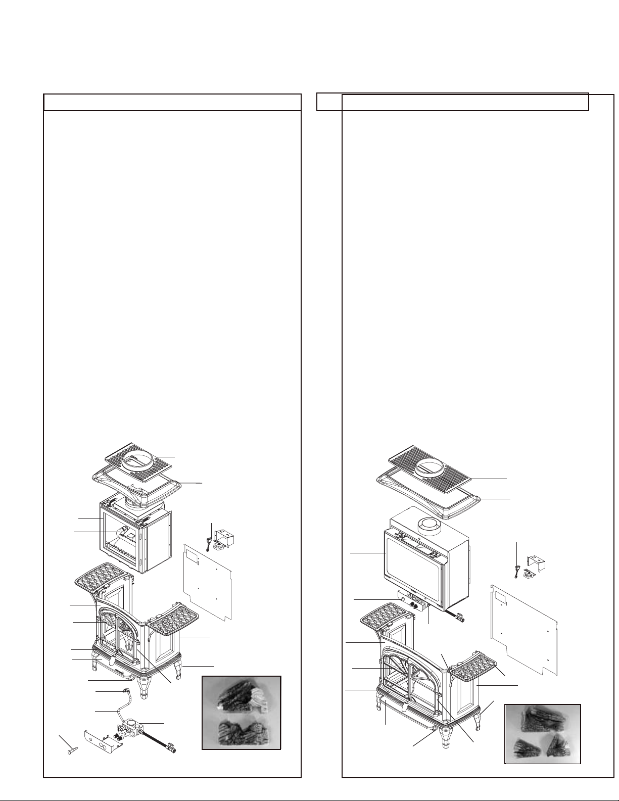
TIARA I & II (NG, LP) Service Parts List / (GN, PL) Liste des pièces de rechange with
Exploded Parts Diagram / (GN, PL) Vue éclatée des pièces
IMPORTANT: THIS IS DATED INFORMATION. The most current information is located on your dealers VIP site. When ordering, supply serial and
model numbers to ensure correct service parts. / IMPORTANT : L'information fournie dans cette brochure n'est valide que pendant une courte période.
Les sites VIP des distributeurs disposent des renseignements les plus récents. Lors d'une commande, veuillez fournir les numéros de série et de
modèles pour un remplacement adéquat des pièces.
Item/Piece Common Parts/ Pi`eces Serial# Part Number/
Communes N’ De S`erie N’De Pi`ece
1. Grill/Grill 281-746
2. Top/Somment 281-747
3. Side/Cote 281-750
4. Leg/Pied 282-741
5. Front/Front 281-749
6. Left Door/Porte Gauche 281-754
7. Right Door/Porte Juste 281-755
8. Ashlip/Ashlip 281-752
9. Skirt/Jupe 281-753
10.Base/Base 281-751
11.Shelf/Planche 282-734
12.Shelf Support/Appui de planche 282-735
13.ON/OFF Rocker Switch/Interrupteur
a bascule marche/arret 060-525A
14.Burner/Bruleur 585-325A
15.Burner Tube/ Tube de bruleur 844-5000
15.Orice LP/Orice PL Pre 20000 060-801
Post 20000 844-1940
16.Orice NG/ Orice GN Pre 20000 057-800
Post 20000 844-7220
17.Valve Assembly NG/ Module de
Valve GN 842-0240
17.Valve Assembly LP/ Module de alve PL 842-0230
18.Piezo Ignitor/Allumage Piezo 842-0361
19.Glass Door Assembly/Module de Porte
en verre 844-9300
20.Log Set Assembly/Jeu de buches 844-9320
Pilot Orice NG/Orice de
vielleuse GN Pre 20000 571-516
Post 20000 842-4260
Pilot Orice LP/Orice de
veilleuse PL Pre 20000 571-517
Post 20000 842-4270
Pilot Assembly NG/Module de veilleuse GN 842-4280
Thermocouple/Thermocouple 842-4250
Thermopile/Thermopile 842-0250
1
Item/Piece Common Parts/ Pi`eces Serial# Part Number/
Communes N’ De S`erie N’De Pi`ece
1. Grill/Grill 282-732
2. Top/Somment 282-733
3. Side/Cote 282-737
4. Leg/Pied 282-741
5. Front/Front 282-736
6. Left Door/Porte Gauche 282-742
7. Right Door/Porte Juste 282-743
8. Ashlip/Ashlip 282-739
9. Skirt/Jupe 282-740
10.Base/Base 282-738
11.Shelf/Planche 282-734
12.Shelf Support/Appui de planche 282-735
13.ON/OFF Rocker Switch/Interrupteur
a bascule marche/arret 060-525A
14.Valve Assembly NG/ Module de
Valve GN 842-0240
14.Valve Assembly LP/ Module de alve PL 842-0230
15.Piezo Ignitor/Allumage Piezo 842-0361
16.Glass Door Assembly/Module de Porte
en verre Pre 30000 586-600A
Post 30000 844-6080
17.Log Set Assembly/Jeu de buches 844-9330
Burner/Bruleur 844-9290
Burner Tube/Tube de bruleur 844-5000
Orice LP/Orice PL Pre 30000 065-801
Post 30000 844-5850
Orice NG/Orice GN Pre 30000 586-800
Post 30000 844-8310
Pilot Orice NG/Orice de
vielleuse GN Pre 30000 571-516
Post 30000 842-4260
Pilot Orice LP/Orice de
veilleuse PL Pre 30000 571-517
Post 30000 842-4270
Pilot Assembly NG/Module de veilleuse GN 842-4280
Thermocouple/Thermocouple 842-4250
Thermopile/Thermopile 842-0250
2
19
14
5
6
10
8
9
16
15
18
7
17
20
13
16
15
3
4
5
6
10
8
14
12
9
7
1
2
13
11
3
4
17
TIARA I EXPLODED DRAWING
/Vue éclatée des pièces
TIARA II EXPLODED DRAWING
5
/Vue éclatée des pièces
Page 6
1
Approvals and Codes
Homologations et codes d’installation
Approvals Listing and Codes
Appliance Certication
The Heat N Glo gas stove models discussed in this
Installers Guide have been tested to certification
standards and listed by the applicable laboratories.
CERTIFICATION STANDARD
MODEL Tiara I and II
LABORATORY Underwriters Laboratories
TYPE Direct Vent Gas Fireplace Heater
STANDARD ANSIZ21.88•CSA2.33•UL307B
Installation Codes
Installation must conform to local codes. In the
absence of local codes installation must conform
to the National Fuel Gas Code ANSI Z223.1 (in the
United States) or with the current installation code
CAN/CGA-B149 (in Canada).
The appliance must be electrically grounded in
accordance with local codes or, in the absence of local
codes with the National Electric Code ANSI/NFPA
No. 70 (in the United States), or with the current CSA
C22.1 Canadian Electric Code (in Canada).
Homologations et codes
Certications
Les modèles d’appareils de chauffage Heat N Glo
présentés dans ce Guide d’installation ont été soumis
à des tests d’homologation standard et ont été
approuvés par les laboratoires concernés.
CERTIFICATION STANDARD
MODÈLE Tiara I et II
LABORATOIRE Underwriters Laboratories
TYPE Cassette de cheminée à gaz à
système d’évacuation directe
STANDARD ANSIZ21.88•CSA2.33•UL307B
Codes d’installation
L’installation doit être conforme aux codes locaux. En
l’absence de codes locaux, se conformer au National
Fuel Gas Code ANSI Z223.1 (aux États-Unis) ou
aux code courant d’installation CAN/CGA - B149
(au Canada).
L’appareil doit être mis à la masse conformément
aux codes locaux ou, en l’absence de ces derniers,
conformément au National Electric Code ANSI/NFPA
No. 70 (aux États-Unis) ou au Code Électrique
Canadien CSA C22.1 (au Canada).
High Altitude Installations
These units are tested and approved for elevations
from 0 to 2,000 feet (in the United States) and from
2,000 to 4,500 feet (in Canada).
When installing this unit at an elevation above 2,000
feet (in the United States), it may be necessary to
decrease the input rating by changing the existing
burner orifice to a smaller size. Input should be
reduced four percent (4%) for each 1,000 feet above
sea level. Check with your local gas company for help
in determining the proper orice size.
When installing this unit at an elevation above 4,500
feet (in Canada), check with local authorities.
Consult your local gas utility for assistance in
determining the proper orice for your location.
Installations à haute altitude
Ces modèles ont été testés et approuvés pour des
altitudes comprises entre 0 et 600 m (0 et 2000
ft) (aux États-Unis) et 0 et 1 350 m (0 et 4500 ft)
(au Canada).
Pour installer cet appareil à une altitude supérieure
à 600 m (2000 ft) (aux États-Unis), il peut s’avérer
nécessaire de réduire l’admission en réduisant
l’ouver ture du diaphragme du brûleur. Réduire
l’admission de 4% tous les 300 m (1000 ft) supplémentaires au-dessus du niveau de la mer. Pour
déterminer l’ouverture correcte du diaphragme,
consulter le fournisseur de gaz local.
Pour installer cet appareil au-dessus de 1 350 m
(4500 ft) (au Canada), consulter les autorités locales.
Consulter le fournisseur de gaz local pour déterminer
l’ouverture correcte du diaphragme pour la région.
6
Page 7

2
Getting Started
Mise en marche
Introducing the Heat N Glo
Direct Vent Gas Stoves
Heat-N-GLo direct vent gas stoves are designed to
operate with all combustion air siphoned from outside
of the building and all exhaust gases expelled to the
outside. The information contained in this Installers
Guide, unless noted otherwise, applies to all models
and gas control systems. Gas stove diagrams, including the dimensions, are shown in this section.
Pre-installation Preparation
This gas stove and its components are tested and
safe when installed in accordance with this Installers
Guide. Report to your dealer any parts damaged
in shipment, particularly the condition of the glass.
Do not install any unit with damaged, incomplete,
or substitute parts.
The vent system components and trim doors are
shipped in separate packages. The gas logs are
packaged separately and must be field installed.
Read all of the instructions before starting the
installation. Follow these instructions carefully
during the installation to ensure maximum safety
and benet. Failure to follow these instructions
will void the owner’s warranty and may present
a re hazard.
The Heat-N-Glo Warranty will be voided by, and
Heat-N-Glo disclaims any responsibility for, the
following actions:
• Installation of any damaged stove or vent system
component.
• Modication of the stove or vent system.
• Installation other than as instructed by Heat-NGlo.
• Improper positioning of the gas logs or the glass
door.
• Installation and/or use of any component part not
manufactured and approved by Heat-N-Glo, not
withstanding any independent testing laboratory
or other party approval of such component part
or accessory.
Présentation des appareils de chauffage
Heat N Glo à ventilation directe
Les appareils de chauffage Heat-N-Glo à ventilation
directe sont prévus pour aspirer l’air de l’extérieur et
refouler les gaz d’échappement à l’extérieur.
Sauf avis contraire, les informations gurant dans ce
Guide d’installation s’appliquent à tous les modèles et à
tous les systèmes de commande.
Les schémas d’installation, y compris les dimensions,
gurent dans cette section.
Avant l’installation
L’appareil à gaz et ses éléments ont été testés et
présentent toutes les garanties de sécurité si l’installation
est effectuée conformément aux instructions de ce Guide
d’installation. Signaler au concessionnaire les pièces
endommagées pendant le transport et en particulier la
vitre. Ne pas installer l’appareil de chauffage avec
des pièces endommagées, incomplètes ou avec des
pièces de substitution.
Les éléments du système de ventilation et les encadrements de porte sont livrés dans des emballages séparés.
Les bûches au gaz sont emballées séparément et
doivent être installées sur place. Lire toutes les
instructions avant d’entreprendre l’installation.
Suivre soigneuse-ment ces instructions tout au
long de l’installation pour assurer le maximum de
sécurité et le meilleur rendement. Le non-respect
de ces instructions annule la garantie et crée un
risque d’incendie.
La garantie de Heat-N-Glo est annulée, et Heat-N-Glo se
dégage de toute responsabilité dans les cas suivants:
• Installation d’un appareil de chauffage ou d’un
système de ventilation endommagé.
• Modication de l’appareil de chauffage ou du système
de ventilation.
• Installation différente de celle recommandée par
Heat-N-Glo.
• Positionnement incorrect des bûches ou de la porte
en verre.
• Montage et/ou utilisation de pièces non fabriquées et
par Heat-N-Glo même si elles ont été homologuées
par un laboratoire indépendant ou une autre agence
compétente.
CES SITUATIONS PEUVENT CRÉER DES RISQUES
D’INCENDIE.
ANY SUCH ACTION MAY POSSIBLY CAUSE A
FIRE HAZARD.
7
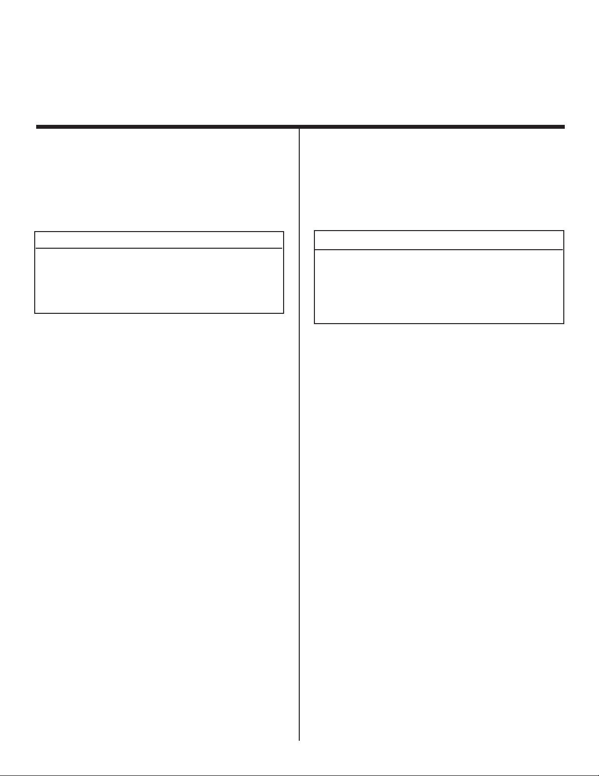
Page 8
Getting Started (continued)
27 1/8
(688mm)
26 1/8
(664mm)
6 7/8
(175mm)
10 1/2 (267mm)
15 1/4
(387mm)
Ø6 5/8 (168mm)
21 (533mm)
18 3/4
(478mm)
7 (179mm)
35
(889mm)
13
(330mm)
Mise en marche (suite)
When planning a stove installation, it’s necessary
to determine:
• Where the unit is to be installed.
• The vent system conguration to be used.
• Gas supply piping.
• Electrical wiring.
• Framing and nishing details.
• Whether optional accessories—devices such as a
fan, wall switch, or remote control—are desired.
If the stove is to be installed on carpeting or tile,
or on any combustible material other than wood
ooring, the stove should be installed on a metal
or wood panel that extends the full width and depth
of the stove.
Figure 1. Diagram of the Tiara I
Avant d’entreprendre l’installation d’un appareil de
chauffage, déterminer:
• L’emplacement de l’appareil.
• La conguration du système de ventilation.
• La tuyauterie pour l’alimentation en gaz.
• Le câblage électrique.
• L’encadrement et les nitions.
• L’utilisation ou non d’accessoires (en option) tels
que ventilateur, interrupteur mural ou commande
à distance.
En cas d’installation sur de la moquette, du linoléum
ou sur tout revêtement combustible autre que du
parquet de bois, poser l’appareil sur une plaque
métallique ou un panneau de bois aux dimensions
de l’appareil.
Figure 1. Schéma du modèle Tiara I
8
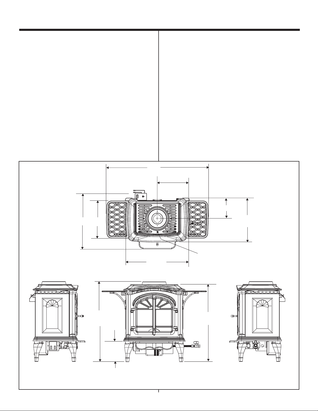
Page 9
Getting Started (continued)
29 1/2 (749mm)
7 1/2
(191mm)
14 3/4 (375mm)
Ø6 5/8 (168mm)
15 1/4 (387mm)
19 3/8
(491mm)
30 1/8
(766mm)
6 7/8
(174mm)
29 1/4
(742mm)
13
(330mm)
43 1/2
(1105mm)
Mise en marche (suite)
Figure 2. Diagram of the Tiara II
Figure 2. Schéma du modèle Tiara II
9
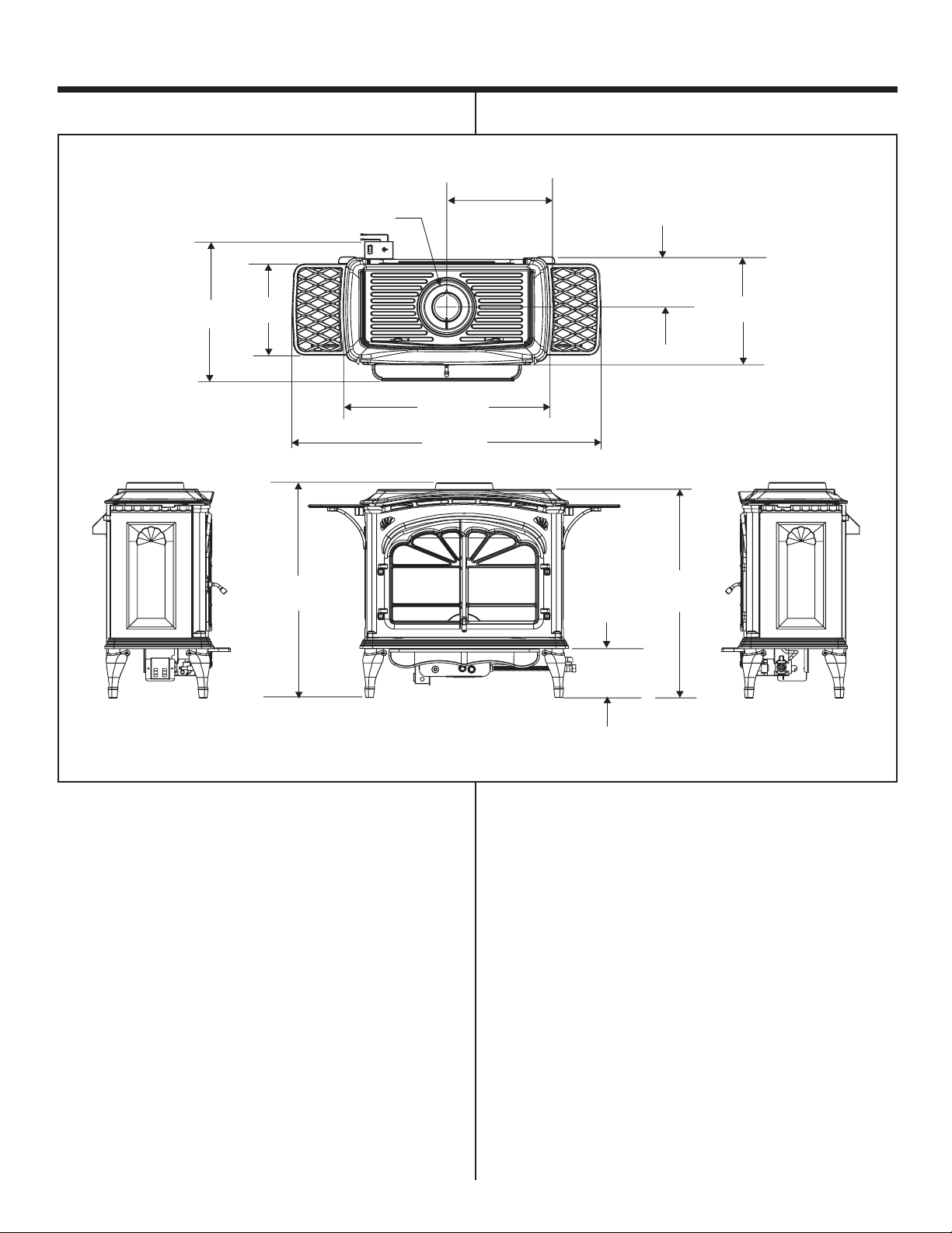
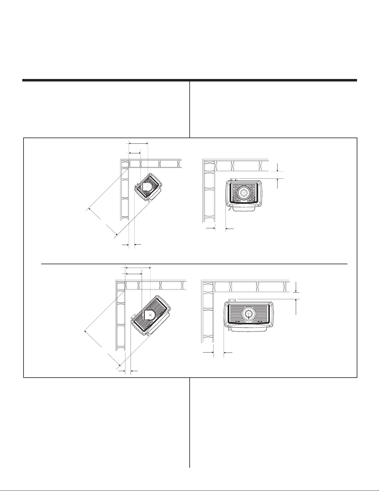
Page 10
3
16 1/8 (410mm)
9 7/8 (251mm)
33 3/8 (848mm)
4 5/8 (118mm)
4 (101mm)
6 (152mm)
4 (102mm)
36 3/4 (933mm)
18 1/2 (470mm)
12 1/4 (31 1mm)
6 (152mm)
9 (229mm)
Installing the Stove
Installation
Step 1
Locating the Stove
The diagram below shows space and clearance
requirements for locating the stove within a room.
Tiara I
Étape 1
Emplacement
Le schéma ci-dessous indique les dégagements et
les espaces d’isolation à prévoir pour l’installation de
l’appareil de chauffage dans une pièce.
Tiara II
Figure 3. Stove Dimensions, Locations, and
Space Requirements
Clearance Requirements
The minimum clearance to a perpendicular wall
extending past the face of the stove is six inches
(150mm).
The back of the stove may NOT be recessed into
combustible construction.
Figure 3. Dimensions, emplacement et
dégagements à prévoir
Distances d’isolation à prévoir
La distance minimum entre l’appareil de chauffage
et un mur perpendiculaire dépassant l’avant de
l’appareil est de 150 mm (6 in.).
L’arrière de l’appareil de chauffage NE PEUT PAS
être encastré dans une construction combustible.
10
Page 11
Installing the Stove (continued) Installation (suite)
Minimum Clearances
from the Stove to Combustible Materials
Distance minimum entre de ventilation de chauffage
et les matériaux combustibles
Inches m m
Glass Front 36 914 Vitre Avant
Floor 0 0 Plancher
Rear (Tiara I) 4 102 Arrière (Tiara I)
(Tiara II) 6 152 (Tiara II)
Sides (Tiara I) 6 152 Côtés de l’appareil (Tiara I)
(Tiara II) 9 229 (Tiara II)
Floor to Ceiling 72 1830 Plancher au plafond
Minimum Clearances from the
Vent Pipe to Combustible Materials
For Horizontal Sections: Top 3 inches
Bottom 1 inch
Distances minimum entre le conduit
de ventilation et les matériaux combustibles
Sections horizontales: Haut 75mm
Bas 25mm
Sides 1 inch
For Vertical Sections: 1 inch
At Wall Firestops: Top 2 1/2 inches
Bottom 1/2 inch
Sides 1 inch
For minimum clearances, see the direct vent
termination clearance diagrams on page 27 thru 29
in this manual.
Côtés 25mm
Sections verticales: 25mm
Coupe-feu mural: Haut 63,7mm
Bas 13mm
Côtés 25mm
Pour les distances d’isolation minimum, voir les
schémas de mitres de ventilation directe, page 27
et 29 de ce guide.
11
Page 12
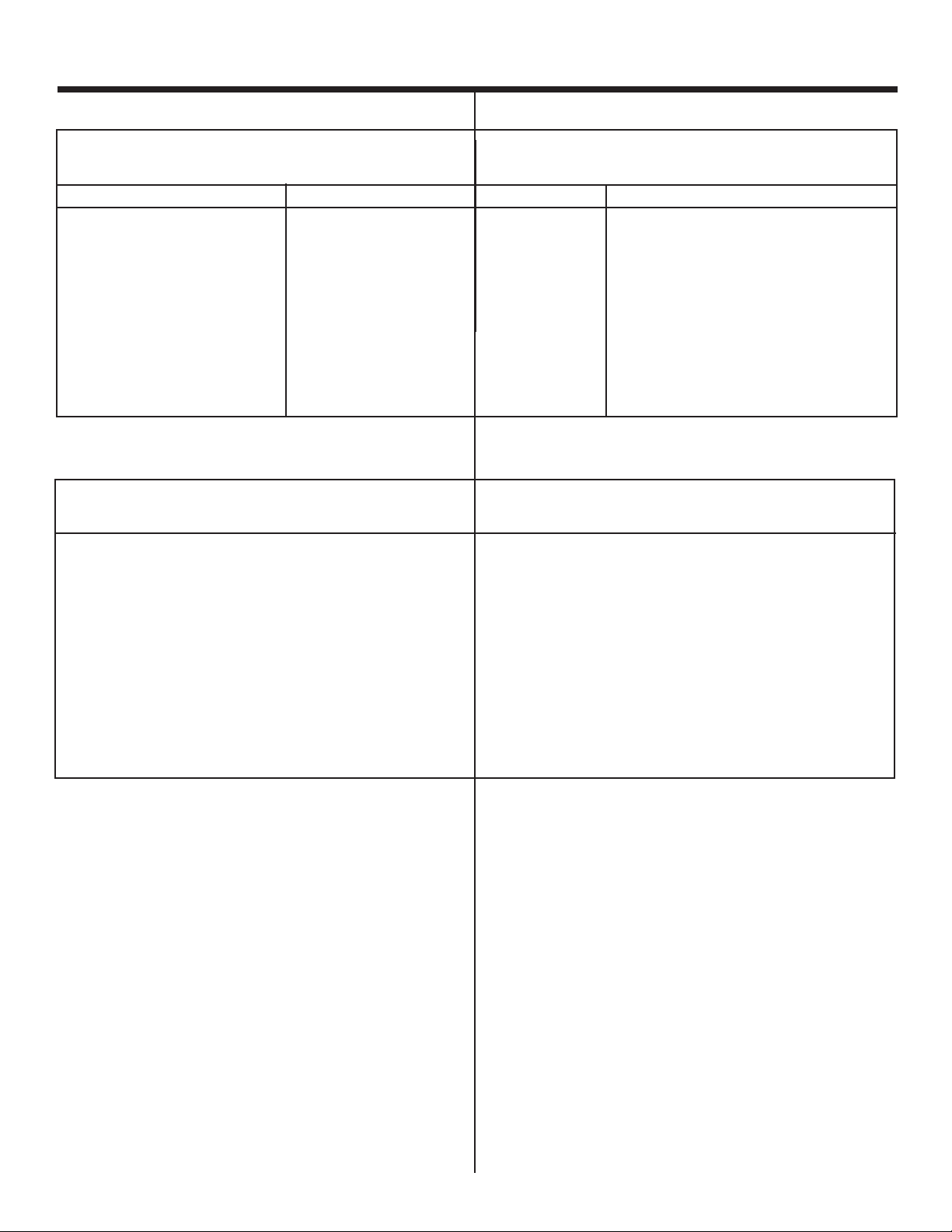
Installing the Stove (continued)
SLK-01D
SLK-991D Aor(ou)
SLK-980D
LINK-ST OVE
SLK-01TRD
HORIZONT AL
TERMINA TION
(MITRE
HORIZONT ALE)
WALL FIREST OP
(COUPE-FEU MURAL)
90 DEGREE
ELBOW
(COUDE A90)
O
VERTICAL
TERMINA TION
(MITRE VERTICALE)
ST ORM COLLAR
(COLLIER D’ORAGE)
ROOF FLASHING
(SOLIN)
HORIZONT AL PIPE
SUPPORT
(SUPPORT DE
CONDUIT HORIZONT AL)
PIPE LENGTH
(SECTION DE CONDUIT)
WALL BRACKET
(SUPPORT MURAL)
CEILING
FIREST OP
(COUPE-FEU DU
PLAFOND)
COMPONENT
IDENTIFICA TION
(IDENTIFICA TION
DES ELEMENTS)
Installation (suite)
Step 2
Installing the Vent System
A. Vent System Approvals
This model is approved for 4”/6 and 5/8” SL D-Series
vent pipe components and terminations. This pipe is
tested and listed as an approved component of the
stove. The pipe is tested to run inside an enclosed
wall. There is no requirement for inspection openings
at each joint within the wall. There is no required
pitch for horizontal vent runs. Approved vent systems
components are labeled for identication. NO OTHER
VENT SYSTEMS OR COMPONENTS MAY BE USED.
Detailed installation instructions are included with each
vent termination kit and should be used in conjunction
with this manual.
WARNING: A minimum 2 foot length of straight
!
vent pipe MUST be attached to the unit’s starting
collars for all vent systems unless using the
Optional Kit #970D on model Tiara I.
Identifying Vent Components
The vent systems installed on this gas stove may
include one, two, or three 90° elbow assemblies. The
relationships of vertical rise to horizontal run in vent
configurations using 90° elbows MUST BE strictly
adhered to. The rise to run relationships are shown in
the vent drawings and tables. Refer to the diagrams
on the next several pages.
Étape 2
Installation du système de ventilation
A. Homologations du système de ventilation
Ce modèle est homologué pour les éléments et mitres
d’un système de ventilation de 4 in. et 6 5/8 in. de la
série SL D. Ce conduit a été testé et homologué en
tant qu’élément agréé de la cheminée. Le conduit a été
testé en vue d’etre posé a l’intérieur d’un mur fermé.
Aucune spécication n’exige la présence d’ouvertures
d’inspection au niveau de chaque joint a l’intérieur du
mur. Il n’existe aucune spécication de pente pour les
conduits horizontaux. Des autocollants sont apposés
sur les éléments homologués. N’UTILISER AUCUN
AUTRE SYSTÈME OU ÉLÉMENT DE VENTILATION.
Les instructions de montage détaillées qui
accompagnent chaque kit de mitre doivent être lues et
assimilées avec ce Guide d’installation.
AVERTISSEMENT : Avec tous les systèmes
!
d’évacuation, un conduit droit d’au moins 61 cm
de long DOIT être rattaché aux collets de raccord
de l’appareil, sauf si le module facultatif n°970D
est utilisé sur le modèle Tiara I.
Éléments du système de ventilation
Les systèmes de ventilation utilisés avec cet appareil
de chauffage au gaz peuvent inclure un, deux ou trois
coudes à 90°. Les rapports entre les sections verticales
et les sections horizontales dans les configurations
utilisant des coudes à 90° DOIVENT être respectés. Les
schémas et tableaux relatifs au système de ventilation
indiquent les rapports entre les sections verticales et
les sections horizontales. Voir les schémas des pages
suivantes.
u
Figure 4. Vent Components and Terminations
Vent System Termination Kits
(Kits de mitres)
Figure 4. Éléments du système de ventilation et mitres
12
u
Page 13
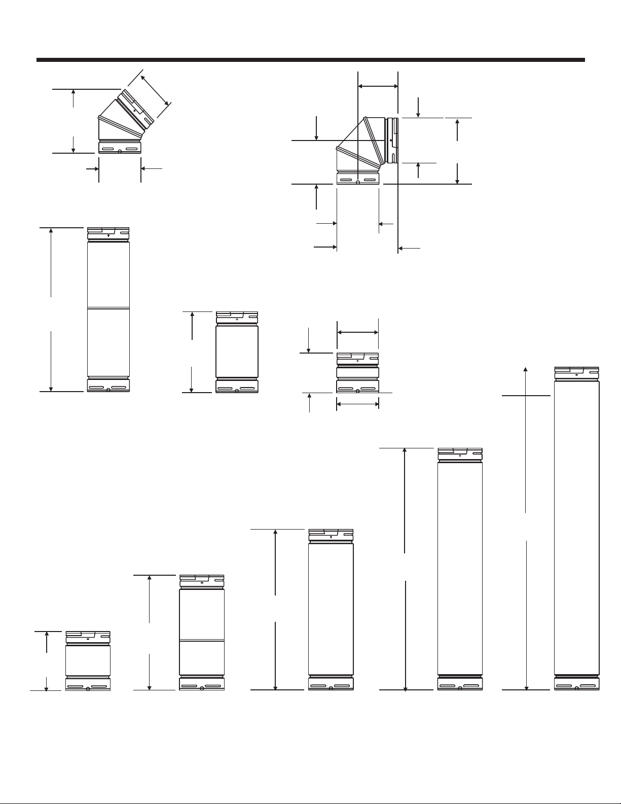
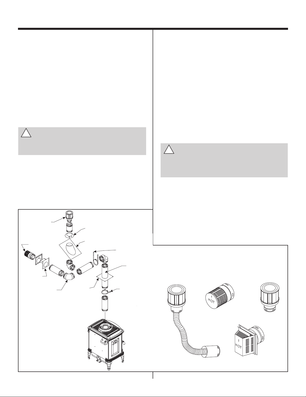
Installing the Stove (continued)
9 1/4 in.
(235mm)
6 5/8 in.
(168mm)
6 1/2 in.
(165mm)
6 3/8 in.
(162mm)
6 1/2 in.
(165mm)
9 5/8 in.
(244mm)
9 5/8 in.
(244mm)
6 5/8 in.
(168mm)
6 3/8 in.
(162mm)
SL-45D
SL-90D
SL-17/24D
(SL17-24D
)
17-2 4in.
(432-610mm)
SL-06D
SL-12 D
53/4 in .
(146mm)
6 5/8 in .
(244mm)
6 1/2 in .
(165mm)
11 3/4 in .
(298mm)
83/4 in .
(222mm)
SL-09D
12-17 in .
(305-432mm)
SL-12/17 D(SL12-17D ) SL-24D
SL-36D
SL-48D
47 3/4in.
(121,28cm )
35 3/4in.
(908mm)
23 3/4 in .
(603mm)
Installation (suite)
Figure 5. SL D-Series Direct Vent
Component Specications
(4-inch inner pipe 6-5/8-inch
outer pipe)
13
Figure 5. Caractéristiques des éléments de
ventilation directe de la série SL-D
(conduit intérieur de 4 in. et conduit
extérieur de 6-5/8 in.)
Page 14

Installing the Stove (continued)
Installation (suite)
Straight Vertical Vent System
Tiara I
When a vertical run of 12 feet and higher is attached
directly to the top of the stoves, further baffling
is necessary to maintain high efciency. A round
baffle with a tab on each side is included in the
manual bag assembly. To install the round baffle
follow these steps:
1. Open the doors.
2. Remove logs and set aside.
3. Disassemble the square bafe by unfastening
four screws located inside top of the rebox. See
Figure 6 on Page 15.
4. Unfasten the two screws on the existing round
bafe, and replace it with the new round bafe.
Note: The new round bafe is bigger than the
existing round bafe already on the unit.
5. Re-install the square bafe removed in Step 3.
Système de ventilation vertical droit
Tiara I
Lorsqu’une section verticale égale ou supérieure à
3,65 m (12 ft) est attachée directement en haut de
l’appareil de chauffage, un déecteur supplémentaire
est nécessaire pour obtenir un rendement maximum.
Un déecteur rond muni de une languette d’attache
de chaque côté est compris dans le sac de montage
du guide. Pour installer le déecteur rond, suivre les
instructions suivantes:
1. Ouvrez les portes.
2. Retirer les bûches et les mettre de côté.
3. Démonter le déecteur carré en desserrant les
quatre vis placées à l’intérieur, sur le dessus de
foyer. Voir la gure 6 Page 15.
4. Desserrer les deux vis sur le déflecteur rond
déjà en place et installer le déecteur rond neuf.
Remarque: Le déecteur rond neuf est plus grand
que le déecteur déjà installé sur l’appareil de
chauffage.
Tiara II
The Tiara II has an adjustable flue restrictor for
maximum performance for vertical installations.
The unit is shipped with the restrictor in the open
position and should be left open with any horizontal
installations. The adjustment screw can be accessed
by opening the front face. The slot of the screw
head indicates the position of the restrictor. Turn the
screw with a straight blade screwdriver to close the
restrictor as necessary. A qualied technician must
make the adjustment.
The amount to close the restrictor will depend on
the vent height. The setting will vary depending on
the installation.
Any offsets in a vertical installation will restrict the
system and the ue restrictor will not need to be
closed as much.
5. Remettre en place le déecteur carré déposé
à l’étape 3.
Tiara II
Le foyer Tiara II est équipé d’un réducteur de débit
d’évacuation réglable pour obtenir des performances
optimales sur les installations verticales. L’appareil
est livré avec le limiteur de débit en position ouverte.
Celui-ci doit rester ouvert sur les installations
horizontales. La vis de réglage est accessible en
ouvrant la façade. La fente de la tête de vis indique
la position du limiteur de débit. Tournez la vis à l’aide
d’un tournevis à lame plate pour fermer le limiteur
de débit, si nécessaire. Un technicien qualié doit
faire l’ajustement.
Le degré de fermeture du limiteur de débit dépend
de la hauteur du conduit d’évacuation. La position
varie selon l’installation.
Tout dévoiement de conduit dans une installation
verticale limite le débit du système d’évacuation et il
n’est alors pas nécessaire de fermer autant le limiteur
de débit de fumée.
14
Page 15

Installing the Stove (continued)
FIREBOX TOP
(FOYER SUPERIEURE)
ROUND BAFFLE
(D FLECTEUR ROND )È
SQUARE BAFFLE
(D FLECTEUR CARRÉ)È
Installation (suite)
Air Shutter Adjustment (Tiara II only)
The air shutter adjusts the amount of air that mixes
with the gas as it enters the burner pan. It is used to
ne tune the ame as necessary for differences in
altitude and vent conguration. The shutter is shipped
in the open position.
It can be adjusted by opening the front face and
turning the adjustment screw.
Turning the screw in will close the shutter; turning the
screw out will open the shutter.
The shutter can be adjusted while the unit is in
operation.
Allow the unit to operate about 15-20 minutes. This
will give the ame time to reach its height and color
before making adjustments to the air shutter. As
the shutter is closed, the flame should get taller
and darker.
Réglage de l’obturateur d’air (Tiara II seulement)
L’obturateur d’air règle la quantité d’air qui se mélange
au gaz qui entre dans la cuvette du brûleur. Il sert
à ajuster la amme avec précision an d’adapter le
système aux différentes altitudes et congurations
du conduit d’évacuation. L’obturateur est livré en
position ouverte.
Il peut être réglé en ouvrant la façade et en tournant
la vis de réglage.
Si vous tournez la vis de réglage de façon à ce qu’elle
s’enfonce, l’obturateur se ferme ; si vous la tournez de
façon à ce qu’elle sorte, l’obturateur s’ouvre.
L’obturateur peut être réglé pendant que l’appareil
est en marche.
Laissez l’appareil fonctionner pendant 15-20 minutes.
La amme aura ainsi le temps d’atteindre sa taille et sa
couleur habituelles avant que vous régliez l’obturateur
d’air. Au fur et à mesure que l’obturateur se ferme, la
amme devient plus haute et plus foncée.
Tiara I
Figure 6
15
Page 16

Installing the Stove (continued)
V
VERTICAL VENT
(VENTILATION VERTICALE)
2’ (610mm) MIN.
40’ (1200cm) MAX.
Installation (suite)
V
Figure 7. Straight Vertical Vent
System
Figure 7. Système de ventilation
vertical droit
16
Page 17

Installing the Stove (continued)
H
V
Installation (suite)
VENTING WITH ONE (1) 900 ELBOW
Tiara I
(VENTILATION AVEC UN (1) COUDE À 900)
V H
2’MIN.(610mm) 2’MAX.(610mm)
3’MIN.(914mm) 3’MAX.(914mm)
4’MIN.(120cm) 4’MAX.(120cm)
18’ MIN.(540cm) 18’ MAX.(540cm)
V + H = 40’ MAX.(1200cm)
H = 18’ MAX.(540cm)
VENTING WITH ONE (1) 900 ELBOW
Tiara II
(VENTILATION AVEC UN (1) COUDE À 900)
V H
2’MIN.(610mm) 2’MAX.(610mm)
3’MIN.(914mm) 3’MAX.(914mm)
4’MIN.(120cm) 4’MAX.(120cm)
18’ MIN.(540cm) 15’ MAX.(450cm)
V + H = 40’ MAX.(1200cm)
H = 15’ MAX.(450cm)
NOTE: Optional Kit #970D can be
used for this type of installation on
model Tiara I.
REMARQUE: Le kit no 970D en option
peut être utilisé pour ce type
d’installation du modèle Tiara I.
Figure 8. Vent System with One
90° Elbow
Figure 8. Système de ventilation
avec un coude à 90°
17
Page 18

Installing the Stove (continued)
V
H
V
1
H
1
Installation (suite)
VENTING WITH TWO (2) 90o ELBOWS
Tiara I
(VENTILATION AVEC DEUX (2) COUDES À 90
V H
2’ MIN.(610mm) 2’ MAX.(610mm)
3’ MIN.(914mm) 3’ MAX.(914mm)
4’ MIN.(120cm) 4’ MAX.(120cm)
18’ MIN.(540cm) 18’ MAX.(540cm)
V + V1 + H = 40’ MAX.(1200cm)
H = 18’ MAX.(540cm)
VENTING WITH TWO (2) 90o ELBOWS
Tiara II
(VENTILATION AVEC DEUX (2) COUDES À 90°
V H
2’ MIN.(610mm) 2’ MAX.(610mm)
3’ MIN.(914mm) 3’ MAX.(914mm)
4’ MIN.(120cm) 4’ MAX.(120cm)
18’ MIN.(540cm) 15’ MAX.(450cm)
V + V1 + H = 40’ MAX.(1200cm)
H = 15’ MAX.(450cm)
Figure 9. Vent System with Two
90° Elbows
Figure 9. Ventilation avec deux
coudes à 90°
18
Page 19

Installing the Stove (continued)
V
H
V
1
H
1
H
V
H
1
V
1
Installation (suite)
VENTING WITH THREE (3) 90o ELBOWS
(VENTILATION AVEC TROIS (3) COUDES À 90°)
V H
2’ MIN.(610mm) 2’ MAX.(610mm)
3’ MIN.(914mm) 3’ MAX.(914mm)
4’ MIN.(120cm) 4’ MAX.(120cm)
18’ MIN.(540cm) 18’ MAX.(540cm)
V+V1+H+H1 = 40’ MAX.(1200cm)
H+H1 = 18’ MAX.(540cm)
Tiara I
Figure 10. Vent System with three 90° elbow
Tiara II
VENTING WITH THREE (3) 90o ELBOWS
(
VENTILATION AVEC TROIS (3) COUDES À 90
V H
2’ MIN.(610mm) 2’ MAX.(610mm)
3’ MIN.(914mm) 3’ MAX.(914mm)
4’ MIN.(120cm) 4’ MAX.(120cm)
18’ MIN.(540cm) 15’ MAX.(450cm
V+V1+H+H1 = 40’ MAX.(1200cm)
H+H1 = 15’ MAX.(450cm)
Figure 10. Ventilation avec trois coudes à 90°
19
Page 20

Installing the Stove (continued)
Installation (suite)
B. Installing Vent Components
Before starting installation of vent kits, the installer
should read Installing the Vent System on pages 12
thru 22, to ensure that the proper system has been
selected for the installation.
Determine the exact position of the stove so the
vent pipe is centered (if possible) between two
building framing members. This will avoid any extra
framing. Using a level, make sure the stove is properly
positioned and squared. Minimum clearances to walls
and ceilings must be maintained.
Vent terminals should not be recessed into a wall.
Consult your local Building Code Regulations before
beginning the installation.
!
WARNING: THIS GAS STOVE AND VENT
ASSEMBLY MUST BE VENTED DIRECTLY
TO THE OUTSIDE AND MUST NEVER BE
ATTACHED TO A CHIMNEY SERVING A
SEPARATE SOLID FUEL BURNING APPLIANCE. EACH GAS APPLIANCE MUST USE
A SEPARATE VENT SYSTEM. COMMON
VENT SYSTEMS ARE PROHIBITED.
1. Attach the First Vent Component to the
Starting Collars
To attach the rst vent component to the starting
collars of the stove:
• Apply a 3/8 inch (9.5mm) bead of stove cement
around the 4 inch (100mm) fireplace starting
collar.
• Lock the vent components into place by sliding
the concentric pipe sections with four (4) equally
spaced interior beads into the replace collar or
previously installed component end with four (4)
equally spaced indented sections.
• When the internal beads of each outer pipe line
up, rotate the pipe section clockwise about onequarter (1/4) turn. The vent pipe is now locked
together.
B. Pose des éléments de ventilation
Avant de commencer l’installation, lire les instructions
du Guide d’installation de l’appareil de chauffage
et les instructions des kits de ventilation pages 12
thru 22, pour s’assurer que le système de ventilation
sélectionné est correct.
Essayer de déterminer l’emplacement exact de
l’appareil de chauffage de façon à ce que le conduit
de ventilation soit centré entre deux montants
de charpente, pour éviter d’avoir à construire un
encadrement supplémentaire. À l’aide d’un niveau,
s’assurer que l’appareil de chauffage est placé
correctement et en équerre. Respecter les distances
d’isolation minimum entre l’appareil et les murs ou
les plafonds.
Les mitres ne doivent pas être encastrées dans un
mur. Consulter les codes de construction locaux avant
de commencer l’installation.
!
AVERTISSEMENT: CET APPAREIL DE
CHAUFFAGE AU GAZ ET SON SYSTÈME
DE VENTILATION DOIVENT COMMUNIQUER DIRECTEMENT AVEC L’AIR
EXTÉRIEUR ET NE DOIVENT JAMAIS
ÊTRE RACCORDÉS À UNE CHEMINÉE
DESSERVANT UN APPAREIL SÉPARÉ
BRÛLANT DES COMBUSTIBLES
SOLIDES. CHAQUE APPAREIL AU GAZ
DOIT DISPOSER D’UN SYSTÈME DE
VENTILATION SÉPARÉ. LES SYSTÈMES
DE VENTILATION EN COMMUN SONT
1. Pose de la première section du conduit de
ventilation sur les colliers de départ
Pour poser la première section sur les colliers de
départ de l’appareil de chauffage:
• Mettre un let de ciment réfractaire de 9,5 mm
(3/8 in.) autour du collier de départ de 100 mm
(4 in.).
• Verrouiller les sections du conduit de ventilation en
glissant dans le collier de l’appareil de chauffage
soit les sections concentriques avec quatre (4)
lets intérieurs uniformément espacés, soit les
éléments préalablement posés avec quatre (4)
sections à encoches uniformément espacées.
• Une fois que les filets intérieurs des conduits
extérieurs sont alignés, tourner les sections de
conduit d’un quart (1/4) de tour dans le sens
horaire. Les sections du conduit sont ainsi verrouillées.
20
Page 21

Installing the Stove (continued)
ST ARTING COLLA R
(COLLIE RDE DÉP ART )
FIRST VENT
COMPONENT
(PREMIÈRE SECTIO N
DU CONDUI T
DE VENTILA TION)
ST OVE SEALANT BEAD 3/8"
(FILE TDECIMENT
RÉFRACT AIRE 9,5 mm)
1INCH (25.4 mm)
1. Apply the stove cement.
2.Line up the internal beads
and rotate the pipe sections
clockwise until locked.
3. Lock the vent components
into place.
Installation (suite)
1. Mettre du ciment réfractaire.
2. Aligner les lets
intérieurs et tourner
les sections de conduit
dans le sens horaire
jusqu’à ce qu’elles se
bloquent.
3. Verrouiller les sections
en place.
Figure 11.
Attaching the First
Vent Component to the
Starting Collars
WARNING: A 3/8 INCH (9.5 mm) BEAD
!
OF STOVE CEMENT MUST BE PLACED
AROUND THE STOVE STARTING COLLAR
BEFORE ATTACHING THE FIRST VENT
COMPONENT. FAILURE TO SEAL THIS
JOINT MAY CAUSE THE STOVE TO OPERATE
IMPROPERLY. SEE THE DIAGRAM.
2. Continue Adding Vent Components
To continue adding vent components in accordance
with the pre-planned vent system conguration:
• Ensure that each succeeding vent component
is securely tted and locked into the preceding
component in the vent system.
90° elbows may be installed and rotated to any point
around the preceding component’s vertical axis. If
an elbow does not end up in a locked position with
the preceding component, attach with a minimum of
three (3) sheet metal screws.
Figure 11.
Pose de la première
section sur les colliers
de départ
AVERTISSEMENT: METTRE UN FILET DE
!
9,5 MM (3/8 IN.) DE CIMENT RÉFRACTAIRE
AUTOUR DU COLLIER DE DÉPART AVANT
DE POSER LA PREMIÈRE SECTION POUR
GARANTIR L’ÉTANCHÉITÉ DE CE JOINT
ET ASSURER LE BON FONCTIONNE-MENT
DE L’APPAREIL DE CHAUFFAGE (VOIR LE
SCHÉMA).
2. Ajout de sections
Pour ajouter des sections selon la configuration
prévue:
• Veiller à ce que chaque section soit étroitement
ajustée et verrouillée sur la précédente.
Les coudes à 90° peuvent être posés et pivotés dans
n’importe quelle position dans l’axe vertical de la
section précédente. Si un coude ne se verrouille pas
sur la section précédente, le bloquer avec au moins
trois (3) vis à tôle.
21
Page 22

Installing the Stove (continued)
WALL
BRACKET
(SUPPORT MURAL)
WALL STUD
(MONT ANT DU MUR)
VENT OUTLET
(ORIFICE
D’ÉCHAPPEMENT)
1INCH MIN.
(25.4mm)
8ft
(240cm)
Installation (suite)
Continue adding vent
components, locking each
succeeding component into
place.
Figure 12. Adding
Venting Components
3. Install Support Brackets
For Horizontal Runs - The vent system must be
supported every 5 feet (150cm) of horizontal run by
a horizontal pipe support.
To install support brackets for
horizontal runs:
• Place the pipe supports
around the vent pipe.
• Nail the pipe supports to
the framing members.
Continuer à ajouter des
sections et à les verrouiller
successivement
Figure 12.
Ajout de sections
3. Pose des supports de montage
Sections horizontales - Le système de ventilation
doit être soutenu par un support horizontal tous les
150cm (5 ft) de conduit horizontal.
Pour poser des supports de
conduit horizontal:
• Placer les supports autour
du conduit.
• Clouer les supports dans
les montants de la charpente.
For Vertical Runs - The vent
system must be suppor ted
every 8 feet (240cm) above
the stove vent outlet by wall
brackets.
To install support brackets for
vertical runs:
• Attach wall brackets to
the vent pipe and secure
the wall bracket to the framing members with nails or
screws.
Figure 13. Installing
Support Brackets
Sections verticales - Le
système de ventilation doit
être soutenu par des supports
accrochés aux murs tous les
240cm (8 ft) au-dessus de
l’orifice d’échappement de
l’appareil de chauffage.
Pour poser les supports de
conduit vertical:
• Attacher les supports
muraux sur le conduit et
les clouer ou visser sur
les montants de la charpente.
Figure 13.
Pose des supports de montage
22
Page 23

Installing the Stove (continued)
VENT PIPE
)(CONDUI T
1" (25.4 mm)
10"
(254 mm)
10"
(254 mm)
EXTERIOR FIREST OP /
COUPE-FEU EXTÉRIEU R
INTERIO R
FIREST OP /
COUPE-FEU
INTÉRIEU R
HE AT SHIELD/
ÉCRAN THERMIQUE
TRIM HE AT SHIELD IF TO OLONG ,
ADD TO SHIELD IF TO O SHORT ./
COUPER L ’ÉCRAN THERMIQUE
S’IL EST TRO PLONG
ET LE RALLONGE RS ’IL
EST TROP COURT .
Installation (suite)
4. Install Firestops
For Horizontal Runs - Firestops are REQUIRED
on both sides of a combustible wall through which
the vent passes.
NOTE
Model SLK-01TRD does not need an exterior restop
on an exterior combustible wall.
To install firestops for horizontal runs that pass
through either interior or exterior walls:
• Cut a 10 in. x 10 in. (254mm X 254mm) hole through
the wall. The center of the hole is 1-inch (25.4mm)
above the center of the
horizontal vent pipe.
4. Pose des coupe-feu
Sections horizontales - Les coupe-feu sont
OBLIGATOIRES de chaque côté d’un mur
combustible traversé par un système de ventilation.
REMARQUE
Le modèle SLK-01TRD ne requiert pas de coupe-feu
extérieur sur un mur combustible extérieur.
Pour poser des coupe-feu pour des conduits
hor izontaux traversant des murs intérieurs ou
extérieurs:
• Couper un trou de 254 mm x 254 mm (10
in. x 10 in.) dans le mur.
Le centre du trou doit se
trouver à 25.4 mm (1 in.)
au-dessus du centre du
conduit horizontal.
• Position the firestops
on both sides of the
hole previously cut and
secure the restops
with nails or screws.
• The heat shields of
the restops MUST BE
placed towards the top
of the hole.
• Continue the vent run
through the restops.
NOTE: There must
be NO INSULATION
or other combustibles inside the
framed restop
opening.
Figure 15.
Heat Shield, Interior
and Exterior Firestops
Figure 15.
Écran thermique, coupe-feu
intérieur et extérieur
23
• Placer les coupe-feu de
chaque côté du trou et les
clouer ou les visser.
• Les écrans thermiques
des coupe-feu DOIVENT
se trouver au sommet du
trou.
• Faire passer le condut
de ventilation dans les
coupe-feu.
NOTEZ : Il ne doit y
avoir AUCUNE
ISOLATION ou
d'autre combustibles à l'intérieur de
l'ouverture de restop dressée.
Page 24

Installing the Stove (continued)
CEILING
(PLAFOND)
NEW FRAMING MEMBERS
(TASSEAUX NEUFS)
CHIMNEY HOLE
(TROU POUR
LE CONDUIT)
10 IN.
(254mm)
10 IN.
(254mm)
EXISTING
CEILING JOISTS
(SOLIVES DE LA CHARPENTE)
Installation (suite)
For Vertical Runs - One ceiling restop is REQUIRED
at the hole in each ceiling through which the vent
passes.
To install restops for vertical runs that pass through
ceilings:
• Position a plumb bob directly over the center of
the vertical vent component.
• Mark the ceiling to establish the centerpoint of
the vent.
• Drill a hole or drive a nail through this centerpoint.
• Check the oor above for any obstructions, such
as wiring or plumbing runs.
• Reposition the stove and vent system, if necessary, to accommodate the ceiling joists and/or
obstructions.
• Cut an 10” x 10” (254mm X 254mm) hole through
the ceiling, using the centerpoint previously
marked.
• Frame the hole with framing lumber the same size
as the ceiling joists.
Sections verticales - Un coupe-feu de plafond est
OBLIGATOIRE au trou de chaque plafond traversé
par le conduit.
Pour poser des coupe-feu de plafond:
• Suspendre un l à plomb au-dessus du centre
du conduit.
• Tracer sur le plafond un repère correspondant au
centre du conduit.
• Percer un trou ou planter un clou sur le repère.
• S’assurer qu’il n’y a pas d’obstruction de l’autre
côté du plafond (fils électriques, tuyaux de
plomberie, etc.).
• S’il le faut, repositionner l’appareil de chauffage
et le système de ventilation pour tenir compte des
solives du plafond ou de tout autre obstacle.
• À partir du repère tracé au plafond utilisé comme
centre, découper un trou carré de 254 mm x
254 mm (10 in. x 10 in.).
• Encadrer le trou avec des tasseaux de mêmes
dimensions que les solives du plafond.
NOTE: There must
be NO INSULATION
or other combustibles inside the
framed restop
opening
Figure 16.
10” x 10” Hole and New
Framing Members
NOTEZ : Il ne doit y
avoir AUCUNE ISOLATION ou d'autre combustibles à l'intérieur
de l'ouver-ture de restop dressée.
Figure 16.
Trou de 254 x 254 mm
et tasseaux d’encadrement
24
Page 25

Installing the Stove (continued)
NAILS (4 REQUIRED) /
CLOUD (4)
RAFTER/
CHEVRON
CEILING/
PLAFOND
CEILING FIREST OP/
COUPE-FEU DE PLAFOND
JOIST/
SOLIV E
CEILING FIREST OP/
COUPE-FEU DE PLAFOND
NAILS (4 REQUIRED) /
CLOUS (4)
CEILING/
PLAFOND
Installation (suite)
If the area above the ceiling is NOT an attic, position
and secure the ceiling restop on the ceiling side of
the previously cut and framed hole.
This shows a ceiling
installation.
If the area above the
ceiling IS an attic, position
and secure the firestop
on top of the previously
framed hole.
Figure 17.
Ceiling Firestop
(Ceiling Side)
This shows an attic
installation.
Si l’espace au-dessus du plafond N’EST PAS un
grenier, poser et xer le coupe-feu du côté plafond
dans le trou préalablement découpé et encadré.
Installation au plafond
Si l’espace au-dessus du
plafond EST un grenier,
poser et xer le coupe-feu
au-dessus du trou
préalablement découpé et
encadré.
Figure 17.
Coupe-feu de plafond
(côté plafond)
Installation de grenier
1. Keep insulation away
from the vent pipe at
least 1 inch (25.4 mm)
C. Vent Termination
For Horizontal Terminations - To attach and secure
the termination to the last section of horizontal vent:
• Rotate and interlock the ends as described at
the beginning of the Installing Vent Components
section.
• The termination kit should pass through the wall
restops from the exterior of the building.
• Adjust the termination cap to its final exterior
position on the building.
Figure 18.
Attic Firestop
1. Laisser un espace d’au
moins 25.4mm (1 in.) entre
l’isolant et le conduit.
Figure 18.
Coupe-feu de grenier
C. Mitres
Mitres horizontales - Pose de la mitre sur la dernière
section d’un conduit horizontal:
• Faire pivoter et verrouiller les extrémités selon les
instructions données au début de la section Pose
du système de ventilation.
• Faire passer le kit de mitre par les coupe-feu
muraux à partir de l’extérieur du bâtiment.
• Placer la mitre à l’emplacement prévu à l’extérieur
du bâtiment.
25
Page 26

Installing the Stove (continued)
ROUND CAP TERMINA TIO N
()MITRE RONDE
PERFORA TION CANNOT
BE INSIDE TH EWALL
(LA PERFORA TIO NNE PEUT PA S
SE TROUVER DANS LE MUR)
7 1/2”
(191mm)
MINIMUM
TRAPEZOID CAP TERMINA TION
()MITRE TRAPÉZOÏDALE
HO
T
(CHA
UD)
HOT
(CHAUD)
7 1/4”
(184mm)
Installation (suite)
WARNING: THE TERMINATION CAP MUST
!
BE POSITIONED SO THAT THE ARROW
IS POINTING UP.
For roundcap termination kits:
• Use the exterior pipelock hole provided on the
round ange of the wall restop to secure the vent
pipe in place.
For trapezoidal cap termination
kits:
• Using screws, secure the
cap to the exterior wall
through the anges built into
the cap.
AVERTISSEMENT: POSER LA MITRE DE
!
FAÇON À CE QUE LA FLÈCHE SOIT
DIRIGÉE VERS LE HAUT.
Kit de mitre ronde:
• Utiliser le trou de verrouillage extérieur situé sur
la bride ronde du coupe-feu mural pour fixer la
conduite.
Kit de mitre trapézoïdale:
• Visser la mitre sur le mur
extérieur par les brides de
la mitre.
WARNING: THE BOTTOM OF THE VENT
!
TERMINATION CAP MUST BE A MINIMUM
OF 12 INCHES (305MM) ABOVE GROUND
LEVEL (GRADE). THE TOP OF THE CAP
MUST BE A MINIMUM OF 18 INCHES
(457MM) BELOW COMBUSTIBLE MATERIAL, SUCH AS A DECK, AND THE SIDE
OF THE CAP MUST BE A MINIMUM OF 6
INCHES (152MM) AWAY FROM A PARALLEL OUTSIDE WALL. VENTING TERMINALS SHALL NOT BE RECESSED INTO
A WALL OR SIDING. SEE THE FOLLOWING DIAGRAM FOR VENT TERMINATION
CLEARANCES.
AVERTISSEMENT: LE BAS DE LA MITRE
!
DOIT SE TROUVER À AU MOINS 305 MM
(12 IN.) DU SOL. LE HAUT DE LA MITRE
DOIT SE TROUVER À AU MOINS 457 MM
(18 IN.) EN DESSOUS DE TOUT MATÉRIAU
COMBUSTIBLE (BALCON DE BOIS, PAR
EXEMPLE), ET LE CÔTÉ DE LA MITRE
DOIT SE TROUVER À AU MOINS 152
MM (6 IN.) DE TOUT MUR EXTÉRIEUR
PARALLÈLE. LES MITRES NE DOIVENT
PAS ÊTRE ENCASTRÉES DANS LE
MUR OU UN REVÊTEMENT DE MUR.
VOIR LE SCHÉMA SUIVANT POUR
LES DÉGAGEMENTS DE MITRE
RECOMMANDÉS.
26
Page 27

Installing the Stove (continued)
D
E
B
L
v
v
v
v
v
v
v
v
OPENABLE
(OUVRABLE)
C
B
B
B
FIXED CLOSED
(CONDAMNÉE)
A
H
M
X
JorK
(J ou K)
I
A
G
F
= AREA WHERE TERMINAL
IS NOT PERMITTED
V
= VENT TERMINAL
= AIR SUPPLY INLET
X
V
= MITRE
= PRISE D’AIR
X
= ZONE OÙ LA MITRE
EST INTERDITE
Installation (suite)
A = 12" clearances above grade, verand a, porch, deck or
balcony
B = 12" clearances to window or door that may be opened
C = 9" (USA) clearance to permanently closed window
12" (Canada)
*D = 18" vertical clearance to ventilated soft located above the
terminal within a horizontal distance of 2 feet from the
center-line of the terminal
* E = 18" clearance to unventilated soft
F = 9" clearance to outside corner
G = 6" clearance to inside corner
H = 3 ft (Canada) not to be installed above a gas meter/regulator
assembly within 3 feet horizontally from the center-line
of the regulator
I = 3 ft (USA) clearance to service regulator vent outlet
6 ft (Canada)
J = 9" (USA) clearance to non-mechanical air supply inlet
to building or the combustion air inlet to any other
appliance
12" (Canada)
K = 3 ft (USA) clearance to a mechanical air supply inlet
6 ft (Canada)
**L = 7 ft clearance above paved sidewalk or a paved driveway
located on public property
***M = 18" clearance under veranda, porch, deck or balcony
* 30” minimum for vinyl clad softs.
** a vent shall not terminate directly above a sidewalk or paved
driveway which is located between two single family dwellings
and serves both dwellings.
*** only permitted if veranda, porch, deck or balcony is fully open on a
u
minimum of 2 sides beneath the oor.
NOTE: Local Codes or Regulations may require different clearances.
WARNING: In the U.S: Vent system termination is NOT permitted in
screened porches. You must follow side wall, overhang and ground
clearances as stated in the instructions. In Canada: Vent system
termination is NOT permitted in screened porches. Vent system
termination is permitted in porch areas with two or more sides open.
You must follow all side walls, overhang and ground clearances as stated
in the instructions
Heat-N-Glo assumes no responsibility for the improper performance of the
stove when the venting system does not meet these requirements.
Figure 20. Vent Termination Minimum Clearances
CAUTION: IF EXTERIOR WALLS ARE FINISHED WITH
VINYL SIDING, IT IS NECESSARY TO INSTALL THE
VINYL PROTECTOR KIT (VPK-DV) TO THE TOP OF THE
EXTERIOR FIRESTOP (FOR ALL ROUND TERMINATION
CAPS).
A = 305mm Distances au-dessus du sol, d’une véranda, d’un porche,
d’une terrasse ou d’un balcon
B = 305mm Distances au-dessus des fenêtres ou po
C = 229mm (USA) Distance des fenêtres ne s’ouvrant pas
305mm (Canada)
*D = 457mm Distance verticale d’un surplomb ventilé situé au-dessus
de la mitre à une distance horizontale de 60 cm de l’axe
de la mitre
*E = 457mm Distance verticale d’un surplomb non ventilé
F = 229mm Distance depuis un coin extérieur
G = 152mm Distance depuis un coin intérieur
H = 90cm (Canada) Ne pas installer au-dessus d’un compteur/
régulateur à gaz à moins de 90 cm horizontalement de
l’axe du régulateur
I = 90cm (USA) Distance à la sortie d’entretien d’un régulateur
1,8m (Canada)
J = 229mm (USA) Distance à une prise d’air non mécanisée
d’un bâtiment ou une prise d’air de combustion
d’un appareil ménager
305mm (Canada)
K = 90cm (USA) Distance à une prise d’air mécanisée
1,8m (Canada)
**L = 2,10m Distance au-dessus d’un trottoir ou d’une entrée de garage
goudronnée qui sont situés sur un terrain public
***M = 457mm Distance sous une véranda, un porche, une terrasse
ou un balcon
* Minimum de 760 mm pour surplombs recouverts de vinyle
** Un conduit ne peut pas se terminer au-dessus d’un trottoir ou d’une
entrée de garage goudronnée qui sont situés entre deux maisons
individuelles et desservent les deux maisons.
*** Autorisé uniquement si l’espace sous la véranda, le porche, la terrasse
ou le balcon est complètement ouvert sur deux côtés au moins.
REMARQUE: Les codes ou règlements locaux peuvent imposer des
distances différentes.
AVERTISSEMENT : Aux États-Unis
terminaison de système d’évacuation sous un porche fermé par des
, il n’est PAS permis d’installer une
u
moustiquaires. Vous devez respecter les distances de dégagement des
murs latéraux, des surplombs et du sol, indiquées dans les instructions.
Au Canada, il n’est PAS permis d’installer une terminaison de système
d’évacuation sous un porche fermé par des moustiquaires. Il est permis
d’installer une terminaison de système d’évacuation sous un porche dont
plusieurs côtés sont ouverts. Vous devez respecter toutes les distances
de dégagement des murs latéraux, des surplombs et du sol, indiquées
dans les instructions.
Heat-N-Glo n’assume aucune responsabilité en cas de mauvais
fonctionnement du foyer lorsque le système d’évacuation ne respecte
pas ces spécications.
Figure 20. Dégagements minimum de la mitre
ADVERTISSEENT: SI LES MURS EXTERIEURS SONT
REVETUS DE VINYLE, POSER LE KIT DE PROTECTION
DU VINYLE (VPK-DV) POUR TOUTES LES MITRES
RONDES EN HAUT DU COUPE-FEU EXTERIEUR.
27
Page 28

Installing the Stove (continued)
Installation (suite)
For Vertical Terminations - To locate the vent and
install the vent sections:
• Locate and mark the vent centerpoint on the
underside of the roof, and drive a nail through
the centerpoint.
• Make the outline of the roof hole around the
centerpoint nail.
• The size of the roof hole framing dimensions
depend on the pitch of the roof. There MUST BE a
1-inch (25.4 mm) clearance from the vertical vent
pipe to combustible materials.
• Mark the roof hole accordingly.
• Cover the opening of the installed vent pipes.
• Cut and frame the roof hole.
• Use framing lumber the same size as the roof
rafters and install the frame securely. Flashing
anchored to the frame must withstand heavy
winds.
• Continue to install concentric vent sections up
through the roof hole (for inside vent installations) or
up past the roof line until you reach the appropriate
distance above the roof (for outside terminations).
WARNING: MAJOR U.S. BUILDING CODES
!
SPECIFY MINIMUM CHIMNEY AND/OR
VENT HEIGHT ABOVE THE ROOF TOP.
THESE MINIMUM HEIGHTS ARE
NECESSARY IN THE INTEREST OF SAFETY.
SEE THE FOLLOWING DIAGRAM FOR
MINIMUM HEIGHTS, PROVIDED THE
TERMINATION CAP IS AT LEAST TWO
60CM (2) FEET FROM A VERTICAL
WALL AND 60CM (2) FEET BELOW A
HORIZONTAL OVERHANG.
NOTE: This also pertains to vertical vent systems
installed on the outside of the building.
Mitres verticales - Pour situer le conduit et poser
les sections de conduit:
• Déterminer le centre du conduit, tracer un repère
sur la surface inférieure du toit et y planter un
clou.
• Tracer le périmètre du trou dans le toit autour
du point central.
• Les dimensions et la forme du trou d’encadrement
dépendent de la pente du toit. Le dégagement entre
le conduit vertical et les matériaux combustibles
DOIT ÊTRE de 25,4 mm (1 in.).
• Tracer le trou du toit en tenant compte de ces
facteurs.
• Fermer l’ouverture des conduits déjà en place.
• Découper le trou dans le toit et l’encadrer.
• Encadrer le trou avec des solives de mêmes
dimensions que celles du plafond. Le solin ancré
sur la charpente doit pouvoir résister à des vents
violents.
• Continuer à poser des sections de conduits
concentriques jusqu’au trou du toit (pour les
conduits posés à l’intérieur) ou au-delà du bord
du toit (pour les conduits extérieurs) jusqu’à ce
que le dégagement recommandé au-dessus du
toit soit atteint.
AVERTISSEMENT: LA PLUPART DES
!
CODES DE CONSTRUCTION AMÉRICAINS PRÉCISENT LA HAUTEUR
MINIMUM DE CHEMINÉE ET/OU DE
CONDUIT DEVANT DÉPASSER D’UN
TOIT. CES HAUTEURS MINIMUM SONT
REQUISES POUR DES RAISONS DE
SÉCURITÉ. VOIR LE SCHÉMA SUIVANT
POUR LES HAUTEURS MINIMUM, À
CONDITION QUE LA MITRE SE TROUVE
À AU MOINS 60 CM (2 FT) D’UN MUR
VERTICAL ET À AU MOINS 60 CM
(2 FT) EN DESSOUS D’UN SURPLOMB
HORIZONTAL.
REMARQUE: Les remarques ci-dessus s’appliquent
aussi à un conduit vertical posé à l’extérieur d’un
bâtiment.
28
Page 29

Installing the Stove (continued)
HORIZONT AL OVERHANG
(SURPLOMB)
VERTICAL WA LL
(MUR VIERTICAL )
2FT. MIN.
(61 cm )
LOWEST
DISCHARGE
OPENING
(ORIFIC E
D
LE PLUS BAS)
’ECHAPPEMENT
H(MIN. )-MINIMUM HEIGHT FROM ROOF
TO LOWEST DISCHARGE OPENING
(H (Min. )-HAUTEUR MINIMUM DU TO IT
ÀL’ORIFICE D’ÉCHAPPEMENT LE PLUS BAS)
ROOF PITC HAIX/12
(PENT EDUTOITDEX/12)
2FT. MIN.
(61 cm )
TERMINA TION CAP
(MITRE)
Installation (suite)
To seal the roof hole, and to divert rain and snow
from the vent system:
• Attach a ashing to the roof using nails, and use
a non-hardening mastic around the edges of the
ashing base where it meets the roof.
• Attach a storm collar over the ashing joint to form
a water-tight seal. Place non-hardening mastic
around the joint, between the storm collar and
the vertical pipe.
• Slide the termination cap over the end of the vent
pipe and rotate the pipe clockwise 1/4 turn.
ROOF PITCH H (MIN.) FT.
Flat to 6/12 1.0
6/12 to 7/12 1.25
Over 7/12 to 8/12 1.5
Over 8/12 to 9/12 2.0
Over 9/12 to 10/12 2.5
Over 10/12 to 11/12 3.25
Over 11/12 to 12/12 4.0
Over 12/12 to 14/12 5.0
Over 14/12 to 16/12 6.0
Over 16/12 to 18/12 7.0
Over 18/12 to 20/12 7.5
Over 20/12 to 21/12 8.0
Pour assurer l’étanchéité du toit et protéger le conduit
de la pluie et de la neige:
• Fixer un solin sur le toit avec des clous et un
mastic ne durcissant pas le long de la base du
solin en contact avec le toit.
• Fixer un collier d’orage sur le solin pour le rendre
étanche. Mettre du mastic ne durcissant pas autour
du joint entre le collier et le conduit vertical.
• Glisser la mitre sur l’extrémité du conduit et
tourner le conduit d’un quart de tour dans le
sens horaire.
Figure 21. Minimum Height from Roof to
Lowest Discharge Opening
Step 3
The Gas Control System
!
Standing Pilot Ignition System
This system includes millivolt control valve, standing
pilot, thermopile/thermocouple flame sensor, and
piezo ignitor.
!
Pente du toit H (min.) cm
plat à 6/12 30,5
de 6/12 à 7/12 38
de 7/12 à 8/12 45,75
de 8/12 à 9/12 61
de 9/12 à 10/12 76,25
de 10/12 à 11/12 99
de 11/12 à 12/12 122
de 12/12 à 14/12 152,5
de 14/12 à 16/12 183
de 16/12 à 18/12 213,5
de 18/12 à 20/12 228,75
de 20/12 à 21/12 244
WARNING: THIS UNIT IS NOT FOR USE
WITH SOLID FUEL.
WARNING: 110-120 VAC MUST NEVER
BE CONNECTED TO A CONTROL VALVE
IN A MILLIVOLT SYSTEM.
Figure 21. Hauteur minimum entre le toit et
l’orice d’échappement le plus bas
Étape 3
Commandes d’alimentation en gaz
AVERTISSEMENT: NE PAS BRÛLER DE
!
COMBUSTIBLES SOLIDES AVEC CET
APPAREIL.
Allumage par veilleuse
Ce système comprend une vanne de commande
millivolts, une veilleuse, un détecteur de ammes
thermopile/thermocouple et un allumeur piézo.
AVERTISSEMENT: NE PAS RACCORDER
!
UNE VANNE DE COMMANDE SUR 110-120
V CA DANS UN SYSTÈME MILLIVOLTS.
29
Page 30

Installing the Stove (continued)
3/8” (10mm)
STANDING PILOT
(VEILLEUSE)
Installation (suite)
Figure 22.
Gas Controls Systems
Step 4
The Gas Supply Line
u u
NOTE: Have the gas supply line installed in
accordance with local building codes by a
qualified installer approved and/or licensed
as required by the locality. (In the state of Massachusetts installation must be performed by a
licensed plumber or gas tter).
NOTE: Before the rst ring of the stove, the gas
supply line should be purged of any trapped air.
NOTE: Consult local building codes to properly
size the gas supply line leading to the 1/2 inch
(13 mm) hook-up at the unit.
This gas replace is designed to accept a 1/2 inch
(13 mm) gas supply line.
To install the gas supply line:
• A listed (and State of Massachusetts approved)
1/2 inch (13mm) tee-handle manual shut-off valve
and a listed exible gas connector are connected
to the 1/2 inch (13mm) inlet of the control valve.
NOTE: If substituting for these components,
please consult local codes for compliance.
• The gap between the supply piping and gas
access hole can be plugged with non-combustible
insulation to prevent cold air inltration.
• Locate the manual shut-off valve at the rear of
the stove.
• Connect the gas supply line to the shut-off valve.
• When attaching the pipe, support the control so
that the lines are not bent or torn.
• After the gas line installation is complete, use a
soap solution to carefully check all gas connections for leaks.
WARNING: DO NOT USE AN OPEN
!
FLAME TO CHECK FOR GAS LEAKS.
Étape 4
Raccordement au gaz
REMARQUE : Le conduit gaz doit être installé
conformément aux codes de construction locaux.
L'installation doit être effectuée par un technicien
qualifié et/ou muni d'une licence de manière
à respecter les règlements municipaux. (Dans
l’État du Massachusetts, l’installation doit être
effectuée par un plombier ou un installateur
d’appareils à gaz agréé.)
REMARQUE: Avant le premier allumage de
l’appareil de chauffage, purger la conduite de
raccordement au gaz.
REMARQUE: Consulter les codes de construction
locaux au sujet du calibre de la conduite de
raccordement au gaz au raccord de 13 mm (1/2
in.) de l’appareil de chauffage.
Cette cheminée à gaz est prévue pour accepter une
conduite de raccordement de 13 mm (1/2 in.).
Pour raccorder la conduite de gaz:
• Un robinet manuel à poignée en T de 13 mm
(1/2 po) homologué (et approuvé par l'État
du Massachusetts) et un tuyau à gaz flexible
homologué sont branchés à l'orice d'admission
de la valve de commande de 13 mm (1/2 po).
REMARQUE : Veuillez consulter les codes
locaux pour vous assurer que les éléments de
remplacement sont réglementaires.
• L’écart entre la tuyauterie d’approvisionnement
et l’orice d’accès du conduit à gaz peut être
bouché à l’aide d’isolant non combustible pour
empêcher l’inltration d’air froid
• Trouver le robinet manuel à l’arrière de l’appareil
de chauffage.
• Brancher la conduite de raccordement au gaz
sur le robinet.
• Lors du raccordement, soutenir la vanne de
commande pour éviter de courber ou arracher
la conduite.
• Une fois le raccordement terminé, vérier
l’étanchéité des raccordements avec de l’eau
savonneuse.
ADVERTISSEMENT: NE PAS RECHER-
!
CHER LES FUITES DE GAZ AVEC UNE
FLAMME NUE.
Figure 22.
Commandes
d’alimentation en gaz
30
Page 31

Installing the Stove (continued)
SHUT -OFF VA LV E
&FLEX CONNECT OR
(ROBINET DE LA VANNE
ET RACCORD FLEXIBLE)
USE A WRENCH
ON SHUT -OFF VA LV E
WHEN TIGHTENING
GAS LINE
(UTILISER UNE CL SUR LE
ROBINET POUR SERRER LA
CONDUITE DE GAZ)
É
MANUAL
SHUT -OFF VA LV E
(ROBINET MANUEL)
GA SVAL VE
(VANNE DE
COMMANDE)
FLEX CONNECT OR
(CONNECTEUR FLEXIBLE)
Installation (suite)
Figure 23. Gas Supply Connection
Step 5
Gas Pressure Requirements
Pressure Natural Gas Propane
Minimum 5.0 inches 11.0 inches
Inlet Pressure w.c. w.c.
Maximum Inlet 14.0 inches 14.0 inches
Gas Pressure w.c. w.c.
Manifold 3.5 inches 10. 0 inches
Pressure w.c. w.c.
A one-eighth (1/8) inch (3 mm) N.P.T. plugged tapping
is provided on the inlet and outlet side of the gas
control for a test gauge connection to measure the
manifold pressure.
The replace and its individual shut-off valve MUST
be disconnected from the gas supply piping system
during any pressure testing of the system at test
pressures in excess of one-half (1/2) psig (3.5 kPa).
The replace MUST be isolated from the gas supply
piping system by closing its individual shut-off valve
during any pressure testing of the gas supply piping
system at test pressures equal to or less than one-half
(1/2) psig (3.5 kPa).
Figure 23. Raccord de l’alimentation en gaz
Étape 5 Specications relatives
à la pression du gaz
Pression Gaz naturel Propane
Pression d’entrée Col. d’eau Col. d’eau
minimum 5.0 pouces 11.0 pouces
Pression d’entrée Col. d’eau Col. d’eau
maximum du gaz 14.0 pouces 14.0 pouces
Pression au Col. d’eau Col. d’eau
collecteur 3.5 pouces 10.0 pouces
Une dérivation de visite NPT de 3 mm est prévue
sur le côté d’admission et sur le côté de sortie
de la commande de gaz, afin d’y brancher un
manomètre pour mesurer la pression du collecteur.
en caoutchouc sur la dérivation pour mesurer la
pression.
Pour des pressions supérieures à 3,5 kPa (1/2 psi),
débrancher le robinet et la conduite d’alimentation
en gaz de l’appareil de chauffage avant de procéder
à des contrôles de pression de l’alimentation en
gaz.
Pour des pressions inférieures ou égales à 3,5 kPa
(1/2 psi), couper l’alimentation en gaz de l’appareil
de chauffage et fermer le robinet avant de procéder
à des contrôles de pression de l’alimentation en
gaz.
31
Page 32

Installing the Stove (continued)
Installation (suite)
Step 6
Wiring the Stove
NOTE: Electrical wiring must be installed by a
competent electrician.
For Standing Pilot Ignition Wiring
Appliance Requirements
• This appliance DOES NOT require 110-120 VAC
to operate.
!
WARNING: DO NOT CONNECT 110-120
VAC TO THE GAS CONTROL VALVE OR
THE APPLIANCE WILL MALFUNCTION
AND THE VALVE WILL BE DESTROYED.
Optional Accessories
Installing the Fan
NOTE: See Figure 25 for fan kit installation.
1. Unfasten the four center screws and remove the
rear shield from the stove. Carefully set the shield
next to the stove.
CAUTION: DO NOT PULL ON THE SHIELD
TO CAUSE THE ON/OFF SWITCH WIRING TO
BECOME DISCONNECTED.
2. Set the blower on the blower bracket with the two
ducts towards the back.
3. Install the GFK-160A fan speed control (rheostat)
to the mounting hole in the switch box.
4. Install the sensor switch on the bottom of rebox
near the junction box.
5. Wire the sensor and speed control in series to
the junction box by attaching male to female
wire connectors.
Étape 6
Câblage
REMARQUE: Faire effectuer le câblage par un
électricien qualié.
Câblage de l’allumage par veilleuse
Spécications
• Cet appareil N’A PAS BESOIN d’être raccordé
à une source de courant 110-120 V ca pour
fonctionner.
AVERTISSEMENT: NE PAS RACCORDER
!
LA VANNE DE COMMANDE SUR 110-120
V CA POUR ÉVITER UN DYSFONCTIONNEMENT DE L’APPAREIL DE CHAUFFAGE
ET LA DESTRUCTION DE LA VANNE DE
COMMANDE.
Accessoires en option
Installation du ventilateur
REMARQUE : Voir Figure 25 pour savoir comment
installer le module du ventilateur.
1. Desserrez les quatre vis centrales et retirez
l’écran arrière du poêle. Posez doucement l’écran
près du poêle.
ATTENTION : NE TIREZ PAS SUR L’ÉCRAN AFIN
D’ÉVITER DE DÉBRANCHER L’INTERRUPTEUR
MARCHE/ARRÊT.
2. Mettez le ventilateur en place sur son support,
avec les deux conduits tournés vers l’arrière.
3. Installez la commande de vitesse de ventilateur
GFK-160A (rhéostat) sur l’orice de xation de
la boîte d’interrupteur.
4. Installez l’interrupteur de détection sur le fond du
foyer, près de la boîte de dérivation.
5. Connectez la sonde et la commande de vitesse
en série à la boîte de dérivation en branchant les
connecteurs mâles et femelles.
32
Page 33

Installing the Stove (continued)
OPTIONAL WALL SWITCH,
THERMOST AT OR REMOTE
(INTERRUPTEUR MURAL EN OPTION
THERMOST AT OU COMMANDE ÀDIST ANCE)
ON/OFF SWITCH
(INTERRUPTEUR
MARCHE/ARRÊT)
ON
(MARCHE )
OFF
(ARRÊT)
THERMOCOUPL E
GAS VA LV E
(VANNE DE COMMANDE)
REMOTE SWITCH PIGT AI L
(QUEUE DE COCHON DE
COMMANDE ADIST ANCE)
THERMOPILE
Installation (suite)
6. Replace rear shield.
7. Plug the fan electrical cord into the junction box
receptacle marked “FAN”.
8. Connect electrical cord into the junction box - plug
the junction box cord into a 110 VAC grounded
outlet.
WARNING: DO NOT CONNECT 110-120
!
VAC TO THE GAS CONTROL VALVE OR
CONTROL WIRING SYSTEM OF THIS UNIT.
Wall Switch
Position the wall switch in the desired position on
a wall. Run a maximum of 25 feet (750cm) or less
length of 18 A.W.G. minimum wire and connect it to
the stove ON/OFF switch pigtails.
6. Remettez l’écran arrière en place.
7. Branchez le cordon électrique du ventilateur
à la prise de la boîte de dérivation étiquetée
« FAN ».
8. Branchez le cordon électrique à la boîte de
dérivation. Branchez le cordon de la boîte de
dérivation dans une prise de 110 VCA reliée à
la terre.
!
AVERTISSEMENT : NE BRANCHEZ PAS
DE COURANT ÉLECTRIQUE DE 110-120 VCA
À LA VALVE DE COMMANDE DE GAZ OU AU
FILAGE DES COMMANDES DE CET APPAREIL.
Interrupteur mural de commande
Placer l’interrupteur mural à l’emplacement voulu.
Poser un l de 18 AWG minimum qui ne dépasse
pas 750cm (25 ft) de longueur et le raccorder aux
queues de cochon de l’interrupteur de marche/arrêt
de l’appareil de chauffage.
Figure 24.
Standing Pilot Ignition Wiring Diagram
Figure 24. Schéma de câblage de l’allumage
par veilleuse
33
Page 34

Installing the Stove (continued)
SHUT -OFF VA LV E
& FLEX CONNECT OR
()ROBINET DE LA VANNE
ET RACCORD FLEXIBL E
SWITCH BOX
(BOITE DE INTERRUPTEUR )
BLOWER
(VENTILA TEUR)
BLOWER BRACKET
(SUPPORT DU VENTILA TEUR)
REAR SHIELD
(ECRAN ARRIERE)
BLOWER
(VENTILA TEUR)
BLOWER RECEPT ACL E
()PRISE FEMELLE
DU VENTILA TEUR
JUNCTION BOX
(BOÎTE DE JONCTION)
VARIABLE SPEED CONTROL
(COMMANDE DE VITESSE VARIABLE)
TEMPERA TURE SENSOR SWITC H
(INTERRUPTEUR DU DÉTECTEUR
DE TEMPÉRA TURE)
GROUND
(MASSE)
W
(
B
BL K
(FIL NOIR)
110-120 VA C
(110-12 0V CA)
GRN
(FIL VERT )
B
K
(
N
BL K
(FIL NOIR)
B
K
(
N
WHT
(FIL BLANC)
B
K
(
N
WHT
(FIL BLANC)
BL K
(FIL NOIR)
BL K
(FIL NOIR)
BL K
(FIL NOIR)
BL K
(FIL NOIR)
BL K
(FIL NOIR)
Installation (suite)
WARNING: DO NOT CONNECT 110-120 VAC
!
TO THE WALL SWITCH OR THE CONTROL
VALVE WILL BE DESTROYED.
CAUTION: LABEL ALL WIRES PRIOR TO DISCONNECTION WHEN SERVICING CONTROLS. WIRING
ERRORS CAN CAUSE IMPROPER AND DANGEROUS OPERATION. VERIFY PROPER OPERATION
AFTER SERVICING.
AVERTISSEMENT: NE PAS RACCORDER
!
L’INTERRUPTEUR MURAL DE
COMMANDE SUR 110-120 V CA POUR
ÉVITER LA DESTRUCTION DE LA VANNE
DE COMMANDE.
ATTENTION: ÉTIQUETER TOUS LES FILS AVANT
DE LES DÉBRANCHER POUR UNE OPÉRATION
D’ENTRETIEN SUR DES COMMMANDES.
DES ERREURS DE CÂBLAGE PEUVENT
ENTRAÎNER UN FONCTIONNEMENT INCORRECT ET DANGEREUX. UNE FOIS L’ENTRETIEN
TERMINÉ, S’ASSURER QUE TOUT FONCTIONNE
NORMALEMENT.
NOTE: IF ANY OF THE ORIGINAL WIRE AS SUPPLIED
WITH THE APPLIANCE MUST BE REPLACED, IT MUST BE
REPLACED WITH TYPE 105
Figure 25. Fan Wiring Diagram (when tted)
0
C RATED WIRE.
REMARQUE: S’IL EST NÉCESSAIRE DE REMPLACER
DES FILS D’ORIGINE FOURNIS AVEC L’APPAREIL,
EMPLOYER DES FILS DE TYPE 105
0
C.
Figure 25. Schémas de câblage du ventilateur
(si équipé)
34
Page 35

Installing the Stove (continued)
72” MIN.
(1829m mMIN.)
COMBUSTIBLE
PROJECTIO N
(PROJECTIO N
COMBUSTIBLE)
Installation (suite)
Step 7
Finishing
WARNING: WHEN FINISHING THE STOVE,
! !
NEVER OBSTRUCT OR MODIFY THE
AIR INLET/OUTLET GRILLES IN ANY
MANNER.
Do not install combustible mantel or other combustible
projection closer than 72 inches (1829mm) minimum
above the base of the stove.
HEARTH EXTENSION
While a hear th extension may be desirable for
aesthetic reasons, it is not required for gas replace
heaters per ANSI or CSA testing standards.
Étape 7
Finitions
AVERTISSEMENT: LORS DES FINITIONS
DE L’APPAREIL DE CHAUFFAGE, NE
JAMAIS OBSTRUER OU MODIFIER
LES GRILLES D’ADMISSION ET
D’ÉCHAPPEMENT DE L’AIR DE
QUELQUE FAÇON QUE CE SOIT.
Ne pas installer de tablette combustible ou d’autre
projection combustible à moins de 1829mm (72in.)
de base de fourneau à plafond.
EXTENSION DU FOYER
Une extension du foyer peut être souhaitable pour des
raisons esthétiques. Cependant les normes ANSI et
CSA ne requièrent
pas d’extension pour
les appareils de
chauffage au gaz.
Figure 26.
Combustible Mantel
Minimum
Figure 26.
Distance minimum de la
tablette combustible
35
Page 36

Installing the Stove (continued)
EMBERS
(BRAISES)
Installation (suite)
Step 8
Installing Logs and Ember Material
Positioning the Logs
If the gas logs have been factory installed they
should not need to be positioned.
If the logs have been packaged separately, refer to
the logs installation instructions.
If sooting occurs, the logs might need to be
repositioned slightly to avoid excessive flame
impingement.
Placing the Ember Material
A separate bag of ember material is shipped with
this gas replace:
• The bag labeled Glowing Ember (050-721) is
standard glowing ember material.
To place the ember material:
• Remove the glass door from the unit.
• Cover the top of the burner with a single layer of
ember material.
• Save the remaining ember materials for use
during stove servicing.
• Replace the glass door and a front trim door
on the unit (see Service Parts Section of the
manual.)
1. Place the ember material directly onto the top
of the burner.
Tiara I Tiara II
Étape 8
Pose des bûches et des braises
Positionnement des bûches
Si les bûches ont été posées en usine, il est inutile
de les repositionner.
Si les bûches ont livrées dans un emballage séparé,
voir les instructions.
En cas de formation de suie, repositionner
légèrement les bûches pour réduire le contact avec
les ammes.
Pose des braises
Un sac de braises sont livrés avec l’appareil de
chauffage au gaz:
• Le sac de Glowing Ember (050-721) contient
du matériau standard d’imitation des braises.
Pour poser les braises:
• Déposer la porte en verre.
• Recouvrir le dessus du brûleur d’une simple
couche de matériau de braises.
• Mettre de côté le reste des braises pour les
utiliser plus tard.
• Reposer la porte en verre et son encadrement
décoratif (voir la section Pièces de rechange dans
ce guide pour une liste des autres encadrements
disponibles).
1. Placer les braises
directement sur le
brûleur.
Figure 27.
Placement of the
Ember Material
Glass Specications:
Tiara I 13 3/8” x 14” Ceramic
Tiara II 14 3/4” x 21 1/2” Ceramic
Figure 27.
Pose des braises
Caractéristiques de la vitre:
Tiara I 13 3/8 in. x 14 in. en céramique
Tiara II 14 3/4 in. x 21 1/2 in. en céramique
36
Page 37

281-935B 3/01
LOG #1:
Place Log #1 behind the back of the
burner with notch over the pilot. Slide
log to the left and make sure that the
log is touching the back of the burner.
LOG PLACEMENT
INSTRUCTIONS
Model: Tiara I
(Log Set Assembly 844-9320)
LOG #2:
Set Log #2 so that the left end is
against the wall of the firebox and
right end fits inside the radius of the
burner. Make sure the ports on the
burner are clear.
CAUTION:
Logs are fragile! Carefully remove the
logs from the packaging.
1
2
37
Page 38

LOG PLACEMENT
INSTRUCTIONS
CAUTION: Logs are fragile! Carefully
remove the logs from the packaging.
282-935B 3/01
Model: Tiara II
(Log Set Assembly 844-9330)
LOG #1 :
Place log #1 in back of the stove so
the notch fits over the pilot and the
back of the log hits the back of the
stove.
LOG #2:
Place log #2 so the semi-circle notch
is in line with the left hole in the
burner pan and push back to the tab.
Make sure no burner ports are
covered in the front.
2
1
3
38
Page 39

LOG # 3:
Place #3 against the tab on the right
wall and the tab on the burner pan.
Make sure no burner ports are
covered in the front.
MODEL: TIARA II (CONT’D) LOG PLACEMENT INSTRUCTIONS
(LOG SET ASSEMBLY 844-9330)
39
Page 40

Installing the Stove (continued)
Installation (suite)
Step 9
Before Lighting the Stove
Before lighting the stove, do the following:
Remove all paperwork and documents from underneath
the replace.
Review safety warnings and cautions
• Read the Safety and Warning Information section at
the beginning of this Installers Guide.
Double-check for gas leaks
• Before lighting the stove, double-check the unit for
possible gas leaks.
Double-check vent terminations for obstructions.
• Before lighting the stove, double-check the unit for
possible obstructions that could be blocking the vent
terminations.
Double-check for faulty components
• Any component that is found to be faulty MUST BE
replaced with an approved component. Tampering
with the stove components is DANGEROUS and voids
all warranties.
A small amount of air will be in the gas supply lines.
When rst lighting the stove, it will take a few minutes
for the lines to purge themselves of this air. Once the
purging is complete, the stove will light and will operate
normally.
Subsequent lightings of the stove will not require this
purging of air from the gas supply lines, unless the gas
valve has been turned to the OFF position, in which
case the air would have to be purged.
NOTE: The stove should be run 3 to 4 hours on the initial
start-up. Turn it off and let it cool completely. Remove and
clean the glass. Replace the glass and run the replace for
an additional 8 hours. This will help to cure the chemicals
used in the paint and logs.
Step 10
Lighting the Stove You’ve reviewed all safety warnings,
you’ve checked the stove for gas leaks, you know the vent
system is unobstructed, and you’ve checked for faulty
components. Now you’re ready to light the stove
!
WARNING: PLEASE REFER TO THE USER’S
MANUAL FOR ALL CAUTIONS, SAFETY AND WARNING INFORMATION PERTAINING TO THE LIGHTING
AND OPERATION OF THE STOVE.
After the Installation
LEAVE THIS INSTALLATION MANUAL WITH THE
APPLIANCE FOR FUTURE REFERENCE.
Étape 9
Avant l’allumage
Avant d’allumer l’appareil de chauffage, ne pas oublier de:
Retirez tous les papiers et tous les documents qui
pourraient se trouver sous le foyer.
Lire et assimiler les consignes de sécurité
• Lire la section Consignes de sécurité au début de ce
Guide d’installation.
Vérier qu’il n’y a pas de fuites de gaz
• Avant d’allumer l’appareil de chauffage, s’assurer qu’il
n’y a pas de fuites de gaz.
Vérier qu’il n’y a pas d’obstructions au niveau des
mitres
• Avant d’allumer l’appareil de chauffage, s’assurer qu’il
n’y a pas d’obstructions au niveau des mitres.
Vérier qu’il n’y a pas d’éléments défectueux
• Toute pièce défectueuse DOIT ÊTRE remplacée par
une pièce neuve conforme. Toute modification des
éléments de l’appareil de chauffage est DANGEREUSE
et annule toutes les garanties.
Les conduites d’alimentation en gaz contiennent une petite
quantité d’air. Lors du premier allumage de l’appareil de
chauffage, attendre quelques minutes que les conduites
se purgent de cet air. Une fois la purge terminée, l’appareil
s’allume et fonctionne normalement.
Par la suite, il est inutile de purger les conduites, à moins
que la vanne de commande n’ait été FERMÉE. Dans ce
cas-là, purger à nouveau les conduites.
REMARQUE : Faire fonctionner le foyer pendant 3 ou
4 heures lors de la première utilisation. L’éteindre et le
laisser refroidir complètement. Retirer la vitre et la nettoyer.
Replacer la vitre et faire fonctionner le foyer pour une
période additionnelle de 8 heures. Cette opération aide
à xer les produits chimiques présents dans la peinture
et les bûches.
Étape 10 Allumage
Une fois les consignes de sécurité revues, l’absence de
fuites de gaz vériée, l’absence d’obstruction du système
de ventilation constatée, les éléments inspectés, l’appareil
de chauffage peut être allumée.
AVERTISSEMENT:VOIR.LE.GUIDE
!
D’INSTALLATION POUR LES CONSIGNES DE
SÉCURITÉ ET LES MISES EN GARDE RELATIVES
À L’ALLUMAGE ET À L’UTILISATION DE L’APPAREIL DE
CHAUFFAGE.
Après l’installation
LAISSER CE GUIDE À PROXIMITÉ DE L’APPAREIL
POUR POUVOIR LE CONSULTER EN CAS DE
BESOIN.
40
Page 41

4
Maintaining and
Servicing Your Stove
Entretien et révision
Stove Maintenance
Although the frequency of your stove servicing and
maintenance will depend on use and the type of
installation, you should have a qualified service
technician perform an appliance check-up at the
beginning of each heating season. Specic guidelines
regarding each stove maintenance task are listed
below.
IMPORTANT: TURN OFF THE GAS BEFORE
SERVICING YOUR STOVE.
Replacing old ember material
Frequency: Once annually, during the checkup.
By: Qualied service technician.
Task: Brush away loose ember material near the
burner. Replace old ember material with new dimesize and shape pieces of Glowing Ember (050-721).
Save the remaining ember material and repeat
this procedure at your next servicing. For more
information, see Placing Ember Material in the
Installers Guide.
Entretien
Bien que la fréquence d’entretien et de révision
de l’appareil de chauffage dépende du volume
d’utilisation et du type d’installation, nous
recommandons un examen de l’appareil par un
technicien qualifié au début de chaque saison
de chauffage. Voir le tableau ci-dessous pour les
instructions d’entretien correspondant à chaque
appareil de chauffage
IMPORTANT: COUPER L’ALIMENTATION EN GAZ
AVANT D’EFFECTUER L’ENTRETIEN DE CET
APPAREIL.
Remplacement des braises usagées
Fréquence: Une fois par an, lors de la révison
saisonnière
Par: Technicien après-vente qualié
Opération: Enlever les braises à l’aide d’une brosse à
proximité du brûleur. Remplacer les braises usagées
de la taille de pièces de 10 cents et du Glowing
Ember (050-721). Conserver les braises restantes
et répéter cette procédure lors de l’entretien suivant.
Pour de plus amples informations, consulter la section
Pose des braises dans le Guide d’installation.
Cleaning Burner and Controls
Frequency: Once annually.
By: Qualied service technician.
Task: Brush or vacuum the control compartment,
stove logs and burner areas surrounding the logs.
.
Checking Flame Patterns, Flame Height
Frequency: Periodically.
By: Qualied service technician/Home owner.
Task: Make a visual check of your stove’s ame pat-
terns. Make sure the ames are steady - not lifting or
oating. See Figure 28. The thermopile/thermocouple
tips should be covered with ame. See Figure 29
Page 42.
Nettoyage des brûleurs et des commandes
Fréquence: Une fois par an
Par: Technicien après-vente qualié
Opération: Nettoyer au moyen d’une brosse ou
d’un aspirateur le compartiment commandes, les
bûches de l’appareil et les zones des brûleurs autour
des bûches.
Vérication de la conguration des ammes et
de la hauteur des ammes
Fréquence: Périodiquement
Par: Technicien après-vente qualié/Propriétaire
Opération: Examiner visuellement la conguration
ammes de l’appareil. S’assurer que les ammes
sont stables, qu’elles ne montent ni ne ottent. Voir
Figure 28. La pointe du thermopile/thermocouple
(veilleuse) doivent être couvertes par la flamme.
Voir Figure 29.
41
Page 42

Maintaining and Servicing
EMBERS
(BRAISES)
3/8” (10mm)
Your Stove (continued) Entretien et révision (suite)
Checking Vent System
Frequency: Before initial use and at least annually
thereafter, more frequently if possible.
By: Qualied service technician/Home owner.
Task: Inspect the external cap on a regular basis to
ensure that no debris is interfering with the ow of air.
Inspect entire vent system for proper function.
Cleaning Glass Door
Frequency: After the rst 3 to 4 hours of use. As
necessary after initial cleaning.
By: Home owner.
Task: Remove and clean glass after the rst 3 to
4 hours of use. After the initial cleaning, clean as
necessary, particularly after adding new ember (ame
colorant) material. Film deposits on the inside of the
glass door should be cleaned off using a household
glass cleaner. NOTE: DO NOT handle or attempt
to clean the door when it is hot and DO NOT use
abrasive cleaners.
Vérication de l’état du système de ventilation
Fréquence: Avant la première utilisation et au moins une
fois par an ensuite, plus fréquemment si possible.
Par: Technicien après-vente qualié/Propriétaire
Opération: Inspecter la mitre extérieure du système de
ventilation de façon régulière pour s’assurer qu’aucun
débris n’interfère avec l’alimentation en air. Inspecter
complètement le système de ventilation pour s’assurer
de son bon fonctionnement.
Nettoyage de la porte en verre
Fréquence : après 3 ou 4 heures d’utilisation. Au besoin,
après le nettoyage initial.
Par : le propriétaire
Tâche : Retirer la vitre et la nettoyer après 3 ou 4
heures d’utilisation. Après le nettoyage initial, nettoyer
au besoin, particulièrement après l’ajout de braises
(matière colorante pour ammes). La pellicule de dépôts
à l’intérieur de la porte en verre devrait être enlevée à
l’aide d’un nettoyant ménager pour vitre. REMARQUE :
NE PAS manipuler la porte ni essayer de la nettoyer
si elle est chaude. NE PAS utiliser de nettoyants
abrasifs.
Make sure the flames
are steady—not lifting or
oating.
S’assurer que les ammes sont
stables, qu’elles ne montent pas
et ne ottent pas.
Tiara I Tiara II
Figure 28.
Burner Flame Patterns
Figure 28.
Conguration des
ammes du brûleur
STANDING PILOT
(VEILLEUSE)
Figure 29.
Pilot Flame Patterns
Figure 29.
Conguration des ammes
de la veilleuse
42
Page 43

Wing Bolt Boulon d’aile
After logs have been
installed pull skirt plate
forward (see Figure 30).
Insert wing bolt (see Figure
31) from underneath and
behind the ashlip (see
Figure 32). Close door and
thread the wing bolt completely up into the hole on
the door.
Après que les bûches
naturels aient été plat installé
de jupe de traction en avant
(voir le schéma 30). Insérez
le boulon d’aile (voir le
schéma 31) de sous et derrière l’ashlip (voir le schéma
32). Fermez la porte et letez
le boulon d’aile complètement vers le haut dans le
trou sur la porte.
Please contact your Heat-N-Glo dealer for any questions
or concerns. For the number of your nearest Heat-N-Glo
dealer, please call 1-800-393-9484.
This product is covered by one or more of the following patents: (United States) 4,112,913; 4,408,594; 4,422,426;
4,424,792; 4,520,791; 4,793,322; 4,852,548; 4,875,464; 5,000,162; 5,016,609; 5,076,254 5,191,877; 5,218,953;
5,328,356; 5,429,495; 5,452,708; 5,542,407; 5,613,487; (Australia) 543790; 586383; (Canada) 1,123,296; 1,297,746;
2,195,264; (Mexico) 97-0457; (New Zealand) 200265; or other U.S. and foreign patents pending.
Contacter le concessionnaire Heat-N-Glo pour toute
question ou tout problème. Pour obtenir le numéro de
téléphone
téléphoner
Heat N Glo, division de Hearth Technologies Inc.
20802 Kensington Boulevard, Lakeville, MN 55044
Imprimé aux États-Unis • Copyright 2001
Ce produit est protégé par un our plusieurs des brevets suivants: (États-Unis) 4,112,913; 4,408,594; 4,422,426; 4,424,792;
4,520,791; 4,793,322; 4,852,548; 4,875,464; 5,000,162; 5,016,609; 5,076,254 5,191,877; 5,218,953; 5,328,356; 5,429,495;
5,452,708; 5,542,407; 5,613,487; (Australie) 543790; 586383; (Canada) 1,123,296; 1,297,746; 2,195,264; (Mexique)
97-0457; (Nouvelle-Zélande) 200265; et autres brevets américains et étrangers en instance.
43
du concessionnaire Heat-N-Glo le plus proche,
au
1-800-393-9484
.
Page 44

Tiara I & II
ATTENTION INSTALLER:
PLEASE RETURN THESE
INSTRUCTIONS TO THE STOVE
OWNER WHEN INSTALLATION IS
COMPLETED.
44
 Loading...