

Page 1
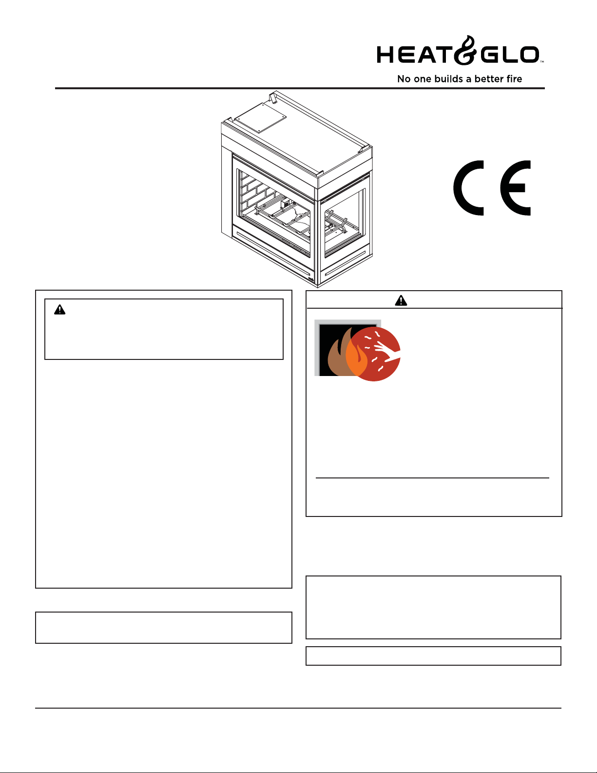
Models:
PIER-HVB-CE
ST-HVB-CE
LCOR-HVB-CE
RCOR-HVB-CE
Installers Guide
0087
WARNING: If the information in these
instructions is not followed exactly, a fi re
or explosion may result causing property
damage, personal injury, or death.
• Do not store or use gasoline or other fl am-
mable vapors and liquids in the vicinity of
this or any other appliance.
• What to do if you smell gas
- Do not try to light any appliance
- Do not touch any electrical switch. Do not
use any phone in your building.
- Immediately call your gas supplier from a
neighbor’s phone. Follow the gas supplier’s instructions.
- If you cannot reach your gas supplier, call
the fi re department.
• Installation and service must be performed
by a qualifi ed installer , service agency , or the
gas supplier.
This is a room sealed appliance and no other ventilation is
required than what is provided.
WARNING
HOT SURFACES!
Glass and other surfaces are hot during
operation AND cool down.
Hot glass will cause burns.
• DO NOT touch glass until it is cooled
• NEVER allow children to touch glass
• Keep children away
• CAREFULLY SUPERVISE children in same room as
fi replace.
• Alert children and adults to hazards of high temperatures.
High temperatures may ignite clothing or other fl ammable
materials.
• Keep clothing, furniture, draperies and other fl ammable
materials away.
This appliance has been supplied with an integral barrier
to prevent direct contact with the fi xed glass panel. DO
NOT operate the appliance with the barrier removed.
READ THIS MANUAL BEFORE INSTALLING OR
OPERATING THIS APPLIANCE. THIS INSTALLERS
GUIDE MUST BE LEFT WITH APPLIANCE FOR FUTURE
REFERENCE.
These instructions are only valid if the following country symbol is
on the appliance. If this symbol is not present on the appliance,
it is necessary to refer to the technical instructions which will
provide the necessary information concerning the modifi cation
of the appliance to the conditions of use for the country.
These instructions are valid for the following countries: GB, IE
Printed in U.S.A. Copyright 2009
Î
Heat & Glo, a brand of Hearth & Home Technologies Inc.
7571 215
This product is covered by one or more of the following patents: (United States) 4,112,913; 4,408,594; 4,422,426; 4,424,792; 4,520,791; 4,793,322; 4,852,548;
4,875,464; 5,000,162; 5,016,609; 5,076,254 5,191,877; 5,218,953; 5,328,356; 5,429,495; 5,452,708; 5,542,407; 5,613,487; (Australia) 543790; 586383; (Canada)
1,123,296; 1,297,746; 2,195,264; (Mexico) 97-0457; (New Zealand) 200265; or other U.S. and foreign patents pending.
th
Street West, Lakeville, MN 55044, USA
Heat & Glo • PIER/ST/L&RCOR-HVB-CE • 2068-900 Rev. K • 6/09 1
Please contact your Heat & Glo dealer with any questions or
concerns. For the number of your nearest Heat & Glo dealer,
please visit www.heatnglo.com.
Page 2
Safety and Warning Information
READ and UNDERSTAND all instructions carefully
!
before starting the installation. FAILURE TO FOLLOW
these installation instructions may result in a possible
fi re hazard and will void the warranty.
Prior to the fi rst fi ring of the fi replace, READ the Using
!
Your Fireplace section of the Owners Guide.
DO NOT USE this appliance if any part has been
under water. Immediately CALL a qualifi ed service
!
technician to inspect the unit and to replace any part
of the control system and any gas control which has
been under water.
THIS UNIT IS NOT FOR USE WITH SOLID FUEL.
!
Installation and repair should be PERFORMED by a
qualifi ed service person. The appliance and fl ueing
!
system should be INSPECTED before initial use and at
least annually by a professional service person. More
frequent cleaning may be required due to excessive lint
from carpeting, bedding material, etc. It is IMPERATIVE
that the unit’s control compartment, burners, and
circulating air passageways BE KEPT CLEAN to
provide for adequate combustion and ventilation air.
Always KEEP the appliance clear and free from
!
combustible materials, petrol, and other fl ammable
vapors and liquids.
These units MUST use one of the flue systems
!
described in the Installing the Fireplace section of
the Installers Guide. NO OTHER flue systems or
components MAY BE USED.
This gas fi replace and fl ue assembly MUST fl ue directly
!
to the outside and MUST NEVER be attached to a
chimney serving a separate solid fuel burning appliance.
Each gas appliance MUST USE a separate fl ue system.
Common fl ue systems are PROHIBITED.
INSPECT the external fl ue cap on a regular basis to
!
make sure that no debris is interfering with the air fl ow.
The glass door assembly MUST be in place and
!
sealed, and the trim door assembly MUST be in place
on the fi replace before the unit can be placed into safe
operation.
DO NOT OPERATE this appliance with the glass
door removed, cracked, or broken. Replacement of
!
the glass door should be performed by a licensed or
qualifi ed service person. DO NOT strike or slam the
glass door.
The glass door assembly SHALL ONLY be replaced
!
as a complete unit, as supplied by the gas fi replace
manufacturer. NO SUBSTITUTE material may be
used.
NEVER OBSTRUCT the flow of combustion and
!
ventilation air. Keep the front of the appliance CLEAR
of all obstacles and materials for servicing and proper
operations.
Due to the high temperature, the appliance should be
!
LOCATED out of traf
and draperies. Clothing or fl ammable material SHOULD
NOT BE PLACED on or near the appliance.
Children and adults should be ALERTED to the hazards
!
of high surface temperature and should STAY AWAY to
avoid burns or clothing ignition. Young children should
be CAREFULLY SUPERVISED when they are in the
same room as the appliance.
fi c areas and away from furniture
DO NOT USE abrasive cleaners on the glass door
!
assembly. DO NOT ATTEMPT to clean the glass door
when it is hot.
Turn off the gas before servicing this appliance. It
!
is recommended that a qualifi ed service technician
perform an appliance check-up at the beginning of
each heating season.
Any safety screen or guard removed for servicing must
!
be replaced before operating this appliance.
DO NOT place furniture or any other combustible
!
household objects within 36 inches of the fi replace
front.
This appliance is intended for use on a gas installation
!
with a governed meter.
2
Heat & Glo • PIER/ST/L&RCOR-HVB-CE • 2068-900 Rev. K • 6/09
Page 3

Table of Contents
Safety and Warning Information ..................................................2
Service Parts List ..........................................................................4
Section 1: Approvals and Regulations .....................................13
Appliance Certifi cation .................................................................................13
Installation Regulations ................................................................................ 13
Section 2: Getting Started .........................................................13
Introducing the Heat & Glo Gas Fireplaces .................................................13
Pre-install Preparation .................................................................................13
Section 3: Installing the Fireplace ............................................17
Step 1. Locating the Fireplace ....................................................................17
Step 2. Framing the Fireplace .....................................................................17
Step 3. Installing the Flue System ..............................................................20
A. Flue System Approvals .......................................................... 20
B. Installing Flue Components ................................................... 27
C. Flue Termination .................................................................... 29
Step 4. Positioning, Leveling, and Securing the Fireplace ..........................32
Step 5. The Gas Control System ................................................................32
Step 6. The Gas Supply Line ...................................................................... 33
Step 7. Gas Pressure Requirements ..........................................................33
Step 8. Wiring the Fireplace ........................................................................34
Step 9. Finishing .........................................................................................34
Step 10. Installing Trim, Logs & Ember Material .......................................... 35
Installing the Trim ..........................................................................35
Positioning the Logs ...................................................................... 35
Attachment of Lower Door Assembly ............................................ 35
Placing the Ember Material ........................................................... 40
Step 11. Before Lighting the Fireplace ....................................................... 41
Step 12. Lighting the Fireplace ...................................................................41
After the Installation .....................................................................................41
Section 4: Maintaining and Servicing Your Fireplace .............42
Section 5: Troubleshooting .......................................................43
Limited Lifetime Warranty ............................................................................46
Î
Î = Contains updated information
Heat & Glo • PIER/ST/L&RCOR-HVB-CE • 2068-900 Rev. K • 6/09 3
Page 4
Service Parts List
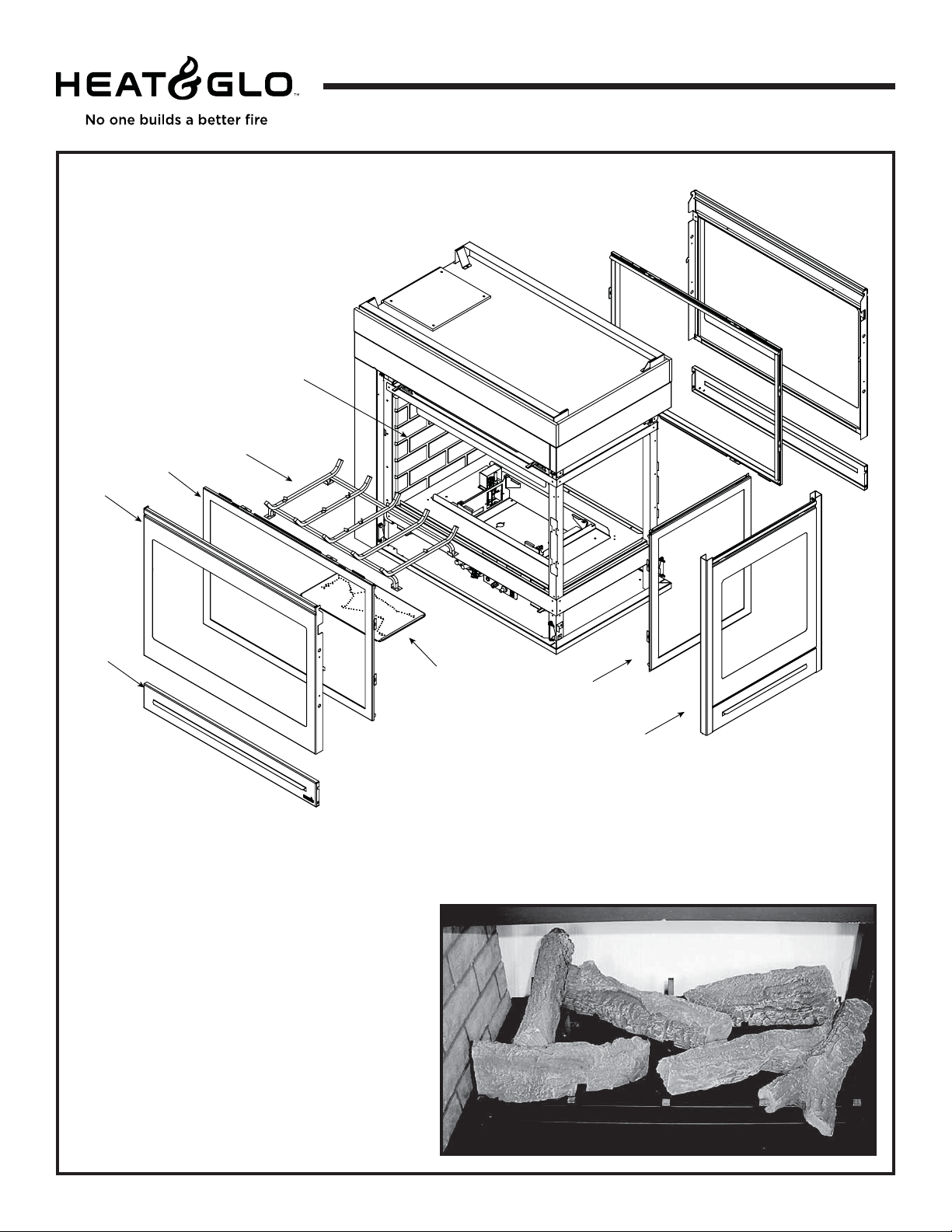
PIER-HVB-CE
Service Parts Diagram
1
2
3
4
Beginning Manufacturing Date: 6-04
Ending Manufacturing Date:______
5
6
7
8
Log Set Assembly
* Part number list on following page.
4
Heat & Glo • PIER/ST/L&RCOR-HVB-CE • 2068-900 Rev. K • 6/09
Page 5

Service parts list PIER-HVB-CE
IMPORTANT: THIS IS DATED INFORMATION. When requesting service or replacement parts for your appliance please
provide model number and serial number. All parts listed in this manual may be ordered from an authorized dealer.
ITEM DESCRIPTION COMMENTS PART NUMBER
Log Set Assembly
1 Refractory (Side)
2 Grate Assembly
3 Glass Assembly (Side)
4 Dress Guard Assembly 2068-040
5 Lower Door 2068-041
Burner N
6
Burner P & B
7 Glass Assembly (End)
8 End Panel Assembly 2069-042
Orifi ce N (#33DMS)
Orifi ce P (#51DMS)
Orifi ce B (#53DMS)
Non-combustible Board (Side)
Non-combustible Board (Back)
Junction Box
Bracket Junction Box
Mesh Assembly (End)
Mesh Assembly (Side)
Door Stop
Glass Latch Assembly
Fiber Glass Rope
Hood, Side, Black
Hood, End, Black
Fan Kit
Wall Thermostat Kit
Wall Switch kit, Off White
Wall Switch Kit, White
Mineral Wool
Lava Rock
Touch Up Paint
Conversion Kit N NGK-ST-CE
Conversion Kit P LPK-ST-CE
Conversion Kit B BGK-ST-CE
Pilot Orifi ce N 529-512
Pilot Orifi ce P 200-2630
Regulator N 230-1570
Regulator P & B 230-1520
Additional service part numbers appear on following page.
LOGS-ST-CE
SRV2005-730
2068-020
GLA-6TROC
2068-011
2068-013
GLA-MS
582-833
582-851
582-853
2006-136
2006-137
546-250A
2068-106
561-330A
537-300
2068-144
386-122A
060-455
SRV2005-190
SRV2006-194
GFK-240V
MV-STAT
WSK-21
WSK-21-W
050-721
2005-790
TUP-GBK-12
Heat & Glo • PIER/ST/L&RCOR-HVB-CE • 2068-900 Rev. K • 6/09 5
Page 6
Service Parts List
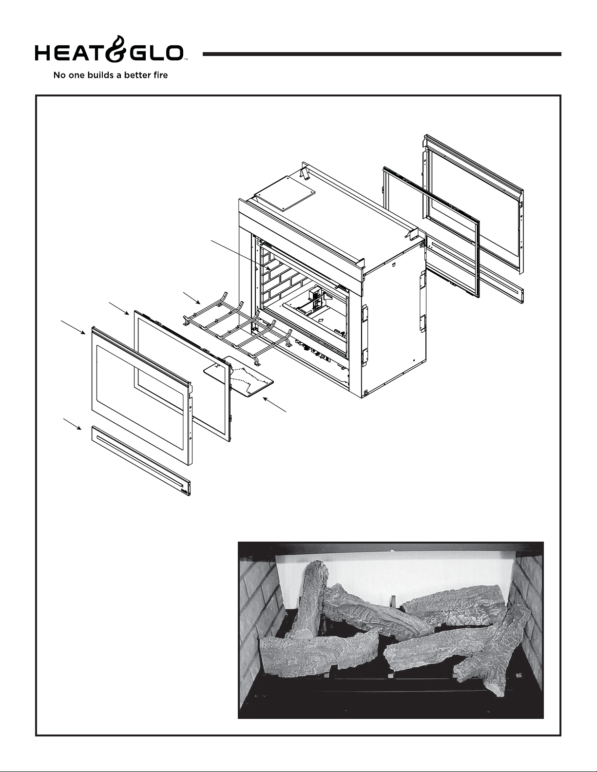
ST-HVB-CE
Service Parts Diagram
1
2
3
4
Beginning Manufacturing Date: 6-04
Ending Manufacturing Date:______
5
* Part number list on following page.
6
Log Set Assembly
6
Heat & Glo • PIER/ST/L&RCOR-HVB-CE • 2068-900 Rev. K • 6/09
Page 7

Service parts list ST-HVB-CE
IMPORTANT: THIS IS DATED INFORMATION. When requesting service or replacement parts for your appliance please
provide model number and serial number. All parts listed in this manual may be ordered from an authorized dealer.
ITEM DESCRIPTION SERIAL # PART NUMBER
Log Set Assembly
1 Refractory
2 Grate Assembly
3 Glass Assembly (Side)
4 Dress Guard Assembly 2068-040
5 Lower Door 2068-041
Burner N
6
Burner P & B
Orifi ce N (#33DMS)
Orifi ce P (#51DMS)
Orifi ce B (#53DMS)
Non-combustible Board
Junction Box
Bracket Junction Box
Mesh Assembly
Door Stop
Glass Latch Assembly
Fiber Glass Rope
Hood, End, Black
Fan Kit
Wall Thermostat Kit
Wall Switch kit, Off White
Wall Switch Kit, White
Mineral Wool
Lava Rock
Touch Up Paint
LOGS-ST-CE
SRV2005-730
2068-020
GLA-6TROC
2068-011
2068-013
582-833
582-851
582-853
2006-136
546-250A
2068-106
537-300
2068-144
386-122A
060-455
SRV2006-194
GFK-240V
MV-STAT
WSK-21
WSK-21-W
050-721
2005-790
TUP-GBK-12
Conversion Kit N NGK-ST-CE
Conversion Kit P LPK-ST-CE
Conversion Kit B BGK-ST-CE
Pilot Orifi ce N 529-512
Pilot Orifi ce P 200-2630
Regulator N 230-1570
Regulator P & B 230-1520
Additional service part numbers appear on following page.
Heat & Glo • PIER/ST/L&RCOR-HVB-CE • 2068-900 Rev. K • 6/09 7
Page 8
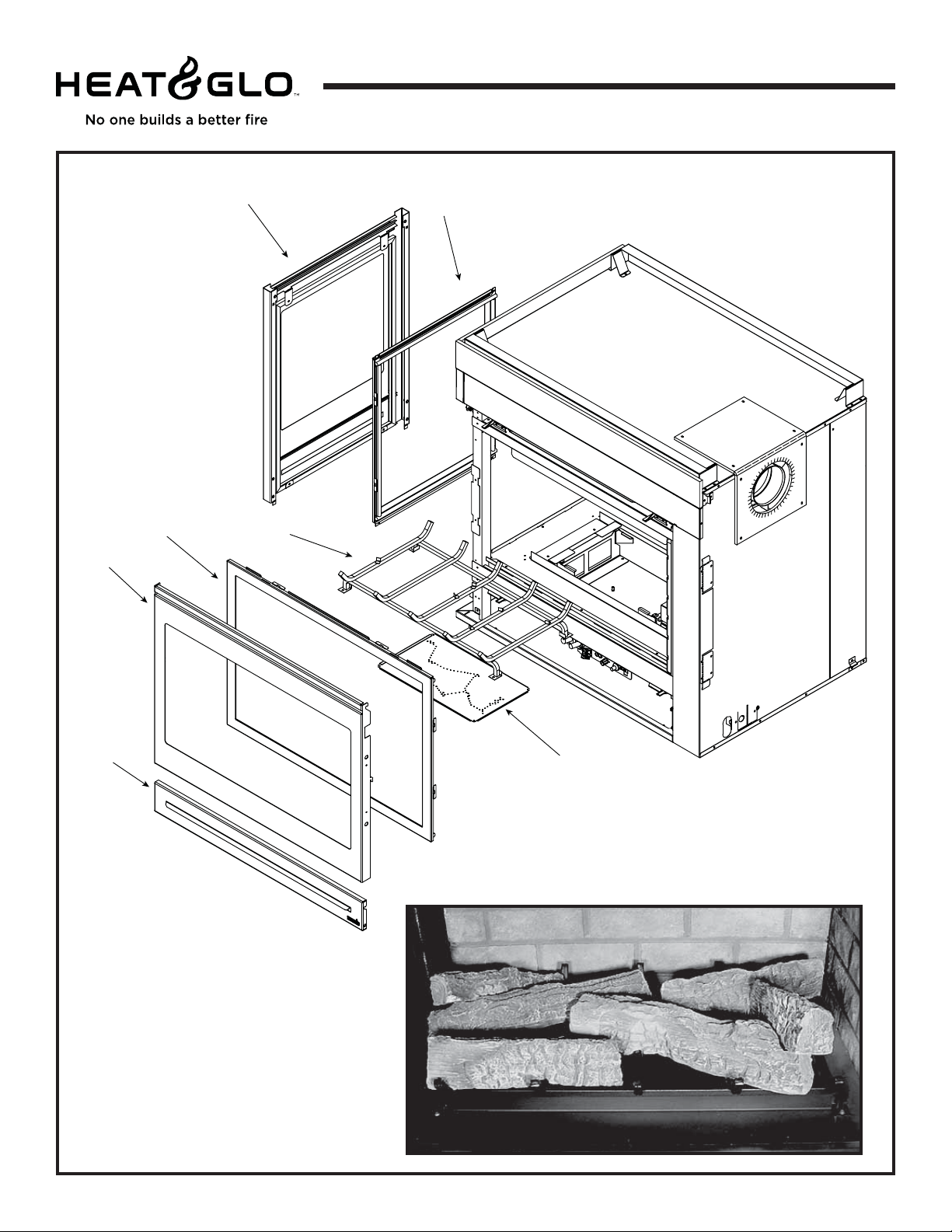
Service Parts List
LCOR-HVB-CE
Service Parts Diagram
2
4
5
3
1
Beginning Manufacturing Date: 6-04
Ending Manufacturing Date:______
6
* Part number list on following page.
8
7
Log Set Assembly
Heat & Glo • PIER/ST/L&RCOR-HVB-CE • 2068-900 Rev. K • 6/09
Page 9

Service parts list LCOR-HVB-CE
IMPORTANT: THIS IS DATED INFORMATION. When requesting service or replacement parts for your appliance please
provide model number and serial number. All parts listed in this manual may be ordered from an authorized dealer.
ITEM DESCRIPTION COMMENTS PART NUMBER
Log Set Assembly
1 Glass Assembly (End)
2 End Panel Assembly 2069-042
3 Grate Assembly
4 Glass Assembly (Side)
5 Dress Guard Assembly 2068-040
6 Lower Door 2068-041
Burner N
7
Burner P & B
Orifi ce N (#33DMS)
Orifi ce P (#51DMS)
Orifi ce B (#53DMS)
Refractory (Side)
Refractory (End)
Non-combustible Board (Side)
Non-combustible Board (Back)
Junction Box
Bracket Junction Box
Mesh Assembly (End)
Mesh Assembly (Side)
Door Stop
Glass Latch Assembly
Fiber Glass Rope
Hood, Side, Black
Hood, End, Black
Fan Kit
Wall Thermostat Kit
Wall Switch kit, Off White
Wall Switch Kit, White
Mineral Wool
Lava Rock
Touch Up Paint
Conversion Kit N NGK-ST-CE
Conversion Kit P LPK-ST-CE
Conversion Kit B BGK-ST-CE
Pilot Orifi ce N 529-512
Pilot Orifi ce P 200-2630
Regulator N 230-1570
Regulator P & B 230-1520
Additional service part numbers appear on following page.
LOGS-ST-CE
GLA-MS
2068-020
GLA-6TROC
2068-011
2068-013
582-833
582-851
582-853
SRV2005-730
SRV7005-731
2006-136
2006-137
546-250A
2068-106
561-330A
537-300
2068-144
386-122A
060-455
SRV2005-190
SRV2006-194
GFK-240V
MV-STAT
WSK-21
WSK-21-W
050-721
2005-790
TUP-GBK-12
Heat & Glo • PIER/ST/L&RCOR-HVB-CE • 2068-900 Rev. K • 6/09 9
Page 10
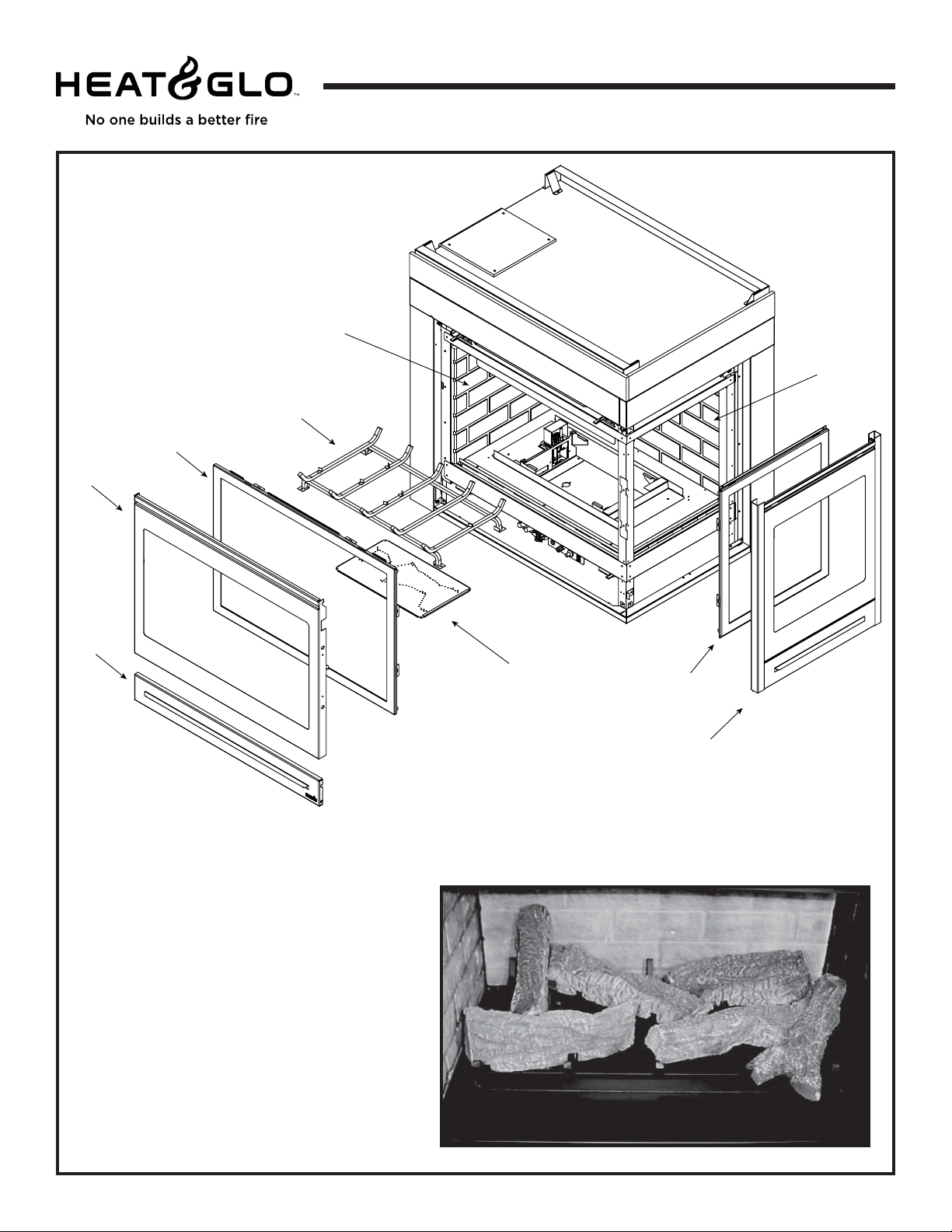
Service Parts List
RCOR-HVB-CE
Service Parts Diagram
1
2
3
4
Beginning Manufacturing Date: 6-04
Ending Manufacturing Date:______
9
5
6
7
8
Log Set Assembly
10
* Part number list on following page.
Heat & Glo • PIER/ST/L&RCOR-HVB-CE • 2068-900 Rev. K • 6/09
Page 11

Service parts list RCOR-HVB-CE
IMPORTANT: THIS IS DATED INFORMATION. When requesting service or replacement parts for your appliance please
provide model number and serial number. All parts listed in this manual may be ordered from an authorized dealer.
ITEM DESCRIPTION COMMENTS PART NUMBER
Log Set Assembly
1 Refractory (End)
2 Grate Assembly
3 Glass Assembly (Side)
4 Dress Guard Assembly 2068-040
5 Lower Door 2068-041
Burner N
6
Burner P & B
7 Glass Assembly (End)
8 End Panel Assembly 2069-042
9 Refractory (Side)
Orifi ce N (#33DMS)
Orifi ce P (#51DMS)
Orifi ce B (#53DMS)
Non-combustible Board (Side)
Non-combustible Board (Back)
Junction Box
Bracket Junction Box
Mesh Assembly (End)
Mesh Assembly (Side)
Door Stop
Glass Latch Assembly
Fiber Glass Rope
Hood, Side, Black
Hood, End, Black
Fan Kit
Wall Thermostat Kit
Wall Switch kit, Off White
Wall Switch Kit, White
Mineral Wool
Lava Rock
Touch Up Paint
Conversion Kit N NGK-ST-CE
Conversion Kit P LPK-ST-CE
Conversion Kit B BGK-ST-CE
Pilot Orifi ce N 529-512
Pilot Orifi ce P 200-2630
Regulator N 230-1570
Regulator P & B 230-1520
Additional service part numbers appear on following page.
LOGS-ST-CE
SRV7005-731
2068-020
GLA-6TROC
2068-011
2068-013
GLA-MS
SRV2005-730
582-833
582-851
582-853
2006-136
2006-137
546-250A
2068-106
561-330A
537-300
2068-144
386-122A
060-455
SRV2005-190
SRV2006-194
GFK-240V
MV-STAT
WSK-21
WSK-21-W
050-721
2005-790
TUP-GBK-12
Heat & Glo • PIER/ST/L&RCOR-HVB-CE • 2068-900 Rev. K • 6/09 11
Page 12
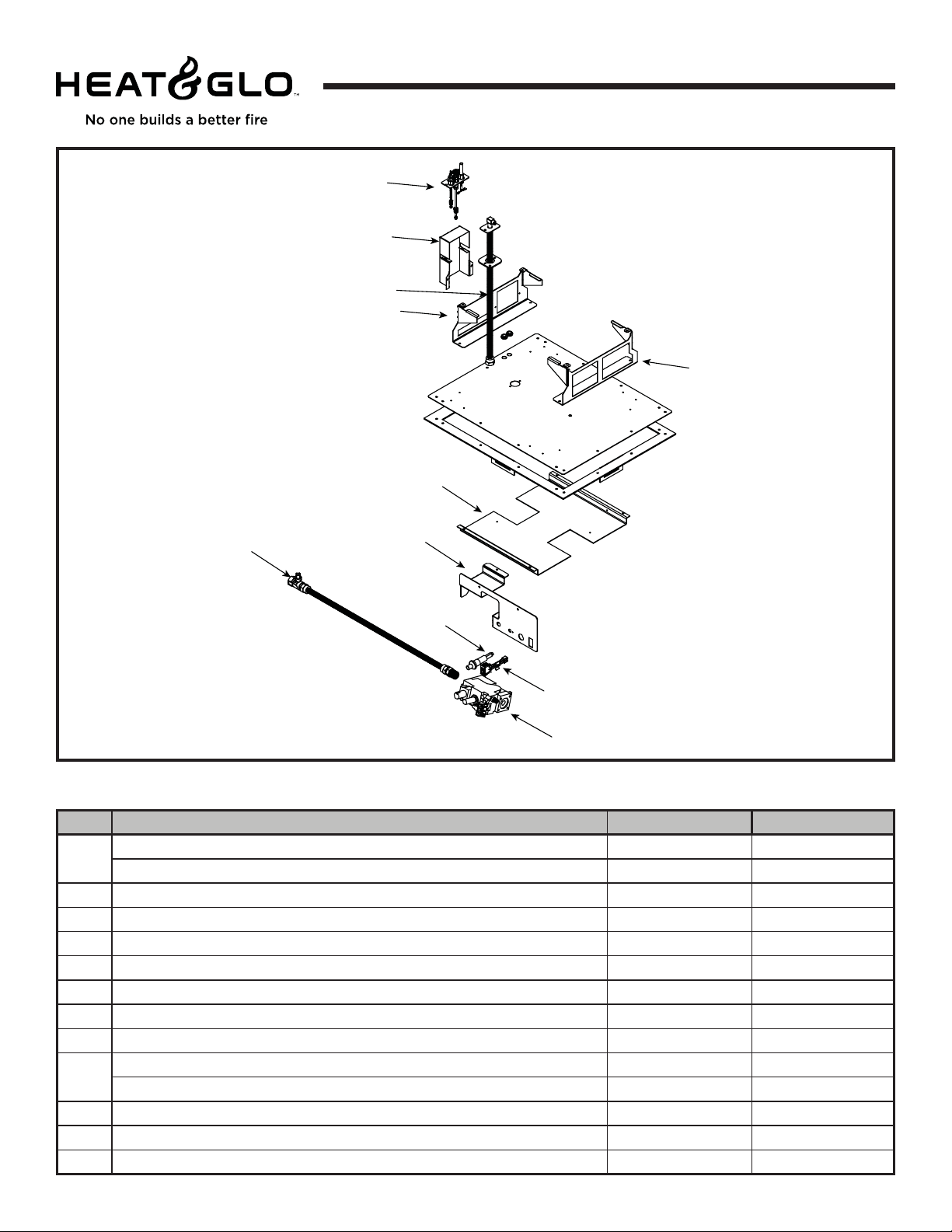
Service Parts List
PIER-HVB-CE, ST-HVB-CE, L&RCOR-HVB-CE
Valve Assembly
Standing Pilot Valve Assembly
8
Beginning Manufacturing Date: 6-04
Ending Manufacturing Date: ______
1
2
3
4
11
5
6
7
10
9
IMPORTANT: THIS IS DATED INFORMATION. When requesting service or replacement parts for your appliance please
provide model number and serial number. All parts listed in this manual may be ordered from an authorized dealer.
ITEM DESCRIPTION COMMENTS PART NUMBER
Pilot Assembly N 529-540A
1
Pilot Assembly P 529-541A
2 Pilot Bracket 2068-114
3 Flexible Gas Connector
4 Burner Leg, Pilot Support 2068-112
5 Universal Bracket 2068-111
6 Valve Bracket 2068-115
7 Piezo Ignitor
8 Flex Ball Valve Assembly
Valve N 060-524
9
Valve P 060-526
10 On/ Off Wire Assembly
11 Burner Leg 2068-113
20" Wire Harness
530-302A
291-513
302-330A
060-521A
107-559A
12
Heat & Glo • PIER/ST/L&RCOR-HVB-CE • 2068-900 Rev. K • 6/09
Page 13

1
Approvals and Regulations
Appliance Certifi cation
The Heat & Glo fi replace models discussed in this Installers
Guide have been tested to certifi cation standards and listed
by the applicable laboratories.
Certifi cation
MODELS: PIER-HVB-CE, ST-HVB-CE,
LCOR-HVB-CE, RCOR-HVB-CE
LABORATORY: Advantica
TYPE: Gas Fireplace
STANDARD: BS EN 613:2001
DIRECTIVE: GAD90/396/EEC
Getting Started
2
Introducing the Heat & Glo Gas Fireplaces
Heat & Glo direct fl ue gas fi replaces are designed to oper-
ate with all combustion air siphoned from outside of the
building and all exhaust gases expelled to the outside.
The information contained in this Installers Guide, unless
noted otherwise, applies to all models and gas control
systems. Gas fi replace diagrams, including the dimensions,
are shown in this section.
Pre-install Preparation
This gas fi replace and its components are tested and safe
when installed in accordance with this Installers Guide.
Report to your dealer any parts damaged in shipment,
particularly the condition of the glass. Do not install any
unit with damaged, incomplete, or substitute parts.
The fl ue system components are shipped in separate pack-
ages. The gas logs are packaged separately and must be
fi eld installed.
Read all of the instructions before starting the installation. Follow these instructions carefully during the
installation to ensure maximum safety and benefi t. Fail-
ure to follow these instructions will void the owner’s
warranty and may present a fi re hazard.
Installation Regulations
Before installation check that local distribution conditions,
nature of gas and pressure, and adjustment of the
appliance are compatible.
This appliance must be installed with the rules in force,
and used only in a suffi ciently ventilated space. Consult
instructions before installation and use of this appliance.
The Heat & Glo Warranty will be voided by , and Heat & Glo
disclaims any responsibility for, the following actions:
• Installation of any damaged fi replace or fl ue system
component.
• Modifi cation of the fi replace or direct fl ue system.
• Installation other than as instructed by Heat & Glo.
• Improper positioning of the gas logs or the glass door.
• Installation and/or use of any component part not manufactured and approved by Heat & Glo, not withstanding
any independent testing laboratory or other party approval of such component part or accessory.
ANY SUCH ACTION MAY POSSIBLY CAUSE A FIRE
HAZARD.
When planning a fi replace installation, it’s necessary
to determine:
• Where the unit is to be installed.
• The fl ue system confi guration to be used.
• Gas supply piping.
• Electrical wiring.
• Framing and fi nishing details.
• Whether optional accessories—devices such as a fan,
wall switch, or remote control—are desired.
If the fi replace is to be installed on carpeting, tile or
any combustible material other than wood fl ooring,
it should be installed on a metal or wood panel that
extends the full width and depth of the fi replace.
Heat & Glo • PIER/ST/L&RCOR-HVB-CE • 2068-900 Rev. K • 6/09 13
Page 14
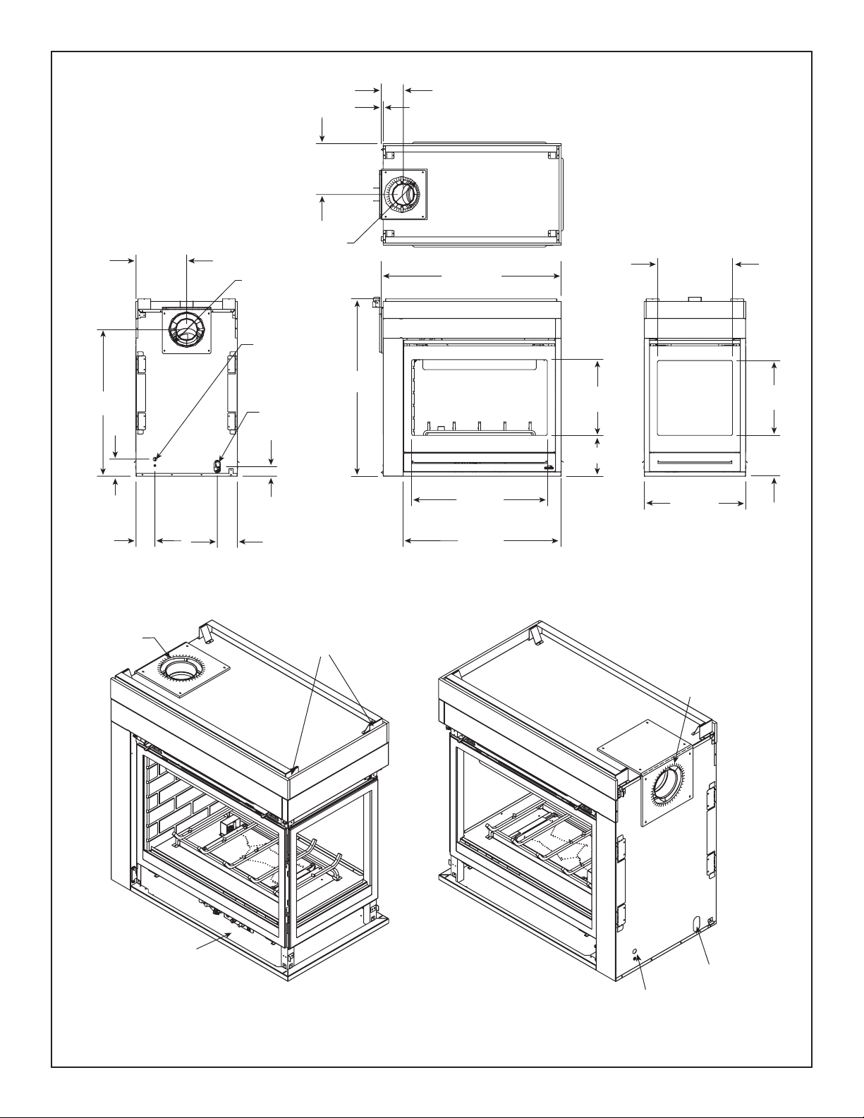
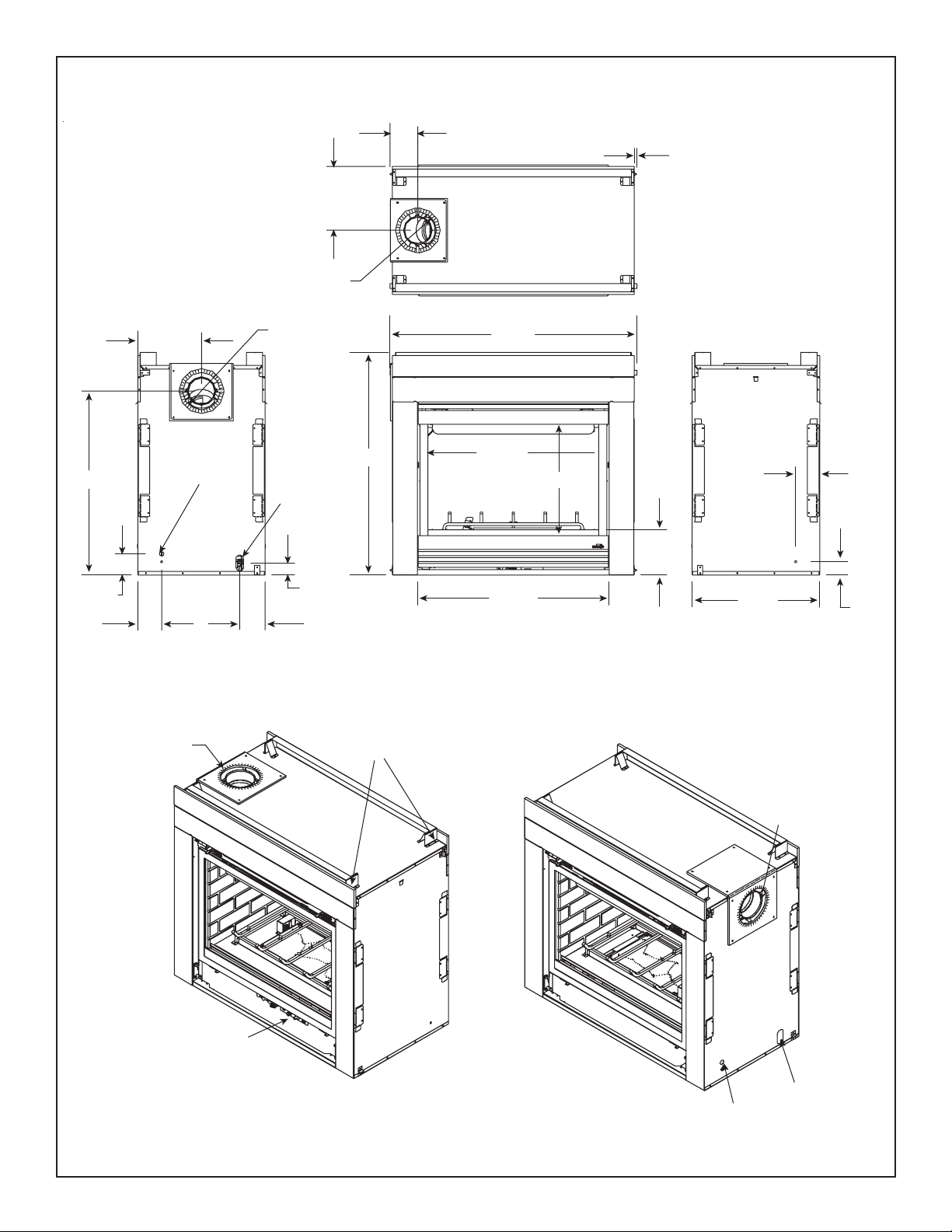
882 mm
305 mm
Ø 204 mm
Ø 204 mm
ELECTRICAL
ACCESS
GAS LINE
ACCESS
306 mm
1067 mm
133 mm
13 mm
1082 mm
456 mm
451 mm
451 mm
102 mm
114 mm
TOP FLUE
COLLARS
58 mm
121 mm
TOP STANDOFFS
816 mm
950 mm
245 mm
245 mm
610 mm
REAR FLUE
COLLARS
GAS CONTROLS
AND LABELS
Figure 1. Diagram of the PIER-HVB-CE
14
Heat & Glo • PIER/ST/L&RCOR-HVB-CE • 2068-900 Rev. K • 6/09
GAS LINE
ACCESS
ELECTRICAL
ACCESS
Page 15
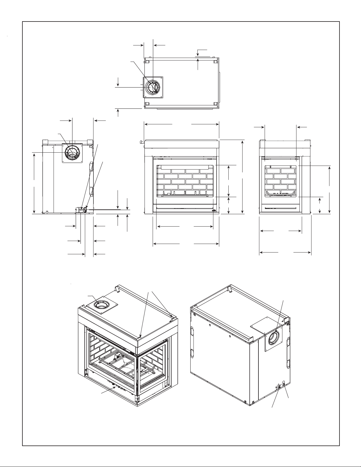
306 mm
Ø204 mm
133 mm
13 mm
882 mm
102 mm
114 mm
305 mm
ELECTRICAL
TOP FLUE
COLLARS
ACCESS
Ø204 mm
GAS LINE
ACCESS
58 mm
121 mm
1067 mm
TOP STANDOFFS
1183 mm
820 mm
919 mm
533 mm
216 mm
610 mm
114 mm
64 mm
GAS CONTROLS
AND LABELS
Figure 2. Diagram of the ST-HVB-CE
Heat & Glo • PIER/ST/L&RCOR-HVB-CE • 2068-900 Rev. K • 6/09 15
ELECTRICAL
ACCESS
REAR FLUE
COLLARS
GAS LINE
ACCESS
Page 16
133 mm
Ø 204 mm
306 mm
13 mm
882 mm
305 mm
Ø 204 mm
254 mm
184 mm
121 mm
TOP FLUE
COLLARS
ELECTRICAL
ACCESS
GAS LINE
ACCESS
64 mm
58 mm
TOP STANDOFFS
1082 mm
816 mm
950 mm
456 mm
245 mm
1067 mm
451 mm
612 mm
743 mm
REAR FLUE
COLLARS
456 mm
245 mm
GAS CONTROLS
AND LABELS
Figure 3. Diagram of the LCOR-HVB-CE and RCOR-HVB-CE
16
Heat & Glo • PIER/ST/L&RCOR-HVB-CE • 2068-900 Rev. K • 6/09
ELECTRICAL
ACCESS
GAS LINE
ACCESS
Page 17
3
Installing the Fireplace
Step 1. Locating the Fireplace
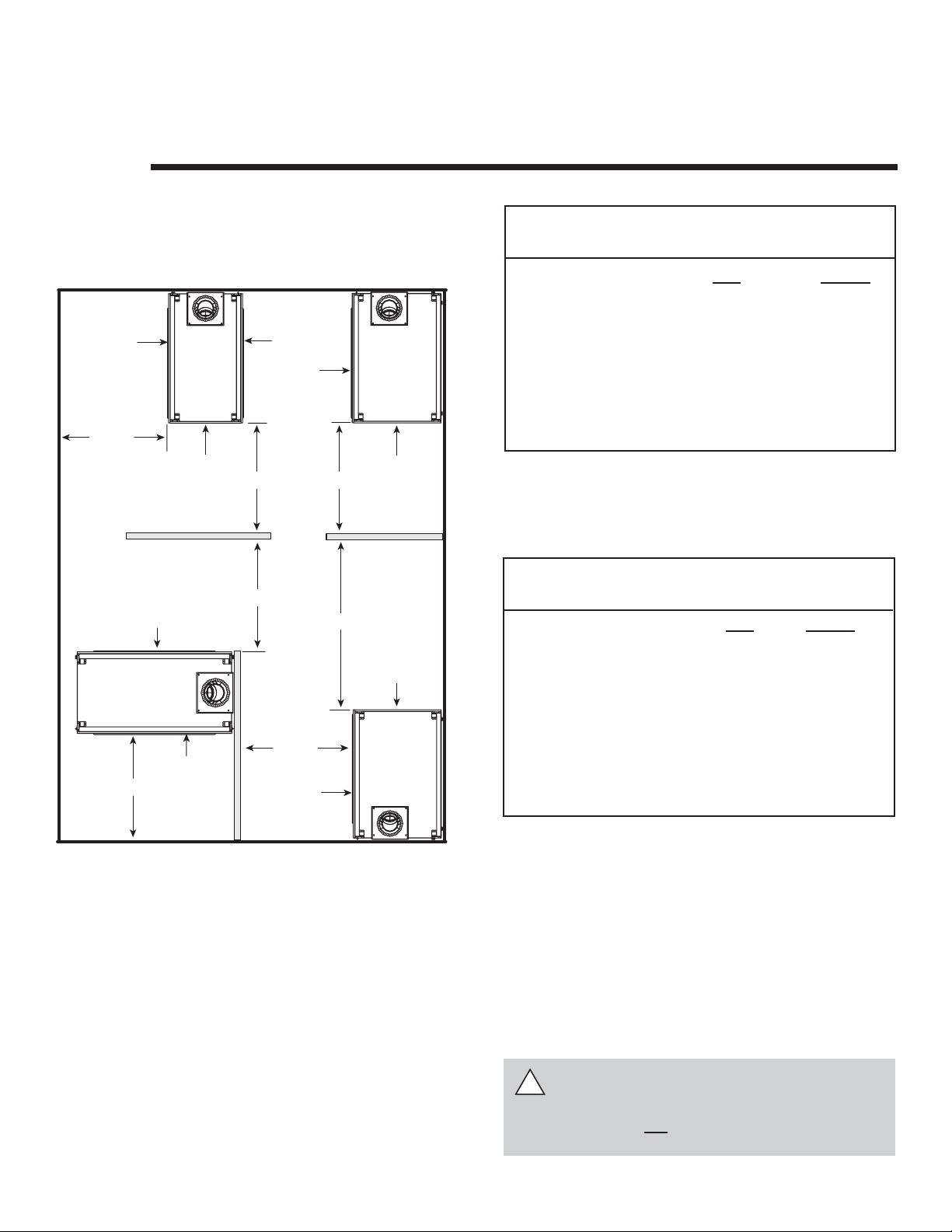
The diagram below shows space and clearance requirements for locating a fi replace within a room.
GLASS
914 mm
ST-HVB-CE
TOP VIEW
914 mm
GLASS
GLASS
GLASS
PIER-HVB-CE
TOP VIEW
914 mm
914 mm
GLASS
GLASS
914 mm
914 mm
914 mm
GLASS
RCOR-HVB-CE
TOP VIEW
GLASS
GLASS
LCOR-HVB-CE
TOP VIEW
Minimum Clearances
from the Fireplace to Combustible Materials
mm inches
Glass Sides or Ends ..........914 .....................36
Floor ....................................0 ........................ 0
Rear Flue ............................13 ......................1/2
Metal Sides or Ends ...........13 ......................1/2
Top ......................................64 .................... 2 1/2
Ceiling* ..............................787 .....................31
* The clearance to the ceiling is measured from the top of
the unit, excluding the standoffs (see Figures 37 & 38).
The distance from the unit to combustible construction is
to be measured from the unit outer wrap surface to the
combustible construction, NOT from the screw heads that
secure the unit together.
Minimum Clearances
from the Flue Pipe to Combustible Materials
mm Inches
Vertical Sections. .............25 .................1
Horizontal Sections
Top .....................................75 .................3
Bottom ...............................25 .................1
Sides..................................25 .................1
At Wall Firestops
Top ................................... 63.7 .............2 1/2
Bottom ...............................13 ............... 1/2
Sides..................................25 .................1
Figure 4. Fireplace Dimensions and Locations
Clearance Requirements
The top, back, and sides of the fi replace are defi ned by
stand-offs. The minimum clearance to a perpendicular wall
extending past the face of the fi replace is 25 mm (1 in.).
The metal ends of the fi replace may NOT be recessed into
combustible construction.
Heat & Glo • PIER/ST/L&RCOR-HVB-CE • 2068-900 Rev. K • 6/09 17
For minimum clearances, see the direct fl ue termination
clearance diagrams on pages 30 and 31 in this manual.
Step 2. Framing the Fireplace
Fireplace framing can be built before or after the fi replace is
set in place. Framing should be positioned to accommodate
wall coverings and fi replace facing material. The diagram
below shows framing reference dimensions.
CAUTION: MEASURE FIREPLACE DIMENSIONS AND
VERIFY FRAMING METHODS AND WALL COVERING
DETAILS BEFORE FRAMING.
WARNING: FRAMING DIMENSIONS ASSUME
!
USE OF 1/2 INCH THICK WALL COVERING
MATERIALS ON EXTERIOR OF FRAMING
ONLY AND NO SHEETROCK ON INTERIOR
OF FRAMING.
Page 18
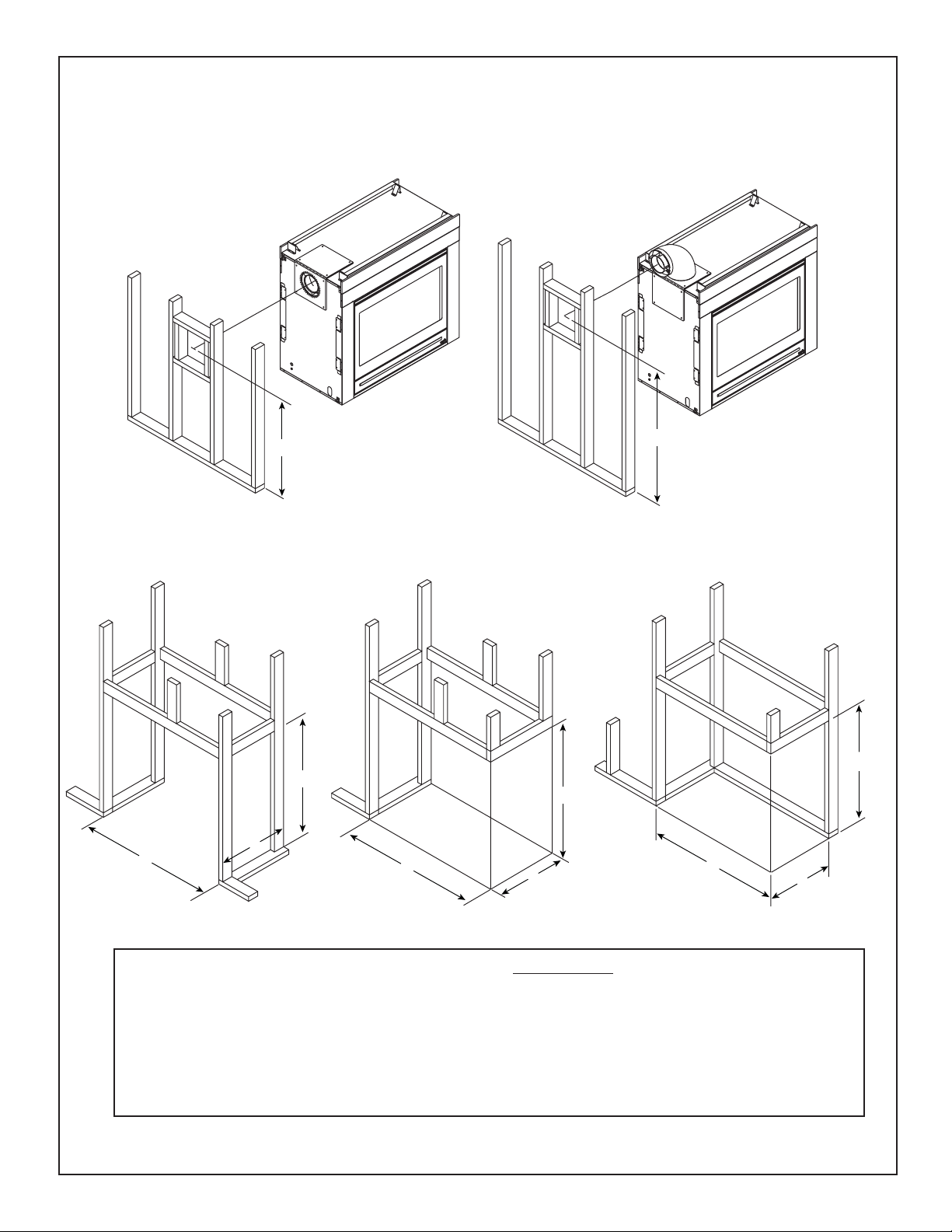
Shows center of 254mm x 305mm (10”x12”) fl ue framing holes for top and rear fl ueing.
The center of the hole is 25.4mm (one inch) above the center of the horizontal fl ue pipe.
D
Framing should be constructed
of 51 mm x 102 mm (2 in. x 4 in.)
lumber or heavier.
ST-HVB-CE L & R-COR-HVB-CE
PIER-HVB-CE
E
B
B
B
C
A
A
C
A
C
Model A B C D E
PIER-HVB-CE 107 (42-1/8) 108 (42-1/2) 58 (23) 91 (35-3/4) 122 (48)
ST-HVB-CE 121 (47-5/8) 108 (42-1/2) 58 (23) 91 (35-3/4) 122 (48)
L&RCOR-HVB-CE 107 (42-1/8) 108 (42-1/2) 73 (28-3/4) 91 (35-3/4) 122 (48)
Figure 5. Framing Dimensions
18
NOTE: DIMENSIONS SHOWN IN CENTIMETERS AND (INCHES).
Heat & Glo • PIER/ST/L&RCOR-HVB-CE • 2068-900 Rev. K • 6/09
Page 19
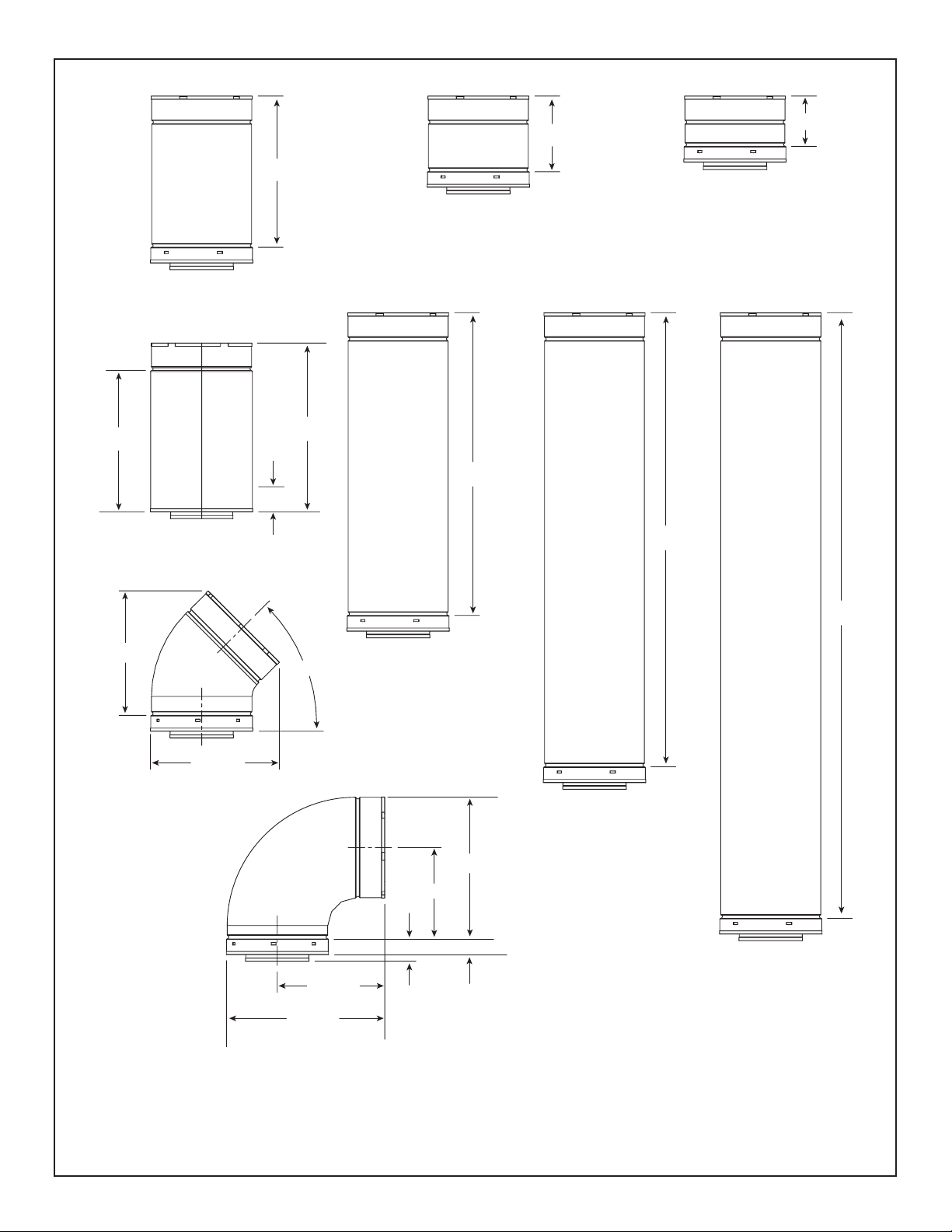
152 mm
102 mm
310 mm MAX.
DVP12
DVP12A
305 mm
362 mm
51 mm MIN.
DVP4
DVP6
610 mm
914 mm
1219 mm
251 mm
261 mm
DVP45
º
45
218 mm
320 mm
DVP90ST
DVP24
18 mm
185 mm
286 mm
32 mm
DVP36
DVP48
NOTE: PIPES OVERLAP 32 mm (1-1/4 in.) AT EACH JOINT.
Figure 6. DVP-Series Direct Flue Component Specifi cations (127 mm (5 in.) inner pipe / 203 mm (8 in.) outer pipe)
Heat & Glo • PIER/ST/L&RCOR-HVB-CE • 2068-900 Rev. K • 6/09 19
Page 20
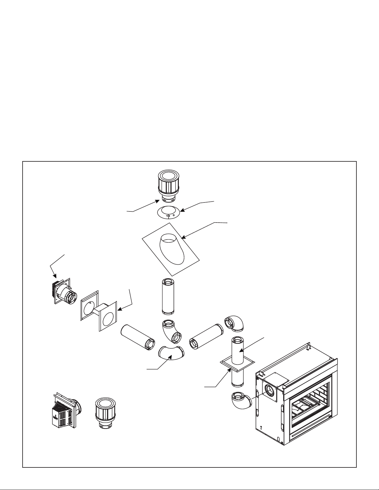
Step 3. Installing the Flue System
A. Flue System Approvals
These models are approved to use DVP series direct fl ue
pipe components and terminations (see Figures 6 and 7).
Approved fl ue system components are labeled for identifi -
cation. This pipe is tested and listed as an approved component of the fi replace. The pipe is tested to be run inside
an enclosed wall. There is no requirement for inspection
openings at each joint within the wall. There is no required
pitch for horizontal fl ue runs. NO OTHER FLUEING SYS-
TEMS OR COMPONENTS MAY BE USED.
Detailed installation instructions are included with each
fl ue termination kit and should be used in conjunction with
this Installers Guide.
The fl ame and ember appearance may vary based on the
type of fuel burned and the fl ueing confi guration used.
Identifying Flue Components
The fl ue systems installed on this gas fi replace may include
one, two, or three 90° elbow assemblies. The relationships
of vertical rise to horizontal run in fl ue confi gurations using
90° elbows MUST BE strictly adhered to. The rise to run
relationships are shown in the fl ueing drawings and tables.
Refer to the diagrams on the next several pages.
NOTE: Two 45° elbows may be used in place of one
90° elbow. Rise to run ratios in the fl ue system must
be followed if 45° elbows are used.
0
This model has a 45
elbow built into it. It may be positioned to fl ue either horizontal or vertical. Depending on
the installation, decide which direction the elbow should be
facing. Remove the 8 screws from the corner cover plate.
Position the 450 elbow as desired and replace the corner
cover plate with the 8 screws.
VERTICAL
TERMINATION
HORIZONTAL TERMINATION
WALL FIRESTOPS
90º ELBOW
STORM COLLAR
ROOF FLASHING
PIPE LENGTH
TERMINATION KITS
DVP-TRAP
DVP-TVHW
CEILING FIRESTOP
Figure 7. Flue System Components and Termination Kits
20
Heat & Glo • PIER/ST/L&RCOR-HVB-CE • 2068-900 Rev. K • 6/09
Page 21
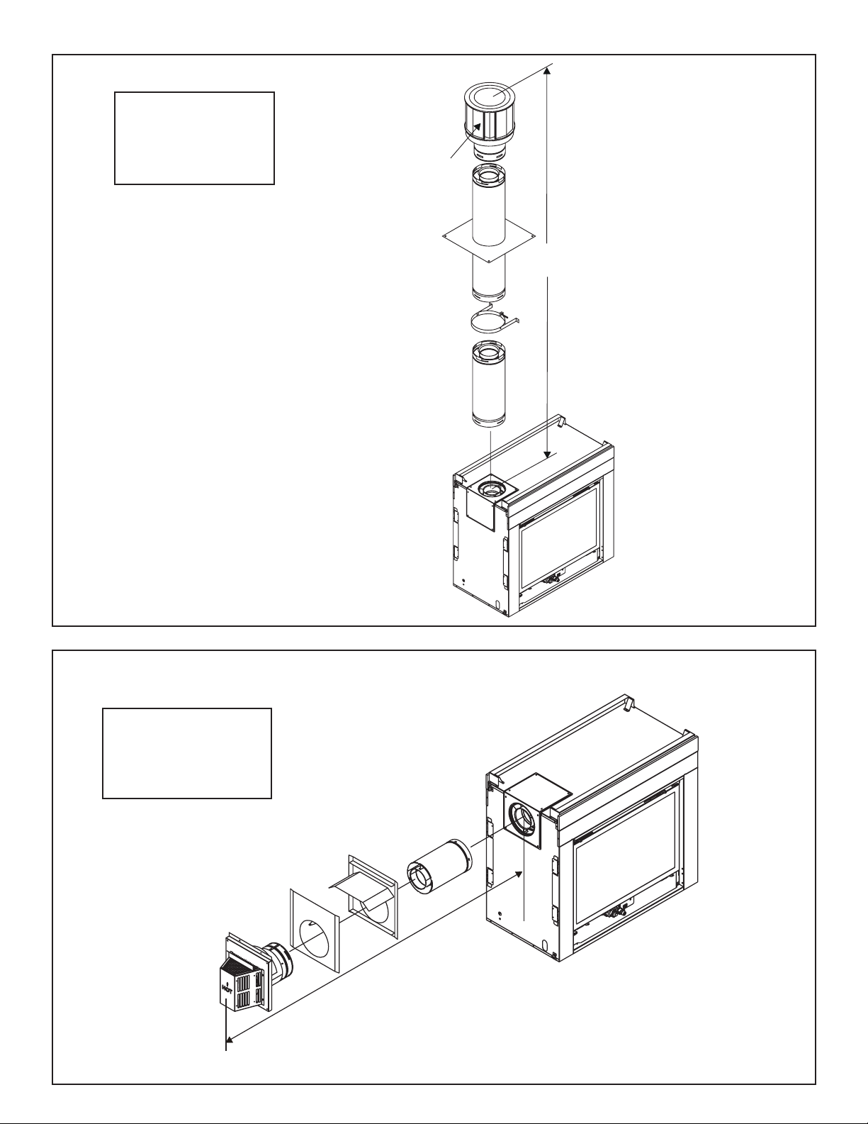
STRAIGHT UP
VERTICAL FLUEING
V (FT.)
12.2M MAX. (40 FT.)
TERMINATION CAP
V
Figure 8
STRAIGHT OUT
HORIZONTAL FLUEING
H
Max. Run
610 mm (24 in.)
H
Figure 9.
Heat & Glo • PIER/ST/L&RCOR-HVB-CE • 2068-900 Rev. K • 6/09 21
Page 22
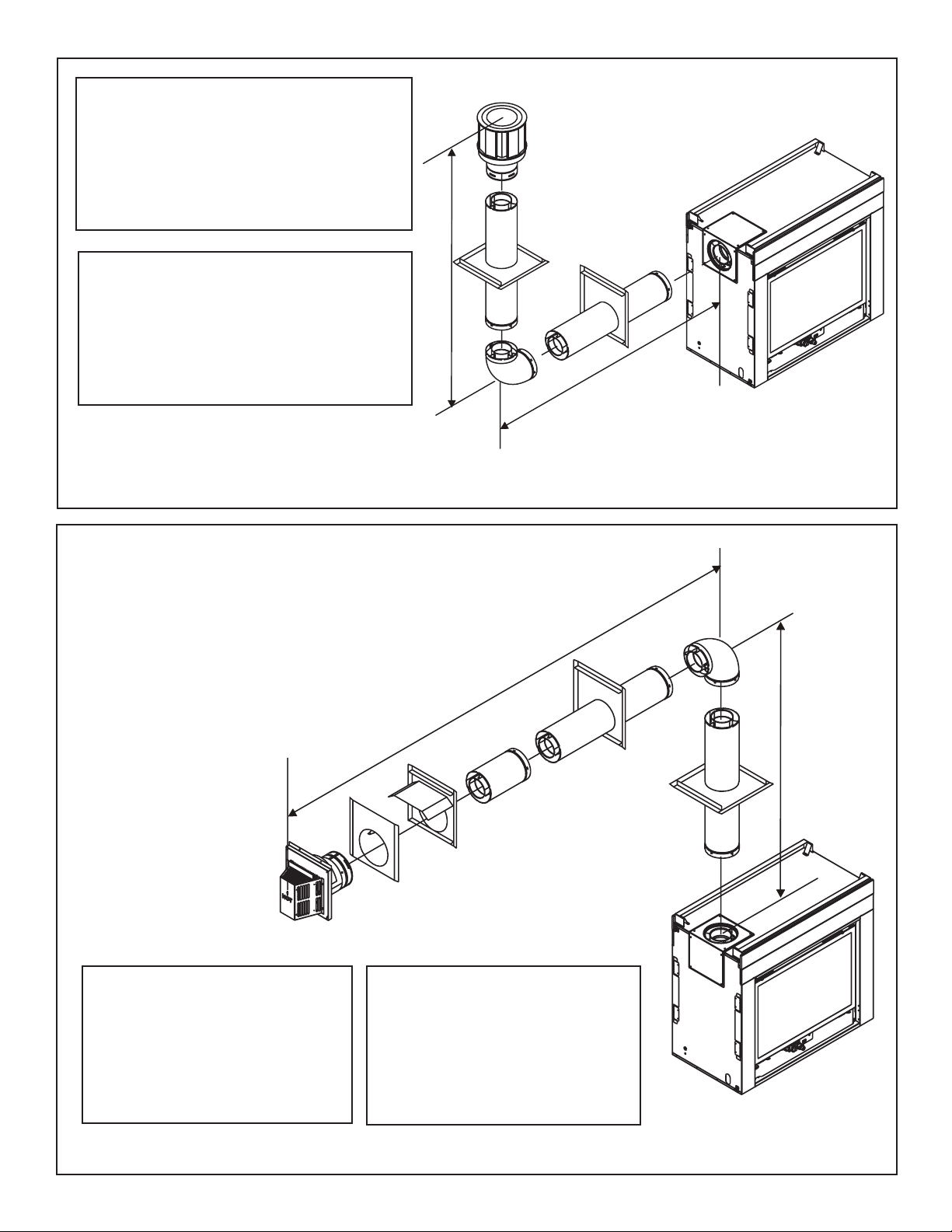
NATURAL GAS - FLUEING WITH ONE 90° ELBOW
V (FT.) H (FT.)
1’ MIN. (305 mm) 3’ MAX. (914 mm)
2’ MIN. (610 mm) 6’ MAX. (1.83 m)
3’ MIN. (914 mm) 9’ MAX. (2.7 m)
4’ MIN. (1.22 m) 12’ MAX. (3.6 m)
5’ MIN. (1.5 m) 15’ MAX. (4.5 m)
6’ MIN. (1.83 m) 18’ MAX. (5.5 m)
V + H = 40’ MAX. (12.2 m)
PROPANE / BUTANE - FLUEING WITH ONE 90° ELBOW
V (FT.) H (FT.)
1’ MIN. (305 mm) 2’ MAX. (610 mm)
2’ MIN. (610 mm) 4’ MAX. (1.22 m)
3’ MIN. (914 mm) 6’ MAX. (1.83 m)
4’ MIN. (1.22 m) 8’ MAX. (2.4 m)
5’ MIN. (1.5 m) 10’ MAX. (3.0 m)
6’ MIN. (1.83 m) 12’ MAX. (3.6 m)
V + H = 40’ MAX. (12.2 m)
Figure 10. Flueing with One 90° Elbow
V
H
NATURAL GAS
FLUEING WITH ONE 90° ELBOW
V (FT.) H (FT.)
1’ MIN. (305 mm) 3’ MAX. (914 mm)
2’ MIN. (610 mm) 6’ MAX. (1.83 m)
3’ MIN. (914 mm) 9’ MAX. (2.7 m)
4’ MIN. (1.22 m) 12’ MAX. (3.6 m)
5’ MIN. (1.5 m) 15’ MAX. (4.5 m)
V + H = 40’ MAX. (12.2 m)
H
V
PROPANE / BUTANE
FLUEING WITH ONE 90° ELBOW
V (FT.) H (FT.)
1’ MIN. (305 mm) 2’ MAX. (610 mm)
2’ MIN. (610 mm) 4’ MAX. (1.22 m)
3’ MIN. (914 mm) 6’ MAX. (1.83 m)
4’ MIN. (1.22 m) 8’ MAX. (2.4 m)
5’ MIN. (1.5 m) 10’ MAX. (3.0 m)
V + H = 40’ MAX. (12.2 m)
Figure 11. Flueing with One 90° Elbow
22
Heat & Glo • PIER/ST/L&RCOR-HVB-CE • 2068-900 Rev. K • 6/09
Page 23
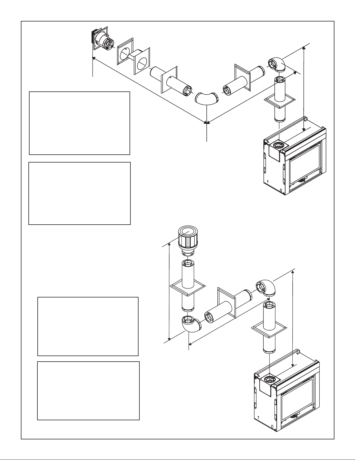
NATURAL GAS
FLUEING WITH TWO 90° ELBOWS
V (FT.) H + H
1’ MIN. (305 mm) 3’ MAX. (914 mm)
2’ MIN. (610 mm) 6’ MAX. (1.83 m)
3’ MIN. (914 mm) 9’ MAX. (2.7 m)
4’ MIN. (1.22 m) 12’ MAX. (3.6 m)
5’ MIN. (1.5 m) 15’ MAX. (4.5 m)
V + H + H1 = 40’ MAX. (12.2 m)
H + H
FLUEING WITH TWO 90° ELBOWS
= 15’ MAX. (4.5 m)
1
PROPANE / BUTANE
V (FT.) H + H
1’ MIN. (305 mm) 2’ MAX. (610 mm)
2’ MIN. (610 mm) 4’ MAX. (1.22 m)
3’ MIN. (914 mm) 6’ MAX. (1.83 m)
4’ MIN. (1.22 m) 8’ MAX. (2.4 m)
5’ MIN. (1.5 m) 10’ MAX. (3.0 m)
V + H + H
H + H1 = 10’ MAX. (3.0 m)
= 40’ MAX. (12.2 m)
1
1
1
(FT.)
(FT.)
H
1
V
H
NATURAL GAS
FLUEING WITH TWO 90° ELBOWS
V + V
(FT.) H (FT.)
1
1’ MIN. (305 mm) 3’ MAX. (914 mm)
2’ MIN. (610 mm) 6’ MAX. (1.83 m)
3’ MIN. (914 mm) 9’ MAX. (2.7 m)
4’ MIN. (1.22 m) 12’ MAX. (3.6 m)
5’ MIN. (1.5 m) 15’ MAX. (4.5 m)
V + V1 + H = 40’ MAX. (12.2 m)
PROPANE / BUTANE
FLUEING WITH TWO 90° ELBOWS
V + V
(FT.) H (FT.)
1
1’ MIN. (305 mm) 2’ MAX. (610 mm)
2’ MIN. (610 mm) 4’ MAX. (1.22 m)
3’ MIN. (914 mm) 6’ MAX. (1.83 m)
4’ MIN. (1.22 m) 8’ MAX. (2.4 m)
5’ MIN. (1.5 m) 10’ MAX. (3.0 m)
V + V1 + H = 40’ MAX. (12.2 m)
Figure 12. Flueing with Two 90° Elbows
Heat & Glo • PIER/ST/L&RCOR-HVB-CE • 2068-900 Rev. K • 6/09 23
V
1
H
V
Page 24
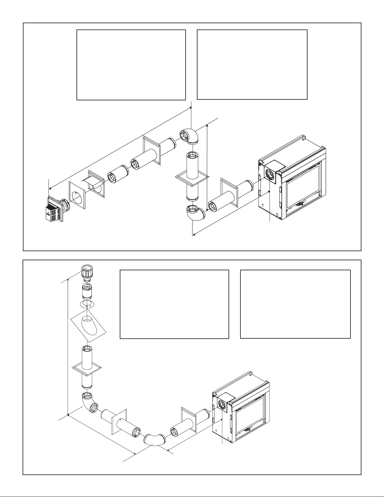
NATURAL GAS
FLUEING WITH TWO 90° ELBOWS
V (FT.) H + H
1
(FT.)
1’ MIN. (305 mm) 3’ MAX. (914 mm)
2’ MIN. (610 mm) 6’ MAX. (1.83 m)
3’ MIN. (914 mm) 9’ MAX. (2.7 m)
4’ MIN. (1.22 m) 12’ MAX. (3.6 m)
5’ MIN. (1.5 m) 15’ MAX. (4.5 m)
V + H + H
= 40’ MAX. (12.2 m)
1
H + H1 = 15’ MAX. (4.5 m)
H
1
PROPANE / BUTANE
FLUEING WITH TWO 90° ELBOWS
V (FT.) H + H
1
(FT.)
1’ MIN. (305 mm) 2’ MAX. (610 mm)
2’ MIN. (610 mm) 4’ MAX. (1.22 m)
3’ MIN. (914 mm) 6’ MAX. (1.83 m)
4’ MIN. (1.22 m) 8’ MAX. (2.4 m)
5’ MIN. (1.5 m) 10’ MAX. (3.0 m)
V + H + H
= 40’ MAX. (12.2 m)
1
= 10’ MAX. (3.0 m)
H + H
1
V
Figure 13. Flueing with Two 90° Elbows
FLUEING WITH TWO 90° ELBOWS
V (FT.) H + H
1’ MIN. (305 mm) 3’ MAX. (914 mm)
2’ MIN. (610 mm) 6’ MAX. (1.83 m)
3’ MIN. (914 mm) 9’ MAX. (2.7 m)
4’ MIN. (1.22 m) 12’ MAX. (3.6 m)
5’ MIN. (1.5 m) 15’ MAX. (4.5 m)
V + H + H
V
NATURAL GAS
= 40’ MAX. (12.2 m)
1
= 15’ MAX. (4.5 m)
H + H
1
1
(FT.)
H
PROPANE / BUTANE
FLUEING WITH TWO 90° ELBOWS
V (FT.) H + H
1’ MIN. (305 mm) 2’ MAX. (610 mm)
2’ MIN. (610 mm) 4’ MAX. (1.22 m)
3’ MIN. (914 mm) 6’ MAX. (1.83 m)
4’ MIN. (1.22 m) 8’ MAX. (2.4 m)
5’ MIN. (1.5 m) 10’ MAX. (3.0 m)
V + H + H1 = 40’ MAX. (12.2 m)
H + H1 = 10’ MAX. (3.0 m)
1
(FT.)
H
1
Figure 14. Flueing with Two 90° Elbows
24
Heat & Glo • PIER/ST/L&RCOR-HVB-CE • 2068-900 Rev. K • 6/09
H
Page 25
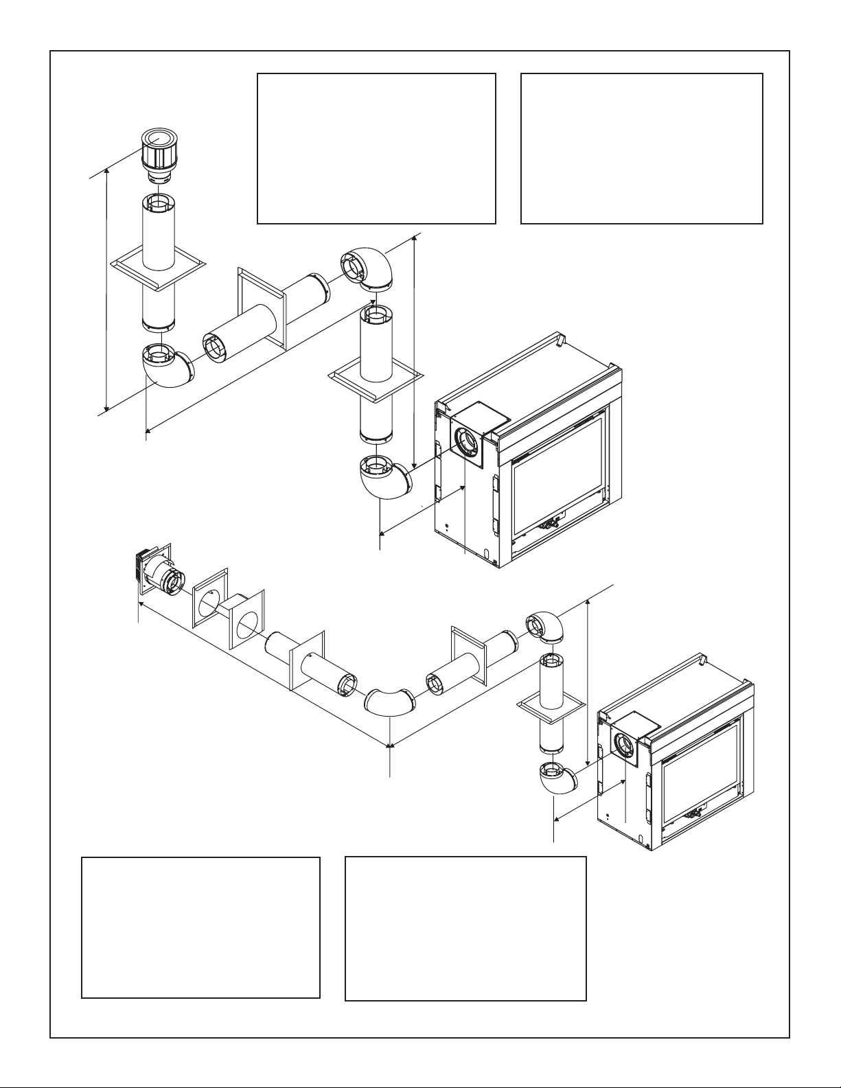
NATURAL GAS
FLUEING WITH THREE 90° ELBOWS
1
V + V
1’ MIN. (305 mm) 3’ MAX. (914 mm)
2’ MIN. (610 mm) 6’ MAX. (1.83 m)
3’ MIN. (914 mm) 9’ MAX. (2.7 m)
4’ MIN. (1.22 m) 12’ MAX. (3.6 m)
5’ MIN. (1.5 m) 15’ MAX. (4.5 m)
V
1
(FT.) H + H1 (FT.)
+ H + H1 = 36’ MAX. (10.9 m)
V+ V
1
H + H1 = 15’ MAX. (4.5 m)
FLUEING WITH THREE 90° ELBOWS
V + V
1’ MIN. (305 mm) 2’ MAX. (610 mm)
2’ MIN. (610 mm) 4’ MAX. (1.22 m)
3’ MIN. (914 mm) 6’ MAX. (1.83 m)
4’ MIN. (1.22 m) 8’ MAX. (2.4 m)
5’ MIN. (1.5 m) 10’ MAX. (3.0 m)
V+ V
PROPANE / BUTANE
1
(FT.) H + H1 (FT.)
+ H + H1 = 36’ MAX. (10.9 m)
1
H + H1 = 10’ MAX. (3.0 m)
V
H
1
H
2
NATURAL GAS
FLUEING WITH THREE 90° ELBOWS
1
V + V
(FT.) H + H1 + H2 (FT.)
1’ MIN. (305 mm) 3’ MAX. (914 mm)
2’ MIN. (610 mm) 6’ MAX. (1.83 m)
3’ MIN. (914 mm) 9’ MAX. (2.7 m)
4’ MIN. (1.22 m) 12’ MAX. (3.6 m)
V+ V1 + H + H1 + H2 = 36’ MAX. (10.9 m)
H + H1 + H2 = 12’ MAX. (3.6 m)
H
H
1
PROPANE / BUTANE
FLUEING WITH THREE 90° ELBOWS
1
V + V
(FT.) H + H1 + H2 (FT.)
1’ MIN. (305 mm) 2’ MAX. (610 mm)
2’ MIN. (610 mm) 4’ MAX. (1.22 m)
3’ MIN. (914 mm) 6’ MAX. (1.83 m)
4’ MIN. (1.22 m) 8’ MAX. (2.4 m)
V+ V1 + H + H1 + H2 = 36’ MAX. (10.9 m)
H + H1 + H2 = 8’ MAX. (2.4 m)
V
H
Figure 15. Flueing with three 90° elbows
Heat & Glo • PIER/ST/L&RCOR-HVB-CE • 2068-900 Rev. K • 6/09 25
Page 26
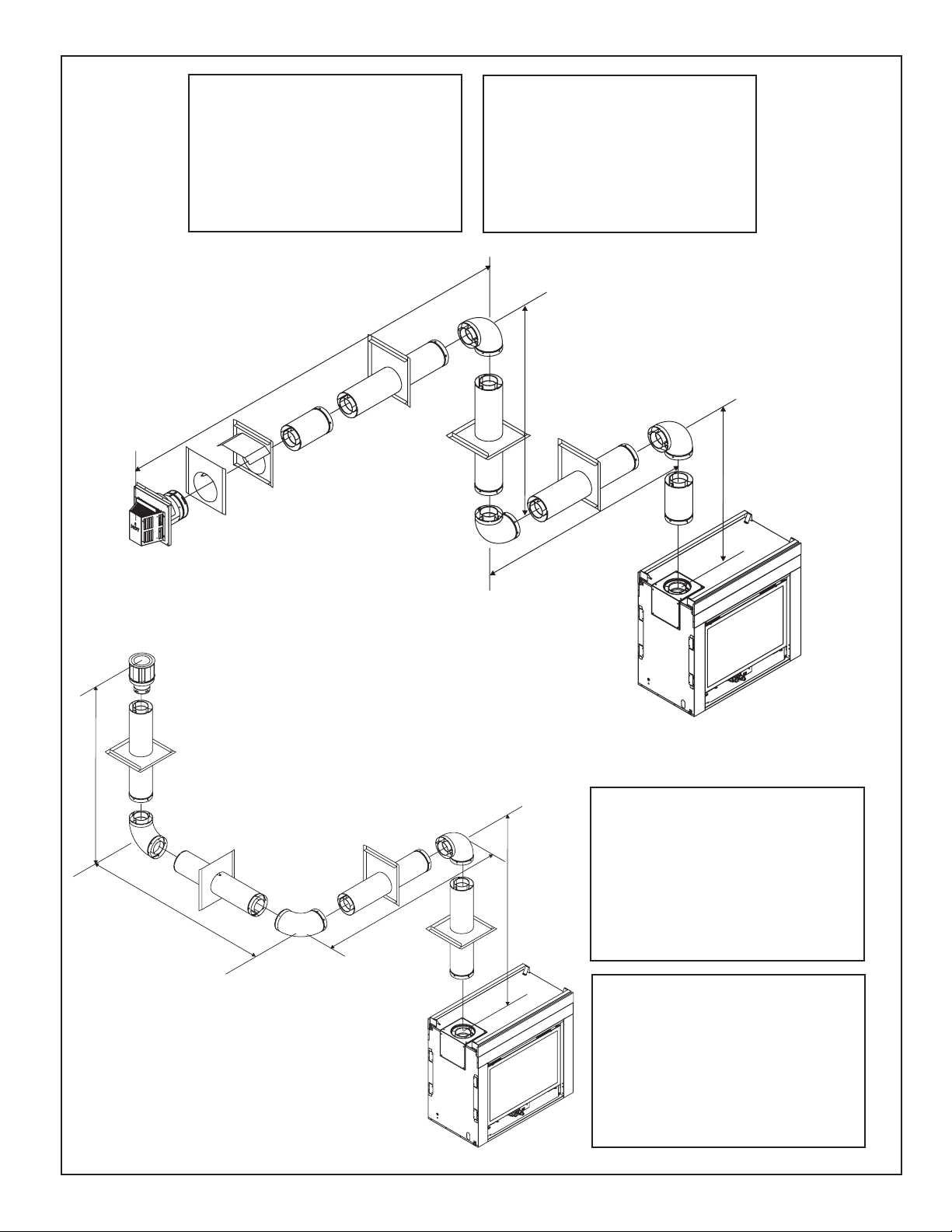
NATURAL GAS
FLUEING WITH THREE 90° ELBOWS
1
V + V
(FT.) H + H1 (FT.)
1’ MIN. (305 mm) 3’ MAX. (914 mm)
2’ MIN. (610 mm) 6’ MAX. (1.83 m)
3’ MIN. (914 mm) 9’ MAX. (2.7 m)
4’ MIN. (1.22 m) 12’ MAX. (3.6 m)
+ H + H1 = 36’ MAX. (10.9 m)
V+ V
1
H + H1 = 12’ MAX. (3.6 m)
H
1
PROPANE / BUTANE
FLUEING WITH THREE 90° ELBOWS
1
V + V
(FT.) H + H1 (FT.)
1’ MIN. (305 mm) 2’ MAX. (610 mm)
2’ MIN. (610 mm) 4’ MAX. (1.22 m)
3’ MIN. (914 mm) 6’ MAX. (1.83 m)
4’ MIN. (1.22 m) 8’ MAX. (2.4 m)
V+ V
+ H + H1 = 36’ MAX. (10.9 m)
1
H + H1 = 8’ MAX. (2.4 m)
V
1
V
H
V
1
H
1
Figure 16. Flueing with three 90° elbows
26
Heat & Glo • PIER/ST/L&RCOR-HVB-CE • 2068-900 Rev. K • 6/09
NATURAL GAS
FLUEING WITH THREE 90° ELBOWS
1
V + V
(FT.) H + H1 (FT.)
1’ MIN. (305 mm) 3’ MAX. (914 mm)
2’ MIN. (610 mm) 6’ MAX. (1.83 m)
3’ MIN. (914 mm) 9’ MAX. (2.7 m)
4’ MIN. (1.22 m) 12’ MAX. (3.6 m)
H
V
5’ MIN. (1.5 m) 15’ MAX. (4.5 m)
V+ V1 + H + H1 = 36’ MAX. (10.9 m)
H + H1 = 15’ MAX. (4.5m)
PROPANE / BUTANE
FLUEING WITH THREE 90° ELBOWS
1
V + V
(FT.) H + H1 (FT.)
1’ MIN. (305 mm) 2’ MAX. (610 mm)
2’ MIN. (610 mm) 4’ MAX. (1.22 m)
3’ MIN. (914 mm) 6’ MAX. (1.83 m)
4’ MIN. (1.22 m) 8’ MAX. (2.4 m)
5’ MIN. (1.5 m) 10’ MAX. (3.0 m)
V+ V1 + H + H1 = 36’ MAX. (10.9 m)
H + H1 = 10’ MAX. (3.0 m)
Page 27
B. Installing Flue Components
After determining which direction the 45
O
elbow will be
used follow fl ueing instructions accordingly.
• This fi replace comes ready to fl ue horizontally. Before
O
attaching additional fl ue pipe, inspect 45
elbow
connection to unit starting collar, if required, snap
in place.
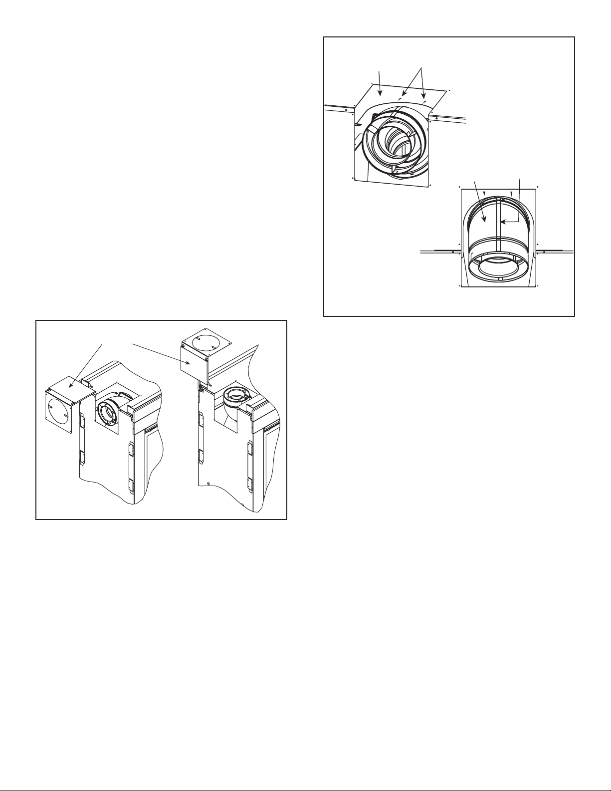
• To fl ue off the unit vertically , the elbow cover plate must
fi rst be removed from the unit (see Figure 17).
• The elbow can be removed from the unit by aligning the
seams of the elbow to the arrows on the surrounding
heat shield (see Figure 18).
• Position the elbow in the vertical position. Snap in place
with the starting collar.
• Replace the elbow cover plate aligning it with the elbow
and secure in place with the 8 screws.
• Place the rope ring around the fi rst section of pipe and
slide it up against the cover plate.
NOTE: The rope ring is needed for the heat manage-
ment and to prevent cold air infi ltration.
HEAT
SHIELD
FRONT VIEW
Figure 18
ARROWS
ELBOW
TOP VIEW
ELBOW
SEAM
ELBOW COVER PLATE
Figure 17
1. Attach the First Flue Component to the Starting
Collars
To attach the fi rst fl ue component to the starting collars
of the fi replace:
• Slide the fi rst fl ue section onto the unit and push in until
they snap lock in position.
• Rotate this section to the desired position.
• Using the two tabs provided on the elbow cover plate,
secure the fi rst section of fl ueing to the fi replace with
two screws.
Refer to Cinch Pipe and Termination Cap installation
instructions.
If the installation is for a termination cap attached directly
to the fi replace, skip to the sections, Install Firestops and
Flue Termination.
Heat & Glo • PIER/ST/L&RCOR-HVB-CE • 2068-900 Rev. K • 6/09 27
Page 28
2. Continue Adding Flue Components
Refer to Cinch Pipe and Termination Cap installation instructions.
• Continue adding fl ue components, locking each succeed-
ing component into place.
• Ensure that each succeeding fl ue component is securely
fi tted and locked into the preceding component in the fl ue
system. Securing pipe sections with a maximum of two
screws is recommended.
• 90° elbows may be installed and rotated to any point
around the preceding component’s vertical axis. If an
elbow does not end up in a locked position with the
preceding component, attach with a minimum of two (2)
sheet metal screws.
3. Install Support Brackets
Refer to Cinch Pipe and Termination Cap installation instructions.
4. Install Firestops
For Horizontal Runs - Firestops are REQUIRED on
both sides of a combustible wall through which the fl ue
passes.
NOTE: Model DVP-TRAP does not need an exterior
fi restop on an exterior combustible wall. The fi restop
is built into the cap.
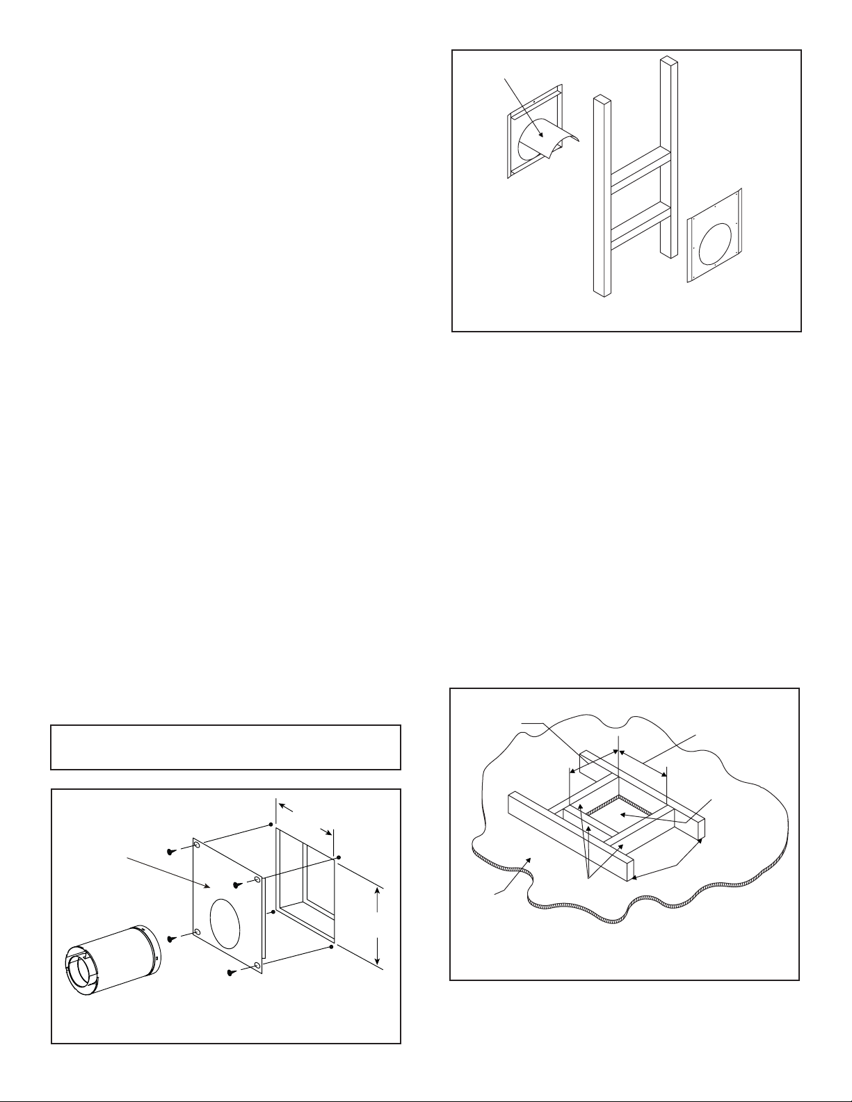
To install fi restops for horizontal runs that pass through
either interior or exterior walls:
• Cut a 10” x 12” (254 mm X 305 mm) hole through the
wall.
NOTE: The center of the hole is one (1) inch (25.4mm)
above the center of the horizontal fl ue pipe.
• Position the fi restops on both sides of the hole previously
cut and secure the fi restops with nails or screws.
• The heat shields of the fi restops MUST BE placed to-
wards the top of the hole.
• Continue the fl ue run through the fi restops.
NOTE: There must be NO INSULATION or other
combustibles inside the framed fi restop opening.
HEAT SHIELD
INTERIOR
FIRESTOP
TRIM HEAT
SHIELD IF TOO
LONG, ADD TO
SHIELD IF TOO
SHORT
EXTERIOR
FIRESTOP
Figure 20. Heat Shield, Interior & Exterior Firestops
For Vertical Runs - One ceiling fi restop is REQUIRED at
the hole in each ceiling through which the fl ue passes.
To install fi restops for vertical runs that pass through
ceilings:
• Position a plumb bob directly over the center of the vertical fl ue component.
• Mark the ceiling to establish the centerpoint of the fl ue.
• Drill a hole or drive a nail through this centerpoint.
• Check the fl oor above for any obstructions, such as wir-
ing or plumbing runs.
• Reposition the fi replace and fl ue system, if necessary,
to accommodate the ceiling joists and/or obstructions.
• Cut an 10-inch X 10-inch (254mm x 254mm) hole through
the ceiling, using the centerpoint previously marked.
• Frame the hole with framing lumber the same size as
the ceiling joists.
10" (254 mm)
10” (254 mm)
INTERIOR
WALL SHIELD
Figure 19. 10” x 12” Hole and Flue Pipe
28
Heat & Glo • PIER/ST/L&RCOR-HVB-CE • 2068-900 Rev. K • 6/09
10"
254 mm
12"
305 mm
CHIMNEY
HOLE
EXISTING CEILING
JOISTS
CEILING
NEW
FRAMING
MEMBERS
Figure 21. Hole & New Framing Members
Page 29
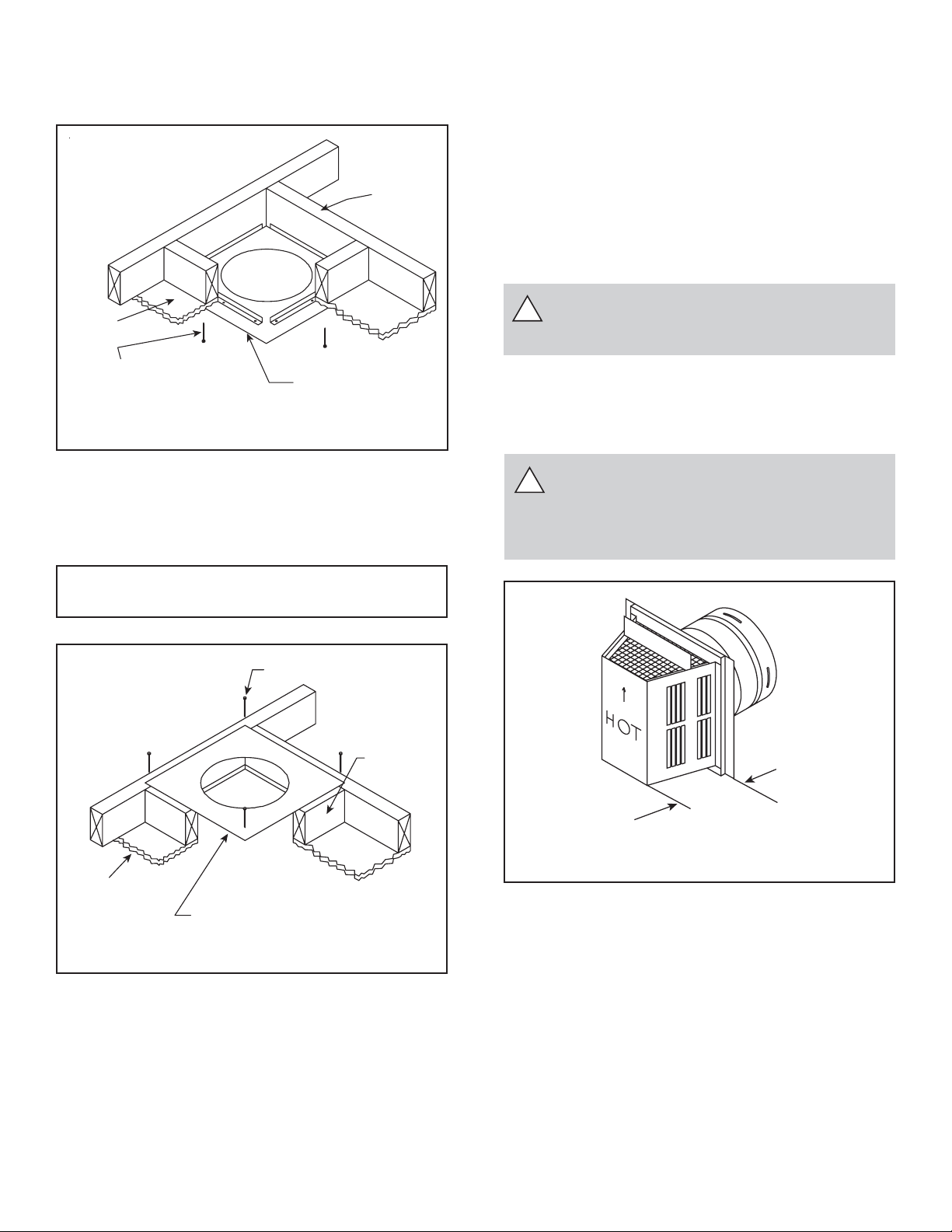
If the area above the ceiling is NOT an attic, position
and secure the ceiling fi restop on the ceiling side of the
previously cut and framed hole.
JOIST
CEILING
C. Flue Termination
For Horizontal Terminations - To attach and secure the
termination to the last section of horizontal fl ue refer to the
Cinch Pipe and Termination Cap installation instructions.
• Push on and snap lock as described at the beginning of
the Installing Flue Components section.
• The termination kit should pass through the wall fi restops
from the exterior of the building.
• Adjust the termination cap to its fi nal exterior position on
the building and interlock the fl ue sections.
WARNING: THE TERMINATION CAP MUST
!
BE POSITIONED SO THAT THE ARROW IS
POINTING UP.
NAILS (4 REQUIRED)
CEILING FIRESTOP
Figure 22. Ceiling Firestop (Ceiling Side)
If the area above the ceiling IS an attic, position and secure
the fi restop on top of the previously framed hole.
NOTE: Keep insulation away from the fl ue pipe at least
25 mm.
NOTE: There must be NO INSULATION or other
combustibles inside the framed fi restop opening.
NAILS (4 REQUIRED)
RAFTER
For trapezoidal cap termination kits:
• Using screws secure the cap to the exterior wall through
the fl anges in the cap.
WARNING: FLUEING TERMINALS SHALL
!
NOT BE RECESSED INTO A WALL OR SIDING. FLUE TERMINATION CLEARANCES
MUST BE FOLLOWED TO AVOID FIRE
DANGER.
(184 mm)
CEILING
CEILING FIRESTOP
Figure 23. Attic Firestop
Figure 24. Trapezoid Termination Cap
Heat & Glo • PIER/ST/L&RCOR-HVB-CE • 2068-900 Rev. K • 6/09 29
Page 30
For Vertical Terminations - To locate the fl ue and install
V
the fl ue sections:
• Locate and mark the fl ue centerpoint on the underside
of the roof, and drive a nail through the centerpoint.
• Make the outline of the roof hole around the centerpoint
nail.
• The size of the roof hole framing dimensions depend on the
pitch of the roof. There MUST BE a 25.4mm clearance
from the vertical fl ue pipe to combustible materials.
• Mark the roof hole accordingly.
• Cover the opening of the installed fl ue pipes.
• Cut and frame the roof hole.
• Use framing lumber the same size as the roof rafters
and install the frame securely . Flashing anchored to the
frame must withstand heavy winds.
• Continue to install concentric fl ue sections up through
the roof hole (for inside fl ue installations) or up past the
roof line until you reach the appropriate distance above
the roof (for outside terminations).
To seal the roof hole, and to divert rain and snow from the
fl ue system:
• Attach a fl ashing to the roof using nails, and use a non-
hardening mastic around the edges of the fl ashing base
where it meets the roof.
• Attach a storm collar over the fl ashing joint to form a
water-tight seal. Place non-hardening mastic around the
joint, between the storm collar and the vertical pipe.
• Slide the termination cap over the end of the fl ue pipe
and snap into place.
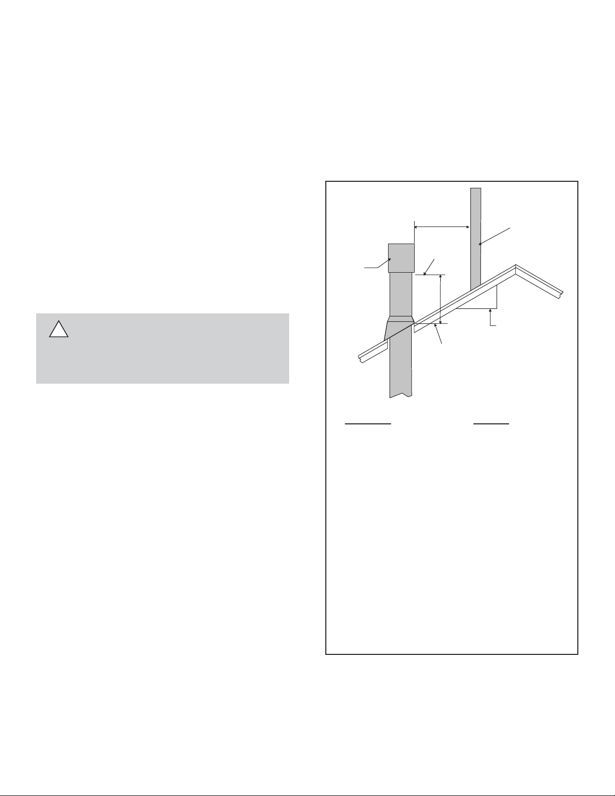
TERMINATION
CAP
50.8 cm
LOWEST
DISCHARGE
OPENING
30.5 cm
X
ERTICAL
WALL
WARNING: FOLLOWING NATIONAL
!
REGULATIONS AND CODES OF PRACTICE
FOR MINIMUM CLEARANCES FROM GAS
TERMINALS, AND PLACEMENT OF GAS
TERMINAL.
NOTE: This also pertains to vertical fl ue systems in-
stalled on the outside of the building.
ROOF PITCH
IS X/ 30.5 cm
H (MIN.) - MINIMUM HEIGHT FROM ROOF
TO LOWEST DISCHARGE OPENING
Roof Pitch H (min.)
fl at to 6/12 305 mm (1.0 ft.)*
6/12 to 7/12 381 mm (1.25 ft.)*
over 7/12 to 8/12 458 mm (1.5 ft.)*
over 8/12 to 9/12 610 mm (2.0 ft.)*
over 9/12 to 10/12 762 mm (2.5 ft.)*
over 10/12 to 11/12 991 mm (3.25 ft.)
over 11/12 to 12/12 1.2 m (4.0 ft.)
over 12/12 to 14/12 1.5 m (5.0 ft.)
over 14/12 to 16/12 1.9 m (6.0 ft.)
over 16/12 to 18/12 2.2 m (7.0 ft.)
over 18/12 to 20/12 2.3 m (7.5 ft.)
over 20/12 to 21/12 2.5 m (8.0 ft.)
* 91.4 cm minimum in snow regions
Figure 25. Minimum Height from Roof to
Lowest Discharge Opening
30
Heat & Glo • PIER/ST/L&RCOR-HVB-CE • 2068-900 Rev. K • 6/09
Page 31
R
M
N
P
Q
(See Note 2)
= VENT TERMINAL
V
X
= AIR SUPPLY INLET
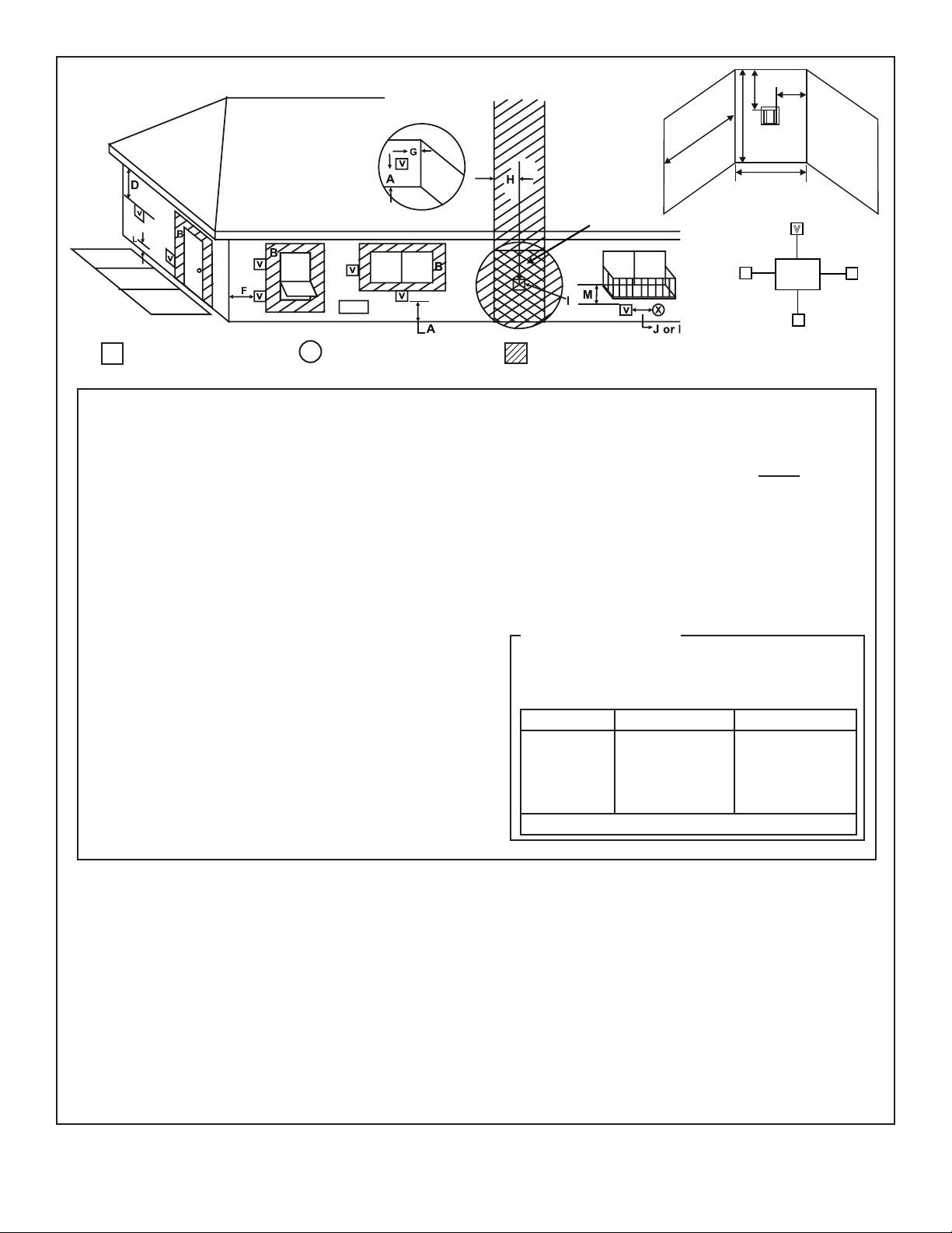
A = 30.5 cm .................clearances above grade, veranda,
(See Note 1)
porch, deck or balcony
B = 30.5 cm .................clearances to window or door
that may be opened, or to permanently closed window. (Glass)
D* = 50.8 cm .................vertical clearance to unventilated
soffi t or to ventilated soffi t located
above the terminal
84.8 cm ..................for vinyl clad soffi ts and below
electrical service
F = 22.9 cm ................clearance to outside corner
G = 15.3 cm .................clearance to inside corner
H = 91.4 cm .................not to be installed above a gas
meter/regulator assembly within
91.4 cm horizontally from the
center-line of the regulator
I = 91.4 m ...................clearance to gas service regulator
fl ue outlet
J = 22.9 cm ...................clearance to non-mechanical
air supply inlet to building or the
combustion air inlet to any other
appliance
See Notes 3 & 4
V
V
T
Electrical
Service
V
S
V
D*
S
= AREA WHERE TERMINAL IS NOT PERMITTED
K = 91.4 m .....................clearance to a mechanical
(powered) air supply inlet
L = 2.1 m .......................clearance above paved
(See Note 1)
sidewalk or a paved driveway
located on public property
M* = 50.8 cm ...................clearance under veranda, porch,
deck, balcony or overhang
118.9 m ..................vinyl
S = 15.3 cm ....................clearance from sides of elec-
(See Note 5)
trical service
T = 30.5 cm .....................clearance above electrical
(See Note 5)
service
Alcove Applications
N = 15.3 cm ..................non-vinyl sidewalls
30.5 cm ..................vinyl sidewalls
P = 2.4 m
1 cap .91 m 2 x Q
2 caps 1.8 m 1 x Q
3 caps 2.7 m 2/3 x Q
4 caps 3.7 m 1/2 x Q
Q
= # termination caps x 3 R
MIN
Q
MIN
= (2 / # termination caps) x Q
MAX
R
MAX
ACTUAL
ACTUAL
ACTUAL
ACTUAL
ACTUAL
* only permitted if veranda, porch, deck or balcony is fully open on a
minimum of 2 sides beneath the fl oor, or meets Note 2.
NOTE 3: Local codes or regulations may require different
clearances.
NOTE 1: On private property where termination is less than 2.1 M above
a sidewalk, driveway, deck, porch, veranda or balcony, use of a listed cap
shield is suggested. (See vents components page)
NOTE 2: Termination in an alcove space (spaces open only on one side
and with an overhang) are permitted with the dimensions specifi ed for
vinyl or non-vinyl siding and soffi ts. 1. There must be 91.4 cm minimum
between termination caps. 2. All mechanical air intakes within 3.0 M of
a termination cap must be a minimum of 91.4 cm below the termination
cap. 3. All gravity air intakes within 91.4 cm of a termination cap must be
a minimum of 30.5 cm below the termination cap.
NOTE 6: Vent system termination is permitted in porch areas with
two or more sides open. You must follow all side walls, overhang
and ground clearances as stated in the instructions.
NOTE 7: For terminals adjacent to walkways, terminal guards in
accordance with BS EN 483:2001 are strongly recommended.
Heat & Glo assumes no responsibility for the improper performance
of the appliance when the venting system does not meet these
requirements.
Figure 26. Vent Termination Minimum Clearances
CAUTION: IF EXTERIOR WALLS ARE FINISHED WITH VINYL SIDING, IT IS SUGGESTED THAT A VINYL PROTECTOR KIT
BE INSTALLED.
Heat & Glo • PIER/ST/L&RCOR-HVB-CE • 2068-900 Rev. K • 6/09 31
Page 32
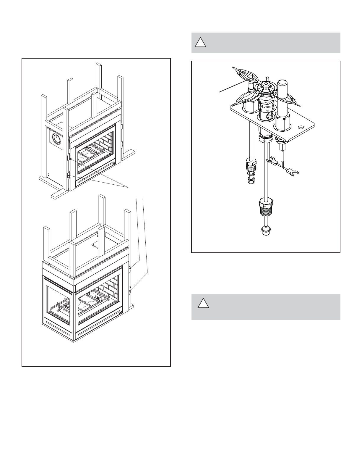
Step 4. Positioning, Leveling, and Securing
the Fireplace
The diagram below shows how to properly position, level,
and secure the fi replace.
NAILING TABS
(BOTH SIDES)
Step 5. The Gas Control System
WARNING: THIS UNIT IS NOT FOR USE WITH
!
SOLID FUEL.
Standing Pilot
Flame Sensor Rod
Figure 27. Proper Positioning, Leveling, and
Securing of a Fireplace
• Place the fi replace into position.
• Level the fi replace from side to side and from front to
back.
• Shim the fi replace with non-combustible material, such
as sheet metal, as necessary.
• Secure the fi replace to the framing by nailing or screw-
ing.
• Holes are provided in the base pan for securing the unit
to the fl oor .
Figure 28. Gas Control System
Standing Pilot Ignition System
This system includes millivolt control valve, Standing Pilot,
thermopile/thermocouple fl ame sensor, and piezo ignitor.
WARNING: 230 VAC MUST NEVER BE CON-
!
NECTED TO A CONTROL VALVE IN A MILLIVOLT SYSTEM.
32
Heat & Glo • PIER/ST/L&RCOR-HVB-CE • 2068-900 Rev. K • 6/09
Page 33
Step 6. The Gas Supply Line
NOTE: Have the gas supply line installed in accordance
with local building codes by a qualified installer
approved and/or licensed as required by the locality.
NOTE: Before the fi rst fi ring of the fi replace, the gas
supply line should be purged of any trapped air.
NOTE: Consult local building regulations to properly
size the gas supply line leading to the (Rp 1/2 in.)
hook-up at the unit.
This threaded gas inlet connection is ISO 7-Rp 1/2 (BSP
Rp 1/2).
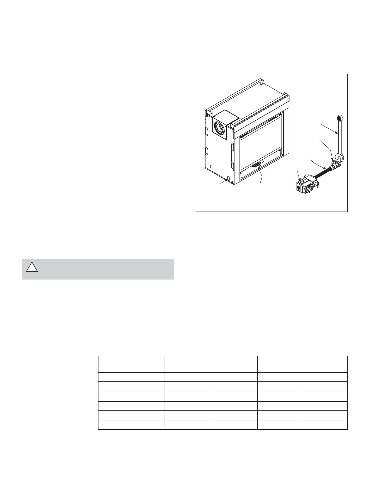
To install the gas supply line:
• Locate the gas line access hole in the outer casing of
the fi replace.
• The gas line may be run from either side of the fi replace
provided the hole in the outer wrap does not exceed 51mm
(2 in.) in diameter and it does not penetrate the actual
fi rebox.
• Open the fi replace lower grille, insert the gas supply line
through the gas line hole, and connect it to the shut-off
valve.
• When attaching the pipe, support the control so that the
lines are not bent or torn.
• After the gas line installation is complete, all connections must be tightened and checked for leaks with a
commercially-available, non-corrosive leak check solution. Be sure to rinse off all leak check solution following
testing.
WARNING: DO NOT USE AN OPEN FLAME TO
!
CHECK FOR GAS LEAKS.
• Insert insulation from the outside of the fi replace and pack
the insulation tightly to totally seal between the pipe and
the outer casing.
• At the gas line access hole the gap between the supply
piping and gas access hole can be plugged with noncombustible insulation to prevent cold air infi ltration.
USE A WRENCH ON
SHUT-OFF VALVE
WHEN TIGHTENING
GAS LINE.
MANUAL
SHUT-OFF
VALVE
FLEX CONNECTOR
GAS VALVE
GAS LINE
ACCESS
CONTROL VALVE
Figure 29. Gas Supply Line
Step 7. Gas Pressure Requirements
Pressure requirements for Heat & Glo gas fi replaces are
shown in Table 1 below.
A tap is provided on the outlet side of the gas control for a
test gauge connection to measure the manifold pressure.
To measure inlet pressure, provisions must be made to
attach a test gauge to the tap immediately upstream of
the gas supply connection to the fi replace.
The fi replace and its individual shut-off valve must be
disconnected from the gas supply piping system during
any pressure testing of the system at test pressures in
excess of 60 mbar.
If the fi replace must be isolated from the gas supply piping
system by closing an individual shut-off valve, it must be
of the handle-less type.
Table 1
Natural Gas
(G20)
Propane
(G31)
Butane
(G30)
Natural Gas
(G25)
Inlet Pressure 20 mbar 37 o 50 mbar 30 o 50 mbar 25 mbar
Manifold Pressure 4-8,7 mbar 15,7-25 mbar 15,7-25 mbar 4-8,7 mbar
Gas Rate
Max.Input(NETCV)
/
,54
h
9,6 kW 9,9 kW 7,9 kW 7,8 kW
,24 m3/
h
.16 m3/
h
.54 m3/
h
m3
Burner Injector DMS 33 DMS 51 DMS 53 DMS 33
Pilot Injector 51 30 30 51
Heat & Glo • PIER/ST/L&RCOR-HVB-CE • 2068-900 Rev. K • 6/09 33
Page 34
Step 8. Wiring the Fireplace
NOTE: Electrical wiring must be installed by a licensed electrician.
For Standing Pilot Ignition Wiring
Appliance Requirements
WARNING: DO NOT CONNECT
!
230 VAC TO THE GAS CONTROL
VALVE OR THE APPLIANCE WILL
MALFUNCTION AND THE VALVE
WILL BE DESTROYED.
Optional Accessories
Optional remote control kits require that 230 V AC be wired to the factory
installed junction box before the fi replace is permanently installed.
Wall Switch
Position the wall switch in the desired position on a wall. Run a
maximum of 780cm or less length of 0.102 cm diameter minimum wire
and connect it to the fi replace ON/OFF switch pigtails.
Step 9. Finishing
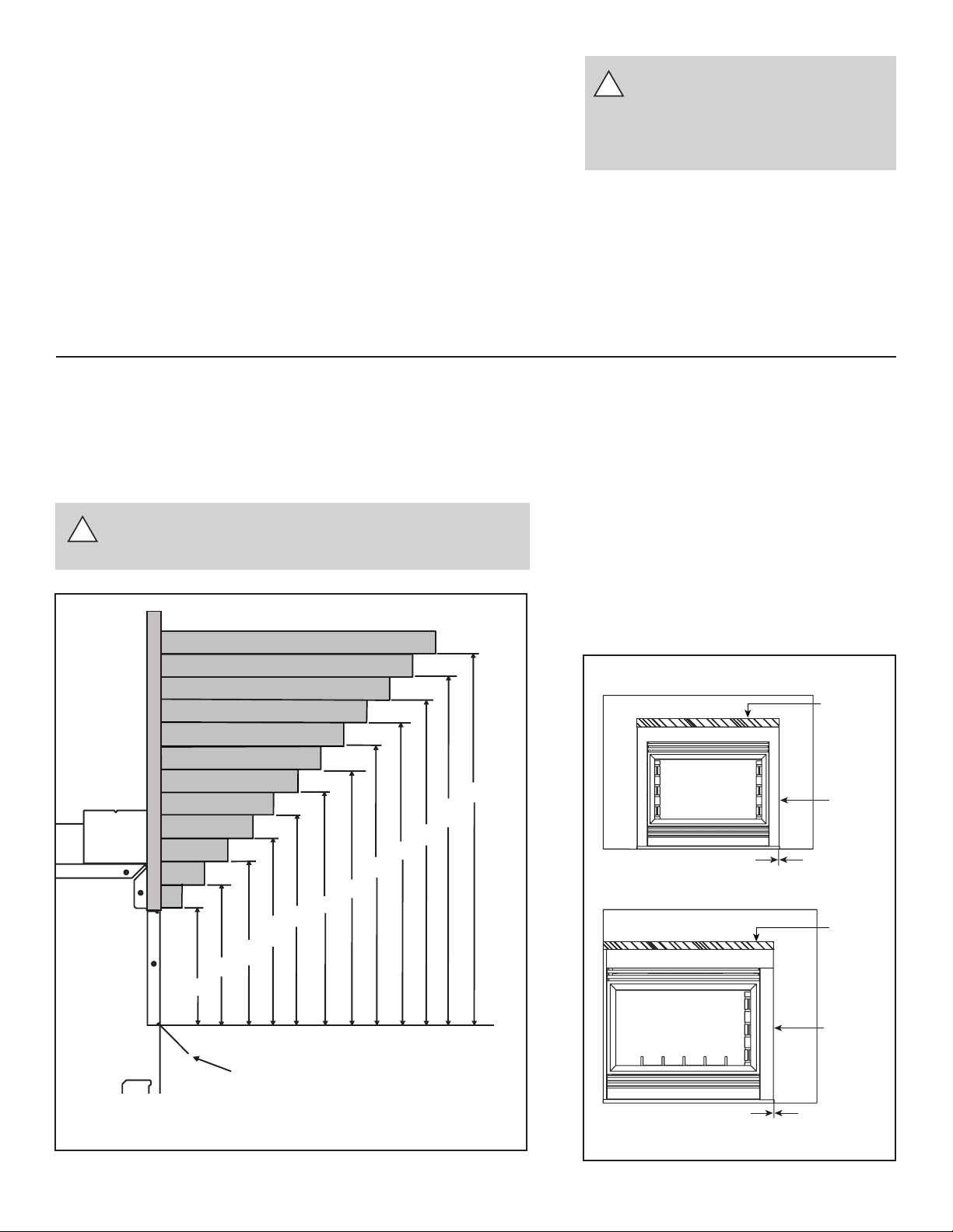
Figure 30 shows the minimum vertical and corresponding maximum
horizontal dimensions of fi replace mantels or other combustible
projections above the top front edge of the fi replace. See Figures 4
and 5 for other fi replace clearances. Only non-combustible materials
may be used to cover the black fi replace front.
WARNING: WHEN FINISHING THE FIREPLACE, NEVER
!
OBSTRUCT OR MODIFY THE AIR INLET/OUTLET
GRILLES IN ANY MANNER.
305 mm
280 mm
254 mm
407 mm
381 mm
356 mm
331 mm
305 mm
280 mm
77 mm
51 mm
25.4 mm
127 mm
102 mm
153 mm
127 mm
178 mm
MANTEL
153 mm
204 mm
178 mm
229 mm
228 mm
204 mm
254 mm
CAUTION: LABEL ALL WIRES PRIOR TO
DISCONNECTION WHEN SERVICING CONTROLS. WIRING ERRORS CAN CAUSE
IMPROPER AND DANGEROUS OPERATION. VERIFY PROPER OPERATION AFTER
SERVICING.
CAUTION: IF JOINTS BETWEEN THE FINISHED WALLS AND THE FIREPLACE SURROUND (TOP AND SIDES) ARE SEALED,
A 150º C. MINIMUM SEALANT MATERIAL
MUST BE USED. THESE JOINTS ARE NOT
REQUIRED TO BE SEALED. ONLY NONCOMBUSTIBLE MA TERIAL (USING 150° C.
MINIMUM ADHESIVE, IF NEEDED) CAN BE
APPLIED AS FACING TO THE FIREPLACE
SURROUND (SEE FIGURE 31).
NOTE: Sheetrock or other combustible
material such as wood can be placed on
the top edge and sides of the fi replace.
ST-HVB-CE
TOP
EDGE
SIDE
EDGE
0 mm GAG
PIER-HVB-CE and L/RCOR-HVB-CE
TOP
EDGE
NOTE: 305 mm (12 in.) mantel at
HOOD
407 mm (16 in.) above hood.
Figure 30. Minimum Vertical and Maximum Horizontal
Dimensions of Combustibles above Fireplace
34
Heat & Glo • PIER/ST/L&RCOR-HVB-CE • 2068-900 Rev. K • 6/09
SIDE
EDGE
0 mm GAG
Figure 31. Sealant Material
Page 35
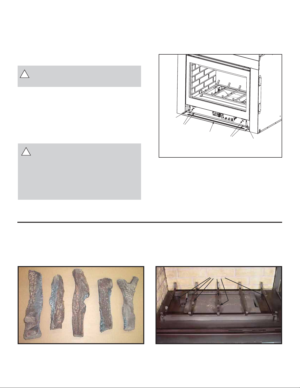
Step 10. Installing Trim, Logs & Ember Material
Installing the Trim
Combustible materials may be brought up to the specifi ed
clearances on the side and top front edges of the fi replace,
but MUST NEVER overlap onto the front face. The joints
between the fi nished wall and the fi replace top and sides
can only be sealed with a 149° C minimum sealant.
WARNING: WHEN FINISHING THE FIREPLACE,
!
NEVER OBSTRUCT OR MODIFY THE AIR INLET/OUTLET GRILLES IN ANY MANNER.
Install optional marble and brass trim surround kits
as desired. Marble, brass, brick, tile, or other noncombustible materials can be used to cover up the gap
between combustible material (sheetrock or wood) and
the fi replace.
Do not obstruct or modify the air inlet/outlet grilles. When
overlapping on both sides, leave enough space so that the
bottom grille can be lowered and the trim door removed.
WARNING: CHILDREN AND ADULTS
!
SHOULD BE ALERTED TO THE HAZARDS
OF HIGH TEMPERATURES OF WORKING
SURFACES ON THESE FIREPLACES.
WORKING SURFACES INCLUDE ALL
GLASS P ANELS AND DECORA TIVE DOORS.
YOUNG CHILDREN SHOULD BE CAREFULL Y
SUPERVISED WHEN THEY ARE IN THE SAME
ROOM AS THE APPLIANCE.
Attachment of Lower Door Assembly
This unit is shipped with the door stops unattached to
assist in the set-up of the unit. After the gas and electrical
have been run, the door stops can be used if desired as
shown in Figure 32.
DOOR
STOPS
SHOULDER
BOLT
Figure 32. Lower Door Assembly
LOWER
DOOR
SHOULDER
BOLT
DOOR
STOPS
Log placement
Log Set Assembly: LOGS-ST-CE
Only for Models: ST-HVB-CE, PIER-HVB-CE and RCOR-HVB-CE
TABS
4
1
2
3
6
5
CAUTION: Logs are fragile. Carefully remove the logs from the packaging. Logs #4 and #5 are the same log.
See Service Parts pages for individual assembly photos.
Heat & Glo • PIER/ST/L&RCOR-HVB-CE • 2068-900 Rev. K • 6/09 35
Page 36
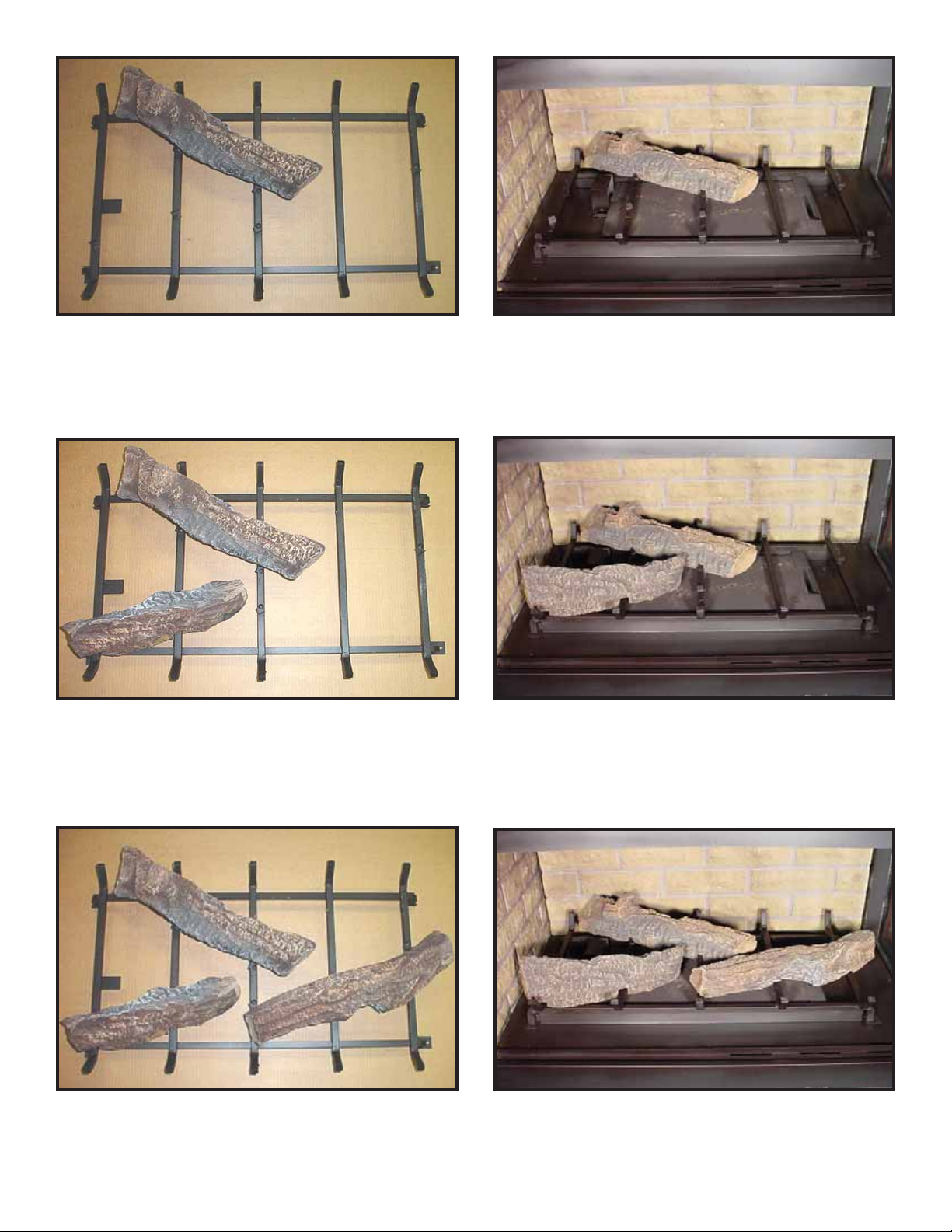
1
LOG #1 (SRV2068-700): Place log #1 behind grate tabs on the second and third grate bars on the left rear corner .
Position so that the bottom grooves fi t over bars and the log is snug against the grate tabs.
2
LOG #2 (SRV2068-701): Locate log #2 in left front corner of the log grate using bottom grooves for placement.
Push log against grate tabs on fi rst and second bars.
3
LOG #3 (SRV2068-702): Position log #3 across the third, fourth and fi fth grate bars and push towards the rear
against the grate tabs on bars three and fi ve.
36
Heat & Glo • PIER/ST/L&RCOR-HVB-CE • 2068-900 Rev. K • 6/09
Page 37
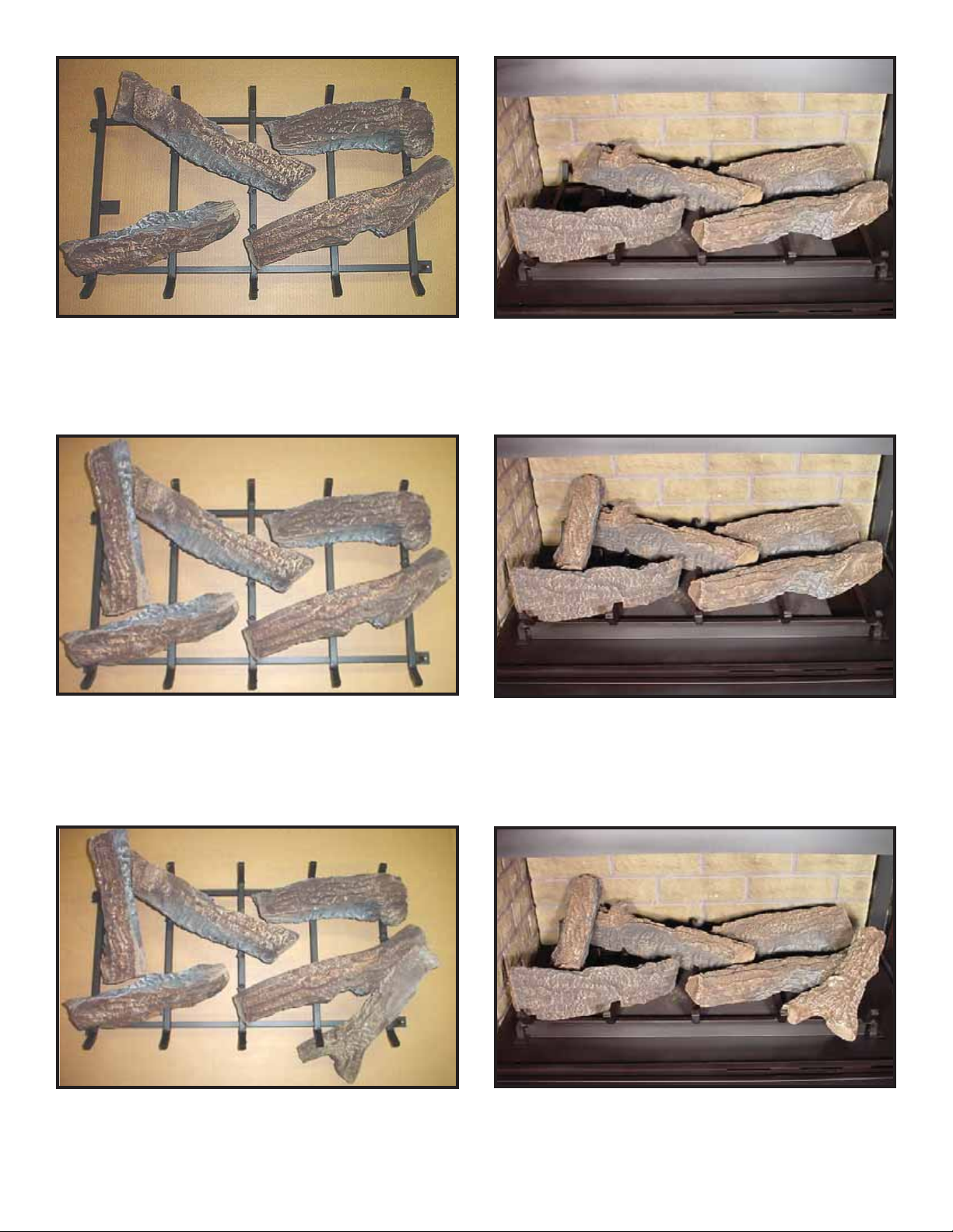
4
LOG #4 (SRV2068-703): Place log #4 in the right rear corner of the log grate using bottom grooves for placement.
Align log #4 by using the grate corner and rear cross bar as stops.
5
LOG #5 (SRV2068-703): Place log #5 on top of fl at spot on log #1 and against the inside of log #2. Be careful
not to reposition log #2 when placing this log.
6
LOG #6 (SRV582-705): Position log #6 on top of the groove in log #3 with the forked end resting on the grate
assembly as shown.
Heat & Glo • PIER/ST/L&RCOR-HVB-CE • 2068-900 Rev. K • 6/09 37
Page 38
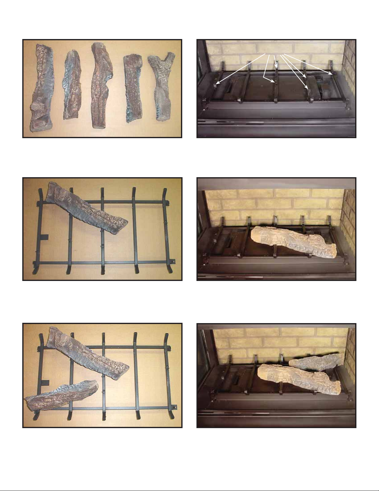
Only for Model: LCOR-HVB-CE
TABS
4
1
2
3
6
5
CAUTION: Logs are fragile. Carefully remove the logs from the packaging. Logs #4 and #5 are the same log.
See Service Parts pages for individual assembly photos.
1
LOG #1 (SRV2068-700): Place log #1 in front of grate tabs on the third and fourth grate bars on the right front
corner. Position so that the bottom grooves fi t over bars and the log is snug against the grate tabs.
2
LOG #2 (SRV2068-701): Locate log #2 in right rear corner of the log grate using bottom grooves for placement.
Place log against grate tabs on fourth and fi fth bars.
38
Heat & Glo • PIER/ST/L&RCOR-HVB-CE • 2068-900 Rev. K • 6/09
Page 39
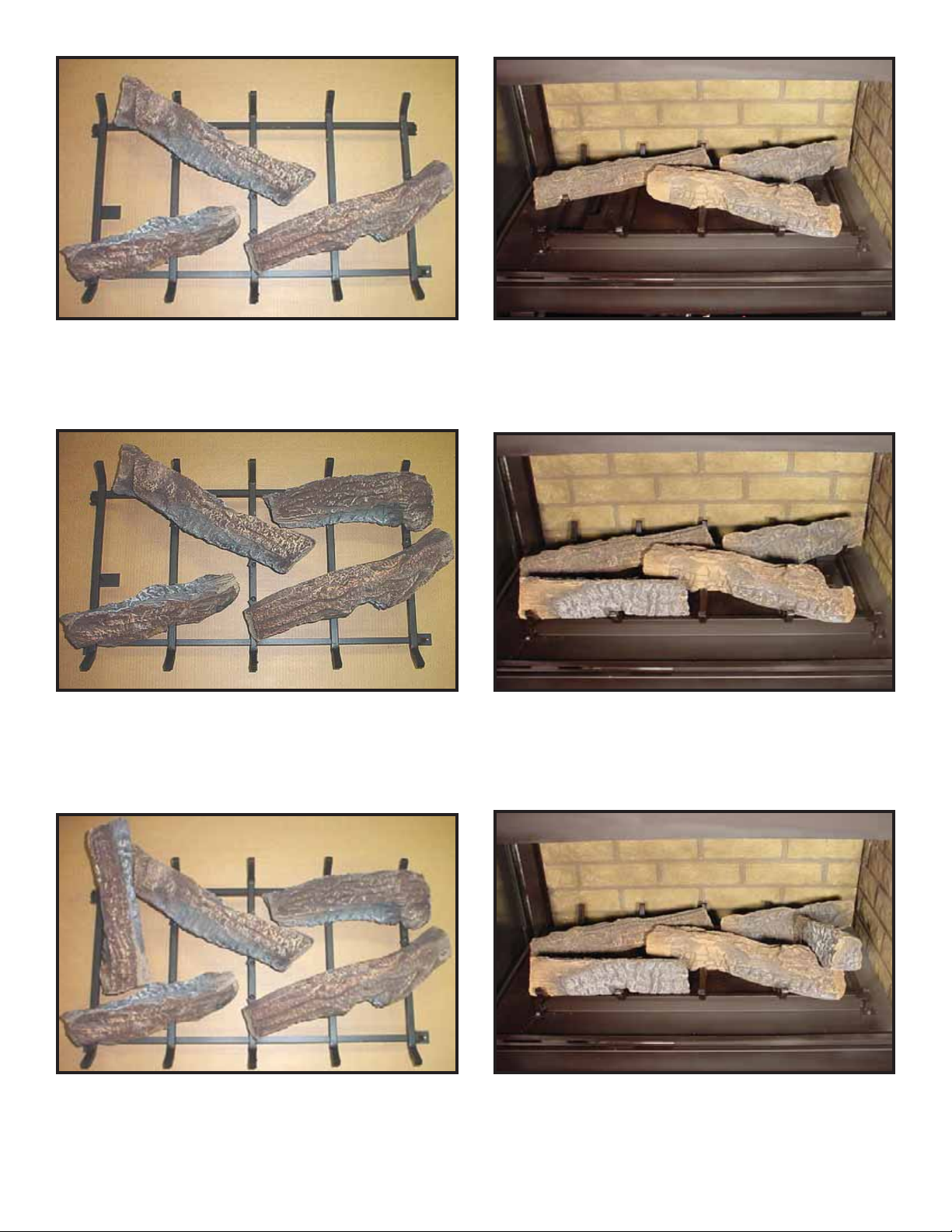
3
LOG #3 (SRV2068-702): Position log #3 across the fi rst, second and third grate bars and pull towards the front
against the grate tabs on bars one and three.
4
LOG #4 (SRV2068-703): Place log #4 in the left front corner of the log grate using bottom grooves for placement.
Align log #4 by using the grate corner and front cross bar as stops.
5
LOG #5 (SRV2068-703): Place log #5 on top of fl at spot on log #1 and against the inside of log #2. Be careful
not to reposition log #2 when placing this log.
Heat & Glo • PIER/ST/L&RCOR-HVB-CE • 2068-900 Rev. K • 6/09 39
Page 40
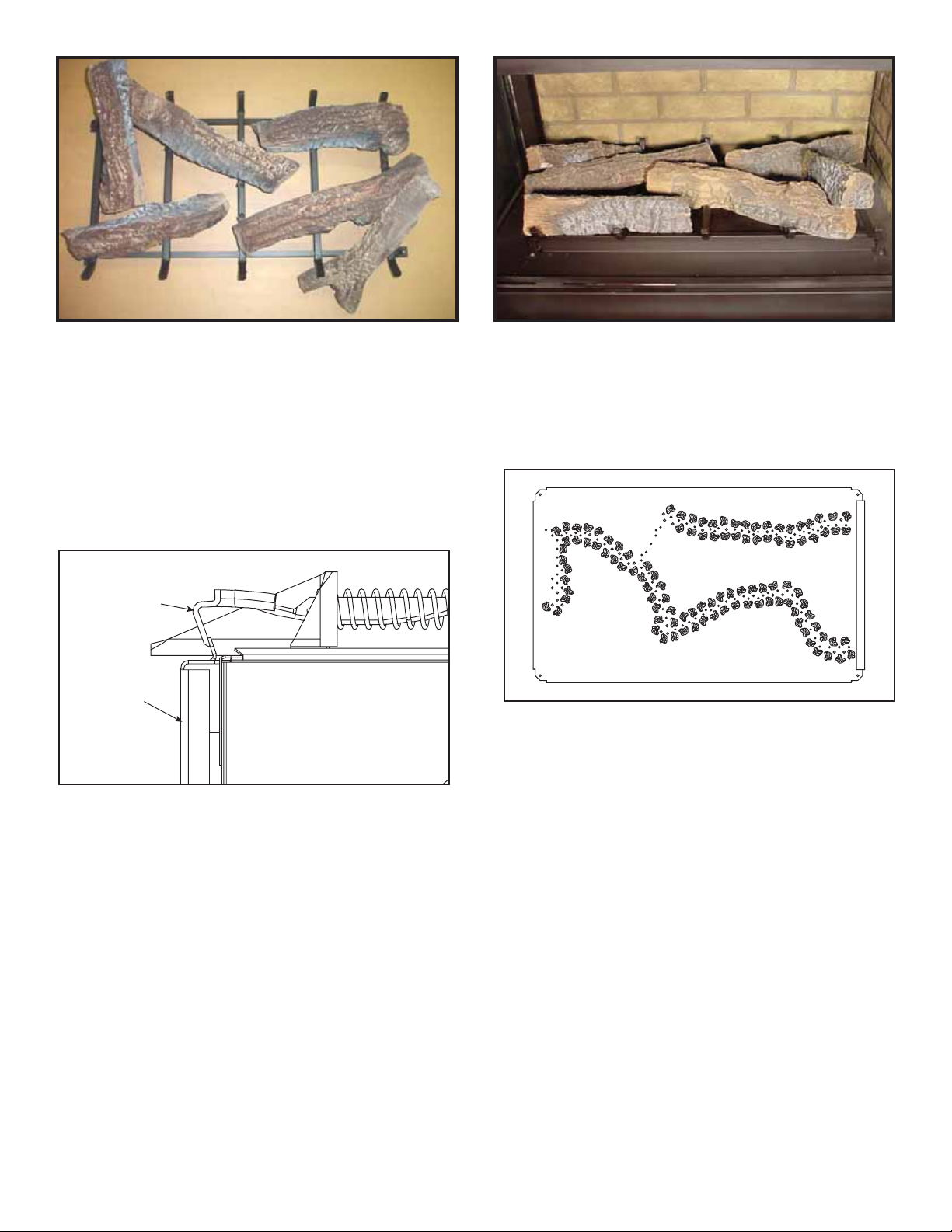
6
LOG #6 (SRV582-705): Position log #6 on top of the groove in log #3 with the forked end resting on the grate
assembly as shown.
Placing the Ember Material
Ember material is shipped with this gas fi replace. To place
the ember material:
LATCHES
(BOTH TOP
AND BOTTOM)
GLASS
ASSEMBLY
Figure 34. Placement of Embers
Figure 33.
• Remove the tension springs around the glass door.
• Remove the glass door from the unit.
• Remove the log set.
• Place dime size pieces of ember material about 1/2
inch apart near port holes in burner top. Do NOT place
embers over burner ports. Cover the top of the burner
with a single layer of ember material.
• Save the remaining ember materials for use during fi re-
place servicing. The bag of embers provided is suffi cient
for 3 to 5 applications.
• Install the Lava Rock (supplied) to the fi rebox base
pan being careful not to cover the burner with the Lava
Rock.
• Replace the logs, glass door, and a front trim door on
the unit.
40
Heat & Glo • PIER/ST/L&RCOR-HVB-CE • 2068-900 Rev. K • 6/09
Page 41
Step 11. Before Lighting the Fireplace
WARNING
HOT SURFACES!
Glass and other surfaces are hot during
operation AND cool down.
Hot glass will cause burns.
• DO NOT touch glass until it is cooled
• NEVER allow children to touch glass
• Keep children away
• CAREFULLY SUPERVISE children in same room as
fi replace.
• Alert children and adults to hazards of high temperatures.
High temperatures may ignite clothing or other fl ammable
materials.
• Keep clothing, furniture, draperies and other fl ammable
materials away.
This appliance has been supplied with an integral barrier
to prevent direct contact with the fi xed glass panel. DO
NOT operate the appliance with the barrier removed.
Before lighting the fi replace, be sure to do the following:
Remove all paperwork from underneath the fi replace.
Review safety warnings and cautions
• Read the Safety and Warning Information section at
the beginning of this Installers Guide.
Double-check for gas leaks
• Before lighting the fi replace, double-check the unit for
possible gas leaks.
Double-check fl ue terminations and front grilles for
obstructions.
• Before lighting the fi replace, double-check the unit for
possible obstructions that could be blocking the fl ue
terminations or the front grilles.
Double-check for faulty components
• Any component that is found to be faulty MUST BE
replaced with an approved component. Tampering with
the fi replace components is DANGEROUS and voids
all warranties.
A small amount of air will be in the gas supply lines.
When fi rst lighting the fi replace, it will take a few minutes
for the lines to purge themselves of this air. Once the
purging is complete, the fi replace will light and will operate
normally.
Subsequent lightings of the fi replace will not require this
purging of air from the gas supply lines, unless the gas
valve has been turned to the OFF position, in which
case the air would have to be purged.
NOTE: The fi replace should be run 3 to 4 hours on the initial
start-up. Turn it of f and let it cool completely. Remove and
clean the glass. Replace the glass and run the fi replace for
an additional 8 hours. This will help to cure the products
used in the paint and logs.
During this break-in period it is recommended that some
windows in the house be opened for air circulation. This will
help avoid setting off smoke detectors, and help eliminate
any odors associated with the fi replace’s initial burning.
Step 12. Lighting the Fireplace
You’ve reviewed all safety warnings, you’ve checked
the fi replace for gas leaks, you know the fl ue system is
unobstructed, and you’ve checked for faulty components.
Now you’re ready to light the fi replace.
After the Installation
LEAVE THIS INSTALLATION MANUAL WITH
!
THE APPLIANCE FOR FUTURE REFERENCE.
Heat & Glo • PIER/ST/L&RCOR-HVB-CE • 2068-900 Rev. K • 6/09 41
Page 42
4
Maintaining and Servicing Your Fireplace
Fireplace Maintenance
Although the frequency of your appliance servicing and
maintenance will depend on use and the type of installation,
you should have a qualifi ed service technician perform an
appliance check-up at the beginning of each heating season. See the table below for specifi c guidelines regarding
each fi replace maintenance task.
IMPORT ANT : TURN OFF THE GAS BEFORE SERVICING
YOUR FIREPLACE.
Replacing old ember material
Frequency: Once annually, during the checkup.
By: Qualifi ed service technician.
Task: Brush away loose ember material near the burner.
Replace old ember material with new 1 cm thin pieces.
New ember material should be placed on top of the
burner; near, but NOT on top of any burner ports. Save
the remaining ember material and repeat this procedure
at your next servicing. For more information, see Placing
Ember Material in the INSTALLERS GUIDE.
Cleaning Burner and Controls
Frequency: Once annually.
By: Qualifi ed service technician.
Task: Brush or vacuum the control compartment and
burner areas surrounding the logs.
Checking Flame Patterns, Flame Height
Frequency: Periodically.
By: Qualifi ed service technician/Home owner.
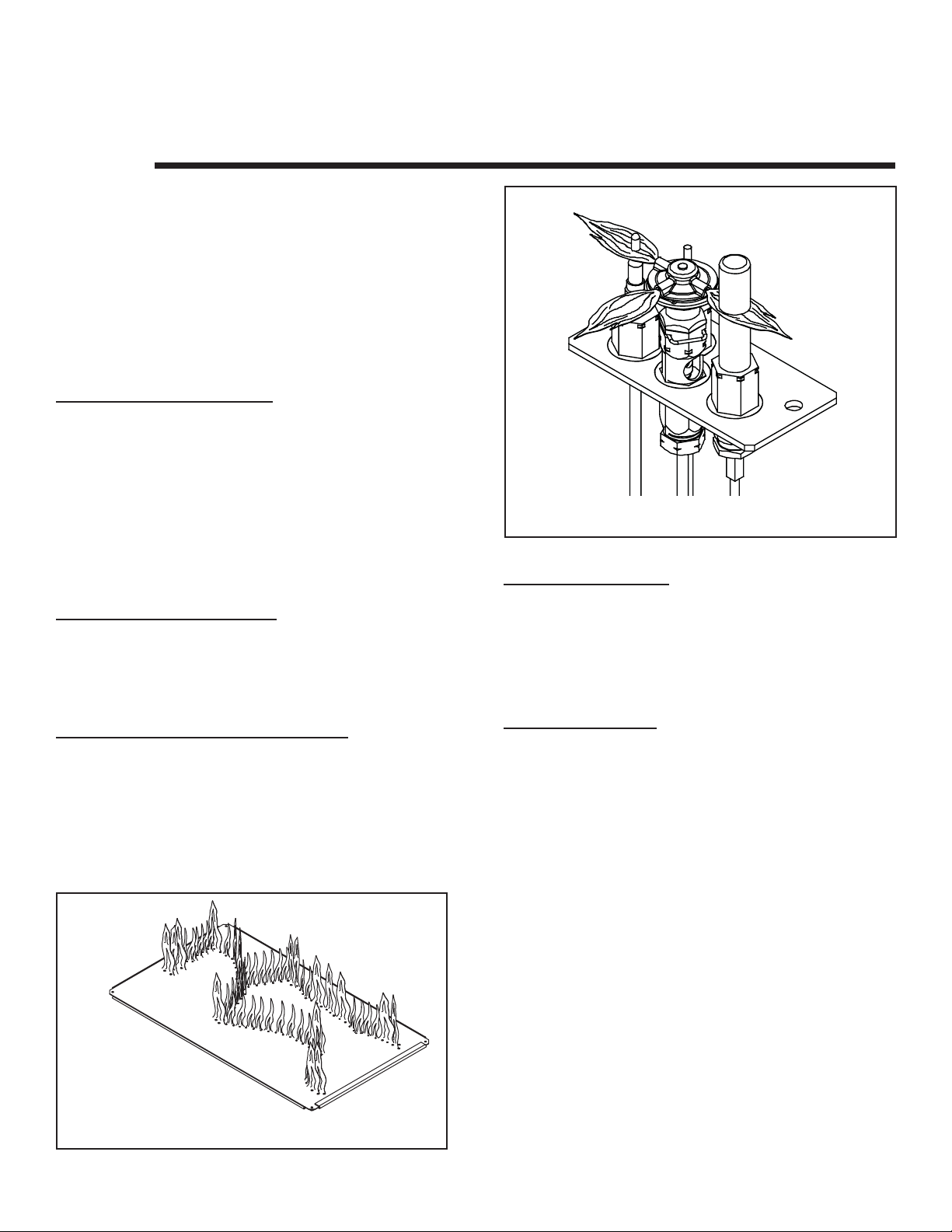
Task: Make a visual check of your stove’s fl ame patterns.
Make sure the fl ames are steady - not lifting or fl oating.
See Figure 35. The thermopile/thermocouple tips should
be covered with fl ame. See Figure 36.
STANDING PILOT
Figure 36. Pilot Flame Patterns
Checking Flue System
Frequency: Before initial use and at least annually
thereafter, more frequently if possible.
By: Qualifi ed service technician/Home owner.
Task: Inspect the external cap on a regular basis to ensure
that no debris is interfering with the fl ow of air. Inspect entire
fl ue system for proper function.
Cleaning Glass Door
Frequency: After the fi rst 3 to 4 hours of use. As neces-
sary after initial cleaning.
By: Qualifi ed Service Technician
Task: Remove and clean glass after the fi rst 3 to 4 hours
of use. After the initial cleaning, clean as necessary, particularly after adding new ember material. Film deposits on
the inside of the glass door should be cleaned off using
a household glass cleaner. NOTE: DO NOT handle or
attempt to clean the door when it is hot and DO NOT
use abrasive cleaners.
MAKE SURE THE FLAMES
ARE STEADY—NOT
LIFTING OR FLOATING.
Figure 35. Burner Flame Patterns
42
Heat & Glo • PIER/ST/L&RCOR-HVB-CE • 2068-900 Rev. K • 6/09
Page 43
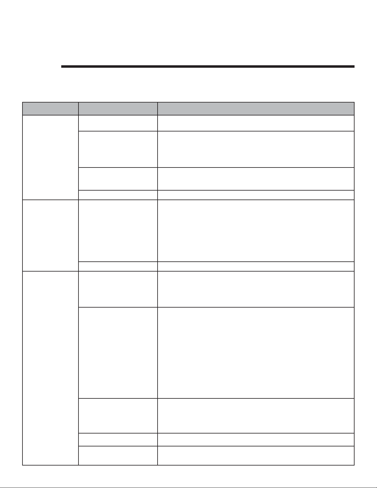
5
Troubleshooting
With proper installation, operation, and maintenance the gas fi replace will provide years of trouble-free service. If you do
experience a problem, this trouble shooting guide will assist a qualifi ed service person in the diagnosis of a problem and the
corrective action to be taken. This troubleshooting guide can only be used by a qualifi ed service technician.
Symptom Possible Cause Corrective Action
1. After repeated
triggering of
the red or black
piezo button, the
spark ignitor will
not light the pilot.
2. The pilot will
not stay lit
after carefully
following
the lighting
instructions.
3. The pilot is
burning, there is
no gas burner,
the valve knob
is in the ON
position, and the
ON/OFF switch
is in the ON
position.
a. Defective ignitor Check the spark at the electrode and pilot. If no spark and electrode wire is
properly connected, replace the ignitor.
b. Defective pilot or
misaligned electrode
(spark at electrode)
c. No gas or low gas
pressure
d. No LP in the tank Check the LP (propane) tank. You may be out of fuel.
a. Defective thermocouple Check that the pilot fl ame impinges on the thermocouple. Clean and/or adjust
b. Defective valve If thermocouple is producing more than 15 millivolts, replace faulty valve.
a. ON/OFF switch or wires
defective
b. Thermopile may not be
generating suffi cient
millivoltage
Using a match, light the pilot. If the pilot lights, turn off the pilot and trigger the
red or black piezo button again. If the pilot lights, an improper gas/air mixture
caused the bad lighting and a longer purge period is recommended. If the pilot
will not light, ensure that the gap at the electrode and pilot is 0.3 cm to have a
strong spark. If the gap is OK, replace the pilot.
Check the remote shut-off valves from the fi replace. Usually, there is a valve
near the gas main. There can be more than one (1) valve between the fi replace
and the main.
the pilot for maximum fl ame impingement.
Ensure that the thermocouple connection at the gas valve is fully inserted and
tight (hand tighten plus 1/4 turn).
Disconnect the thermocouple from the valve, place one millivolt meter lead wire
on the tip of the thermocouple and the other meter lead wire on the thermocouple
copper lead. Start the pilot and hold the valve knob in. If the millivolt reading is
less than 15mV, replace the thermocouple.
Check the ON/OFF switch and wires for proper connections. Place the jumper
wires across the terminals at the switch. If the burner comes on, replace the
defective switch. If the switch is OK, place the jumper wires across the switch
wires at the gas valve. If the burner comes on, the wires are faulty or connections
are bad.
If the pilot fl ame is not close enough physically to the thermopile, adjust the
pilot fl ame.
Be sure the wire connections from the thermopile at the gas valve terminals are
tight and that the thermopile is fully inserted into the pilot bracket.
Check the thermopile with a millivolt meter. Take the reading at TH-TP&TP
terminals of the gas valve. The meter should read 325 millivolts minimum, while
holding the valve knob depressed in the pilot position, with the pilot lit, and the
ON/OFF switch in the OFF position. Replace the faulty thermopile if the reading
is below the specifi ed minimum.
With the pilot in the ON position, disconnect the thermopile leads from the valve.
Take a reading at the thermopile leads. The reading should be 325 millivolts
minimum. Replace the thermopile if the reading is below the minimum.
c. Defective valve
d. Plugged burner orifi ce Check the burner orifi ce for stoppage. Remove stoppage.
e. Wall switch or wires are
defective
Heat & Glo • PIER/ST/L&RCOR-HVB-CE • 2068-900 Rev. K • 6/09 43
Turn the valve knob to the ON position. Place the ON/OFF switch in the ON
position. Check the millivolt meter at the thermopile terminals. The millivolt meter
should read greater than 125mV If the reading is acceptable, and if the burner
does not come on, replace the gas valve.
Follow the corrective action in Symptom and Possible Cause 1. a. above. Check
the switch and wiring. Replace where defective.
Page 44
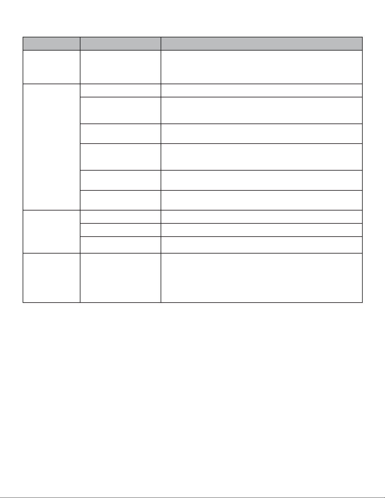
Troubleshooting continued
Symptom Possible Cause Corrective Action
4. Frequent pilot
outage problem.
a. Pilot fl ame may be too
high or too low, or blowing
(high), causing pilot safety
Clean and adjust the pilot fl ame for maximum fl ame impingement on thermocouple.
Follow lighting instructions carefully.
to drop out
5. The pilot and
a. No LP in the tank Check the LP (propane) tank. Refi ll the fuel tank.
main burner
extinguish while
in operation.
b. Inner fl ue pipe leaking
exhaust gases back into
Check for gas leaks.
the system
c. Horizontal fl ue improperly
pitched
The horizontal fl ue cap should slope down only enough to prevent any water
from entering the unit. The maximum downward slope is 0.6 cm.
d. Glass too loose and
air tight packet leaks in
Tighten the corner.
corners after usage
e. Bad thermopile or
thermocouple
f. Improper fl ue cap
installation
Replace if necessary.
Check for proper installation and freedom from debris or blockage.
6. Glass soots. a. Flame impingement Adjust the log set so that the fl ame does not excessively impinge on it.
b. Improper venturi setting Adjust the air shutter at the base of the burner.
7. Flame burns
blue and lifts off
burner.
c. Debris around venturi
a. Insuffi cient oxygen being
supplied
Inspect the opening at the base of the burner. NO MATERIAL SHOULD BE
PLACED IN THIS OPENING.
Ensure that the fl ue cap is installed properly and free of debris. Ensure that the
fl ue system joints are tight and have no leaks.
Ensure that no debris has been placed in the area at the base of, or in the area
of, the air holes in the center of the base pan beneath the burner.
Ensure that the glass is tightened properly on the unit, particularly on top
corners.
44
Heat & Glo • PIER/ST/L&RCOR-HVB-CE • 2068-900 Rev. K • 6/09
Page 45
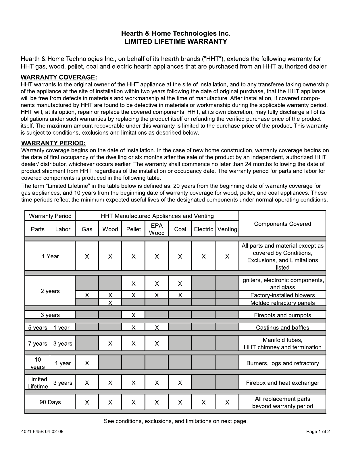
Î
Limited Lifetime Warranty
Heat & Glo • PIER/ST/L&RCOR-HVB-CE • 2068-900 Rev. K • 6/09 45
Page 46
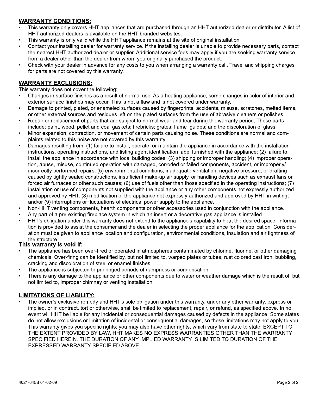
46
Heat & Glo • PIER/ST/L&RCOR-HVB-CE • 2068-900 Rev. K • 6/09
 Loading...