

Page 1

Models:
Pier-38HV
ST-38HV
WARNING: IF THE INFORMATION
IN THESE INSTRUCTIONS IS NOT
FOLLOWED EXACTLY, A FIRE OR
EXPLOSION MAY RESULT CAUSING PROPERTY DAMAGE, PERSONAL INJURY, OR DEATH.
- Do not store or use gasoline or other flammable vapors and liquids in the vicinity of this
or any other appliance.
- What to do if you smell gas
Do not try to light any appliance.
Do not touch any electrical switch.
Do not use any phone in your building.
Immediately call your gas supplier from a
neighbor's phone. Follow the gas supplier's
instructions.
If you cannot reach your gas supplier, call
the fire department.
- Installation and service must be performed by a
qualified installer, service agency, or the gas
supplier.
Installers Guide
Underwriters
Laboratories Listed
READ THIS MANUAL BEFORE INSTALLING OR
OPERATING THIS APPLIANCE. THIS INSTALLERS
GUIDE MUST BE LEFT WITH APPLIANCE FOR
FUTURE REFERENCE.
WARNING: IMPROPER INSTALLATION, ADJUSTMENT, ALTERATION,
SERVICE OR MAINTENANCE CAN
CAUSE INJURY OR PROPERTY DAMAGE. REFER TO THIS MANUAL. FOR
ASSISTANCE OR ADDITIONAL INFORMATION CONSULT A QUALIFIED INSTALLER, SERVICE AGENCY, OR THE
GAS SUPPLIER.
1. This appliance may be installed in an aftermarket, permanently located, manufactured (mobile) home, where not prohibited by local codes.
2. This appliance is only for use with the type
of gas indicated on the rating plate. This
appliance is not convertible for use with
other gases, unless a certified kit is used.
Printed in U.S.A. Copyright 2001,
Heat-N-Glo, a division of Hearth Technologies Inc.
20802 Kensington Boulevard, Lakeville, MN 55044
This product is covered by one or more of the following patents: (United States) 4,112,913; 4,408,594; 4,422,426; 4,424,792; 4,520,791; 4,793,322;
4,852,548; 4,875,464; 5,000,162; 5,016,609; 5,076,254 5,191,877; 5,218,953; 5,328,356; 5,429,495; 5,452,708; 5,542,407; 5,613,487; (Australia)
543790; 586383; (Canada) 1,123,296; 1,297,746; 2,195,264; (Mexico) 97-0457; (New Zealand) 200265; or other U.S. and foreign patents pending.
Please contact your Heat-N-Glo dealer for any
questions or concerns. For the number of your
nearest Heat-N-Glo dealer, please call 952-985-6000.
285-900D 5/01
1
Page 2

SAFETY AND WARNING INFORMATION
READ and UNDERSTAND all instructions carefully
!
before starting the installation. FAILURE TO
FOLLOW these installation instructions may result
in a possible fire hazard and will void the warranty.
Prior to the first firing of the fireplace, READ the
!
Using Your Fireplace section of the Owners Guide.
DO NOT USE this appliance if any part has been
!
under water. Immediately CALL a qualified service
technician to inspect the unit and to replace any part
of the control system and any gas control which has
been under water.
THIS UNIT IS NOT FOR USE WITH SOLID FUEL.
!
Installation and repair should be PERFORMED by a
qualified service person. The appliance and venting
!
system should be INSPECTED before initial use
and at least annually by a professional service
person. More frequent cleaning may be required
due to excessive lint from carpeting, bedding
material, etc. It is IMPERATIVE that the units
control compartment, burners, and circulating air
passageways BE KEPT CLEAN to provide for
adequate combustion and ventilation air.
These units MUST use one of the vent systems
!
described in the Installing the Fireplace section of
the Installers Guide. NO OTHER vent systems or
components MAY BE USED.
This gas fireplace and vent assembly MUST be
!
vented directly to the outside and MUST NEVER be
attached to a chimney serving a separate solid fuel
burning appliance. Each gas appliance MUST USE
a separate vent system. Common vent systems are
PROHIBITED.
INSPECT the external vent cap on a regular basis to
!
make sure that no debris is interfering with the air
flow.
The glass door assembly MUST be in place and
!
sealed, and the trim door assembly MUST be in
place on the fireplace before the unit can be placed
into safe operation.
DO NOT OPERATE this appliance with the glass
!
door removed, cracked, or broken. Replacement of
the glass door should be performed by a licensed
or qualified service person. DO NOT strike or slam
the glass door.
Always KEEP the appliance clear and free from
!
combustible materials, gasoline, and other
flammable vapors and liquids.
NEVER OBSTRUCT the flow of combustion and
!
ventilation air. Keep the front of the appliance
CLEAR of all obstacles and materials for servicing
and proper operations.
Due to the high temperature, the appliance should
be LOCATED out of traffic areas and away from
!
furniture and draperies. Clothing or flammable
material SHOULD NOT BE PLACED on or near the
appliance.
Children and adults should be ALERTED to the
!
hazards of high surface temperature and should
STAY AWAY to avoid burns or clothing ignition.
Young children should be CAREFULLY SUPERVISED
when they are in the same room as the appliance.
The glass door assembly SHALL ONLY be
!
replaced as a complete unit, as supplied by the gas
fireplace manufacturer. NO SUBSTITUTE material
may be used.
DO NOT USE abrasive cleaners on the glass door
!
assembly. DO NOT ATTEMPT to clean the glass
door when it is hot.
Turn off the gas before servicing this appliance. It is
!
recommended that a qualified service technician
perform an appliance check-up at the beginning of
each heating season.
Any safety screen or guard removed for servicing
!
must be replaced before operating this appliance.
DO NOT place furniture or any other combustible
!
household objects within 36 inches of the fireplace
front.
2
Page 3

Table of Contents
Safety and Warning Information ..................................... 2
Service Parts Lists .......................................................... 4
u
Section 1: Approvals and Codes .................................... 8
Appliance Certification........................................................ 8
Installation Codes ............................................................... 8
High Altitude Installations .................................................... 8
Section 2: Getting Started .............................................. 9
Introducing the Heat-N-Glo Gas Fireplaces ....................... 9
Pre-installation Preparation ................................................ 9
Section 3: Installing the Fireplace ............................... 12
Constructing the Fireplace Chase ................................... 12
Step 1 Locating the Fireplace ....................................... 12
Step 2 Framing the Fireplace ....................................... 13
u
Step 3 Installing the Vent System ................................. 15
A. Vent System Approvals ................................ 15
u
B. Installing Vent Components ......................... 22
C. Vent Termination .......................................... 25
Step 4 Positioning, Leveling, and
Securing the Fireplace ...................................... 28
Step 5 The Gas Control Systems ................................. 28
Step 6 The Gas Supply Line ......................................... 29
Step 7 Gas Pressure Requirements ............................ 29
Step 8 Wiring the Fireplace .......................................... 30
Step 9 Finishing ............................................................ 31
Step 10 Installing Trim, Logs, and Ember Material ......... 32
Installing the Trim .............................................. 32
Positioning the Logs ..........................................32
Placing the Ember Material ............................... 32
Glass Specifications .......................................... 33
Step 11 Before Lighting the Fireplace .............................33
Step 12 Lighting the Fireplace ........................................33
After the Installation .......................................................... 33
Section 4: Maintaining and Servicing
u = Contains updated information.
Your Fireplace ............................................. 34
3
Page 4

1
Approvals and Codes
Appliance Certification
The Heat-N-Glo fireplace models discussed in this Installers
Guide have been tested to certification standards and listed
by the applicable laboratories.
Certification
MODEL: PIER-38HV, ST-38HV
LABORATORY: Underwriters Laboratories
TYPE: Direct Vent Gas Fireplace
STANDARD: ANSI Z21.50CGA2.22UL307B
Installation Codes
The fireplace installation must conform to local codes. Before
installing the fireplace, consult the local building code
agency to ensure that you are in compliance with all
applicable codes, including permits and inspections.
In the absence of local codes, the fireplace installation must
conform to the National Fuel Gas Code ANSI Z223.1 (in
the United States) or the CAN/CGA-B149 Installation Codes
(in Canada). The appliance must be electrically grounded
in accordance with local codes or, in the absence of local
codes with the National Electric Code ANSI/NFPA No. 70
(in the United States), or to the CSA C22.1 Canadian Electric
Code (in Canada).
High Altitude Installations
U.L. Listed gas fireplaces are tested and approved for
elevations from 0 to 2,000 feet in the U.S.A. and from 0 to
4,500 feet in Canada.
When installing this fireplace at an elevation above 2,000
feet (in the United States), it may be necessary to decrease
the input rating by changing the existing burner orifice to a
smaller size. Input should be reduced four percent (4%) for
each 1,000 feet above sea level, unless the heating value of
the gas has been reduced, in which case this general rule
will not apply.
When installing this fireplace at an elevation between 2,000
and 4,500 feet (in Canada), the input rating must be reduced
by ten percent (10%).
When installing this fireplace at an elevation above 4,500
feet (in Canada), check with local authorities.
Consult your local gas utility for assistance in determining
the proper orifice for your location.
These models may be installed in a bedroom or bed-sitting
room in the U.S.A. and Canada.
Heat-N-Glo Quality
Systems registered
by SGS ICS
8
Page 5

2
Getting Started
Introducing the Heat-N-Glo Gas Fireplaces
Heat-N-Glo direct vent gas fireplaces are designed to operate with all combustion air siphoned from outside of the
building and all exhaust gases expelled to the outside.
The information contained in this Installers Guide, unless
noted otherwise, applies to all models and gas control
systems. Gas fireplace diagrams, including the dimensions,
are shown in this section.
Pre-install Preparation
This gas fireplace and its components are tested and safe
when installed in accordance with this Installers Guide.
Report to your dealer any parts damaged in shipment,
particularly the condition of the glass. Do not install any
unit with damaged, incomplete, or substitute parts.
The vent system components are shipped in separate
packages. The gas logs are packaged separately and must
be field installed.
Read all of the instructions before starting the
installation. Follow these instructions carefully during
the installation to ensure maximum safety and benefit.
Failure to follow these instructions will void the
owners warranty and may present a fire hazard.
Warranty
The Heat-N-Glo Warranty will be voided by, and Heat-N-Glo
disclaims any responsibility for, the following actions:
Installation of any damaged fireplace or vent system com-
ponent.
Modification of the fireplace or direct vent system.
Installation other than as instructed by Heat-N-Glo.
Improper positioning of the gas logs or the glass door.
Installation and/or use of any component part not manu-
factured and approved by Heat-N-Glo, not withstanding
any independent testing laboratory or other party approval
of such component part or accessory.
ANY SUCH ACTION MAY POSSIBLY CAUSE A FIRE
HAZARD.
When planning a fireplace installation, its necessary to
determine:
Where the unit is to be installed.
The vent system configuration to be used.
Gas supply piping.
Electrical wiring.
Framing and finishing details.
Whether optional accessories devices such as a fan,
wall switch, or remote control are desired.
If the fireplace is to be installed on carpeting or tile, or on
any combustible material other than wood flooring, the
fireplace must be installed on a metal or wood panel that
extends the full width and depth of the fireplace.
9
Page 6

Ø
6 5/8
(168mm)
11 5/ 16
(287mm)
25 7/8
(657mm)
VENT COLLAR
38 5/8
(981mm)
31 3/16
(792mm)
36 1/16
(915mm)
TOP STANDOFFS
TOP
GRILL
SIDE
GLASS
DOOR
28 3/16
(716mm)
35 3/16
(894mm)
2
(52mm)
3 3/8
(85mm)
ELECTRICAL
ACCESS
GAS LINE
ACCESS
22 11/16
(576mm)
VENT COLLAR
2
(52mm)
3 1/16
(79mm)
ELECTRICAL
ACCESS
GAS LINE
ACCESS
Figure 1. Diagram of the PIER-38HV
END GLASS
DOOR
BOTTOM
GRILL
GAS CONTROLS
& LABELS
10
Page 7

Ø6 5/8
(168mm)
11 5/16
(287mm)
25 7/8
(657mm)
VENT COLLAR
38 5/8
(981mm)
35 3/16
(894mm)
31 3/16 (792mm)
38 1/4 (972mm)
TOP STANDOFFS
TOP
GRILL
29 1/8
(739mm)
(52mm)
3 3/8
(85mm)
ELECTRICAL
ACCESS
GAS LINE
2
ACCESS
22 11/16
(576mm)
3 1/16
(79mm)
VENT COLLAR
2
(52MM)
ELECTRICAL
ACCESS
Figure 2. Diagram of the ST-38HV
GAS LINE
ACCESS
GLASS
DOOR
BOTTOM
GRILL
GAS CONTROLS
& LABELS
11
Page 8

3
Installing the Fireplace
36”
PIER-38HV
Constructing the Fireplace Chase
A chase is a vertical box-like structure built to enclose the
gas fireplace and/or its vent system. Vertical vents that run
on the outside of a building may be, but are not required to
be, installed inside a chase.
CAUTION: TREATMENT OF FIRESTOP SPACERS AND
CONSTRUCTION OF THE CHASE MAY VARY WITH THE
TYPE OF BUILDING. THESE INSTRUCTIONS ARE NOT
SUBSTITUTES FOR THE REQUIREMENTS OF LOCAL
BUILDING CODES. THEREFORE, YOUR LOCAL BUILDING CODES MUST BE CHECKED TO DETERMINE THE
REQUIREMENTS FOR THESE STEPS.
Factory-built fireplace chases should be constructed in the
manner of all outside walls of the home to prevent cold air
drafting problems. The chase should not break the outside
building envelope in any manner.
This means that the walls, ceiling, base plate and cantilever
floor of the chase should be insulated. Vapor and air infiltration barriers should be installed in the chase as per regional
codes for the rest of the home. Additionally, Heat-N-Glo recommends that the inside surfaces be sheetrocked and taped
for maximum air tightness.
To further prevent drafts, the firestops should be caulked to
seal gaps. Gas line holes and other openings should be
caulked or stuffed with insulation. If the unit is being installed on a cement slab, we recommend that a layer of
plywood be placed underneath to prevent conducting cold
up into the room. Be sure to include spark arrestors for
woodburning units if they are required.
36”
36”
ST-38HV
36”
Figure 3. Fireplace Dimensions, Locations,
and Space Requirements
Minimum Clearances from the Fireplace to
Combustible Materials
Inches mm
Glass Sides or Ends.......... 3 6 ................. 91 4
Floor....................................... 0 .................... 0
Rear Vent............................... 0 .................... 0
Metal Sides or Ends ............ 0 .................... 0
Top ....................................... 3 1/2 ...............8 9
Ceiling*................................. 3 6 ................. 91 4
*The clearance to the ceiling is measured from the top
of the unit, excluding the stand-offs (see Figure 34).
THE CHASE SHOULD BE CONSTRUCTED SO THAT ALL
CLEARANCES TO THE FIREPLACE ARE MAINTAINED
AS SPECIFIED WITHIN THIS INSTALLERS GUIDE.
Step 1. Locating the Fireplace
Space and clearance requirements for locating a fireplace
within a room (see Figure 3).
Clearance Requirements
The top, back, and sides of the fireplace are defined by
stand-offs. The minimum clearance to a perpendicular wall
extending past the face of the fireplace is one inch (25mm).
The metal ends of the fireplace may NOT be recessed into
combustible construction.
Minimum Clearances from the Vent Pipe to
Combustible Materials
Inches mm
Vertical Sections. ............. 1 ................... 2 5
Horizontal Sections
Top ......................................... 3 ................... 75
Bottom .................................. 1 ................... 25
Sides..................................... 1 ................... 25
At Wall Firestops
Top ...................................... 2 1/2 ...............6 4
Bottom ................................. 1/2 ................. 1 3
Sides..................................... 1 ................... 2 5
For minimum clearances of direct vent termination (see Figures 25 and 26).
12
Page 9

Step 2. Framing the Fireplace
Fireplace framing can be built before or after the fireplace is
set in place. Framing should be positioned to accommodate wall coverings and fireplace facing material. The diagram below shows framing reference dimensions.
CAUTION: MEASURE FIREPLACE DIMENSIONS AND
VERIFY FRAMING METHODS AND WALL COVERING
DETAILS BEFORE FRAMING.
WARNING: FRAMING DIMENSIONS ASSUME
!
USE OF 1/2 INCH THICK WALL COVERING
MATERIALS ON EXTERIOR OF FRAMING ONLY
AND NO SHEET ROCK ON INTERIOR OF FRAMING.
Shows center of 10 x 10 vent framing holes.
The center of the hole is 1 inch (25.4mm)
above the center of the horizontal vent pipe.
37 1/8
(943mm)
Framing should be constructed
of 2 X 4 lumber or heavier.
*NOTE:
Review details of Figure 5 BEFORE
constructing framing. The dimensions in Figure 4 do not include positions of venting and firestops.
*35 7/8 (911mm)
1/2 SHEET ROCK
35 3/4
(908mm)
5/8 SHEETROCK
38 1/2
(978mm)
38 3/4
(984mm)
21 11/16
(551mm)
1/2 SHEET ROCK
21 7/16
(545mm)
5/8 SHEET ROCK
38 3/4
(984mm)
21 11/16
(551mm)
1/2 SHEET ROCK
21 7/16
(545mm)
5/8 SHEET ROCK
Figure 4. Framing Dimensions*
13
Page 10
ST-38HV
PIER- 38 HV
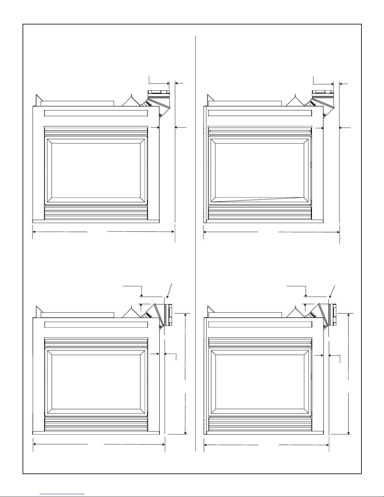
Vertical Vent Runs
41 1/2”
(1054mm)
1” (25mm)
PIPE CLEARANCE
”
4
Vertical Vent Runs
1” (25mm)
PIPE CLEARANCE
)
m
m
2
0
1
(
40 3/8”
(1026mm)
)
m
”
m
4
2
0
1
(
Horizontal Vent Runs
3” (75mm)
PIPE CLEARANCE
40”
(1016mm)
FIRESTOP
1 1/2”
(38mm)
36 1/8”
(918mm)
Horizontal Vent Runs
3” (75mm)
PIPE CLEARANCE
37 7/8”
(962mm)
FIRESTOP
1 1/2”
(38mm)
36 1/8”
(918mm)
Figure 5. Vertical and Horizontal Vent Runs for ST-38HV and PIER-38HV.
14
Page 11
Step 3. Installing the Vent System
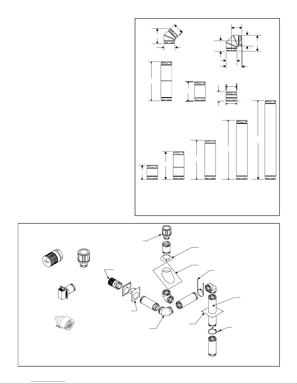
A. Vent System Approvals
These models are approved to use SL-series direct
vent pipe components and terminations. Approved
vent system components are labeled for identification. This pipe is tested and listed as an approved
component of the fireplace. The pipe is tested to be
run inside an enclosed wall. There is no requirement
for inspection openings at each joint within the wall.
There is no required pitch for horizontal vent runs.
NO OTHER VENTING SYSTEMS OR COMPONENTS MAY BE USED.
Detailed installation instructions are included with each
vent termination kit and should be used in conjunction
with this Installers Guide. The drawing below shows
vent system components and terminations.
The flame and ember appearance may vary based
on the type of fuel burned and the venting configuration used.
17-24
9 1/4
SL-17/24D
(SL17-24D)
SL-45D
6 1/2
6 5/8
11 3/4
6 5/8
6 3/8
5 3/4
6 3/8
SL-90D
SL-06DSL-12D
6 1/2
6 5/8
6 1/2
9 5/8
9 5/8
47 3/4
Identifying Vent Components
The vent systems installed on this gas fireplace may
include one, two, or three 90° elbow assemblies. The
relationships of vertical rise to horizontal run in vent
configurations using 90° elbows MUST BE strictly
adhered to. The rise to run relationships are shown
in the venting drawings and tables. Refer to the diagrams on the next several pages.
NOTE: Two 45° elbows may be used in place of
one 90° elbow. Rise to run ratios in the vent
system must be followed if 45° elbows are used.
Vent system
termination kits
HORIZONTAL
SLK-01D
SLK-TVCD
TERMINATION
8 3/4
VERTICAL
TERMINATION
35 3/4
23 3/4
12-17
SL-09D
SL-12/17D (SL12-17D)
SL-24D
SL-36D
SL-48D
NOTE: PIPES OVERLAP 1-3/8 INCHES (34.93mm) AT EACH JOINT.
Figure 6. SL-Series Direct Vent Component Specifications
(4-inch inner pipe / 6 5/8-inch outer pipe)
Vent system components
STORM COLLAR
ROOF FLASHING
HORIZONTAL PIPE
SUPPORT
SLK-01TRD
PVK-80
Figure 7. Vent Components and Terminations
WA LL FIRESTOP
90 DEGREE
ELBOW
15
CEILING
FIRESTOP
PIPE LENGTH
WALL BRACKET
To Unit
Page 12
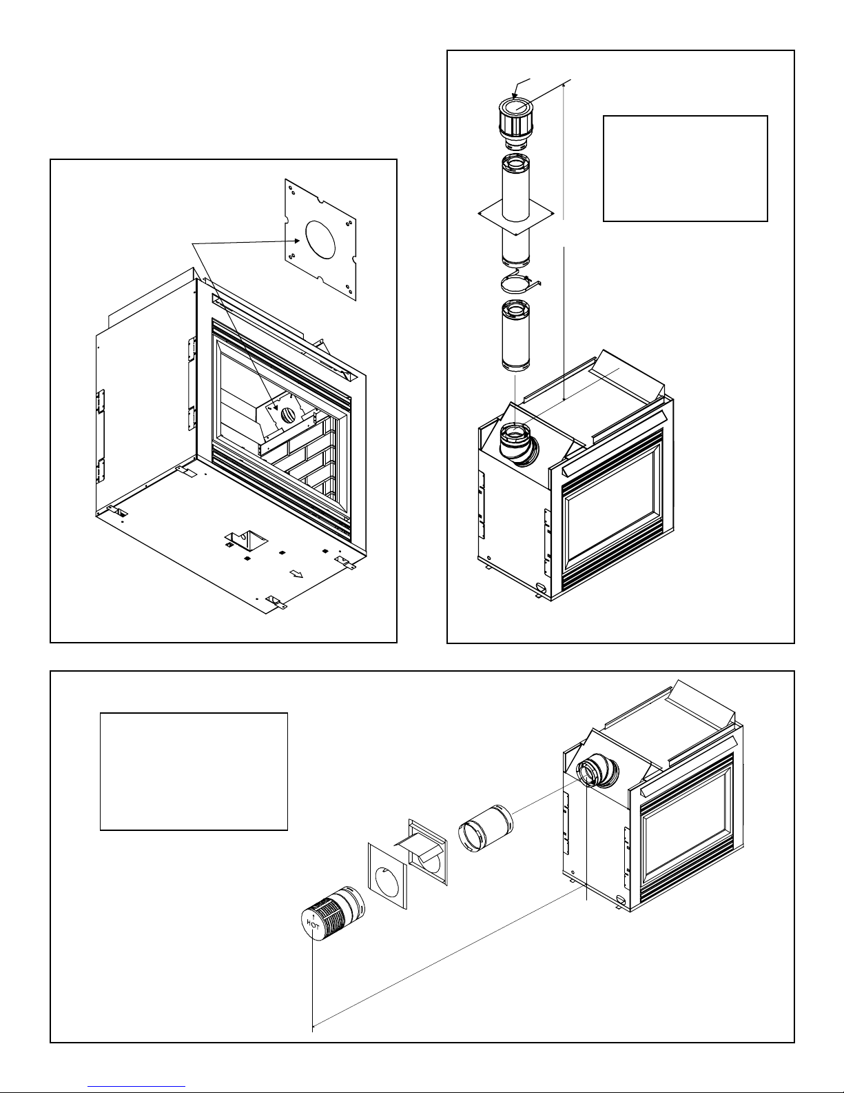
NOTE: If the vertical vent component is 10 feet or more,
you may want to install the vertical baffle to improve flame
appearance. Vertical baffle kit (BAF-VERT) is located in
the manual bag.Center the vertical baffle on the four inch
flue and with self tapping screws secure the baffle to the
inside of the firebox (see Figure 8).
CAP
STRAIGHT UP
VERTICAL VENTING
V (FT.)
40' MAX. (12.4 M)
VERTICAL BAFFLE
KIT (BAF-VERT)
Figure 8.
Vertical Baffle Kit
V
NOTE: For vertical vent runs
of 10 feet or greater the vertical baffle kit (BAF-VERT)
may be required to improve
flame appearance.
Figure 9. Straight Up Vertical Venting
STRAIGHT OUT
HORIZONTAL VENTING
H
Max. Run
24" (610 mm)
Figure 10.
Straight Out Horizontal Venting
H
16
Page 13
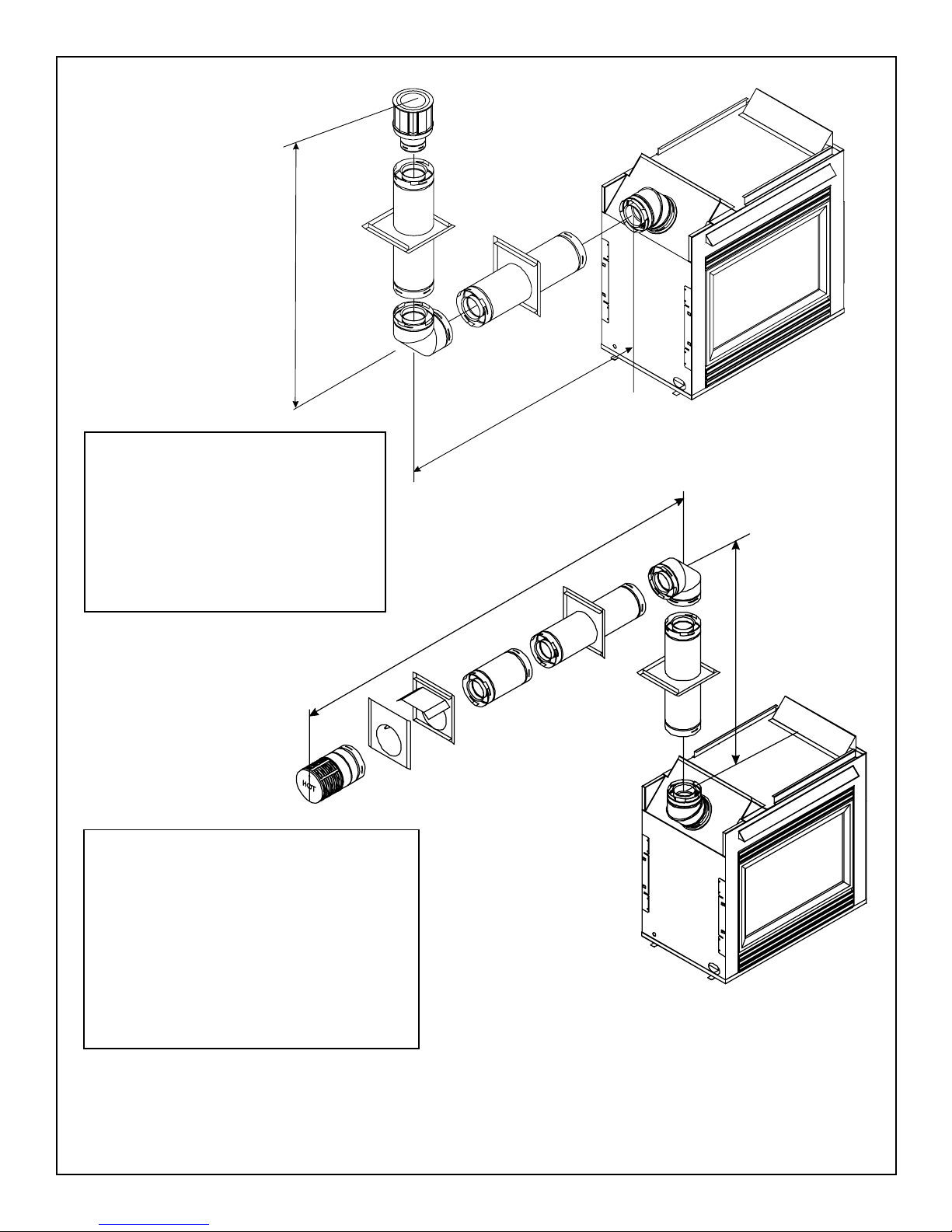
V
VENTING WITH ONE (1) 90° ELBOW
V (FT.) H (FT.)
4.5' MIN. (1.37m) 3' MAX. (.914m)
6' MIN. (1.86m) 4' MAX. (1.22m)
8' MIN. (2.4m) 5' MAX. (1.5m)
5' MAX. (1.5m)
V + H = 37 MAX. (11.3m)
H
H
V
VENTING WITH ONE (1) 90° ELBOW
V (FT.) H (FT.)
1' MIN. (305mm) 2' MAX. (610mm)
2' MIN. (610mm) 4' MAX. (1.22m)
3' MIN. (914mm) 6' MAX. (1.86m)
4' MIN. (1.22m) 8' MAX. (2.44m)
5 MIN. (1.5m) 10 MAX. (3.05m)
6 MIN. (1.86m) 12 MAX. (3.6m)
7 MIN. (2.13m) 14' MAX. (4.27m)
14' MAX. (4.27m)
V + H = 37 MAX. (11.3m)
NOTE: For vertical vent runs of 10 feet or greater the vertical baffle
kit (BAF-VERT) may be required to improve flame appearance.
Figure 11. Venting with One 90° Elbow
17
Page 14
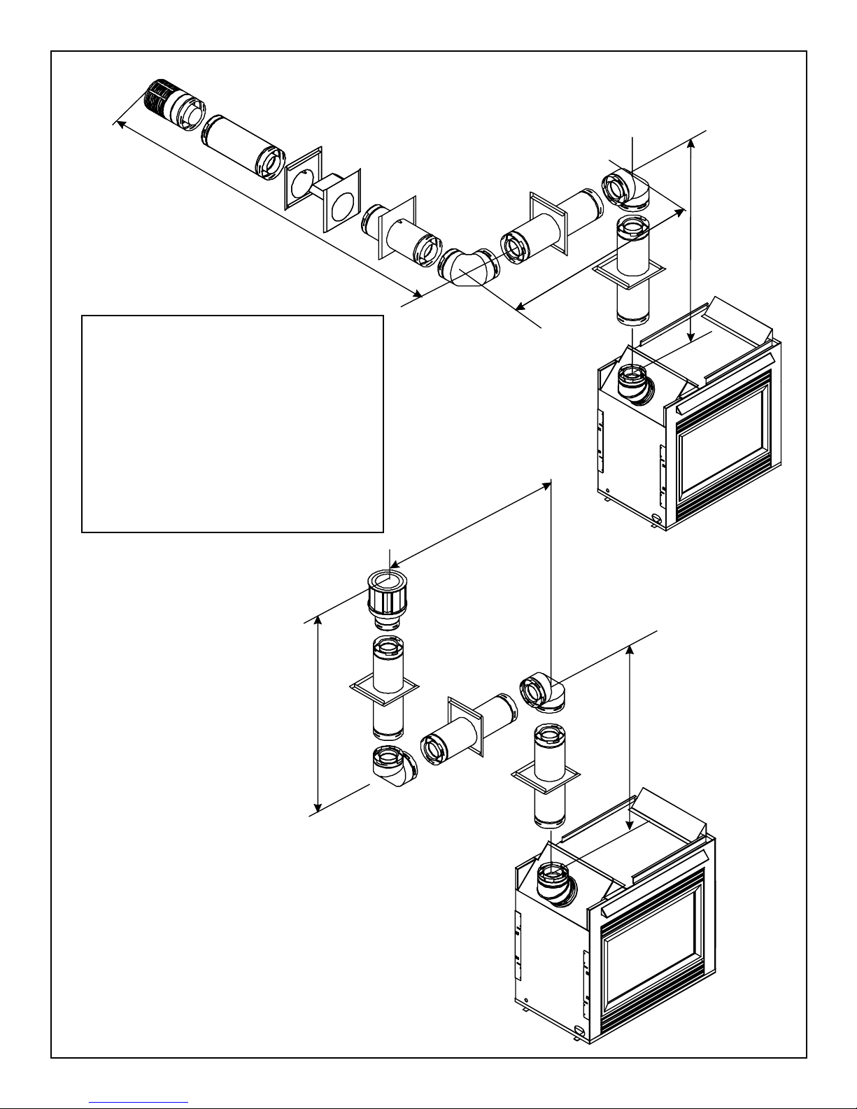
H
11
VENTING WITH TWO (2) 90° ELBOWS
V (FT.) H + H1 (FT.)
1' MIN. (305mm) 2' MAX. (610mm)
2' MIN. (610mm) 4' MAX. (1.22m)
3' MIN. (914mm) 6' MAX. (1.86m)
4' MIN. (1.22m) 8' MAX. (2.44m)
5 MIN. (1.5m) 10 MAX. (3.04m)
6 MIN. (1.86m) 12 MAX. (3.6m)
7 MIN. (2.13m) 14' MAX. (4.27m)
14' MAX. (4.27m)
V + H = 37 MAX. (11.3m)
V
H
H
NOTE: For vertical vent runs of 10 feet or greater the vertical baffle kit
(BAF-VERT) may be required to improve flame appearance.
Figure 12. Venting with Two 90° Elbows
V
11
18
V
Page 15
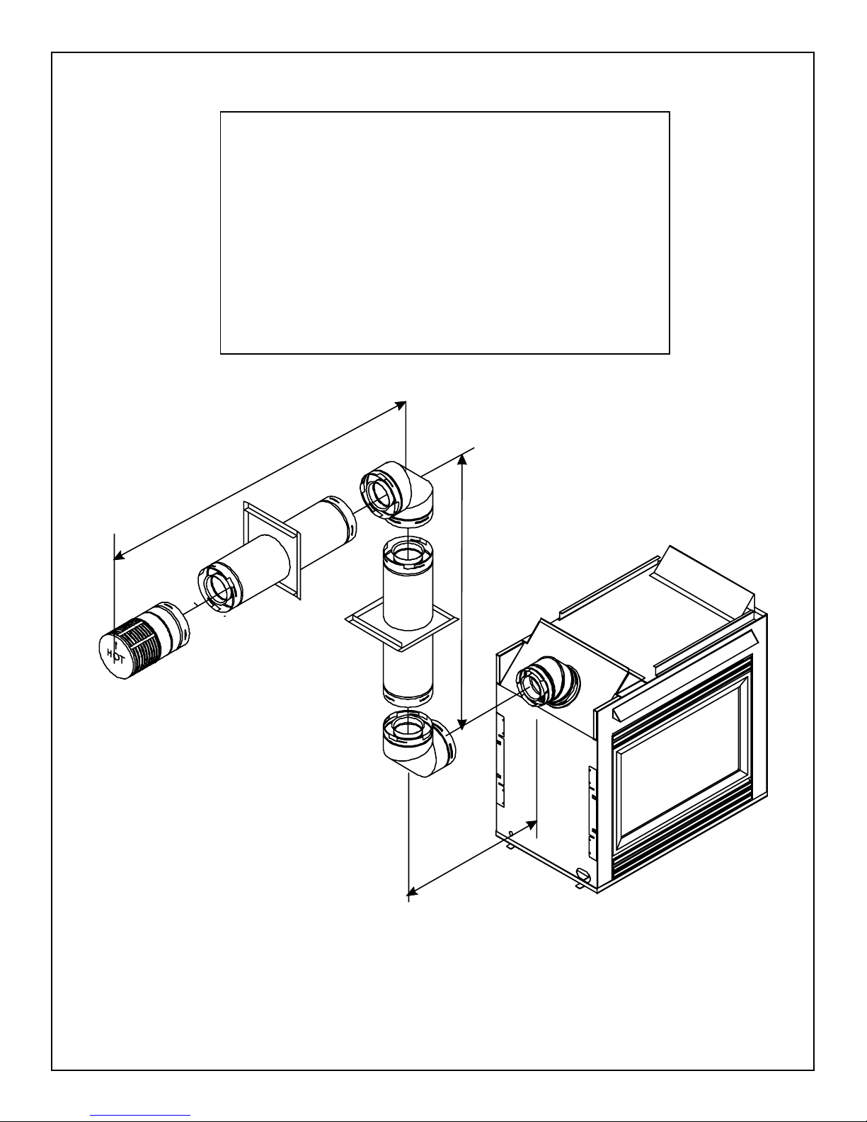
VENTING WITH TWO (2) 90° ELBOWS
V H H + H
1´ MIN. (305 mm) 2´ MAX. (610 mm) 2´ MAX. (610 mm)
2´ MIN. (610 mm) 2´ MAX. (610 mm) 4´ MAX. (1.22 m)
3´ MIN. (914 mm) 2´ MAX. (610 mm) 6´ MAX. (1.86 m)
4´ MIN. (1.22 m) 2´ MAX. (610 mm) 8´ MAX. (2.4 m)
5´ MIN. (1.52 m) 2´ MAX. (610 mm) 10´ MAX. (3.04 m)
6´ MIN. (1.86 m) 2´ MAX. (610 mm) 12´ MAX. (3.65 m)
7´ MIN. (2.13 m) 2´ MAX. (610 mm) 14´ MAX. (4.26 m)
14´ MAX. (4.26 m)
H
11
V + H + H
= 37 MAX. (11.3 m)
1
1
H
V
NOTE: For vertical vent runs of 10 feet or greater the vertical baffle
kit (BAF-VERT) may be required to improve flame appearance.
Figure 13. Venting with Two (2) 90° Elbows
19
Page 16
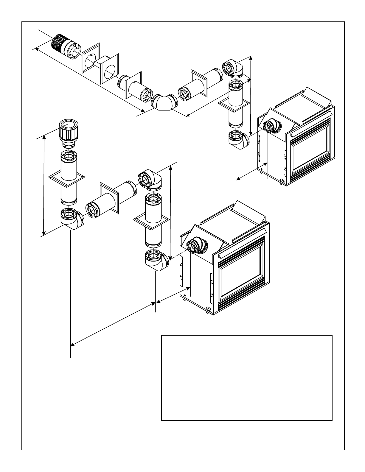
V
H
22
V
H
11
H
11
V
H
11
NOTE: For vertical vent runs of 10 feet or
greater the vertical baffle kit (BAF-VERT) may
be required to improve flame appearance.
Figure 14. Venting with Three 90° Elbows
H
VENTING WITH THREE (3) 90° ELBOWS
V H H + H
1´ MIN. (305 mm) 2´ MAX. (610 mm) 2´ MAX. (610 mm)
2´ MIN. (610 mm) 2´ MAX. (610 mm) 4´ MAX. (1.22 m)
3´ MIN. (914 mm) 2´ MAX. (610 mm) 6´ MAX. (1.86 m)
4´ MIN. (1.22 m) 2´ MAX. (610 mm) 8´ MAX. (2.4 m)
5´ MIN. (1.52 m) 2´ MAX. (610 mm) 10´ MAX. (3.04 m)
6´ MIN. (1.86 m) 2´ MAX. (610 mm) 12´ MAX. (3.65 m)
7´ MIN. (2.13 m) 2´ MAX. (610 mm) 14´ MAX. (4.26 m)
V + H + H
= 37 MAX. (11.3 m)
1
20
1
14´ MAX. (4.26 m)
Page 17
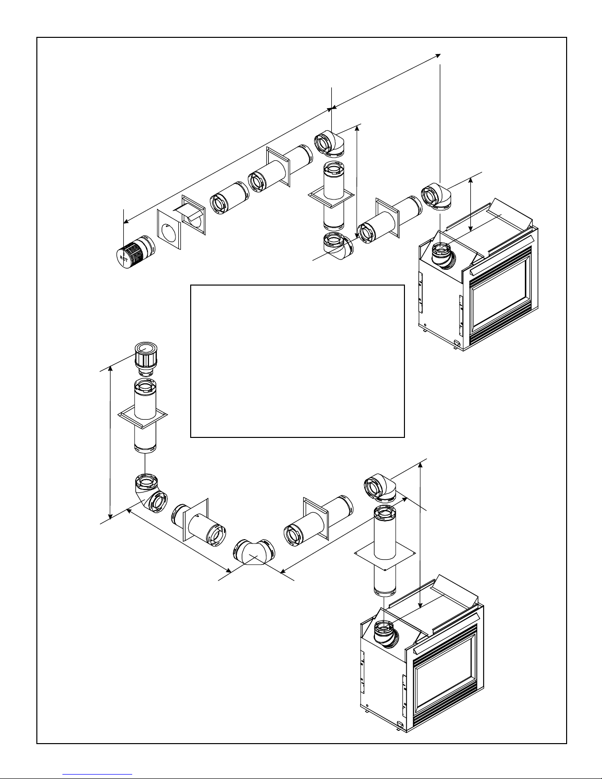
H
H
11
V
11
V
VENTING WITH THREE (3) 90° ELBOWS
V (FT.) H + H1 (FT.)
1' MIN. (305mm) 2' MAX. (610mm)
2' MIN. (610mm) 4' MAX. (1.22m)
3' MIN. (914mm) 6' MAX. (1.86m)
4' MIN. (1.22m) 8' MAX. (2.44m)
5 MIN. (1.5m) 10 MAX. (3.04m)
6 MIN. (1.86m) 12 MAX. (3.6m)
7 MIN. (2.13m) 14' MAX. (4.27m)
14' MAX. (4.27m)
V
11
V + H = 37 MAX. (11.3m)
H
11
NOTE: For vertical vent runs of 10 feet or
greater the vertical baffle kit (BAF-VERT) may
be required to improve flame appearance.
Figure 15. Venting with Three 90° Elbows
21
H
V
Page 18
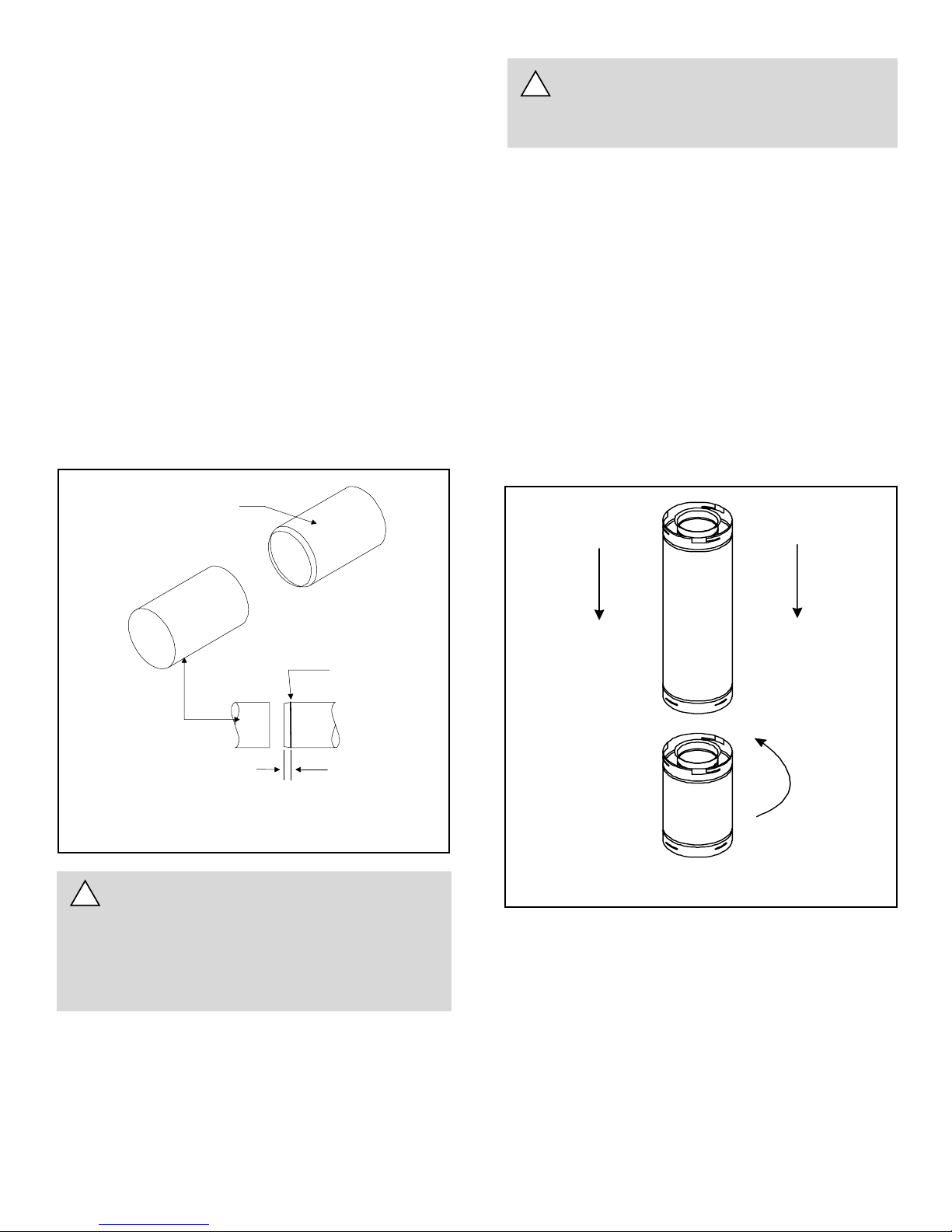
B. Installing Vent Components
1. Attach the First Vent Component to the
Starting Collars
To attach the first vent component to the starting collars
of the fireplace:
Apply a 3/8 inch (9.5mm) bead of stove cement around
the 5 inch (127mm) fireplace starting collar.
WARNING: ENSURE THAT THE FIBERGLASS
!
ROPE GASKET SUPPLIED WITH THE
FIREPLACE SEALS BETWEEN THE FIRST VENT
COMPONENT AND THE OUTER FIREPLACE WRAP.
If the installation is for a termination cap attached directly
to the fireplace, skip to the sections, Install Firestops and
Vent Termination.
Make sure that the fireplace rope gasket supplied with
the fireplace seals between the first 8-5/8 inch (219mm)
vent component and the outer fireplace wrap.
Lock the vent components into place by sliding the con-
centric pipe sections with four (4) equally spaced interior beads into the fireplace collar or previously installed component end with four (4) equally spaced indented sections.
When the internal beads of each 6-5/8 inch (168mm)
outer pipe line up, rotate the pipe section clockwise about
one-quarter (1/4) turn. The vent pipe is now locked together.
STARTING
COLLAR
STOVE
SEALANT
BEAD
2. Continue Adding Vent Components
To continue adding vent components in accordance with
the pre-planned vent system configuration:
Ensure that each succeeding vent component is securely
fitted and locked into the preceding component in the
vent system.
90° elbows may be installed and rotated to any point
around the preceding components vertical axis. If an
elbow does not end up in a locked position with the preceding component, attach with a minimum of two (2) sheet
metal screws. Continue adding vent components, locking
each succeeding component into place (see Figure 17).
FIRST VENT
COMPONENT
1 INCH
(25.4mm)
Figure 16. Attaching the First Vent Component
to the Starting Collars
WARNING: A 3/8 INCH (9.5 MM) BEAD OF
!
STOVE CEMENT MUST BE PLACED AROUND
THE 4 INCH (102MM) FIREPLACE STARTING COLLAR BEFORE ATTACHING THE FIRST VENT COMPONENT. FAILURE TO SEAL THIS JOINT MAY
CAUSE THE FIREPLACE TO OPERATE IMPROPERLY. SEE FIGURE 16.
Figure 17. Adding Venting Components
22
Page 19
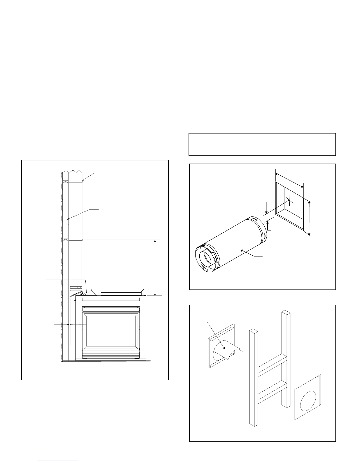
3. Install Support Brackets
For Horizontal Runs - The vent system must be sup-
ported every five (5) feet of horizontal run by a horizontal pipe
support.
To install support brackets for horizontal runs:
Place the pipe supports around the vent pipe.
Nail the pipe supports to the framing members.
For Vertical Runs - The vent system must be supported
every eight (8) feet (2.4m) above the fireplace flue outlet by
wall brackets.
To install support brackets for vertical runs:
Attach wall brackets to the vent pipe and secure the wall
bracket to the framing members with nails or screws.
WALL BRACKET
WALL STUD
To install firestops for horizontal runs that pass through
either interior or exterior walls:
Cut a 10-inch by 10-inch (254mm X 254mm) hole through
the wall. The center of the hole is one (1) inch (25.4mm)
above the center of the horizontal vent pipe.
Position the firestops on both sides of the hole previ-
ously cut and secure the firestops with nails or screws.
The heat shields of the firestops MUST BE placed to-
wards the top of the hole.
Continue the vent run through the firestops.
NOTE: There must be NO INSULATION or other
combustibles inside the framed firestop opening.
10"
(254mm)
1" (25.4 mm)
10"
(254mm)
8 FT.
(2.4mm)
FLUE
OUTLET
1 INCH MIN.
(25.4mm)
Figure 18. Installing Support Brackets
4. Install Firestops
For Horizontal Runs - Firestops are REQUIRED on both
sides of a combustible wall through which the vent passes.
VENT PIPE
Figure 19. 10" x 10" Hole and Vent Pipe
HEAT SHIELD
INTERIOR
FIRESTOP
TRIM HEAT
SHIELD IF TOO
LONG, ADD TO
SHIELD IF TOO
SHORT
EXTERIOR
FIRESTOP
NOTE: Model SLK-01TRD does not need an exterior
firestop on an exterior combustible wall. The firestop is
built into the cap.
Figure 20. Heat Shield, Interior & Exterior Firestops
23
Page 20
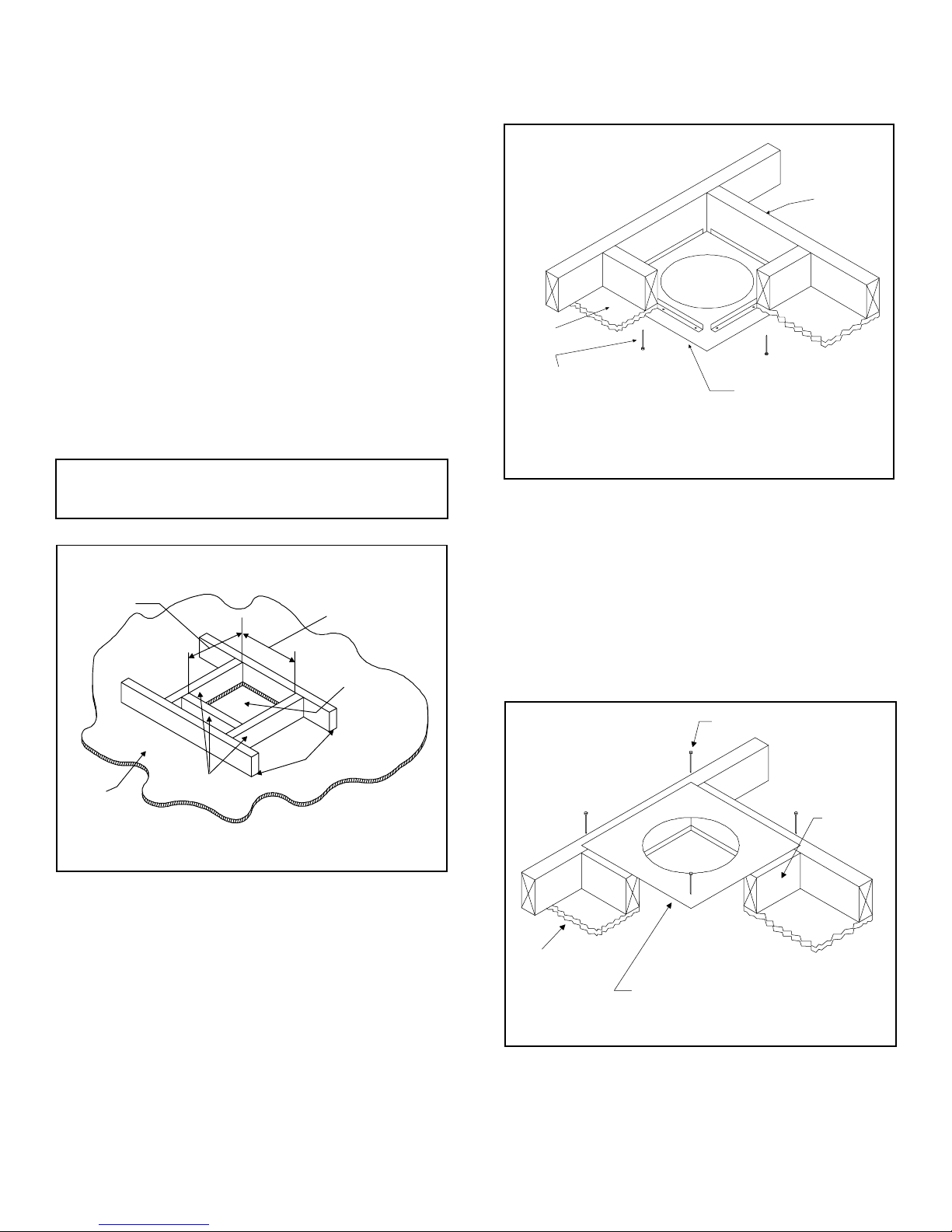
For Vertical Runs - One ceiling firestop is REQUIRED
at the hole in each ceiling through which the vent passes.
To install firestops for vertical runs that pass through ceilings:
Position a plumb bob directly over the center of the verti-
cal vent component.
If the area above the ceiling is NOT an attic, position and
secure the ceiling firestop on the ceiling side of the previously
cut and framed hole.
Mark the ceiling to establish the centerpoint of the vent.
Drill a hole or drive a nail through this centerpoint.
Check the floor above for any obstructions, such as wir-
ing or plumbing runs.
Reposition the fireplace and vent system, if necessary,
to accommodate the ceiling joists and/or obstructions.
CEILING
Cut an 10-inch x 10-inch (254mm x 254mm) hole through
the ceiling, using the centerpoint previously marked.
NAILS (4 REQUIRED)
Frame the hole with framing lumber the same size as the
ceiling joists.
Figure 22. Ceiling Firestop (Ceiling Side)
NOTE: There must be NO INSULATION or other
combustibles inside the framed firestop opening.
If the area above the ceiling IS an attic, position and secure
the firestop on top of the previously framed hole.
Figure 23 shows an attic installation. Keep insulation away
from the vent pipe at least 1 inch (25mm).
10" (254mm)
10" (254mm)
While it is not mandatory, it is strongly recommended that
an attic insulation shield be used whenever insulation can
come in contact with the vent pipe. Follow your local building
codes.
CHIMNEY
HOLE
JOIST
CEILING FIRESTOP
EXISTING CEILING
JOISTS
CEILING
NEW
FRAMING
MEMBERS
Figure 21. 10" x 10" Hole & New Framing Members
NAILS (4 REQUIRED)
RAFTER
CEILING
CEILING FIRESTOP
Figure 23. Attic Firestop
24
Page 21
C. Vent Termination
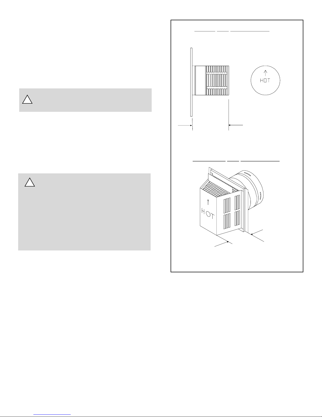
For Horizontal Terminations - To attach and secure
the termination to the last section of horizontal vent:
Rotate and interlock the ends as described at the begin-
ning of the Installing Vent Components section.
The termination kit should pass through the wall firestops
from the exterior of the building.
Adjust the termination cap to its final exterior position on
the building.
WARNING: THE TERMINATION CAP MUST BE
POSITIONED SO THAT THE ARROW IS POINT-
!
ING UP.
ROUND CAP TERMINATION
PERFORATION CANNOT BE
INSIDE THE WALL
For roundcap termination kits:
Use the exterior pipelock hole provided on the round
flange of the wall firestop to secure the vent pipe in
place.
For trapezoidal cap termination kits:
Using screws, secure the cap to the exterior wall
through the flanges built into the cap.
WARNING: THE BOTTOM OF THE VENT
!
TERMINATION CAP MUST BE A MINIMUM
OF 12 INCHES (305 MM) ABOVE GROUND LEVEL
(GRADE). THE TOP OF THE CAP MUST BE A MINIMUM OF 24 INCHES (690 MM) BELOW COMBUSTIBLE MATERIAL, SUCH AS A DECK, AND THE
SIDE OF THE CAP MUST BE A MINIMUM OF 6
INCHES (152 MM) AWAY FROM A PARALLEL OUTSIDE WALL. VENTING TERMINALS SHALL NOT
BE RECESSED INTO A WALL OR SIDING. SEE FIGURE 25 FOR VENT TERMINATION CLEARANCES.
7 1/2"
(191mm)
MINIMUM
TRAPEZOID CAP TERMINATION
7 1/4"
(184mm)
Figure 24. Round & Trapezoid Termination Caps
25
Page 22
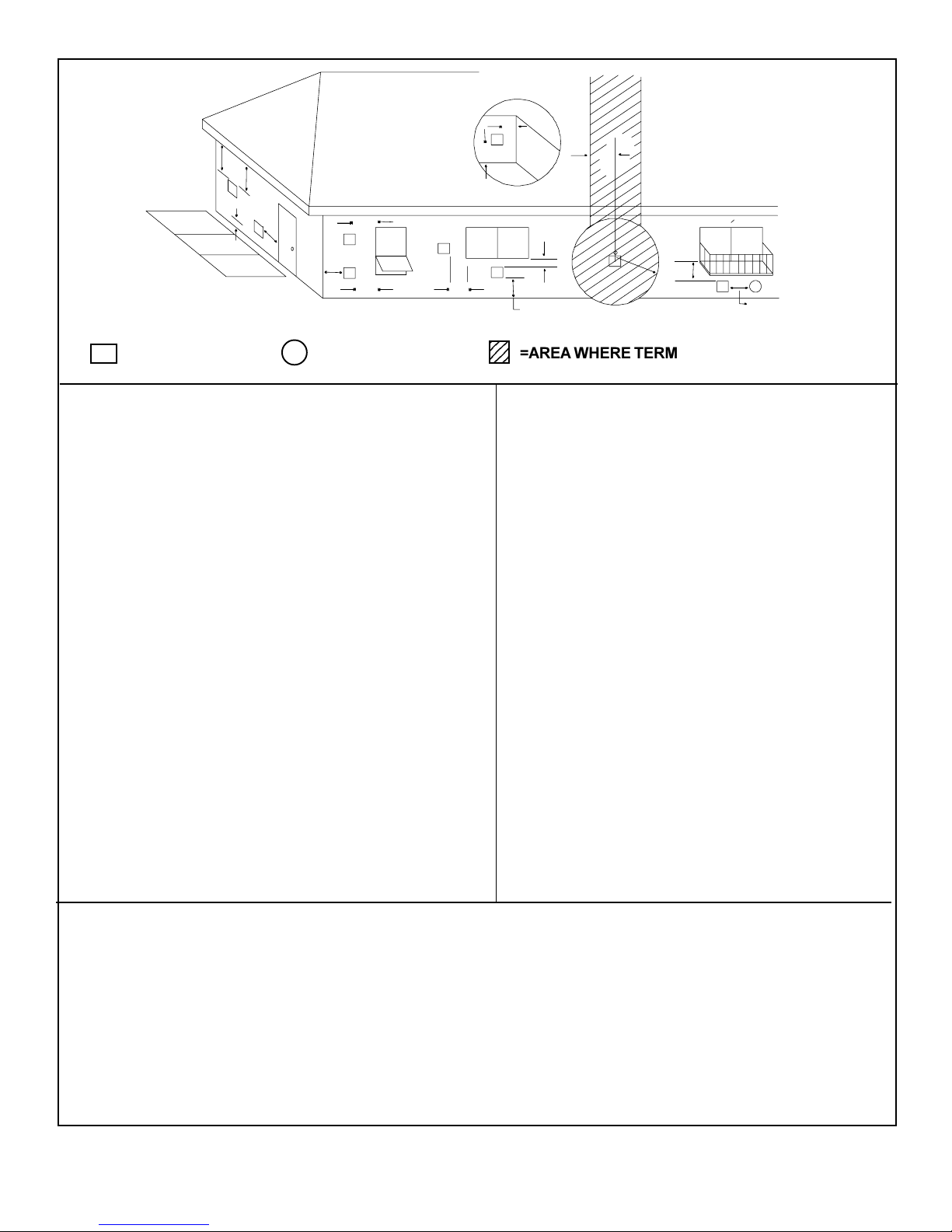
4
4
D
E
v
L
B
v
=VENT TERMINAL X =AIR SUPPLY INLET
V
C
v
F
v
B
openable
v
B
G
v
A
fixed closed
v
23
23
B
A
=AREA WHERE TERMINAL IS NOT PERMITTED
H
M
I
v
X
J or K
A = 12" .................... clearances above grade, veran-
da, porch, deck or balcony
B = 12" .................... clearances to window or door
that may be opened
C = 9" (U.S.A.)
12" (Canada) ..... clearance to permanently
closed window.
D = 24" .................... vertical clearance to ventilated
soffit located above the terminal within a horizontal distance
of 2 feet (60 cm) from the center-line of the terminal
E = 24" .................... clearance to unventilated soffit
F = 9" ..................... clearance to outside corner
G = 6" ...................... clearance to inside corner
H = 3 ft. (Canada) .... not to be installed above a gas
meter/regulator assembly within 3 feet (90cm) horizontally from
the center-line of the regulator
I = 3 ft. (U.S.A.)
6 ft. (Canada) ..... clearance to service regu-
lator vent outlet.
J = 9" (U.S.A.)
12" (Canada) ..... clearance to non-mechan-
ical air supply inlet to
building or the combustion
air inlet to any other appliance
K = 3 ft. (U.S.A.)
6 ft. (Canada) ..... clearance to a mechanical
air supply inlet
*L = 7 ft. ................... clearance above paved
sidewalk or a paved driveway located on public
property
**M = 24" .................... clearance under veranda,
porch, deck or balcony
* a vent shall not terminate directly above a sidewalk or paved driveway which is
located between two single family dwellings and serves both dwellings.
** only permitted if veranda, porch, deck or balcony is fully open on a minimum of
2 sides beneath the floor.
NOTE: Local Codes or Regulations may require different clearances.
Figure 25. Vent Termination Minimum Clearances
CAUTION: IF EXTERIOR WALLS ARE FINISHED WITH VINYL SIDING, IT IS NECESSARY TO INSTALL THE VINYL
PROTECTOR KIT TO THE TOP OF THE EXTERIOR FIRESTOP (FOR ALL ROUND TERMINATION CAPS).
26
Page 23
For Vertical Terminations - To locate the vent and
install the vent sections:
Locate and mark the vent centerpoint on the underside
of the roof, and drive a nail through the centerpoint.
Make the outline of the roof hole around the centerpoint
nail.
The size of the roof hole framing dimensions depend on the
pitch of the roof. There MUST BE a 1-inch (25.4mm) clearance from the vertical vent pipe to combustible materials.
Mark the roof hole accordingly.
Cover the opening of the installed vent pipes.
Cut and frame the roof hole.
To seal the roof hole, and to divert rain and snow from the
vent system:
Attach a flashing to the roof using nails, and use a non-
hardening mastic around the edges of the flashing base
where it meets the roof.
Attach a storm collar over the flashing joint to form a
water-tight seal. Place non-hardening mastic around the
joint, between the storm collar and the vertical pipe.
Slide the termination cap over the end of the vent pipe
and rotate the pipe clockwise 1/4 turn.
HORIZONTAL
OVERHANG
Use framing lumber the same size as the roof rafters
and install the frame securely. Flashing anchored to the
frame must withstand heavy winds.
Continue to install concentric vent sections up through
the roof hole (for inside vent installations) or up past the
roof line until you reach the appropriate distance above
the roof (for outside terminations).
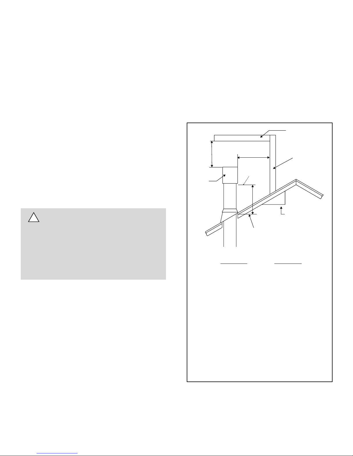
WARNING: MAJOR U.S. BUILDING CODES
!
SPECIFY MINIMUM CHIMNEY AND/OR
VENT HEIGHT ABOVE THE ROOF TOP. THESE MINIMUM HEIGHTS ARE NECESSARY IN THE INTEREST OF SAFETY. SEE THE FOLLOWING DIAGRAM
FOR MINIMUM HEIGHTS, PROVIDED THE TERMINATION CAP IS AT LEAST TWO (2) FEET FROM A
VERTICAL WALL AND 2-FEET BELOW A HORIZONTAL OVERHANG.
NOTE: This also pertains to vertical vent systems installed on the outside of the building.
2 FT.
MIN.
TERMINAT ION
CAP
2 FT. MIN.
LOWEST
DISCHARGE
OPENING
H (MIN.) - MINIMUM HEIGHT FROM ROOF
TO LOWEST DISCHARGE OPENING
X
12
ROOF PITCH
VERTICAL
WALL
IS X/ 12
Roof Pitch H (min.) ft.
flat to 6/12 1.0
6/12 to 7/12 1.25
over 7/12 to 8/12 1.5
over 8/12 to 9/12 2.0
over 9/12 to 10/12 2.5
over 10/12 to 11/12 3.25
over 11/12 to 12/12 4.0
over 12/12 to 14/12 5.0
over 14/12 to 16/12 6.0
over 16/12 to 18/12 7.0
over 18/12 to 20/12 7.5
over 20/12 to 21/12 8.0
Figure 26. Minimum Height from Roof to
Lowest Discharge Opening
27
Page 24

Step 4. Positioning, Leveling, and
Securing the Fireplace
The diagram below shows how to properly position, level,
and secure the fireplace.
PIER-38H V
Step 5. The Gas Control Systems
WARNING: THIS UNIT IS NOT FOR USE WITH
!
SOLID FUEL.
Two types of gas control systems are used with these models: Standing Pilot Ignition and Direct Spark Ignition (DSI).
Standing Pilot Ignition System
This system includes millivolt control valve, standing pilot,
thermopile/thermocouple flame sensor, and piezo ignitor.
WARNING: 110-120 VAC MUST NEVER BE
!
CONNECTED TO A CONTROL VALVE IN A
MILLIVOLT SYSTEM.
ST-38HV
Figure 27.
Proper Positioning, Leveling,
and Securing of a Fireplace
Place the fireplace into position.
Level the fireplace from side to side and from front to
back.
Shim the fireplace with non-combustible material, such
as sheet metal, as necessary.
Secure the fireplace to the framing by nailing or screwing.
Figure 28. Standing Pilot Ignition
Direct Spark Ignition (DSI) System
This system includes a 120VAC control valve, electronic
module and spark ignitor/flame sensor (see Figure 29).
WARNING: CONTINUOUS 110-120 VAC SERVICE
!
MUST BE WIRED DIRECTLY TO THE FIREPLACE
JUNCTION BOX IN A DSI SYSTEM.
WARNING: DIRECT VENT PROPANE MODELS
!
WITH DSI CONTROL SYSTEMS CANNOT BE
USED IN CANADA.
3/8”
(10mm)
Figure 29. Direct Spark Ignition
28
Page 25
Step 6. The Gas Supply Line
NOTE: Have the gas supply line installed in accordance
with local building codes by a qualified installer
approved and/or licensed as required by the locality.
NOTE: Before the first firing of the fireplace, the gas
supply line should be purged of any trapped air.
NOTE: Consult local building codes to properly size
the gas supply line leading to the 1/2 inch (13mm)
hook-up at the unit.
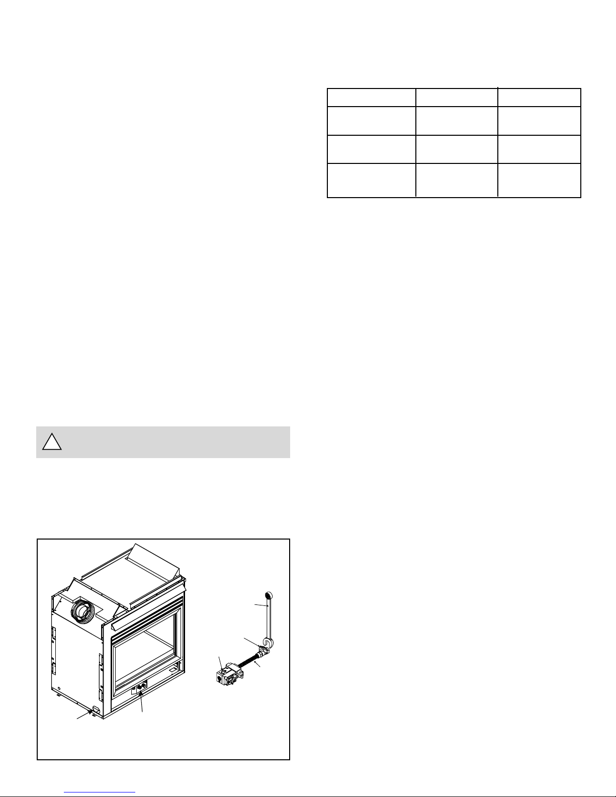
This gas fireplace is designed to accept a 1/2 inch (13mm)
gas supply line.
To install the gas supply line:
A listed (and State of Massachusetts approved) 1/2 inch
(13mm) tee-handle manual shut-off valve and a listed
flexible gas connector are connected to the 1/2 inch
(13mm) inlet of the control valve. NOTE: If substituting
for these components, please consult local codes for
compliance.
Locate the gas line access hole in the outer casing of
the fireplace.
The gap between the supply piping and gas access hole
can be plugged with non-combustible insulation to prevent cold air infiltration.
Open the fireplace lower grille, insert the gas supply line
through the gas line hole, and connect it to the shut-off
valve.
When attaching the pipe, support the control so that the
lines are not bent or torn.
After the gas line installation is complete, use a soap
solution to carefully check all gas connections for leaks.
Step 7. Gas Pressure Requirements
Pressure requirements for Heat-N-Glo gas fireplaces
are shown in the table below.
Pressure Natural Gas Propane
Minimum 5.0 inches 11.0 inches
Inlet Pressure w.c. w.c.
Maximum Inlet 14.0 inches 14.0 inches
Gas Pressure w.c. w.c.
Manifold 3.5 inches 10.0 inches
Pressure w.c. w.c.
A one-eighth (1/8) inch (3 mm) N.P.T. plugged tapping is
provided on the inlet and outlet side of the gas control for a
test gauge connection to measure the manifold pressure.
The fireplace and its individual shut-off valve must be
disconnected from the gas supply piping system during
any pressure testing of the system at test pressures in
excess of one-half (1/2) psig (3.5 kPa).
The fireplace must be isolated from the gas supply piping
system by closing its individual shut-off valve during any
pressure testing of the gas supply piping system at test
pressures equal to or less than one-half (1/2) psig (3.5 kPa).
WARNING: DO NOT USE AN OPEN FLAME
!
TO CHECK FOR GAS LEAKS.
At the gas line access hole, use insulation to re-pack
the space around the gas pipe.
Insert insulation from the outside of the fireplace and
pack the insulation tightly to totally seal between the
pipe and the outer casing.
USE A WRENCH ON
SHUT-OFF VALVE WHEN
TIGHTENING GAS LINE
MANUAL
SHUT-OFF VALVE
GAS VALVE
FLEX
CONNECTOR
GAS
LINE
ACCESS
CONTROL
VALVE
Figure 30. Gas Supply Line
29
Page 26
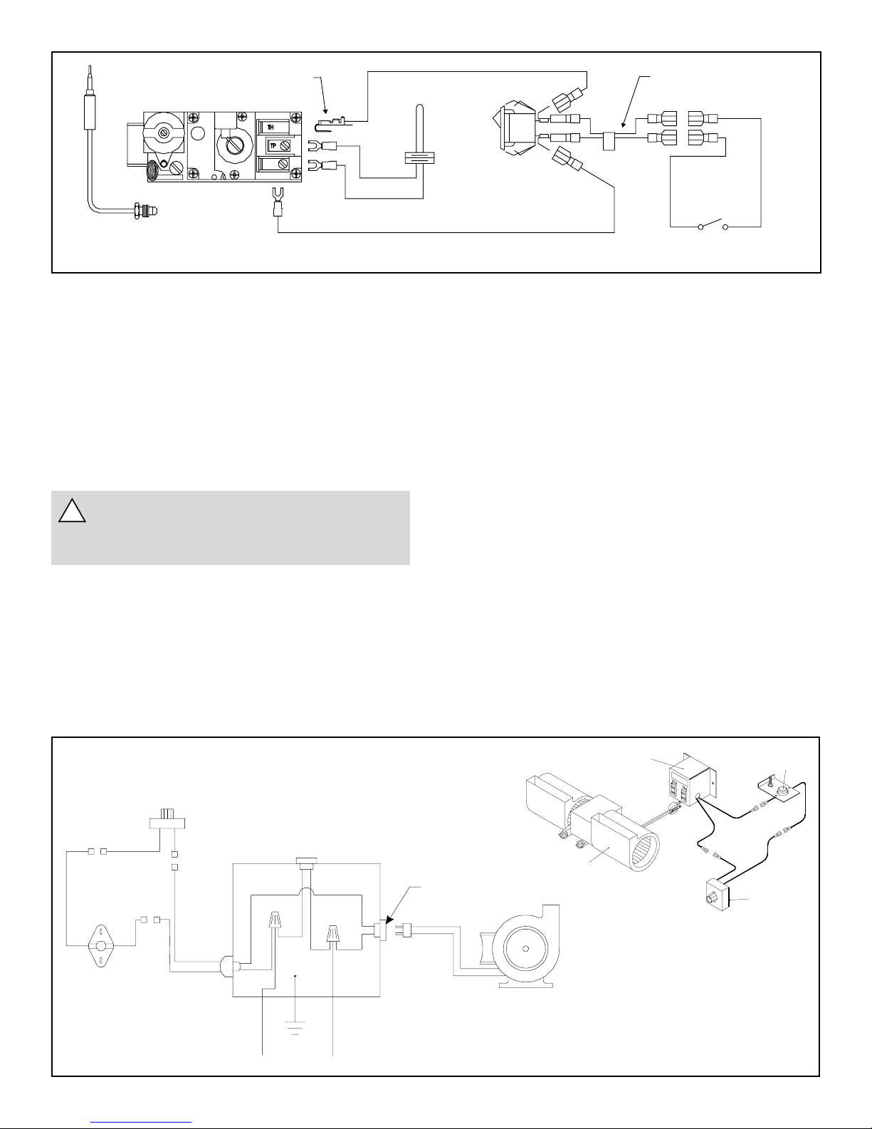
3/16” PIG GYBACK CONNECTOR
WHITE T2
GAS V ALU E
THERMOCOUPLE
RED T1
THERMOPILE
Figure 31. Standing Pilot Ignition Wiring Diagram
BLACK S2
ON
OFF
BLACK S1
ON/OFF
SWITCH
REMOTE SWITCH
PIGTAIL
OPTIONAL WALL SWITCH,
THERMOSTAT OR REMOTE
Step 8. Wiring the Fireplace
NOTE: Electrical wiring must be installed by a licensed
electrician.
CAUTION: DISCONNECT REMOTE CONTROLS IF YOU
ARE ABSENT FOR EXTENDED TIME PERIODS. THIS
WILL PREVENT ACCIDENTAL FIREPLACE OPERATION.
For Standing Pilot Ignition Wiring
Appliance Requirements
This appliance DOES NOT require 110-120 VAC to operate.
WARNING: DO NOT CONNECT 110-120 VAC
!
TO THE GAS CONTROL VALVE OR WALL
SWITCH OR THE APPLIANCE WILL MALFUNCTION
AND THE VALVE WILL BE DESTROYED.
Optional Accessories
Optional fan and remote control kits require that 110-120
VAC be wired to the factory installed junction box before
the fireplace is permanently installed.
Wall Switch
Position the wall switch in the desired position on a wall.
Run a maximum of 25 feet (7.8 m) continuous wire or less
length of 18 A.W.G. minimum wire and connect it to the
fireplace ON/OFF switch pigtails.
CAUTION: LABEL ALL WIRES PRIOR TO DISCONNECTION WHEN SERVICING CONTROLS. WIRING ERRORS
CAN CAUSE IMPROPER AND DANGEROUS OPERATION. VERIFY PROPER OPERATION AFTER SERVICING.
For Direct Spark Ignition (DSI) Wiring
Appliance Requirements
This appliance requires that 110-120 VAC be wired to the
factory installed junction box. Maintain correct polarity when
wiring the junction box.
Optional Accessories
Optional fan and remote control kits require that 110-120
VAC be wired to the fireplace junction box.
Wall Switch
Position the wall switch in the desired position on a wall.
Run a maximum of 25 feet (7.8 m) or less of 16 A.W.G.
minimum wire and connect it to the fireplace ON/OFF switch
pigtails.
CAUTION: LABEL ALL WIRES PRIOR TO DISCONNECTION WHEN SERVICING CONTROLS. WIRING ERRORS
CAN CAUSE IMPROPER AND DANGEROUS OPERATION.
VERIFY PROPER OPERATION AFTER SERVICING.
VARIABLE SPEED CONTROL
BLK
BLK
BLK
TEMPERATURE
SENSOR SWITCH
BLK
JUNCTION BOX
BLK
BLK
BLK
BLK
GROUND
Figure 32.
Fan Wiring Diagram
110-120 VAC
GRN
WHT
NOTE: IF ANY OF THE ORIGINAL WIRE
AS SUPPLIED WITH THE APPLIANCE
MUST BE REPLACED, IT MUST BE
REPLACED WITH TYPE 105 C RATED WIRE.
BLK
WHT
WHT
BLOWER RECEPTACLE
30
JUNCTION BOX
O
FAN
BLOWER
TEMPERATURE
SENSOR SWITCH
SPEED CONTROL
(RHEOSTAT)
Page 27
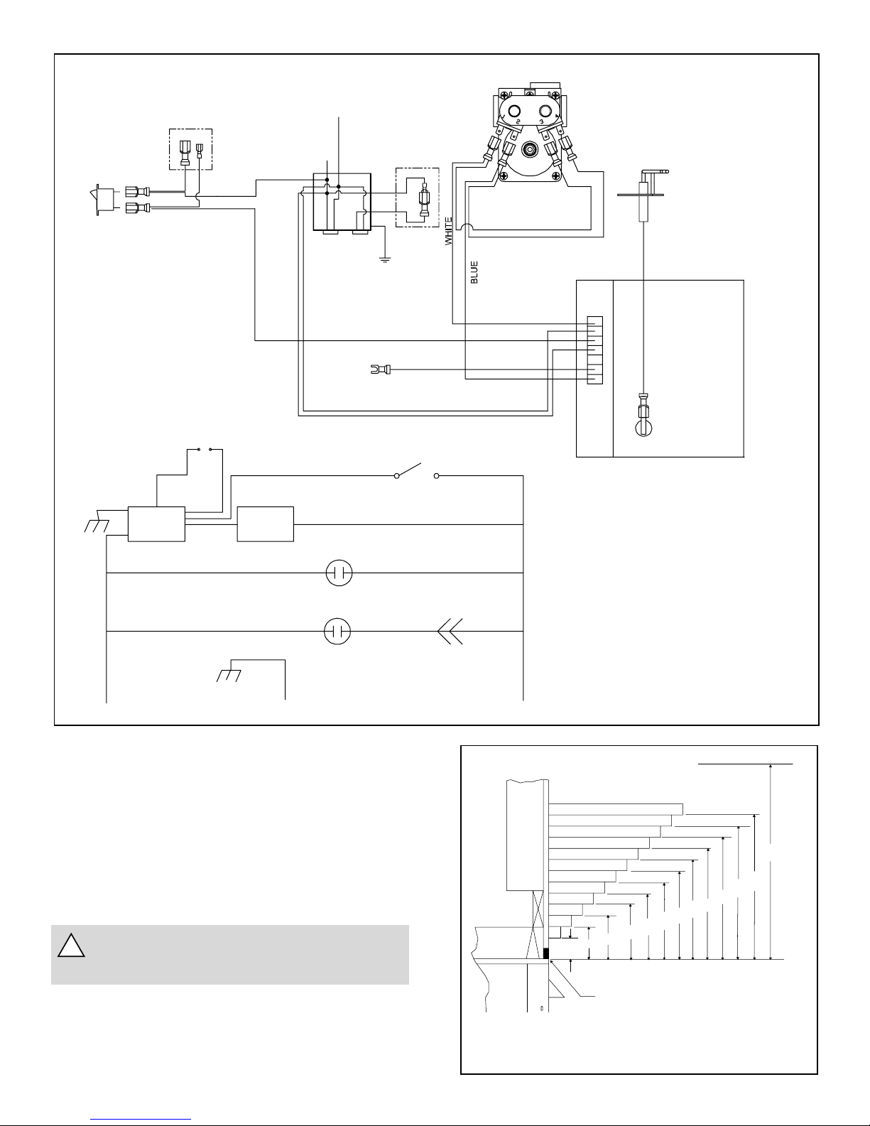
OPTIONAL REMOTE,
WALL SWITCH
OR THERMOSTAT
(ON CERTIFIED UNITS ON LY)
100-254A
JUNCTION
BOX
120 VAC
BLACK
L2
(NEUTRAL)
L1
(HOT)
OPTIONAL
FAN
SWITCHES
476-500
DSI CONTROL VALVE
459-591
IGNITOR
ON/OFF
FLAME SENSOR/SPARKER
IGNITION
MODULE
GAS
VALVE
120 VAC
POWER CORD
REMOTE OUTLET
REM
FAN
GROUND
TO
FIREPLACE
CHASSIS
GROUND
WHITE
BLACK
ON/OFF SWITCH
WHITE
YELLOW
GREEN
BLUE
WHITE
BLUE
E
G
N
A
R
O
501-592
DSI
MODULE
FAN OUTLET
NEUTRAL
Figure 33. Direct Spark Ignition (DSI) Wiring Diagram
Step 9. Finishing
Figure 34 shows the minimum vertical and corresponding
maximum horizontal dimensions of fireplace mantels or other
combustible projections above the top front edge of the
fireplace. See Figures 3 and 4 for other fireplace clearances.
Only non-combustible materials may be used to cover the
black fireplace front.
WARNING: WHEN FINISHING THE FIREPLACE,
!
NEVER OBSTRUCT OR MODIFY THE AIR INLET/OUTLET GRILLES IN ANY MANNER.
NOTE: Sheetrock can be placed on the top edge and sides
of the fireplace (see Figure 35).
CONNECTORS
Figure 34.
Minimum Vertical and Maximum Horizontal
Dimensions of Combustibles above Fireplace
HOTGROUND
CEILING
12"
11"
10"
9"
8"
7"
6"
5"
4"
3"
2"
1”
3”
2”
1”
TOP FRONT EDGE
OF FIREPLACE
6”
5”
4"
10”
9”
8”
7”
11”
36”
12”
31
Page 28
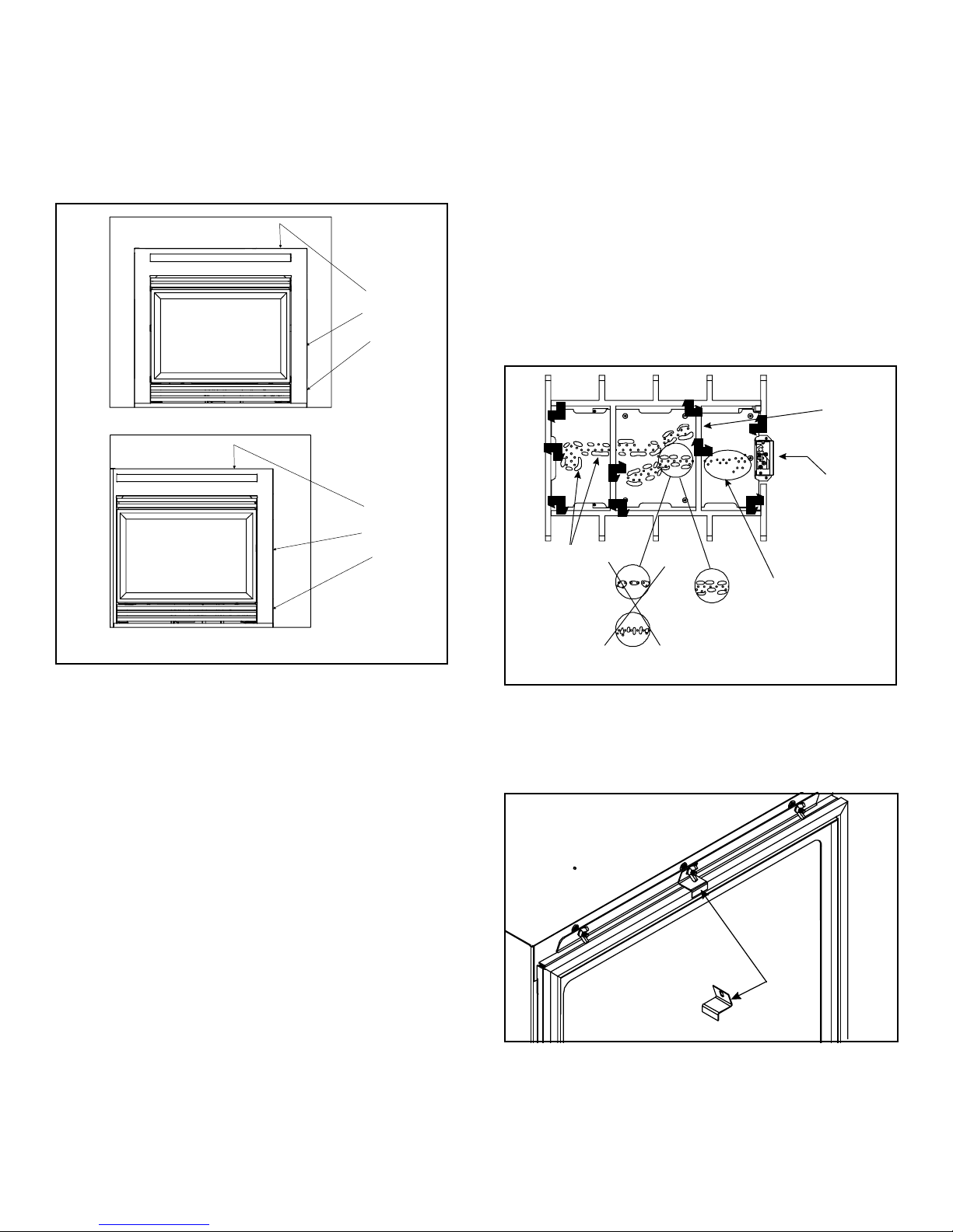
CAUTION: IF JOINTS BETWEEN THE FINISHED WALLS
AND THE FIREPLACE SURROUND (TOP AND SIDES)
ARE SEALED, A 300° F. MINIMUM SEALANT MATERIAL MUST BE USED. THESE JOINTS ARE NOT REQUIRED TO BE SEALED. ONLY NON-COMBUSTIBLE
MATERIAL (USING 300° F. MINIMUM ADHESIVE, IF
NEEDED) CAN BE APPLIED AS FACING TO THE FIREPLACE SURROUND. SEE THE DIAGRAM BELOW.
ST-38HV
TOP EDGE
SIDE EDGE
0” GAP
Placing the Ember Material
See two separate bags of ember material. The bag labeled
Golden Ember (GE-93) is flame colorant material. The bag
labeled Glowing Ember (050-721) is standard glowing ember
material. To place the ember material:
Remove the wing nuts, glass clips and spring clips around
the glass door. Remove the glass door.
Ember material is to be placed on burner with caution. Do
NOT place ember material over burner port holes. Place
only dime size pieces along outer edges of port trails (see
Figure 37). The bag is for (4) ember applications. Failure to
apply ember material as directed could result in poor lighting conditions and sooting problems. After placing ember
material sprinkle GE-93 on top of the burner. Save the remaining ember materials for use during fireplace servicing.
FIRST
GRATE BAR
Figure 35. Sealant Material
Hearth Extensions
A hearth extension may be desirable for aesthetic reasons.
However, ANSI or CAN/CGA testing standards do not require
hearth extensions for gas fireplace appliances.
Step 10. Installing Trim, Logs & Ember Material
Installing the Trim
Combustible materials may be brought up to the specified
clearances on the side and top front edges of the fireplace,
but MUST NEVER overlap onto the front face. The joints
between the finished wall and the fireplace top and sides
can only be sealed with a 300° F. (149° C) minimum sealant.
Install optional marble and brass trim surround kits as
desired. Marble, brass, brick, tile, or other non-combustible
materials can be used to cover up the gap between the
sheet rock and the fireplace.
Do not obstruct or modify the air inlet/outlet grilles. When
overlapping on both sides, leave enough space so that the
bottom grille can be raised and the trim door removed.
Positioning the Logs
The gas logs have been factory installed and should not
need to be positioned. After removing the stretch wrapping,
reinstall the logs and grate (see Figure 37). Make sure the
end of the grate with the incomplete cross bar is on the
pilot end of the firebox.
If sooting occurs, the logs might need to be repositioned
slightly to avoid excessive flame impingement.
PIER-38HV
TOP EDGE
SIDE EDGE
0” GAP
EMBER
MATERIAL
DO NOT PLACE EMBER
INCORRECT
EMBER PLACEMENT
CORRECT
EMBER
PLACEMENT
MATERIAL ON FIRST
SECTION OF PORTS
BETWEEN THE PILOT
ASSEMBL Y AND THE
FIRST GRATE BAR.
Figure 37. Placement of the Ember Material
Replace the wing nut, glass clips and spring clips.
If using the optional mesh doors, attach to fireplace glass
doors using the mesh clips provided in the manual bag.
See Figure 38.
Figure 38.
MESH
CLIP
CAUTION: IT IS STRONGLY RECOMMENDED THAT
TRIM DOORS WITH OPTIONAL MESH SCREENS BE INSTALLED ON PROPANE MODELS.
Replace the glass door and a front trim door on the unit.
Pull out and latch the glass clips into the groove on the
glass frame. Hand tighten the wing nuts.
32
PILOT
ASSEMBL Y
Page 29
GLASS SPECIFICATIONS:
LARGE SMALL GLASS
MODEL GLASS GLASS TYPE
PIER-38HV 34 X 20 20 X 20 TEMPERED
ST-38HV 34 X 20 N/A TEMPERED
Heat-N-Glo fireplaces manufactured with tempered glass may
be installed in hazardous locations such as bathtub
enclosures as defined by the CPSC. The tempered glass
has been tested and certified to the requirements of ANSI
Z97.1-1984 and CPSC 16 CFR 1202. (Safety Glazing
Certification Council SGCC # 1595 and 1597. Architectural
Testing, Inc. Reports 02-31919.01 and 02-31917.01.)
This statement is in compliance with CPSC 16 CFR Section
1201.5 Certification and labeling requirements which refers
to 15 USC 2063 stating Such certificate shall accompany
the product or shall otherwise be furnished to any distributor
or retailer to whom the product is delivered.
Some local building codes require the use of tempered glass
with permanent marking in such locations. Glass meeting
this requirement is available from the factory. Please contact
your dealer or distributor to order.
A small amount of air will be in the gas supply lines. When
first lighting the fireplace, it will take a few minutes for the
lines to purge themselves of this air. Once the purging is
complete, the fireplace will light and will operate normally.
Subsequent lightings of the fireplace will not require this
purging of air from the gas supply lines, unless the gas
valve has been turned to the OFF position, in which
case the air would have to be purged.
NOTE: The fireplace should be run 3 to 4 hours on the
initial start-up. Turn it off and let it cool completely. Remove
and clean the glass. Replace the glass and run the fireplace
for an additional 8 hours. This will help to cure the chemicals
used in the paint and logs.
Step 12. Lighting the Fireplace
Youve reviewed all safety warnings, youve checked the
fireplace for gas leaks, you know the vent system is
unobstructed, and youve checked for faulty components.
Now youre ready to light the fireplace.
Step 11. Before Lighting the Fireplace
Before lighting the fireplace, be sure to do the following:
Remove all paperwork from underneath the fireplace.
Review safety warnings and cautions
Read the Safety and Warning Information section at
the beginning of this Installers Guide.
Double-check for gas leaks
Before lighting the fireplace, double-check the unit for
possible gas leaks.
Double-check vent terminations and front grilles for
obstructions.
Before lighting the fireplace, double-check the unit for
possible obstructions that could be blocking the vent terminations or the front grilles.
Double-check for faulty components
Any component that is found to be faulty MUST BE re-
placed with an approved component. Tampering with the
fireplace components is DANGEROUS and voids all warranties.
WARNING: PLEASE REFER TO THE USERS
!
MANUAL FOR ALL CAUTIONS, SAFETY, AND
WARNING INFORMATION PERTAINING TO THE
LIGHTING AND OPERATION OF THE FIREPLACE.
After the Installation
LEAVE THIS INSTALLATION MANUAL WITH
!
THE APPLIANCE FOR FUTURE REFERENCE.
33
Page 30

Maintaining and Servicing
Your Fireplace
4
Fireplace Maintenance
Although the frequency of your fireplace servicing and maintenance will depend on use and the type of installation, you
should have a qualified service technician perform an appliance check-up at the beginning of each heating season.
See the table below for specific guidelines regarding each
fireplace maintenance task.
IMPORTANT: TURN OFF THE GAS BEFORE SERVICING
YOUR FIREPLACE.
Replacing old ember material
Frequency: Once annually, during the checkup.
By: Qualified service technician.
Task: Brush away loose ember material near the burner.
Replace old ember material with new dime-size and shape
pieces of Golden Ember (DE-93) and Glowing Ember (050-
721). New ember material should be placed alternately on
top of the burner - a layer of Golden Ember, a layer of
Glowing Ember, and so on. Save the remaining ember
material and repeat this procedure at your next servicing.
For more information, see Placing Ember Material.
Cleaning Burner and Controls
Frequency: Once annually.
By: Qualified service technician.
Task: Brush or vacuum the control compartment, fireplace
logs and burner areas surrounding the logs.
Checking Flame Patterns, Flame Height
Frequency: Periodically.
By: Qualified service technician/Home owner.
Task: Make a visual check of your fireplaces flame patterns.
Figure 39.
Burner Flame Patterns
Make sure the flames are steady - not lifting or floating.
See Figure 39. The flame sensor (DSI) or thermopile/
thermocouple (standing pilot) tips should be covered with
flame. See Figures 28 and 29.
Checking Vent System
Frequency: Before initial use and at least annually
thereafter, more frequently if possible.
By: Qualified service technician/Home owner.
Task: Inspect the external vent cap on a regular basis to
ensure that no debris is interfering with the flow of air. Inspect
entire vent system for proper function.
Cleaning Glass Door
Frequency: After the first 3 to 4 hours of use. As neces-
sary after initial cleaning.
By: Home owner.
Task: Remove and clean glass after the first 3 to 4 hours of
use. After the initial cleaning, clean as necessary, particularly after adding new ember (flame colorant) material. Film
deposits on the inside of the glass door should be cleaned
off using a household glass cleaner. NOTE: DO NOT handle
or attempt to clean the door when it is hot and DO NOT
use abrasive cleaners.
34
 Loading...