

Page 1

Log Set Assembly: LOGS-I35FB
LOG PLACEMENT INSTRUCTIONS
Models: ESCAPE-I35FB, ESCAPE-I35-C, ESCAPE-I35-F, ESCAPE-35-IFT
CAUTION: Logs are fragile, handle with care.
1
SRV2202-702
3
SRV2202-704
6
SRV2202-706
PILOT BRACKET
BURNER LEDGE
LIGHT TRAYS
1
3
5
6
LOG PINS
2
4
GRATE
SRV2202-701
BAR
2
4
SRV2202-703
5
SRV2202-705
BURNER LEDGE
GRATE TINES
Figure 1. Log Set Installed
FLAT SPOT
FOR LOG #5
LOG RESTS ON
PILOT BRACKET
Figure 2. Reference Points
1
REST LOG ON
BURNER LEDGE
Figure 3. Log #1
Log #1 (SRV2202-702): See Figure 2 for additional references. Position Log #1 as shown in Figure 3. Rest the left and
right ends of Log #1 on the burner ledge. The pilot bracket will support the center of the log. Pull the left end of the log
forward into position.
Heat & Glo • LOGS-I35FB Log Instructions • 2202-935 Rev. F • 5/18
1
Page 2

FLAT SPOT
FOR LOG#6
LOG MATES
WITH CORNER
OF BURNER
1
2
LOG HANGS OVER
ONTO BURNER TOP
Figure 4. Log #2
Log #2 (SRV2202-701): See Figure 2 for additional references. Position Log #2 as shown in Figure 4. Mate Log #2 with
the right corner of the burner as shown. Pull the log forward and to the left until it locks into position.
LOG CONTACTS LEFT
GRATE TINE
3
Figure 5. Log #3
Log #3 (SRV2202-704): See Figure 2 for additional reference details. Locate the log slot on the bottom right end of Log
#3. Mate the log slot with the left log pin. Rotate the left end of the log counterclockwise, until it contacts the grate tine.
Log #4 (SRV2202-703): See Figure 2 for additional reference details. Locate the log slot on the bottom left end of log #4.
Mate the log slot with the right log pin. Rotate the right end of the log clockwise, until it contacts the grate tine.
Figure 6. Log #4
LOG CONTACTS RIGHT
GRATE TINE
4
GLASS ROCK
Figure 7. Glass Rock in Place
Glass Rock (2201-853): Once Log #3 and Log #4 are installed, ll each light tray with the glass rock.
WARNING! Risk of Explosion! DO NOT place glass rock on the burner surface. DO NOT place glass rock directly over
burner ports. Improperly placed glass rock interferes with proper burner operation.
Heat & Glo • LOGS-I35FB Log Instructions • 2202-935 Rev. F • 5/182
Page 3
PLACE LOG
ON FLAT SPOT
5
GROOVE MATES
WITH GRATE BAR
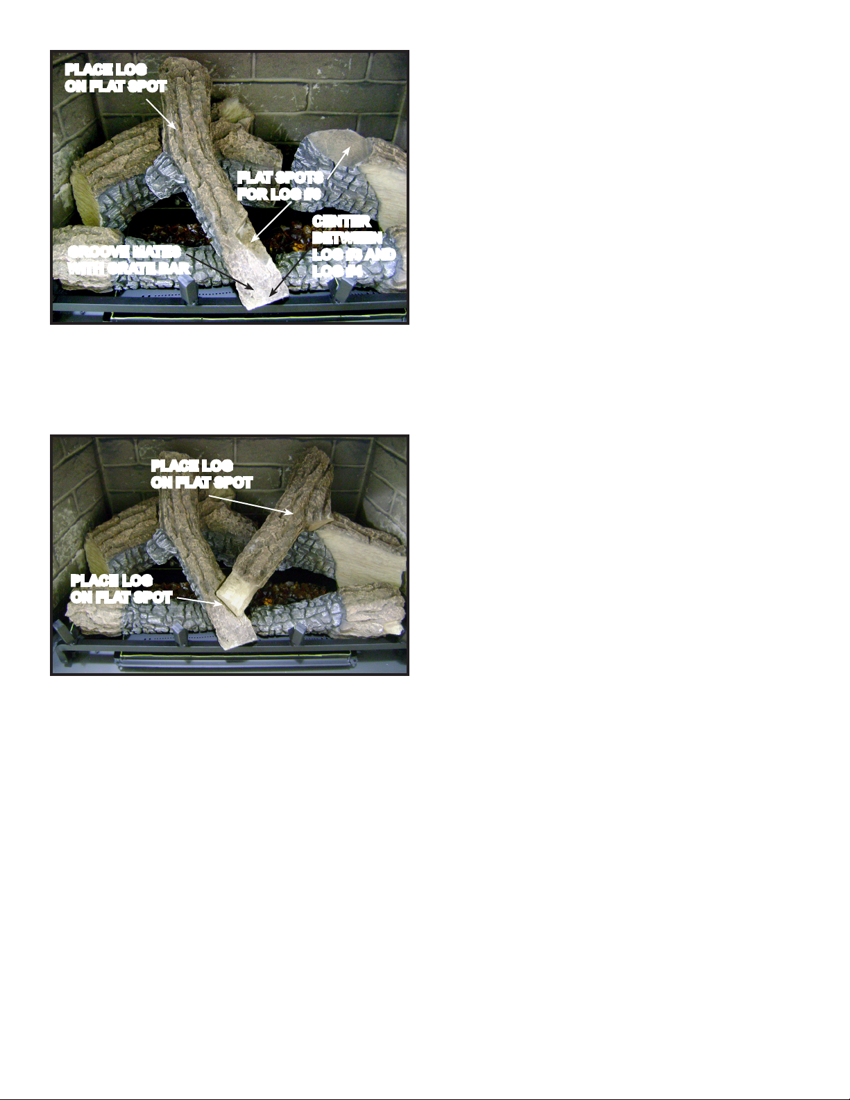
Figure 8. Place Log #5
Log #5 (SRV2202-705): See Figures 2 and 3 for additional references. Place the thick end of Log #5 on the at spot of
Log #1. Locate the groove on the thin end of the log. Mate the groove with the grate bar as shown above. Center the tip
of Log #5 between the ends of Log #3 and Log #4.
PLACE LOG
ON FLAT SPOT
FLAT SPOTS
FOR LOG #6
CENTER
BETWEEN
LOG #3 AND
LOG #4
6
PLACE LOG
ON FLAT SPOT
Figure 9. Place Log #6
Log #6 (SRV2202-706): See Figures 2 and 8 for additional references. Place the thick end of the log on the at spot of Log
#2. Place the thin end of Log #6 on the at spot of Log #5 as shown in Figure 9.
Heat & Glo • LOGS-I35FB Log Instructions • 2202-935 Rev. F • 5/18
3
 Loading...