

Page 1
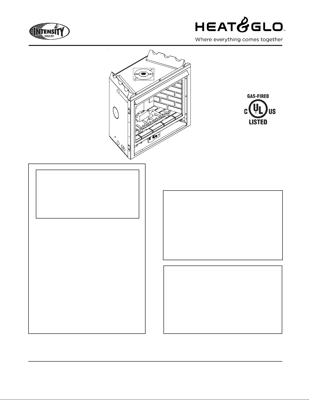
Models:
6000TRI-IPI
6000TRI-SP
WARNING: IF THE INFORMATION
IN THESE INSTRUCTIONS IS NOT
FOLLOWED EXACTL Y, A FIRE OR
EXPLOSION MAY RESULT CAUSING PROPERTY DAMAGE, PERSONAL INJURY, OR DEATH.
- Do not store or use gasoline or other flammable vapors and liquids in the vicinity of this
or any other appliance.
- What to do if you smell gas
• Do not try to light any appliance.
• Do not touch any electrical switch.
• Do not use any phone in your building.
• Immediately call your gas supplier from a
neighbor's phone. Follow the gas supplier's
instructions.
• If you cannot reach your gas supplier, call
the fire department.
- Installation and service must be performed by a
qualified installer, service agency, or the gas
supplier.
Installers Guide
Underwriters
Laboratories Listed
READ THIS MANUAL BEFORE INSTALLING OR
OPERATING THIS APPLIANCE. THIS INSTALLERS
GUIDE MUST BE LEFT WITH APPLIANCE FOR
FUTURE REFERENCE.
WARNING: IMPROPER INSTALLATION, ADJUSTMENT, ALTERATION,
SERVICE OR MAINTENANCE CAN
CAUSE INJURY OR PROPERTY DAMAGE. REFER TO THIS MANUAL. FOR
ASSIST ANCE OR ADDITIONAL INFORMATION CONSULT A QUALIFIED INST ALLER, SERVICE AGENCY , OR THE
GAS SUPPLIER.
1.This appliance may be installed in an aftermarket, permanently located, manufactured (mobile) home, where not prohibited
by local codes.
2. This appliance is only for use with the type
of gas indicated on the rating plate. This
appliance is not convertible for use with
other gases, unless a certified kit is used.
Printed in U.S.A. Copyright 2005,
Heat & Glo, a brand of Hearth & Home T echnologies Inc.
20802 Kensington Boulevard, Lakeville, MN 55044
This product is covered by one or more of the following patents: (United States) 4,112,913; 4,408,594; 4,422,426; 4,424,792; 4,520,791; 4,793,322;
4,852,548; 4,875,464; 5,000,162; 5,016,609; 5,076,254 5,191,877; 5,218,953; 5,328,356; 5,429,495; 5,452,708; 5,542,407; 5,613,487; (Australia)
543790; 586383; (Canada) 1,123,296; 1,297,746; 2,195,264; (Mexico) 97-0457; (New Zealand) 200265; or other U.S. and foreign patents pending.
Heat & Glo • 6000TRI-IPI, 6000TRI-SP • 385-901 Rev . F • 5/05
Please contact your Heat & Glo dealer with any
questions or concerns. For the number of your nearest
Heat & Glo dealer, please call 1-888-427-3973.
1
Page 2
SAFETY AND WARNING INFORMATION
READ and UNDERSTAND all instructions carefully
!
before starting the installation. FAILURE TO
FOLLOW these installation instructions may result
in a possible fire hazard and will void the warranty.
Prior to the first firing of the fireplace, READ the
!
Using Your Fireplace section of the Owners Guide.
DO NOT USE this appliance if any part has been
!
under water. Immediately CALL a qualified service
technician to inspect the unit and to replace any part
of the control system and any gas control which has
been under water.
THIS UNIT IS NOT FOR USE WITH SOLID FUEL.
!
Installation and repair should be PERFORMED by a
qualified service person. The appliance and venting
!
system should be INSPECTED before initial use
and at least annually by a professional service
person. More frequent cleaning may be required
due to excessive lint from carpeting, bedding
material, etc. It is IMPERATIVE that the unit’s
control compartment, burners, and circulating air
passageways
adequate combustion and ventilation air.
BE KEPT CLEAN to provide for
These units MUST use one of the vent systems
described in the Installing the Fireplace section of
!
the Installers Guide. NO OTHER vent systems or
components MAY BE USED.
This gas fireplace and vent assembly MUST be
!
vented directly to the outside and MUST NEVER be
attached to a chimney serving a separate solid fuel
burning appliance. Each gas appliance MUST USE
a separate vent system. Common vent systems are
PROHIBITED.
INSPECT the external vent cap on a regular basis to
!
make sure that no debris is interfering with the air
flow.
The glass door assembly MUST be in place and
!
sealed, and the trim door assembly MUST be in
place on the fireplace before the unit can be placed
into safe operation.
DO NOT OPERATE this appliance with the glass
!
door removed, cracked, or broken. Replacement of
the glass door should be performed by a licensed
or qualified service person. DO NOT strike or slam
the glass door.
Always KEEP the appliance clear and free from
!
combustible materials, gasoline, and other
flammable vapors and liquids.
NEVER OBSTRUCT the flow of combustion and
!
ventilation air. Keep the front of the appliance
CLEAR of all obstacles and materials for servicing
and proper operations.
Due to the high temperature, the appliance should
be LOCATED out of traffic areas and away from
!
furniture and draperies. Clothing or flammable
material SHOULD NOT BE PLACED on or near the
appliance.
Children and adults should be ALERTED to the
!
hazards of high surface temperature and should
STAY AWAY to avoid burns or clothing ignition.
Y oung children should be CAREFULL Y SUPERVISED
when they are in the same room as the appliance.
The glass door assembly SHALL ONLY be
!
replaced as a complete unit, as supplied by the gas
fireplace manufacturer. NO SUBSTITUTE material
may be used.
DO NOT USE abrasive cleaners on the glass door
!
assembly. DO NOT ATTEMPT to clean the glass
door when it is hot.
Turn off the gas before servicing this appliance. It is
recommended that a qualified service technician
!
perform an appliance check-up at the beginning of
each heating season.
Any safety screen or guard removed for servicing
!
must be replaced before operating this appliance.
DO NOT place furniture or any other combustible
!
household objects within 36 inches of the fireplace
front.
Heat & Glo • 6000TRI-IPI, 6000TRI-SP • 385-901 Rev . F • 5/052
Page 3

TABLE OF CONTENTS
Safety and Warning Information ................................................ 2
Î
Service Parts Lists ..................................................................... 4
Section 1: Approvals and Codes............................................... 8
Appliance Certification................................................................... 8
Installation Codes.......................................................................... 8
High Altitude Installations ............................................................... 8
Section 2: Getting Started ......................................................... 9
Introducing the Heat & Glo Gas Fireplaces................................... 9
Pre-installation Preparation........................................................... 9
Section 3: Installing the Fireplace ...........................................11
Constructing the Fireplace Chase ...............................................11
Step 1 Locating the Fireplace ..................................................11
Step 2 Framing the Fireplace.................................................. 12
Step 3 Installing the Vent System............................................ 14
A. Vent System Approvals........................................... 14
B. Installing V ent Components.................................... 21
C. Vent Termination .................................................... 24
Î
Step 4 Positioning, Leveling, and
Securing the Fireplace................................................. 26
Step 5 Installing the Optional Heat-Zone Kit............................ 27
Step 6 The Gas Control Systems ........................................... 27
Step 7 The Gas Supply Line ................................................... 28
Step 8 Gas Pressure Requirements ...................................... 28
Step 9 Wiring the Fireplace .................................................... 30
Step 10 Finishing ...................................................................... 31
Step 1 1 Installing Trim, Logs, and Ember Material.................... 32
Installing the Trim......................................................... 32
Positioning the Logs .................................................... 32
Shutter Settings........................................................... 32
Placing the Ember Material.......................................... 32
Glass Specifications.................................................... 32
Step 12 Before Lighting the Fireplace ....................................... 33
Step 13 Lighting the Fireplace .................................................. 34
After the Installation ..................................................................... 34
Section 4: Maintaining and Servicing Your Fireplace......... 34
Î
= Contains updated information.
Heat & Glo • 6000TRI-IPI, 6000TRI-SP • 385-901 Rev . F • 5/05
3
Page 4
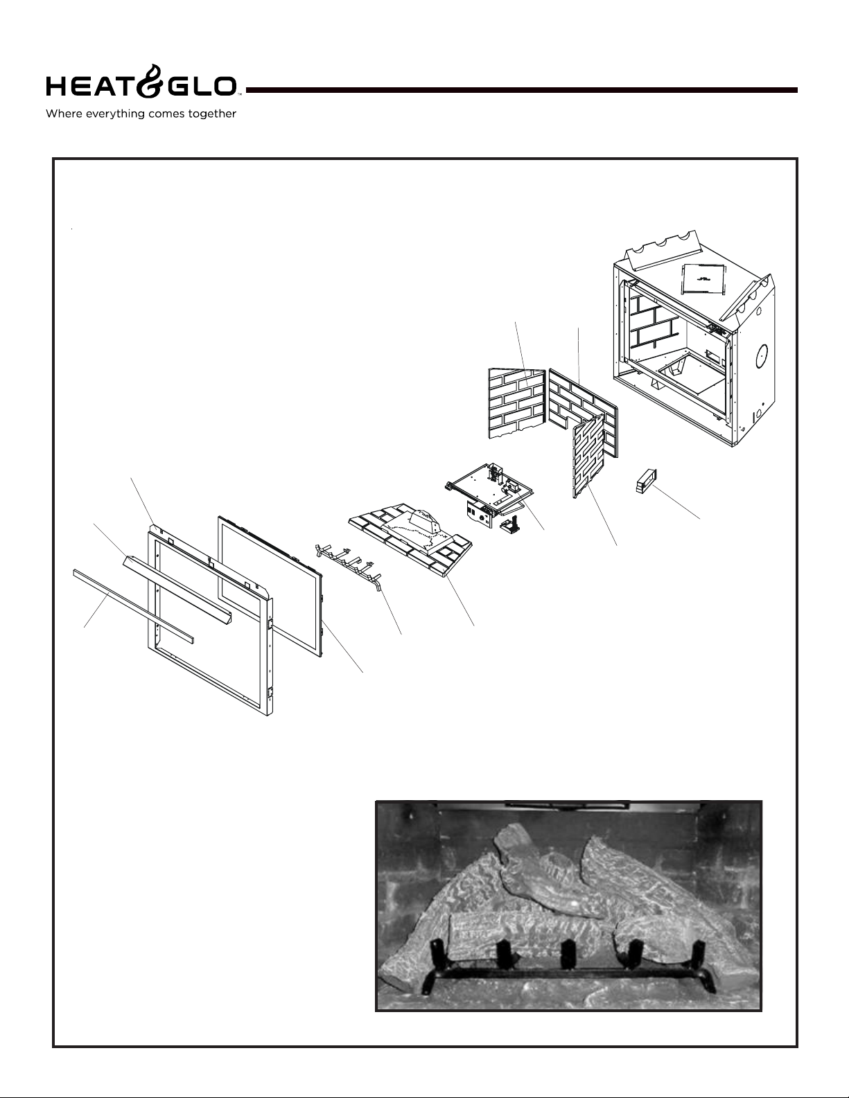
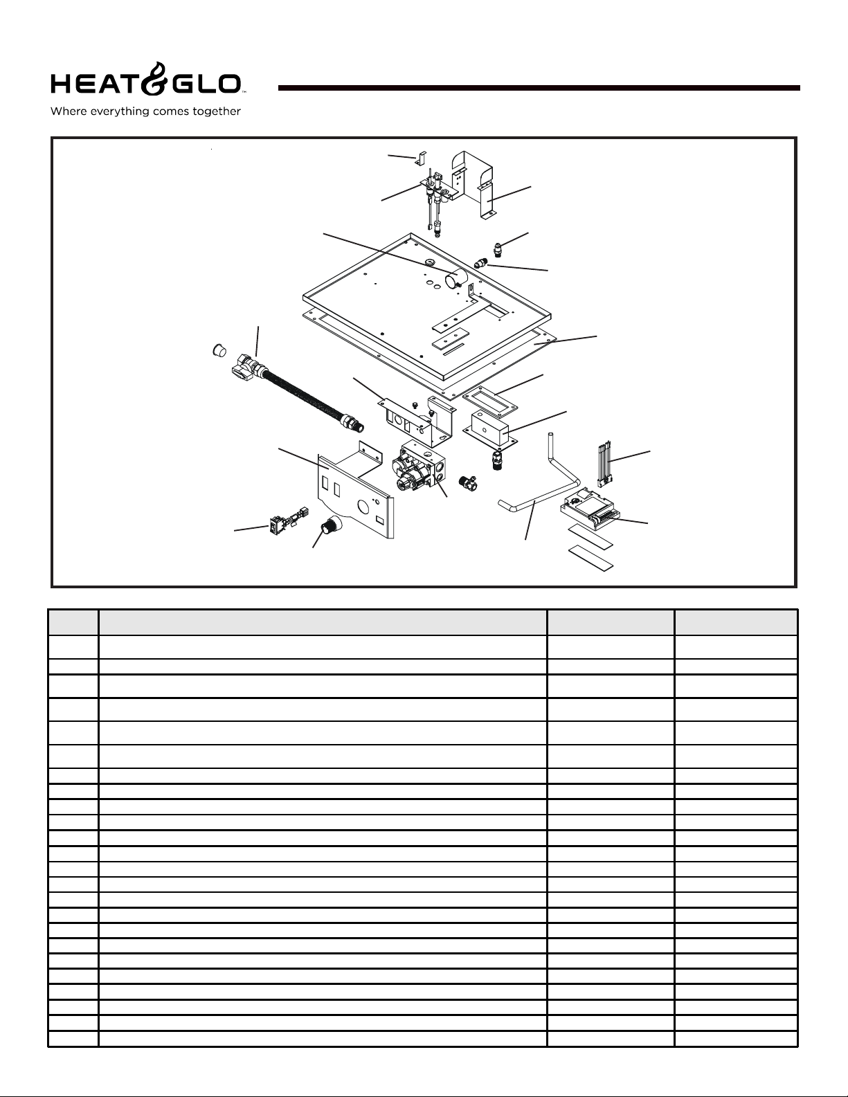
Service Parts
6000TRI-IPI, 6000TRI-SP
(NG , LP) Exploded Parts Diagram
(GN, PL) Vue éclatée des pièces
14
1
Beginning Manufacturing Date: 4-2001
Ending Manufacturing Date: ________
15
16
2
17
18
13
5
3
6 Log set assembly
4
7
12
10
11
Part number list on following page.
*
La liste des numéros de pièce se
*
trouve à la page suivante.
8
Heat & Glo • 6000TRI-IPI, 6000TRI-SP • 385-901 Rev . F • 5/054
9
Page 5
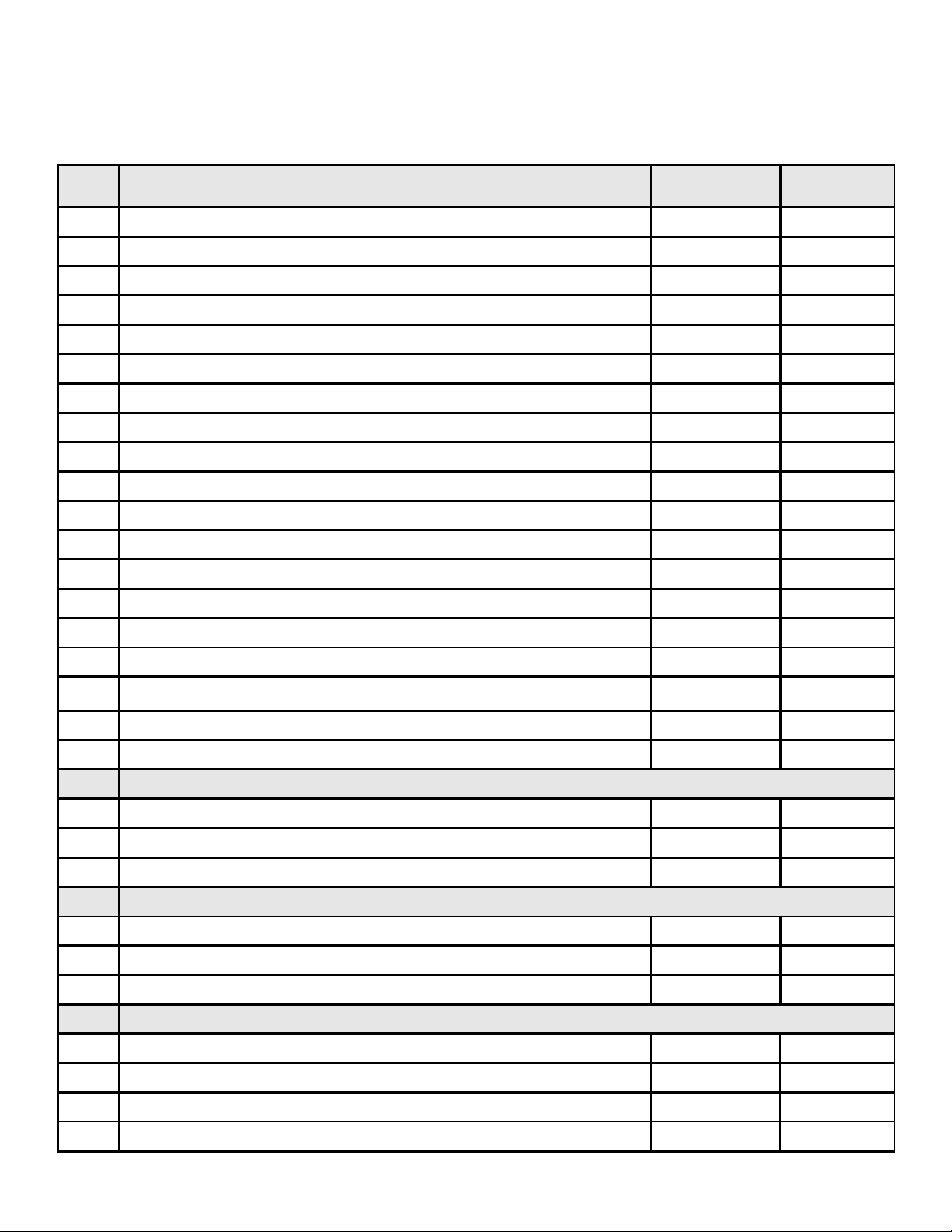
Service Parts List / Liste des pièces de rechange
6000TRI-SP, 6000TRI-IPI
IMPORTANT: THIS IS DATED INFORMA TION. The most current information is located on your dealers VIP site. When order-
ing, supply serial and model numbers to ensure correct service parts. / IMPORT ANT : L'information fournie dans cette brochure
n'est valide que pendant une courte période. Les sites VIP des distributeurs disposent des renseignements les plus récents.
Lors d'une commande, veuillez fournir les numéros de série et de modèles pour un remplacement adéquat des pièces.
ITEM /
PIÈCE
1 Surro und / Entoure nt
2 Hood / Hotte SRV60-143-BK
3 Glass Do o r Asse mbly / Porte en verre GLA-6TROC
4 B ur ner N G, L P / Br ûleur GN, PL
5 Log Grate / Grille de Bûche 385-360A
6 TRI Log Set Assembly / TRI Jeu de Bûches LOGS-6TRIC
7 Log 1 / Bûche 1 SRV2026-071
8 Log 2 / Bûche 2 SRV385-738
9 Log 3 / Bûche 3 SRV385-739
10 Log 4 / Bûche 4 SRV385-737
11 Log 5 / Bûche 5 SRV385-736
12 Log 6 / Bûche 6 SRV385-740
Wall R efrac tory Kit BRICK -6000-FB
13 Wall Refractory Kit - Right Wall SRV2027-372
COMMON PARTS / PIÈCES COMMUNES
SERIAL #
/ N° DE SÉRIE
PRE 002324002
POST 002324002
PRE 002324002
POST 002324002
PART NUMBER
/ N° DE PIÈCE
385-130
2026-108
385-339A
SRV2026-007A
14 Wall Refractory Kit - Left Wall SRV2027-371
15 Wall Refractory Kit - Back Wall SRV2027-370
16 Insulation Board / Conseil d'Isolation 385-401
Flue Restrictor / Restricteur de conduite de cheminée 385-128
Ve nt G ask et / J oint de Conduit 2026-114
INTERMITTENT PILOT IGNITION (IPI)* / IPI ALLUMAGE SEULEMENT
17 Junction Box / Boîtier de raccordement
NG Conversion - IPI Kit / Module de conversion GN - IPI NGK-6TRI-IPI
LP Conversion - IPI Kit / Module de conversion PL - IPI LPK-6TRI-IPI
STANDING PILOT IGNITION* / ALLUMAGE PAR VEILLEUSE
17 Junction Box / Boîtier de raccordement 4021-013
NG Conversion - IPI Kit / Module de conversion GN - IPI NGK-6TRI
LP Conversion - IPI Kit / Module de conversion PL - IPI LPK-6TRI
ACCESSORIES / ACCESSOIRES
Fan Kit / Module de ve ntilateur GFK-160A
Wall S witch K i t, O ff-whi te / Interrupte ur mura l, b la nc c rème WSK -2 1
PRE 002324002
POST 002324002
383-250A
4021-013
Í
Wall S witch K it, W hi te / Interrupte ur m ura l, blanc WSK -21- W
Trim Door Mesh / Écran porte de garniture MESH-6000
*Also see pages 6 and 7 for additional IPI and St anding Pilot Ignition service part numbers.
Heat & Glo • 6000TRI-IPI, 6000TRI-SP • 385-901 Rev . F • 5/05
5
Page 6
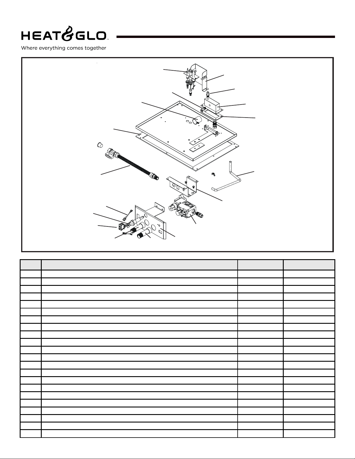
Service Parts
6000TRI-IPI
Intermittent Pilot Ignition
Valve Assembly
7
(NG , LP) Exploded Parts Diagram
(GN, PL) Vue éclatée des pièces
6
4
18
5
1
Beginning Manufacturing Date: 7-03
Ending Manufacturing Date: ______
17
16
15
14
13
12
11
8
2
3
ITE M /
PIÈCE
1 Control Panel / Tableau de commande avant
2 ON/OFF Rock er S wi tch / Interrup teur à bascule MA RC HE /A RRÊT 060-521A
3 F lame Control Knob / Flamber le Bouton de C ontrôle
4 P ilot Assembly NG / Module de veille use GN
4 P ilo t Ass em bly LP / Mo dule de veille use PL
5 Valve Bracket / Parenthèse de Valve
6 Ground Strap / Co urroie de Raison(Terre) 2025-512
7 F lex B all Valve Assembly / Fléchir l'Assemblée de S oupape de Balle 302-320A
8Valve NG / Valve GN 750-500
8 Valve LP / Valve PL 750-501
9 F lexible Gas Connector / Tuyau à gaz flexible 477-301A
10 Module / Module 593-592
11 Wire Assembly / Module de fil 593-590A
12 Manifold A ssembly / L'Assemblée diverse 385-301A
13 Manifold Gasket /Joint D iversifi é(Varié) 385-410
14 Valve Plate Gasket / Joint de P lat de Valve 385-402
15 Orifice Assembly NG (#43C ) / Assemblée d'Orifice GN (#43C) 582-843A
15 Orifice Assembly LP (#54C) / Assemblée d'Orifice PL (#54C) 582-854A
16 Orifice Assembly NG (#53C ) / Assemblée d'Orifice GN (#53C) 582-853A
16 Orifice Assembly LP (#66C) / Assemblée d'Orifice PL (#66C) 582-866A
17 Pilot Bracket / Parenthèse Pilote 385-164
18 Shutter Assembly / Assemblée d'Obturateur 319-316A
Battery Pack / Paquet de Batterie(Pile) 593-594A
3 Volt Transfo rmer / 3 Transformateur de Volt 593-593A
DESCRIPTION
9
PRE 002324002
POST 002324002
PRE 002324002
POST 002324002
PRE 002324002
POST 002324002
PRE 002324002
POST 002324002
PRE 002324002
POST 002324002
SERIAL #
/ N° DE S ÉRIE
10
PART N UMBE R
/ N° DE PIÈCE
N/A
2026-103
N/A
571-531
385-510A
4021-025
385-511A
4021-026
550-169
2025-101
Heat & Glo • 6000TRI-IPI, 6000TRI-SP • 385-901 Rev . F • 5/056
Page 7
Service Parts
6000TRI-SP
Standing Pilot Ignition
Valve Assembly
14
7
11
18
(NG , LP) Exploded Parts Diagram
(GN, PL) Vue éclatée des pièces
4
15
6
Beginning Manufacturing Date: 7-03
Ending Manufacturing Date: ______
17
16
12
13
9
5
2
10
ITEM /
PIÈCE
1 Control Panel / Tableau de comma nde avant 385-154
2 ON/OFF Ro cke r Swi tch / Int e r rupt eur à b a s cule MARC HE/ARRÊT 060-521A
3 F lame Control Knob / F lamber le Bouton de Contrôle 571-531
4 P i lot Assembly NG / Module de veilleuse GN 485-510A
4 P i lot Assembly LP / Module de veilleuse PL 485-511A
5 Valve Bracket / Parenthèse d e Valve 550-169
6 Shutter Assembly / Assemblée d'Obturateur 319-316A
7 F lex Ball Valve Assembly / Fléchir l'Assemblée de Soupap e de B alle 302-320A
8 Valve NG / Valve GN 060-522
8 Valve LP / Valve PL 060-523
9 F lexible Gas Connector / Tuyau à gaz fle xible 477-301A
10 P i lot Control K nob / Piloter le B outon de Contrôle 571-530
11 Wi re A ss emb ly / Module de fil 049-552A
12 Manifold Assembly / L'Assemblée diverse 385-301A
13 Manifold Gasket /Joint Diversifié(Varié) 385-410
14 Valve Plate Gasket / Joint de Plat de Valve 385-402
15 Orifice Assembly NG (#43C) / Assemblée d'Orifice GN (#43C) 582-843A
15 Orifice Assembly LP (#54C) / Assemblée d'Orifi ce PL (#54C) 582-854A
16 Orifice Assembly NG (#53C) / Assemblée d'Orifice GN (#53C) 582-853A
16 Orifice Assembly LP (#66C) / Assemblée d'Orifi ce PL (#66C) 582-866A
17 Pilot Bracket / Parenthèse Pilote 385-164
18 Piezo Ignitor / Allumeu r piézo 291-513
DESCRIPTION
3
1
8
SERIAL #
/ N° DE SÉRIE
PART NUMBER
/ N° DE PIÈCE
Heat & Glo • 6000TRI-IPI, 6000TRI-SP • 385-901 Rev . F • 5/05
7
Page 8
1
Approvals and
Codes
Appliance Certification
The Heat & Glo fireplace models discussed in this Installers
Guide have been tested to certification standards and listed
by the applicable laboratories.
Certification
MODELS: 6000TRI-IPI, 6000TRI-SP
LABORA TORY : Underwriters Laboratories
TYPE: Direct Vent Gas Fireplace Heater
ST ANDARD: ANSI Z21.88-2000•CSA2.33-M98•UL307B
Installation Codes
The fireplace installation must conform to local codes. Before
installing the fireplace, consult the local building code
agency to ensure that you are in compliance with all
applicable codes, including permits and inspections.
In the absence of local codes, the fireplace installation must
conform to the National Fuel Gas Code ANSI Z223.1 (in
the United St ates) or the CAN/CGA-B149 Installation Codes
(in Canada). The appliance must be electrically grounded
in accordance with local codes or, in the absence of local
codes with the National Electric Code ANSI/NFPA No. 70
(in the United St ates), or to the CSA C22.1 Canadian Electric
Code (in Canada).
High Altitude Installations
U.L. Listed gas appliances are tested and approved without
requiring changes for elevations from 0 to 2,000 feet in the
U. S. A. and in Canada.
When installing this appliance at an elevation above 2,000
feet, it may be necessary to decrease the input rating by
changing the existing burner orifice to a smaller size. Input
rate should be reduced by 4% for each 1000 feet above a
2000 foot elevation in the U.S.A. or 10% for elevations
between 2000 and 4500 feet in Canada. If the heating value
of the gas has been reduced, these rules do not apply . To
identify the proper orifice size, check with the local gas
utility.
If installing this appliance at an elevation above 4,500 feet
(in Canada), check with local authorities.
These models may be installed in a bedroom or bed-sitting
room in the U.S.A. and Canada.
Heat & Glo Quality Systems
registered by SGS ICS
Heat & Glo • 6000TRI-IPI, 6000TRI-SP • 385-901 Rev . F • 5/058
Page 9

2
Getting Started
Introducing the Heat & Glo Gas Fireplaces
Heat & Glo direct vent gas fireplaces are designed to operate with all combustion air siphoned from outside of the
building and all exhaust gases expelled to the outside.
The information contained in this Installers Guide, unless
noted otherwise, applies to all models and gas control
systems. Gas fireplace diagrams, including the dimensions,
are shown in this section.
Pre-install Preparation
This gas fireplace and its components are tested and safe
when installed in accordance with this Installers Guide.
Report to your dealer any parts damaged in shipment,
particularly the condition of the glass. Do not install any
unit with damaged, incomplete, or substitute parts.
The vent system components and trim doors are shipped
in separate packages. The gas logs may be packaged
separately and must be field installed.
Read all of the instructions before starting the
installation. Follow these instructions carefully during
the installation to ensure maximum safety and benefit.
Failure to follow these instructions will void the
owner’s warranty and may present a fire hazard.
The Heat & Glo Warranty will be voided by , and Heat & Glo
disclaims any responsibility for, the following actions:
• Installation of any damaged fireplace or vent system
component.
• Modification of the fireplace or direct vent system.
• Installation other than as instructed by Heat & Glo.
• Improper positioning of the gas logs or the glass door.
• Installation and/or use of any component part not manufactured and approved by Heat & Glo, not withstanding
any independent testing laboratory or other party approval
of such component part or accessory .
ANY SUCH ACTION MAY POSSIBLY CAUSE A FIRE
HAZARD.
When planning a fireplace installation, it’s necessary to
determine:
• Where the unit is to be installed.
• The vent system configuration to be used.
• Gas supply piping.
• Electrical wiring.
• Framing and finishing details.
• Whether optional accessories—devices such as a fan,
wall switch, or remote control—are desired.
If the fireplace is to be installed on carpeting or tile, or on
any combustible material other than wood flooring, the
fireplace should be installed on a metal or wood panel that
extends the full width and depth of the fireplace.
Heat & Glo • 6000TRI-IPI, 6000TRI-SP • 385-901 Rev . F • 5/05
9
Page 10
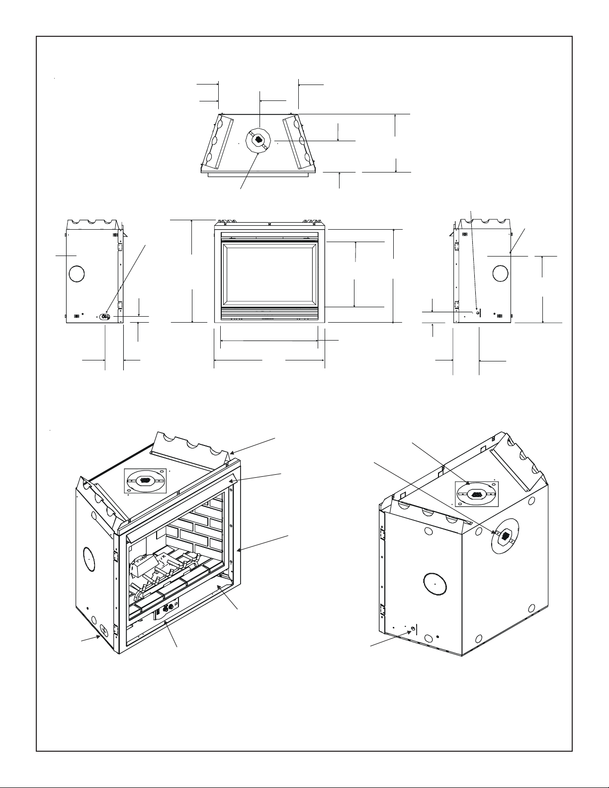
V
14 1/4
[362mm]
28 1/2 [724mm]
21 1/2 [548mm]
GAS LINE
2 1/8
[55mm]
6 7/8 [174mm]
ACCESS
38
[965mm]
8 [203mm]
VENT COLLARS
41 1/8
[1044mm]
TOP STANDOFFS
REAR VENT COLLARS
HOOD
11 5/8 [297mm]
25 1/4
[642mm]
36 1/8
[916mm]
34 5/8
[879mm]
3 1/2
[90mm]
TOP VENT COLLARS
ELECTRICAL
ACCESS
8 [203mm]
COLLARS
12 3/4
[323mm]
ENT
26 7/8
[682mm]
TRIM
DOOR
RATING PLATE
GAS
AND LABELS
ELECTRICAL
ACCESS
GAS
LINE
ACCESS
CONTROLS
Figure 1. Diagram of the 6000TRI-IPI, 6000TRI-SP
Heat & Glo • 6000TRI-IPI, 6000TRI-SP • 385-901 Rev . F • 5/0510
Page 11
Installing the Fireplace
3
Constructing the Fireplace Chase
A chase is a vertical box-like structure built to enclose the
gas fireplace and/or its vent system. V ertical vents that run
on the outside of a building may be, but are not required to
be, installed inside a chase.
CAUTION: TREA TMENT OF FIRESTOP SPACERS AND
CONSTRUCTION OF THE CHASE MA Y V ARY WITH THE
TYPE OF BUILDING. THESE INSTRUCTIONS ARE NOT
SUBSTITUTES FOR THE REQUIREMENTS OF LOCAL
BUILDING CODES. THEREFORE, YOUR LOCAL BUILDING CODES MUST BE CHECKED TO DETERMINE THE
REQUIREMENTS FOR THESE STEPS.
Factory-built fireplace chases should be constructed in the
manner of all outside walls of the home to prevent cold air
drafting problems. The chase should not break the outside
building envelope in any manner.
This means that the walls, ceiling, base plate and cantilever floor of the chase should be insulated. Vapor and air
infiltration barriers should be installed in the chase as per
regional codes for the rest of the home. Additionally , Heat &
Glo recommends that the inside surfaces be sheetrocked
and taped for maximum air tightness.
T o further prevent drafts, the firestop s should be caulked to
seal gaps. Gas line holes and other openings should be
caulked or stuffed with insulation. If the unit is being installed on a cement slab, we recommend that a layer of
plywood be placed underneath to prevent conducting cold
up into the room. Be sure to include spark arrestors for
woodburning units if they are required.
THE CHASE SHOULD BE CONSTRUCTED SO THAT ALL
CLEARANCES TO THE FIREPLACE ARE MAINT AINED
AS SPECIFIED WITHIN THIS INST ALLERS GUIDE.
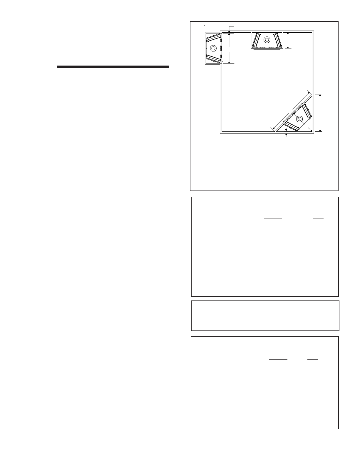
Step 1. Locating the Fireplace
The following diagram shows space and clearance requirements for locating a fireplace within a room.
Clearance Requirements
The top, back, and sides of the fireplace are defined by
stand-offs. The minimum clearance to a perpendicular wall
extending past the face of the fireplace is one inch (25 mm).
The back of the fireplace may be recessed 21 1/2 inches
(546 mm) into combustible construction.
1” MIN. (25mm)
B
A
E
C
1/2” MIN. (13mm)
ABC DE
42” 22” 36” 51” 72”
Note* 42” 22” 40” 57” 80”
*If venting with (2) 900 elbows off rear of unit
the dimensions C, D, and E, will change.
Figure 2. Fireplace Dimensions, Locations,
and Space Requirements
Minimum Clearances
from the Fireplace to Combustible Materials
Inches mm
Glass Front........................ 36 .................... 91 4
Floor ................................... 0 ....................... 0
Rear ...................................1/2..................... 13
Sides .................................1/2..................... 13
Surround Sides*.................. 0 ....................... 0
To p................................... 3 1/2 ................... 89
Ceiling**............................. 31 .................... 787
* See Figure 3.
**The clearance to the ceiling is measured from the top
of the unit, excluding the standoffs (see Figure 39).
The distance from the unit to combustible construction
is to be measured from the unit outer wrap surface to
the combustible construction, NOT from the screw heads
that secure the unit together.
Minimum Clearances
from the Vent Pipe to Combustible Materials
Inches mm
Vertical Sections. ............. 1 ................ 25
Horizontal Sections
Top..................................... 3 ................ 75
Bottom ............................... 1 ................ 25
Sides ................................. 1 ................ 25
At Wall Firestops
Top..................................... 3 ................ 75
Bottom ............................... 1 ................ 25
Sides ................................. 1 ................ 25
D
For minimum clearances, see the direct vent termination
clearance diagrams on pages 24 and 25 in this manual.
Heat & Glo • 6000TRI-IPI, 6000TRI-SP • 385-901 Rev . F • 5/05
11
Page 12

Step 2. Framing the Fireplace
Fireplace framing can be built before or after the fireplace is
set in place. Framing should be positioned to accommodate wall coverings and fireplace facing material. The diagram below shows framing reference dimensions.
Framing should be
constructed of 2 X 4
lumber or heavier.
B
C
A
A.............. 42”*
B..........38 1/2”
C................ 22”
D..........42 3/4”
E. .........27 7/8”
CAUTION: MEASURE FIREPLACE DIMENSIONS AND
VERIFY FRAMING METHODS AND WALL COVERING
DET AILS BEFORE FRAMING .
Noncombustible zone is defined
by 3” above the elbow for the
entire width and depth (behind
the front header) of the firebox.
WALL
STUD
3 1/2”
3
”
E D
Shows center of 10” x 12” vent framing
holes for top and rear venting. The center
of the hole is one (1) inch (25.4mm) above
the center of the horizontal vent pipe.
Figure 3. Framing Dimensions
Heat & Glo • 6000TRI-IPI, 6000TRI-SP • 385-901 Rev . F • 5/0512
1/2” CLEARANCE
FROM BOTH SIDES
OF FIREPLACE
TO COMBUSTIBLE
FRAMING
MEMBER
1/2” CLEARANCE FROM BACK OF FIREPLACE TO COMBUSTIBLE
0” CLEARANCE
0” CLEARANCE TO
FRAMING MEMBER
Page 13

12-3/16
MAX.
DVP12
12
MIN.
6
4
DVP4
DVP6
14-1/4
2
24
9-7/8
DVP12A
10-1/4
DVP45
45.0
36
48
O
DVP24
7-1/4
11-1/4
1-1/4 TYP
DVP36
DVP48
1/2 TYP
12-9/16
V
D
P
9
8-9/16
S
0
T
NOTE: PIPES OVERLAP 1-1/4 INCHES A T EACH JOINT.
Figure 4. DVP-Series Direct Vent Component Specifications (5-inch inner pipe / 8-inch outer pipe)
Heat & Glo • 6000TRI-IPI, 6000TRI-SP • 385-901 Rev . F • 5/05
13
Page 14

Step 3. Installing the Vent System
A. Vent System Approvals
These models are approved to use DVP-series direct vent
pipe components and terminations (see Figures 4 and 5).
Approved vent system components are labeled for identification. This pipe is tested and listed as an approved component of the fireplace. The pipe is tested to be run inside
an enclosed wall. There is no requirement for inspection
openings at each joint within the wall. There is no required
pitch for horizontal vent runs. NO OTHER VENTING SYS-
TEMS OR COMPONENTS MA Y BE USED.
Detailed installation instructions are included with each vent
termination kit and should be used in conjunction with this
Installers Guide.
The flame and ember appearance may vary based on the type
of fuel burned and the venting configuration used.
VERTICAL
TERMINATION
Identifying Vent Component s
The vent systems installed on this gas fireplace may include one, two, or three 90° elbow assemblies. The relationships of vertical rise to horizontal run in vent configurations using 90° elbows MUST BE strictly adhered to. The
rise to run relationships are shown in the venting drawings
and tables. Refer to the diagrams on the next several pages.
NOTE: Two 45° elbows may be used in place of one
90° elbow. Rise to run ratios in the vent system must
be followed if 45° elbows are used.
This model has vent starting collars on both the top and the
back of the unit. Depending upon the installation, decide
which ONE set of starting collars will be used to attach the
vent system. The starting collar sealing cap must remain
on the starting collar NOT used.
STORM COLLAR
T erminations Kits
(For use on IPI units only)
ROOF FLASHING
HORIZONTAL
TERMINATION
PIPE LENGTH
WALL FIRESTOP
90 DEGREE
ELBOW
DVP-TVPVK-80
CEILING
FIRESTOP
DVP-TRAP
SERIES
DVP-TVHW
DVP-TB1
(Required to have a minimum of 3
feet of vertical in the vent system)
Figure 5. Vent System Component s and Termination Kits
Heat & Glo • 6000TRI-IPI, 6000TRI-SP • 385-901 Rev . F • 5/0514
Page 15

STRAIGHT UP
VERTICAL VENTING
V (FT.)
40' MAX. (12.4 M)
NOTE: On vertical venting
configurations over 10 feet
install the flue restrictor
(385-128) included in the
manual bag assembly . See
flue restrictor instructions.
Flue Restrictor Instructions
1. Remove Exhaust Shield using a 1/4” nut driver by
removing the four screws securing it in place (see
Figure 7).
EXHAUST
SHIELD
FLUE
RESTRICTOR
Figure 6.
Straight Up Vertical Venting
Figure 7
2. Break the Flue Restrictor into two pieces. Do this
by bending the part back and forth until it breaks
(see Figure 8).
BREAK
HERE
Figure 8. Flue Restrictor
Heat & Glo • 6000TRI-IPI, 6000TRI-SP • 385-901 Rev . F • 5/05
15
Page 16

3. Match the amount of vertical you have in the system with the chart to find the appropriate position
to set the Flue Restrictor (see Figure 9).
- CHART -
Vertical
4' 1-1
8' 2-2 1-2 1-1
15' 3-3 3-2 2-2 1-2
20' 3-4 3-3 3-3 2-3
25' 3-4 3-3 3-3 2-3
Top VentNGTop VentLPRear VentNGRear Vent
No
RestrictorNoRestrictorNoRestrictor
LP
No
Restrictor
HORIZONT AL VENTING
Kit No. H Max. Run
DVP-TRAP 24" (610 mm)
30' 4-4 3-4 3-4 3-3
35' 4-4 3-4 3-4 3-3
40' 5-4 4-4 4-4 3-4
Figure 9
4.Center the Flue Restrictor on vent and secure in
place by using two self-tapping screws.
5. Reinstall the Exhaust Shield.
1 2 3 4 5
SETTINGS
1 2 3 4 5
H
90-DEGREE
ELBOWS
45-DEGREE
ELBOW
NOTE: This model is tested and approved to use
45° elbows in corner installations. However , 90°
elbows will result in better performance. The
use of two 900 elbows in a corner installation
will affect space requirements (see Figure 2).
Figure 11. Corner Installation
Figure 10
Heat & Glo • 6000TRI-IPI, 6000TRI-SP • 385-901 Rev . F • 5/0516
Page 17

VENTING WITH ONE (1) 90° ELBOW
V
V
V H
1' MIN. (305mm) 2' MAX. (610mm)
2' MIN. (610mm) 4' MAX. (1.22m)
3' MIN. (914mm) 6' MAX. (1.86m)
4' MIN. (1.22m) 8' MAX. (2.4m)
V+H=40' MAX. (12.4m) H = 8' MAX. (2.4m)
NOTE: On vertical venting configurations where
the vertical component is over 10 feet, install
the flue restrictor included in the manual bag
assembly to improve flame appearance.
Figure 12. Venting with One 90° Elbow
V
H
VENTING WITH ONE (1) 90° ELBOW
V (FT.) H (FT.)
1' MIN. (305mm) 5' MAX. (1.52m)
2' MIN. (610mm) 10' MAX. (3.1m)
3' MIN. (914mm) 15' MAX. (4.65m)
4' MIN. (1.22m) 20' MAX. (6.2m)
V+H= 40’ MAX. (12.4MM) H = 20' MAX. (6.2m)
H
H
NOTE: For corner installations: A 6-inch (152mm)
section of straight pipe may need to be attached to
the fireplace before a 90o elbow, to allow the vent
pipe to clear the top standoffs.
NOTE: If a 90o elbow is first attached to the unit,
the maximum horizontal run is 3-feet (914mm).
Figure 13. Venting with One 90° Elbow
Heat & Glo • 6000TRI-IPI, 6000TRI-SP • 385-901 Rev . F • 5/05
17
Page 18

VENTING WITH TWO (2)
V
V
V
90° ELBOWS
H
1
H
V H H + H
1
1´ MIN. (305 mm) 2´ MAX. (610 mm) 5´ MAX. (1.52m)
2´ MIN. (610 mm) 4´ MAX. (1.22 m) 10´ MAX. (3.1m)
3´ MIN. (914 mm) 6´ MAX. (1.86 m) 15´ MAX. (4.65m)
4´ MIN. (1.22 m) 8´ MAX. (2.48 m) 20´ MAX. (6.2m)
V+H+H1 = 40´ MAX. (12.4 m) H = 8´ MAX. (2.48 m) H+H1 = 20´ MAX. (6.2m)
Figure 14. Venting with Two 90° Elbows
VENTING WITH TWO (2) 90o ELBOWS
V FT. H + H
1' MIN. ( 305mm) 5´ MAX. (1.52m)
2' MIN. (610mm) 10´ MAX. (3.1m)
3' MIN. (914mm) 15´ MAX. (4.65m)
4' MIN. (1.22m) 20´ MAX. (6.2m)
V+H+H1= 40' MAX.(12.4m)
V+V1+H = 40' MAX.(12.4m)
H+H1 = 20´ MAX. (6.2m)
(FT.)
1
V
1
H
H
1
H
Figure 15. Venting with Two 90° Elbows
Heat & Glo • 6000TRI-IPI, 6000TRI-SP • 385-901 Rev . F • 5/0518
Page 19

VENTING WITH THREE (3) 90° ELBOWS
V
V H H + H
1´MIN. (305mm) 2´MAX. (610mm) 5´MAX. (1.52m)
1
2´MIN. (610mm) 4´MAX. (1.22m) 10´MAX. (3.1m)
3´MIN. (914mm) 6´MAX. (1.86m) 15´MAX. (4.65m)
4´MIN. (1.22m) 8´MAX. (2.48m) 20´MAX. (6.2m)
V1+V+H+H1 = 40´ MAX.(12.4 m) H = 8´MAX.(2.48 m) H+H1 = 20´MAX.(6.2 m)
V
1
H
1
H
V H H + H1 + H
2
1´MIN. (305mm) 2´MAX. (610mm) 5´MAX. (1.52m)
2´MIN. (610mm) 4´MAX. (1.22m) 10´MAX. (3.1m)
3´MIN. (914mm) 6´MAX. (1.86m) 15´MAX. (4.65m)
4´MIN. (1.22m) 8´MAX. (2.48m) 20´MAX. (6.2m)
V+H+H1+H2 = 40´ MAX. (12.4 m) H = 8´ MAX. (2.48 m) H+H1+H2 = 20´ MAX. (6.2 m)
V
H
2
H
1
H
Figure 16. Venting with three 90° elbows
Heat & Glo • 6000TRI-IPI, 6000TRI-SP • 385-901 Rev . F • 5/05
19
Page 20

VENTING WITH THREE (3) 90° ELBOWS
V
V
V (FT.) H
(FT.)
1' MIN. (305mm) 5' MAX. (1.52m)
2' MIN. (610mm) 10' MAX. (3.1m)
3' MIN. (914mm) 15' MAX. (4.65m)
4' MIN. (1.22m) 20' MAX. (6.2m)
NOTE: H + H1 = 20' MAX. (6.2m)
V + V1 + H + H1= 40' MAX. (12.4m)
H
1
V
1
H
V
1
H
1
V + V1 (FT.) H + H1 (FT.)
1' MIN. (305mm) 5 ' MAX. (1.52m)
2' MIN. (610mm) 10 ' MAX. (3.1m)
3' MIN. (914mm) 15 ' MAX. (4.65m)
4' MIN. (1.22m) 20' MAX. (6.2m)
H +H
= 20' MAX. (6.2m)
1
NOTE: V+V
+H +H
1
= 40' MAX. (12.4m)
1
H
Figure 17. Venting with three 90° elbows
Heat & Glo • 6000TRI-IPI, 6000TRI-SP • 385-901 Rev . F • 5/0520
Page 21

B. Installing Vent Components
After determining which set of starting collars will be used
(top or rear), follow venting instructions accordingly .
Venting Out the Rear Vent
Remove the installed rear seal cap from the rear starting
collars by cutting the strap at each end. (see Figure 18).
Follow the vent configuration tables accordingly .
Remove the insulation from the REAR five inch flue, pull
the heat shield out from outside of the firebox.
1. Attach the First Vent Component to the
Starting Collars
T o attach the first vent component to the st arting collars of
the fireplace:
• Make sure that the fiberglass gasket supplied in the
manual bag seals between the first 8 inch (203mm)
vent component and the outer fireplace wrap. Using 2
self-tapping screws from the manual bag secure that
gasket to the outer wrap (see Figure 19).
WARNING: THE TOP HEAT SHIELD (INSIDE
!
THE FIREBOX) MUST REMAIN A TT ACHED IF
THE VENT SYSTEM IS ATTACHED TO THE
REAR STARTING COLLARS. SEE FIGURE 18.
Venting Out the Top Vent
Remove the two screws in the top vent collar seal cap and
remove the top vent collar seal cap and two pieces of insulation inside the top two starting collars (See Figure 18).
Remove the heat shield from inside the TOP five inch flue
from outside of the firebox.
The glass must be taken off again for positioning the logs
when the unit is finally installed in place and finished around
it. Re-install the glass door . Attach vent system to the top
starting collars.
WARNING: THE REAR VENT COLLAR SEAL
!
CAP MUST REMAIN A TT ACHED T O THE REAR
VENT COLLARS IF THE VENT SYSTEM IS A TT ACHED
TO THE TOP STARTING COLLARS.
WARNING: FAILURE TO REMOVE INSULA TION
!
IN THE SET OF COLLARS YOU ARE USING
COULD NEGATIVELY AFFECT FIREPLACE
PERFORMANCE.
OUTER
WRAP
FIRST VENT
COMPONENT
FIBERGLASS
GASKET
Figure 19. Fiberglass Gasket
DVP PIPE:
1. Attaching the Venting to the Fireplace
Refer to Cinch Pipe and Termination Cap installation instructions.
2. Assembling V ent Sections
Refer to Cinch Pipe and Termination Cap installation instructions.
WARNING: YOU MUST LEAVE THE INSULA-
!
TION IN PLACE IN THE SET OF COLLARS YOU
ARE NOT USING . FAILURE T O DO THIS COULD
CAUSE A FIRE.
Venting Out Rear
HEAT
SHIELD
DISCARD
INSULATION
and
HEAT SHIELD
Cut the seal cap
strap and remove white
gasket material.
SEAL
CAP
Venting Out T op
SEAL
CAP
INSULATION
DISCARD BOTH
PIECES and
HEAT SHIELD
Figure 18
Heat & Glo • 6000TRI-IPI, 6000TRI-SP • 385-901 Rev . F • 5/05
HEAT
SHIELD
CUT
HERE
21
Page 22

WARNING: ENSURE THA T THE FIBERGLASS
!
GASKET SUPPLIED WITH THE FIREPLACE
SEALS BETWEEN THE FIRST VENT COMPONENT
AND THE OUTER FIREPLACE WRAP .
If the installation is for a termination cap attached directly
to the fireplace, skip to the sections, Install Firestops and
Vent Termination.
3. Continue Adding V ent Component s
• If the combustible materials are not in place at the time
of install the elbow heat shield may be screwed to the
exhaust pipe (see Figure 22). Cut the tabs as shown
and bend down. Secure the heat shield to the pipe maintaining 3” to 4” between the pipe and shield.
SCREW
WARNING: INSTALLATION OF THIS FIRE-
!
PLACE REQUIRES THE USE OF HEAT
SHIELD 570-290 ABOVE THE FIRST 900 ELBOW IN
THE VENTING SYSTEM.
To Install the Heat Shield:
1. Determine if the heat shield is required. Do so by measuring the vertical distance between the top horizontal
surface of the elbow to any combustible surface above.
If the distance is more than 4 inches, the heat shield is
NOT required. If it is 4 inches or less, the heat shield IS
REQUIRED. Install per the following steps. See Figure 20.
COMBUSTIBLE
SURFACE
3” MIN.
HEAT
SHIELD
(76mm)
3”
(76mm)
Figure 22
• Refer to Cinch Pipe and T ermination Cap installation instructions.
• Continue adding vent components, locking each succeeding component into place.
• Ensure that each succeeding vent component is securely fitted and locked into the preceding component in the
vent system.
• 90° elbows may be installed and rotated to any point
around the preceding component’s vertical axis. If an elbow does not end up in a locked position with the preceding component, attach with a minimum of two (2)
sheet metal screws.
Figure 20
2. Fasten the shield in place using the four pilot holes provided in the part. The shield should be oriented such that
the 13 1/8 inch dimension (longest dimension) is running in the same direction the elbow is pointing. The
shield should be centered directly above the elbow, and
positioned so that it creates a 1/2 inch airspace between
the shield and the combustible surface. See Figure 21.
CORRECT INCORRECT
COMBUSTIBLE SURFACE
DIRECTION
UP
HEAT SHIELD
0
90 ELBOW
Figure 21
4. Install Support Brackets
Refer to Cinch Pipe and Termination Cap installation instructions.
Heat & Glo • 6000TRI-IPI, 6000TRI-SP • 385-901 Rev . F • 5/0522
Page 23

5. Install Firestops
For Horizontal Runs - Firestops are REQUIRED on both
sides of a combustible wall through which the vent passes.
NOTE: Model DVP-TRAP does not need an exterior
firestop on an exterior combustible wall.
To install firestops for horizontal runs that pass through
either interior or exterior walls:
• Cut a 10-inch by 12-inch (254mm x 305mm) hole through
the wall.
NOTE: The center of the hole is one (1) inch (25.4mm)
above the center of the horizontal vent pipe.
• Position the firestops on both sides of the hole previously cut and secure the firestops with nails or screws.
• The heat shields of the firestops MUST BE placed towards the top of the hole.
• Continue the vent run through the firestops.
For Vertical Runs - One ceiling firestop is REQUIRED at
the hole in each ceiling through which the vent passes.
T o install firestops for vertical runs that pass through ceilings:
• Position a plumb bob directly over the center of the vertical vent component.
• Mark the ceiling to establish the centerpoint of the vent.
• Drill a hole or drive a nail through this centerpoint.
• Check the floor above for any obstructions, such as wiring or plumbing runs.
• Reposition the fireplace and vent system, if necessary ,
to accommodate the ceiling joists and/or obstructions.
• Cut an 10-inch X 10-inch (254mm X 254mm) hole through
the ceiling, using the centerpoint previously marked.
• Frame the hole with framing lumber the same size as the
ceiling joists.
NOTE: There must be NO INSULA TION or other
combustibles inside the framed firestop opening.
10"
INTERIOR
WALL S HI ELD
12"
Figure 23. 10" x 12" Hole and Vent Pipe
HEAT SHIELD
TRIM H EAT
SHIELD IF TOO
LONG, ADD TO
SHIELD IF TOO
SHORT
10" (254mm)
10" (254mm)
CHIMNEY
HOLE
EXISTING CEILING
JOISTS
CEILING
NEW
FRAMING
MEMBERS
Figure 25. 10" x 10" Hole & New Framing Members
EXTERIOR
INTERIOR
FIRESTOP
FIRESTOP
Figure 24. Heat Shield, Interior & Exterior Firestops
Heat & Glo • 6000TRI-IPI, 6000TRI-SP • 385-901 Rev . F • 5/05
23
Page 24

If the area above the ceiling is NOT an attic, position and
secure the ceiling firestop on the ceiling side of the previously
cut and framed hole.
C. V ent Termination
Refer to Cinch Pipe and Termination Cap installation instructions.
NOTE: There must be NO INSULA TION or other
combustibles inside the framed firestop opening.
JOIST
CEILING
NAILS (4 REQUIRED)
CEILING FIRESTOP
Figure 26. Ceiling Firestop (Ceiling Side)
If the area above the ceiling IS an attic, position and secure
the firestop on top of the previously framed hole.
WARNING: THE TERMINA TION CAP MUST BE
POSITIONED SO THAT THE ARROW IS POINT-
!
ING UP .
WARNING: VENTING TERMINALS SHALL
!
NOT BE RECESSED INTO A W ALL OR SIDING . VENT TERMINA TION CLEARANCES MUST
BE FOLLOWED TO AVOID FIRE DANGER. SEE
VENT TERMINA TION MINIMUM CLEARANCES DIAGRAM ON FOLLOWING P AGE.
NOTE: Keep insulation away from the vent pipe at least
1 inch (25mm).
NAILS (4 REQUIRED)
RAFTER
CEILING
CEILING FIRESTOP
Figure 27. Attic Firestop
7 1/4”
(184mm)
Figure 28. Trapezoid Termination Cap
Heat & Glo • 6000TRI-IPI, 6000TRI-SP • 385-901 Rev . F • 5/0524
Page 25

V
M
N
G
v
D
E
v
B
L
v
B
v
F
v
A
B
v
B
v
A
= VENT TERMINAL
V
A = 12" ....................... clearances above grade, veran-
(See Note 1)
X
= AIR SUPPLY INLET
da, porch, deck or balcony
B = 12" ....................... clearances to window or door
that may be opened, or to permanently closed window.
D* = 18" ....................... vertical clearance to unventilat-
ed soffit or to ventilated soffit located above the terminal
*30” ...................... for vinyl clad soffits and below
electrical service
F = 9" ........................ clearance to outside corner
G = 6" ......................... clearance to inside corner
H = 3 ft. (Canada) ...... not to be installed above a gas
meter/regulator assembly within
3 feet (90cm) horizontally from the
center-line of the regulator
I = 3 ft. (U.S.A.)
6 ft. (Canada) ...... clearance to gas service regu-
lator vent outlet
J = 9" (U.S.A.)
12" (Canada) ........ clearance to non-mechanical air
supply inlet to building or the
combustion air inlet to any other
appliance
R
H
U.S.
(3 FT)
M
I
X
v
J or K
P
Q
(See Note 2)
S
Electrical
V
V
T
Service
D*
V
S
= AREA WHERE TERMINAL IS NOT PERMITTED
K = 3 ft. (U.S.A.)
6 ft. (Canada) ......... clearance to a mechanical
air supply inlet
L** = 7 ft. ......................... clearance above paved
(See Note 1)
sidewalk or a paved driveway
located on
public property
M*** = 18" ......................... clearance under veranda,
porch, deck, balcony or overhang
42” ......................... vinyl
N = 6” ........................... non-vinyl sidewalls
12” ......................... vinyl sidewalls
P = 8 ft.
Q
______________________________________________________________________
1 cap 3 feet 2 x Q
______________________________________________________________________
2 caps 6 feet 1 x Q
______________________________________________________________________
3 caps 9 feet 2/3 x Q
______________________________________________________________________
MIN
4 caps 12 feet 1/2 x Q
Q
= # termination caps x 3 R
MIN
= (2 / # termination caps) x Q
MAX
R
MAX
ACTUAL
ACTUAL
ACTUAL
ACTUAL
ACTUAL
S = 6" .......................... clearance from sides of elec-
(See Note 5)
trical service
T = 12" ......................... clearance above electrical
(See Note 5)
service
** a vent shall not terminate directly above a sidewalk or paved
driveway which is located between two single family dwellings
and serves both dwellings.
*** only permitted if veranda, porch, deck or balcony is fully open on
a minimum of 2 sides beneath the floor, or meets Note 2.
NOTE 1: On private property where termination is less than 7 feet
above a sidewalk, driveway, deck, porch, veranda or balcony, use of
a listed cap shield is suggested.
NOTE 2: Termination in an alcove space (spaces open only on one side
and with an overhang) are permitted with the dimensions specified for
vinyl or non-vinyl siding and soffits. 1. There must be 3 feet minimum
between termination caps. 2. All mechanical air intakes within 10 feet
of a termination cap must be a minimum of 3 feet below the termination
cap. 3. All gravity air intakes within 3 feet of a termination cap must be
a minimum of 1 foot below the termination cap.
NOTE 3: Local codes or regulations may require different
clearances.
NOTE 4: T ermination caps may be hot. Consider their proximity to
doors or other traffic areas.
NOTE 5: Location of the vent termination must not interfere with
access to the electrical service.
WARNING: In the U.S: V ent system termination is NOT permitted
in screened porches. You must follow side wall, overhang and
ground clearances as stated in the instructions.
In Canada: Vent system termination is NOT permitted in screened
porches. Vent system termination is permitted in porch areas
with two or more sides open. You must follow all side walls,
overhang and ground clearances as stated in the instructions.
Heat & Glo assumes no responsibility for the improper performance of the fireplace when the venting system does not meet
these requirements.
Figure 29. Vent Termination Minimum Clearances
Î
CAUTION: IF EXTERIOR WALLS ARE FINISHED WITH VINYL SIDING, IT IS SUGGESTED THAT A VINYL PROTECTOR KIT BE
INSTALLED.
Heat & Glo • 6000TRI-IPI, 6000TRI-SP • 385-901 Rev . F • 5/05
25
Page 26

V
2 FT.
MIN.
TERMINATION
CAP
20 INCH MIN.
LOWEST
DISCHARGE
OPENING
HORIZONTAL
OVERHANG
X
12
ROOF PITCH
IS X/ 12
ERTICAL
WALL
WARNING: MAJOR U.S. BUILDING CODES
!
SPECIFY MINIMUM CHIMNEY AND/OR
VENT HEIGHT ABOVE THE ROOF TOP. THESE MINIMUM HEIGHTS ARE NECESSARY IN THE INTEREST OF SAFETY . SEE THE FOLLOWING DIAGRAM
FOR MINIMUM HEIGHTS, PROVIDED THE TERMINATION CAP IS AT LEAST 20 INCHES FROM A
VERTICAL W ALL AND 2-FEET BELOW A HORIZONT AL OVERHANG .
NOTE: This also pertains to vertical vent systems installed on the outside of the building.
H (MIN.) - MINIMUM HEIGHT FROM ROOF
TO LOWEST DISCHARGE OP ENING
Roof Pitch H (min.) ft.
flat to 6/12 1.0
6/12 to 7/12 1.25
over 7/12 to 8/12 1.5
over 8/12 to 9/12 2.0
over 9/12 to 10/12 2.5
over 10/12 to 1 1/12 3.25
over 1 1/12 to 12/12 4.0
over 12/12 to 14/12 5.0
over 14/12 to 16/12 6.0
over 16/12 to 18/12 7.0
over 18/12 to 20/12 7.5
over 20/12 to 21/12 8.0
Figure 30. Minimum Height from Roof to
Lowest Discharge Opening
For Vertical Terminations - To locate the vent and install
the vent sections:
• Locate and mark the vent centerpoint on the underside
of the roof, and drive a nail through the centerpoint.
• Make the outline of the roof hole around the centerpoint
nail.
• The size of the roof hole framing dimensions depend on the
pitch of the roof. There MUST BE a 1-inch (25.4mm) clearance from the vertical vent pipe to combustible materials.
• Mark the roof hole accordingly.
• Cover the opening of the installed vent pipes.
• Cut and frame the roof hole.
• Use framing lumber the same size as the roof rafters
and install the frame securely . Flashing anchored to the
frame must withstand heavy winds.
• Continue to install concentric vent sections up through
the roof hole (for inside vent installations) or up past the
roof line until you reach the appropriate distance above
the roof (for outside terminations).
T o seal the roof hole, and to divert rain and snow from the
vent system:
• Attach a flashing to the roof using nails, and use a nonhardening mastic around the edges of the flashing base
where it meets the roof.
• Attach a storm collar over the flashing joint to form a
water-tight seal. Place non-hardening mastic around the
joint, between the storm collar and the vertical pipe.
• Slide the termination cap over the end of the vent pipe
and snap into place.
Step 4. Positioning, Leveling, and
Securing the Fireplace
The diagram below shows how to properly position, level,
and secure the fireplace.
NAILING TABS
(BOTH SIDES)
Figure 31. Proper Positioning,
Leveling and Securing of a Fireplace
• Place the fireplace into position.
• Level the fireplace from side to side and front to back.
• Shim the fireplace with non-combustible material, such
as sheet metal, as necessary.
• Secure the fireplace to the framing by nailing or screwing.
Heat & Glo • 6000TRI-IPI, 6000TRI-SP • 385-901 Rev . F • 5/0526
Page 27

Step 5. Installing the Optional Heat-Zone Kit
Step 6. The Gas Control Systems
NOTE: There must be NO INSULATION or other com-
bustibles inside the framed firestop opening.
HEAT -ZONE
ATTACHES
HERE
Figure 32.
1. Remove the knockout from the fireplace and discard it
(see Figure 32).
WARNING: THIS UNIT IS NOT FOR USE WITH
!
SOLID FUEL.
The types of gas control systems used with this model are
Intermittent Pilot Ignition (IPI) and Standing Pilot Ignition (SP).
Intermittent Pilot Ignition (IPI) System
This system includes a 3V control valve, electronic module
and intermittent pilot.
WARNING: CONTINUOUS 110-120 VAC SER-
!
VICE MUST BE WIRED DIRECTL Y TO THE FIREPLACE JUNCTION BOX.
FLAME SENSOR
ROD
2. Center the duct collar around the exposed hole and attach it to the fireplace with 3 screws. NOTE: Do this BE-
FORE final positioning of the fireplace.
3. Determine the location for the air register/fan housing
assembly.
Reference the Heat-Zone kit instructions for the remaining
installation steps.
Figure 33. Gas Control System (IPI)
Standing Pilot Ignition System
This system includes millivolt control valve, standing pilot,
thermopile/thermocouple flame sensor, and piezo ignitor .
WARNING: 110-120 VAC MUST NEVER BE
!
CONNECTED TO A CONTROL VALVE IN A
MILLIVOL T SYSTEM.
Figure 34. Gas Control System (Standing Pilot)
Heat & Glo • 6000TRI-IPI, 6000TRI-SP • 385-901 Rev . F • 5/05
27
Page 28

Step 7. The Gas Supply Line
V
NOTE: Have the gas supply line installed in accordance
with local building codes by a qualified installer approved and/or licensed as required by the locality . (In
the Commonwealth of Massachusetts installation must
be performed by a licensed plumber or gas fitter).
NOTE: Before the first firing of the fireplace, the gas
supply line should be purged of any trapped air.
NOTE: Consult local building codes to properly size
the gas supply line leading to the 1/2 inch (13mm)
hook-up at the unit.
This gas fireplace is designed to accept a 1/2 inch
(13 mm) gas supply line. To install the gas supply line:
• A listed (and Commonwealth of Massachusetts approved)
1/2 inch (13mm) tee-handle manual shut-off valve and a
listed flexible gas connector are connected to the 1/2
inch (13mm) inlet of the control valve. NOTE: If substituting for these components, please consult local codes
for compliance.
• Locate the gas line access hole in the outer casing of
the fireplace.
• The gas line may be run from either side of the fireplace
provided the hole in the outer wrap does not exceed 2 1/2”
in diameter and it does not penetrate the actual firebox.
• The gap between the supply piping and gas access hole
can be plugged with non-combustible insulation to prevent cold air infiltration.
• Open the fireplace lower grille, insert the gas supply line
through the gas line hole, and connect it to the shut-off valve.
• When attaching the pipe, support the control so that the
lines are not bent or torn.
• After the gas line installation is complete, use a commercially-available, non-corrosive leak check solution to
carefully check all gas connections for leaks.
WARNING: DO NOT USE AN OPEN FLAME TO
!
CHECK FOR GAS LEAKS.
• At the gas line access hole, use insulation to re-pack
the space around the gas pipe.
• Insert insulation from the outside of the fireplace and
pack the insulation tightly to totally seal between the
pipe and the outer casing.
Use a wrench on
shut-off valve when
tightening gas line.
MANUAL
SHUT-OFF
VALVE
GAS
ALVE
CONTROL
VALVE
GAS LINE
ACCESS HOLE
FLEX
CONNECTOR
Figure 35. Gas Supply Line
Step 8. Gas Pressure Requirements
Pressure requirements for Heat & Glo gas fireplaces are
shown in the table below .
Pressure Natural Gas Propane
Minimum 5.0 inches 11.0 inches
Inlet Pressure w.c. w .c.
Maximum Inlet 14.0 inches 14.0 inches
Gas Pressure w.c. w.c .
Manifold 3.5 inches 10.0 inches
Pressure w.c. w.c.
A one-eighth (1/8) inch (3 mm) N.P.T. plugged tapping is
provided on the inlet and outlet side of the gas control for a
test gauge connection to measure the manifold pressure.
Use a small flat blade screwdriver to crack open the screw
in the center of the tap. Position a rubber hose over the tap
to obtain the pressure reading.
The fireplace and its individual shut-off valve must be
disconnected from the gas supply piping system during
any pressure testing of the system at test pressures in
excess of one-half (1/2) psig (3.5 kPa).
The fireplace must be isolated from the gas supply piping
system by closing its individual shut-off valve during any
pressure testing of the gas supply piping system at test
pressures equal to or less than one-half (1/2) psig (3.5 kPa).
Heat & Glo • 6000TRI-IPI, 6000TRI-SP • 385-901 Rev . F • 5/0528
Page 29

3V TRANSFORMER
V
ON/OFF
WALL
SWITCH
VALVE
NEUTRAL
PLUG-IN
IGNITION
MODULE
(3V)
LOW VOLTAGE
GROUND
FLAME SPARKER/
SENSOR
SEE NOTE 1
REMOTE
CONTROL
HOT
IGNITION MODULE
3 VAC
I
S
GROUND TO
FIREPLACE
CHASSIS
INTERMITTENT
PILOT
IGNITOR
WHT
ORG
WHITE WIRE
CAN BE
PLUGGED
INTO ANY
BLACK WIRE CAN BE
PLUGGED INTO ANY OF
#1 - #5 LOCATIONS
ON THE HOT SIDE
OF #1-#5
LOCATIONS
ON THE
NEUTRAL SIDE
TRANSFORMER
3 VAC
PLUG IN
Figure 36. Intermittent Pilot Ignition (IPI) Wiring Diagram
3/16” PIGGYBACK CONNECT OR
BLACK S2
BRN
BRN
PIGGYBACK
ON/OFF SWITCH
ORG
AL VE
REMOTE SWITCH
PIGTAIL
GRN
ON
OFF
THERMOCOUPLE
GAS VALVE
TH
TP
WHITE T2
RED T1
THERMOPILE
BLACK S1
ON/OFF
SWITCH
OPTIONAL WALL SWITCH,
THERMOSTAT OR REMOTE
Figure 37. Standing Pilot (SP) Ignition Wiring Diagram
Heat & Glo • 6000TRI-IPI, 6000TRI-SP • 385-901 Rev . F • 5/05
29
Page 30

Step 9. Wiring the Fireplace
Intermittent Pilot Ignition (IPI) Wiring
3 V olt Transformer
This appliance comes with a 3 volt transformer found in the
manual bag. Plug the transformer leads to the green control module (see Figure 36). Then plug the transformer into
the side outlet on the junction box.
Appliance Requirements
• This appliance DOES NOT require 110-120 V AC to operate.
Optional Accessories
Optional fan and remote control kits require that 110-120
VAC be wired to the factory installed junction box before
the fireplace is permanently installed (see Figure 38)
Wall Switch
Position the wall switch in the desired position on a wall.
Run a maximum of 25 feet (7.8 m) or less length of 18
A.W.G. minimum wire and connect it to the fireplace ON/
OFF switch pigtails.
WARNING: DO NOT CONNECT 110-120 VAC
!
TO THE GAS CONTROL VALVE OR THE APPLIANCE WILL MALFUNCTION AND THE
V AL VE WILL BE DESTROYED.
NOTE: Electrical wiring must be installed by a licensed
electrician.
CAUTION: DISCONNECT REMOTE CONTROLS IF ABSENT FOR EXTENDED TIME PERIODS. THIS WILL PREVENT ACCIDENT AL FIREPLACE OPERA TION.
For Standing Pilot Ignition Wiring (see Figure 37).
Appliance Requirements
• This appliance DOES NOT require 110-120 V AC to operate.
WARNING: DO NOT CONNECT 110-120 V AC TO
!
THE GAS CONTROL V AL VE OR WALL SWITCH
OR THE APPLIANCE WILL MALFUNCTION
AND THE VA LVE WILL BE DESTROYED.
VARIABLE SPEED CONTROL
BLK
BLK
JUNCTION BOX
CAUTION: LABEL ALL WIRES PRIOR TO DISCONNECTION WHEN SERVICING CONTROLS. WIRING ERRORS
CAN CAUSE IMPROPER AND DANGEROUS OPERA TION.
VERIFY PROPER OPERATION AFTER SERVICING.
Operation using Battery Power
This fireplace has an optional battery operation. The system is fully functional with the use of two “D” size batteries
without ordinary 1 10-120 V AC power.
Wiring to the battery pack should be left disconnected in
order to conserve battery life. In the case of a loss of power,
simply connect red and black wire leads to activate battery
power (connect red to red, black to black). The fireplace
can be used as necessary. Once power (110 VAC) is restored, disconnect red and black wire leads to extend battery life.
NOTE: IF ANY OF THE ORIGINAL WIRE
AS SUPPLIED WITH THE APPLIANCE
MUST BE REPLACED, IT MUST BE
REPLACED WITH TYPE 105 C RATED WIRE.
O
BLK
BLK
TEMPERATURE
SENSOR SWITCH
Figure 38. Fan Wiring Diagram
BLK
BLK
BLK
WHT
BLK
GROUND
BLK
Heat & Glo • 6000TRI-IPI, 6000TRI-SP • 385-901 Rev . F • 5/0530
GRN
110-120 VAC
BLOWER
WHT
WHT
RECEPTACLE
BLOWER RECEPTACLE
SENSOR
SWITCH
“FAN”
SPEED
CONTROL
BLOWER
Page 31

Step 10. Finishing
Figure 39 shows the minimum vertical and corresponding
maximum horizontal dimensions of fireplace mantels or other
combustible projections above the top front edge of the
fireplace. See Figures 2 and 3 for other fireplace clearances.
Only non-combustible materials may be used to cover the
black fireplace front.
CAUTION: IF JOINTS BETWEEN THE FINISHED WALLS
AND THE FIREPLACE SURROUND (TOP AND SIDES)
ARE SEALED, A 300° F. MINIMUM SEALANT MATERIAL MUST BE USED. THESE JOINTS ARE NOT REQUIRED TO BE SEALED. ONLY NON-COMBUSTIBLE
MATERIAL (USING 300° F. MINIMUM ADHESIVE, IF
NEEDED) CAN BE APPLIED AS F ACING T O THE FIREPLACE SURROUND. SEE THE DIAGRAM BELOW .
WARNING: WHEN FINISHING THE FIREPLACE,
!
NEVER OBSTRUCT OR MODIFY THE AIR INLET/OUTLET GRILLES IN ANY MANNER.
12”
11”
10”
2-1/2”
1”
9”
8”
7”
6”
5”
4”
3”
12”
11”
10”
9”
4”
1”
TOP FRONT EDGE OF FIREPLACE
13”
14”
15”
16”
17”
TO CEILING
18”
Figure 39.
Minimum Vertical and Maximum Horizontal
Dimensions of Combustibles above Fireplace
31”
FINISH WALL MATERIAL MAY BE
COMBUSTIBLE - TOP AND SIDES
NON-COMBUSTIBLE
BOARD
0”
HIGH TEMPERATURE (3000F/ 1490C MIN.)
TOP & SIDE SEAL JOINT
0”
0”
Figure 40. Sealant Material
Hearth Extensions
A hearth extension may be desirable for aesthetic reasons.
However, ANSI or CAN/CGA testing st andards do not require
hearth extensions for gas fireplace appliances.
Note: There are 3 metal tabs holding the non-combustible
board in place for shipping. These tabs are to be cut off or
bent back before finishing around the fireplace front.
Heat & Glo • 6000TRI-IPI, 6000TRI-SP • 385-901 Rev . F • 5/05
31
Page 32

Step 1 1. Inst alling T rim, Logs,
and Ember Material
Installing the Trim
Combustible materials may be brought up to the specified
clearances on the side and top front edges of the fireplace,
but MUST NEVER overlap onto the front face. The joints
between the finished wall and the fireplace top and sides
can only be sealed with a 300° F . (149° C) minimum sealant.
LATCHES
(BOTH BOTTOM
AND TOP)
WARNING: WHEN FINISHING THE FIREPLACE,
!
NEVER OBSTRUCT OR MODIFY THE AIR INLET/
OUTLET GRILLES IN ANY MANNER.
Install optional marble and brass trim surround kits as
desired. Marble, brass, brick, tile, or other non-combustible
materials can be used to cover up the gap between the
sheet rock and the fireplace.
Do not obstruct or modify the air inlet/outlet grilles. When
overlapping on both sides, leave enough space so that the
bottom grille can be lowered and the trim door removed.
RETAINING
SCREW
(BOTH SIDES)
BURNER
GLASS
ASSEMBLY
Figure 42. Glass Assembly
• Embers CANNOT be placed directly over ports. Care
should be taken not to cover the lighting trail of ports
(from back to front).
• When placing Glowing embers onto the burner care
should be taken so that the ports are not covered. Place
the embers along side the port trail, but not on or in
between the ports (see Figure 43). Failure to follow this
procedure will likely cause lighting and sooting problems.
EMBER MATERIAL
Figure 41.
Burner Removal
Shutter Settings
___________________________________________
Log 3/8” 3/8”
___________________________________________
NG LP
Burner 3/16” FULL OPEN
Positioning the Logs
If the gas logs have been factory installed they should not
need to be positioned. If the logs have been packaged
separately, refer to the instructions that accompany the
logs. Save the log instructions with this manual.
If sooting occurs, the logs might need to be repositioned
slightly to avoid excessive flame impingement.
Placing the Ember Material
Ember material is shipped with this gas fireplace. T o place
the ember material:
• Pull the four glass latches out of the groove on the glass
frame. Remove glass door from the unit (see Figure 42).
Figure 43. Placement of the Ember Material
• Place Mystic embers on areas of base refractory away
from port holes. Use this material to give your fireplace a
realistic ash bed.
• Save the remaining ember materials for use during fireplace servicing.
• Replace the glass door and a front trim door on the unit.
• Pull out and latch the glass clips into the groove on the
glass frame.
Glass Specifications:
6000TRI-SP: TEMPERED
6000TRI-IPI: TEMPERED
Heat & Glo fireplaces manufactured with tempered glass
may be installed in hazardous locations such as bathtub
enclosures as defined by the CPSC. The tempered glass
has been tested and certified to the requirements of ANSI
Z97.1-1984 and CPSC 16 CFR 1202. (Safety Glazing Certification Council SGCC # 1595 and 1597. Architectural T esting, Inc. Reports 02-31919.01 and 02-31917.01.)
Heat & Glo • 6000TRI-IPI, 6000TRI-SP • 385-901 Rev . F • 5/0532
Page 33

This statement is in compliance with SPCS 16 CFR Section 1201.5 “Certification and labeling requirements” which
refers to 15 USC 2063 stating “…Such certificate shall accompany the product or shall otherwise be furnished to any
distributor or retailer to whom the product is delivered.”
Some local building codes require the use of tempered glass
with permanent marking in such locations. Glass meeting
this requirement is available from the factory . Please contact your dealer or distributor to order.
Step 12. Before Lighting the Fireplace
Before lighting the fireplace, be sure to do the following:
Remove all paperwork from underneath the fireplace.
Review safety warnings and cautions
• Read the Safety and Warning Information section at
the beginning of this Installers Guide.
Double-check for gas leaks
• Before lighting the fireplace, double-check the unit for
possible gas leaks.
Double-check vent terminations and front grilles for
obstructions.
• Before lighting the fireplace, double-check the unit for
possible obstructions that could be blocking the vent terminations or the front grilles.
Double-check for faulty components
• Any component that is found to be faulty MUST BE replaced with an approved component. T ampering with the
fireplace components is DANGEROUS and voids all warranties.
A small amount of air will be in the gas supply lines. When
first lighting the fireplace, it will take a few minutes for the
lines to purge themselves of this air. Once the purging is
complete, the fireplace will light and will operate normally .
Subsequent lightings of the fireplace will not require this
purging of air from the gas supply lines, unless the gas
valve has been turned to the OFF position, in which
case the air would have to be purged.
NOTE: The fireplace should be run 3 to 4 hours on the
initial start-up. T urn it off and let it cool completely . Remove
and clean the glass. Replace the glass and run the fireplace
for an additional 8 hours. This will help to cure the products
used in the paint and logs.
During this break-in period it is recommended that some
windows in the house be opened for air circulation. This will
help avoid setting off smoke detectors, and help eliminate
any odors associated with the fireplace’s initial burning.
Air Shutter Setting
This fireplace has an adjustable air shutter (which controls
the primary air) factory set for the minimum vertical vent run
(see Figure 44). If your installation has more than the
minimum required vertical vent length, adjustment of the air
shutter may be necessary to obtain optimal flame
appearance. This should be adjusted by a qualified
installer at the time of installation.
By pushing the air shutter handle in, you will be closing the
air shutter. To adjust loosen the wing nut. Care should be
taken when adjusting the air shutter so as not to cause the
fireplace to soot. If sooting occurs the air shutter will need
to be opened by pulling the handle out. When finished tighten
wing nut.
AIR SHUTTER
WING NUT
Figure 44.
Heat & Glo • 6000TRI-IPI, 6000TRI-SP • 385-901 Rev . F • 5/05
33
Page 34

Step 13. Lighting the Fireplace
You’ve reviewed all safety warnings, you’ve checked the
fireplace for gas leaks, you know the vent system is
unobstructed, and you’ve checked for faulty components.
Now you’re ready to light the fireplace.
Maintaining and Servicing Your Fireplace
4
Fireplace Maintenance
Although the frequency of your fireplace servicing and maintenance will depend on use and the type of installation, you
should have a qualified service technician perform an appliance check-up at the beginning of each heating season.
See the table below for specific guidelines regarding each
fireplace maintenance task.
WARNING: PLEASE REFER TO THE USER’S
!
MANUAL FOR ALL CAUTIONS, SAFETY , AND
WARNING INFORMATION PERTAINING TO THE
LIGHTING AND OPERA TION OF THE FIREPLACE.
After the Installation
LEAVE THIS INSTALLATION MANUAL WITH
!
THE APPLIANCE FOR FUTURE REFERENCE.
IMPORT ANT : TURN OFF THE GAS BEFORE SERVICING
YOUR FIREPLACE.
Replacing old ember material
Frequency: Once annually , during the checkup.
By: Qualified service technician.
Task: Brush away loose ember material near the burner.
Replace old ember material with new Mystic Ember pieces.
Save the remaining ember material and repeat this procedure
at your next servicing. For more information, see Placing
Ember Material.
Cleaning Burner and Controls
Frequency: Once annually .
By: Qualified service technician.
Task: Brush or vacuum the control compartment, fireplace
logs and burner areas surrounding the logs.
Cleaning Flame Sensor Rod (IPI Systems)
Frequency: Annually .
By: Qualified service technician.
Task: Make a visual check of the straight flame sensor rod
(see Figure 33). Use emery cloth to carefully remove any
existing film or white deposits.
Checking Flame Patterns, Flame Height
Frequency: Periodically .
By: Qualified service technician/Home owner.
Task: Make a visual check of your fireplace’s flame pat-
terns. Make sure the flames are steady - not lifting or
floating. See Figure 45. The flame sensor (IPI) or thermopile/thermocouple tips should be covered with flame. See
Figure 34.
MAKE SURE THE FLAMES
ARE STEADY—NOT
LIFTING OR FLOATING.
Figure 45.
Burner Flame Patterns
Checking Vent System
Frequency: Before initial use and at least annually
thereafter, more frequently if possible.
By: Qualified service technician/Home owner.
Task: Inspect the external vent cap on a regular basis to
ensure that no debris is interfering with the flow of air. Inspect
entire vent system for proper function.
Cleaning Glass Door
Frequency: After the first 3 to 4 hours of use. As neces-
sary after initial cleaning.
By: Home owner.
Task: Remove and clean glass after the first 3 to 4 hours of
use. Af ter the initial cleaning, clean as necessary , particularly after adding new ember (flame colorant) material. Film
deposits on the inside of the glass door should be cleaned
off using a household glass cleaner . NOTE: DO NOT handle
or attempt to clean the door when it is hot and DO
NOT use abrasive cleaners.
Heat & Glo • 6000TRI-IPI, 6000TRI-SP • 385-901 Rev . F • 5/0534
 Loading...