

Page 1
Model:
Escape-36DV
Owner’s Manual
Installation and Operation
CAUTION
DO NOT DISCARD THIS MANUAL
• Important operating
and maintenance
instructions included.
WARNING: If the information in these
instructions is not followed exactly, a fi re
or explosion may result causing property
damage, personal injury, or death.
• Do not store or use gasoline or other fl am-
mable vapors and liquids in the vicinity of
this or any other appliance.
• What to do if you smell gas
- Do not try to light any appliance
- Do not touch any electrical switch. Do not
use any phone in your building.
- Immediately call your gas supplier from a
neighbor’s phone. Follow the gas supplier’s instructions.
- If you cannot reach your gas supplier, call
the fi re department.
• Installation and service must be performed
by a qualifi ed installer, service agency , or the
gas supplier.
This appliance may be installed as an OEM installation in
manufactured home (USA only) or mobile home and must be
installed in accordance with the manufacturer’s instructions and
the manufactured home construction and safety standard, Title
24 CFR, Part 3280 or Standard for Installation in Mobile Homes,
CAN/CSA Z240MH.
This appliance is only for use with the type(s) of gas indicated
on the rating plate.
• Read, understand and follow
these instructions for safe
installation and operation.
DO NOT
DISCARD
• Leave this manual with
party responsible for use
and operation.
WARNING
HOT SURFACES!
Glass and other surfaces are hot during
operation AND cool down.
Hot glass will cause burns.
• Do not touch glass until it is cooled
• NEVER allow children to touch glass
• Keep children away
• CAREFULLY SUPERVISE children in same room as
fi replace.
• Alert children and adults to hazards of high temperatures.
High temperatures may ignite clothing or other fl ammable
materials.
• Keep clothing, furniture, draperies and other fl ammable
materials away.
This appliance has been supplied with an integral barrier
to prevent direct contact with the fi xed glass panel. DO
NOT operate the appliance with the barrier removed.
Contact your dealer or Hearth & Home Technologies if the
barrier is not present or help is needed to properly install one.
In the Commonwealth of Massachusetts:
• installation must be performed by a licensed plumber
or gas fi tter;
See Table of Contents for location of additional
Commonwealth of Massachusetts requirements.
Installation and service of this appliance should be
performed by qualifi ed personnel. Hearth & Home
Technologies suggests NFI certifi ed or factory trained
professionals, or technicians supervised by an NFI
certifi ed professional.
Heat & Glo • Escape-36DV • 2012-900 • Rev. AB • 10/08 1
Page 2
Read this manual before installing or operating this appliance.
Please retain this owner’s manual for future reference.
Congratulations
Congratulations on selecting a Heat & Glo gas appliance
—an elegant and clean alternative to wood burning
appliances. The Heat & Glo gas appliance you have
selected is designed to provide the utmost in safety,
reliability, and effi ciency .
As the owner of a new appliance, you’ll want to read and
carefully follow all of the instructions contained in this
Owner’s Manual. Pay special attention to all Cautions and
Warnings.
Homeowner Reference Information
This Owner’s Manual should be retained for future
reference. We suggest that you keep it with your other
important documents and product manuals.
The information contained in this Owner’s Manual, unless
noted otherwise, applies to all models and gas control
systems.
Your new Heat & Glo gas appliance will give you years of
durable use and trouble-free enjoyment. Welcome to the
Heat & Glo family of appliance products!
We recommend that you record the following pertinent
information about your appliance.
Model Name: ___________________________________________ Date purchased/installed: __________________
Serial Number: __________________________________________ Location on appliance: ____________________
Dealership purchased from: _______________________________ Dealer Phone: __________________________
Notes: _______________________________________________________________________________________
_____________________________________________________________________________________________
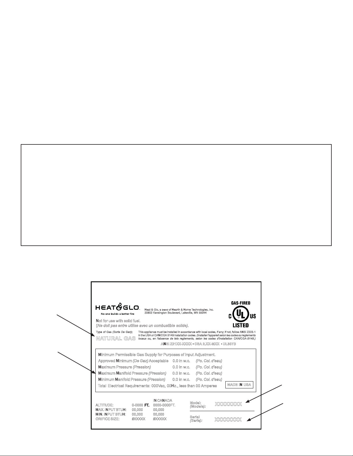
Listing Label Information/Location
This product may be coveredby one or more ofthe following patents: (Nos produitssont couverts par un ouplusieurs des brevets suivants): (United States)
4593510,4686807, 4766876, 4793322, 4811534, 5000162, 5016609, 5076254, 5113843, 5191877, 5218953, 5263471, 5328356,5341794, 5347983, 5429495,
5452708,5542407, 5601073, 5613487, 5647340, 5688568, 5762062, 5775408, 5890485,5931661, 5941237, 594711 2,5996575, 6006743,6019099, 6048195,
6053165, 6145502, 6170481, 6237588, 6296474, 6374822, 6413079, 6439226, 6484712, 6543698, 6550687, 6601579, 6672860, 6688302B2, 6715724B2,
6729551, 6736133, 6748940, 6748942, D320652,D445174, D462436; (Canada)1297749, 2195264, 2225408;or other U.S. and foreignpatents pending (ou
autresbrevetsamericainsetetrangersenattente).
Type of Gas
Not for use with solid fuel .
(Ne doit pas entre utilise avec un combustible solide).
Ty pe of Gas (Sorte De Gaz) :
NATURA L GAS
Gas and Electric
Information
Minimum Permissible Gas Supply for Purpos es of Input Adjustment .
Approved Minimum (De Gaz) Acceptabl e 0. 0 in w. c. (Po. Col. d’eau)
Maximum Pressure (Pression) 0. 0 in w. c. (Po. Col. d’eau)
Maximum Manifold Pressure (Pression) 0. 0 in w. c. (Po. Col. d’eau)
Minimum Manifold Pressure (Pression) 0. 0 in w. c. (Po. Col. d’eau)
T o tal Electrical Requirements: 000V ac, 00Hz., less than 00 Ampere s
AL TI TUDE : 0-0000 FT . 0000-0000FT .
MAX. INPU T BTUH: 00,000 00,000
MIN. INPU T BTUH: 00,000 00,000
ORIFICE SIZE: #XXXXX #XXXXX
The model information regarding your specifi c appliance can be found on
the rating plate usually located in the control area of the appliance.
He at & Gl o, a of Hearth & Ho me T e chnologies, Inc.
20802 Kensington Boulevard, Lakeville, MN 5504 4
This appliance must be installed in accordance with local codes, if any; if not, follow ANSI Z223.1
in the USA or CAN/CG A B149 installation codes. (Installer l’ appa re il selon les codes ou regl emen ts
lo caux ou , en l’absence de tels reglements, selon les codes d’in stallation CAN/CGA-B149.)
bran d
ANSI Z21X X-XXXX · CS A 2.XX-MXX · UL307B
IN CANADA
Mode l:
(Modele):
Serial
(Serie):
XXXXXXXX
XXXXXXXX
MADE IN US A
Model Number
Serial Number
Heat & Glo • Escape-36DV • 2012-900 • Rev. AB • 10/082
Page 3

Table of Contents
1 Listing and Code Approvals
A. Appliance Certifi cation . . . . . . . . . . . . . . . . . . . . . . . . . . . . 4
B. BTU Specifi cations . . . . . . . . . . . . . . . . . . . . . . . . . . . . . . . 4
C. High Altitude Installations . . . . . . . . . . . . . . . . . . . . . . . . . . 4
D. Non-Combustible Materials Specifi cation. . . . . . . . . . . . . . 4
E. Combustible Materials Specifi cation . . . . . . . . . . . . . . . . . 4
F. Electrical Codes . . . . . . . . . . . . . . . . . . . . . . . . . . . . . . . . . 4
G. Requirements for the Commonwealth of Massachusetts . . 5
2 Getting Started
A. Design and Installation Considerations . . . . . . . . . . . . . . . 6
B. Tools and Supplies Needed . . . . . . . . . . . . . . . . . . . . . . . . 6
C. Inspect Appliance and Components . . . . . . . . . . . . . . . . . . 6
D. Inspect Firebox . . . . . . . . . . . . . . . . . . . . . . . . . . . . . . . . . . 7
3 Framing and Clearances
A. Selecting Appliance Location . . . . . . . . . . . . . . . . . . . . . . . 8
B. Constructing the Appliance Chase . . . . . . . . . . . . . . . . . . . 9
C. Clearances . . . . . . . . . . . . . . . . . . . . . . . . . . . . . . . . . . . . . 9
D. Mantel Projections . . . . . . . . . . . . . . . . . . . . . . . . . . . . . . 10
E. Hearth Extension . . . . . . . . . . . . . . . . . . . . . . . . . . . . . . . 10
4 Termination Locations
A. Vent Termination Minimum Clearances . . . . . . . . . . . . . . .11
5 Vent Information and Diagrams
A. Vent Table Key . . . . . . . . . . . . . . . . . . . . . . . . . . . . . . . . . 13
B. Use of Elbows . . . . . . . . . . . . . . . . . . . . . . . . . . . . . . . . . 13
C. Measuring Standards . . . . . . . . . . . . . . . . . . . . . . . . . . . . 13
D. Vent Diagrams . . . . . . . . . . . . . . . . . . . . . . . . . . . . . . . . . 14
6 Vent Clearances and Framing
A. Pipe Clearances to Combustibles . . . . . . . . . . . . . . . . . . 19
B. Wall Penetration Framing . . . . . . . . . . . . . . . . . . . . . . . . . 19
C. Vertical Penetration Framing . . . . . . . . . . . . . . . . . . . . . . 20
7 Appliance Preparation
A. Removing Non-combustible Facing Material Assembly . . 21
B. Securing and Leveling the Appliance . . . . . . . . . . . . . . . . 21
C. Installing Non-combustible Facing Material . . . . . . . . . . . 22
8 Installing Vent Pipe
A. Assembly of Vent Sections (DVP Pipe) . . . . . . . . . . . . . . 23
B. Disassembly of Vent Sections . . . . . . . . . . . . . . . . . . . . . 25
C. Installing Heat Shield and Horizontal Termination Cap . . 26
D. Installing Roof Flashing and
Vertical Termination Cap . . . . . . . . . . . . . . . . . . . . . . . . . 27
9 Gas Information
A. Fuel Conversions . . . . . . . . . . . . . . . . . . . . . . . . . . . . . . . 29
B. Gas Pressures . . . . . . . . . . . . . . . . . . . . . . . . . . . . . . . . . 29
C. Gas Connection . . . . . . . . . . . . . . . . . . . . . . . . . . . . . . . . 29
10 Electrical Information
A. Recommendation for Wire . . . . . . . . . . . . . . . . . . . . . . . . 31
B. Connecting to the Appliance. . . . . . . . . . . . . . . . . . . . . . . 31
C. Intellifi re Ignition System Wiring . . . . . . . . . . . . . . . . . . . . 31
D. Junction Box Installation. . . . . . . . . . . . . . . . . . . . . . . . . . 33
11 Finishing
A. Mantel Projections . . . . . . . . . . . . . . . . . . . . . . . . . . . . . . 34
B. Facing Material . . . . . . . . . . . . . . . . . . . . . . . . . . . . . . . . . 34
12 Appliance Setup
A. Remove Shipping Materials . . . . . . . . . . . . . . . . . . . . . . . 36
B. Clean the Appliance . . . . . . . . . . . . . . . . . . . . . . . . . . . . . 36
C. Accessories . . . . . . . . . . . . . . . . . . . . . . . . . . . . . . . . . . . 36
D. Installing the Optional Heat-Zone-Gas Kit . . . . . . . . . . . . 36
E. Ember Placement. . . . . . . . . . . . . . . . . . . . . . . . . . . . . . . 36
F. Positioning the Logs . . . . . . . . . . . . . . . . . . . . . . . . . . . . . 37
G. Glass Assembly . . . . . . . . . . . . . . . . . . . . . . . . . . . . . . . . 41
H. Grilles and Trim . . . . . . . . . . . . . . . . . . . . . . . . . . . . . . . . 41
I. Air Shutter Setting . . . . . . . . . . . . . . . . . . . . . . . . . . . . . . 41
13 Operating Instructions
A. Before Lighting Appliance. . . . . . . . . . . . . . . . . . . . . . . . . 42
B. Lighting Appliance . . . . . . . . . . . . . . . . . . . . . . . . . . . . . . 43
C. After Appliance is Lit . . . . . . . . . . . . . . . . . . . . . . . . . . . . . 44
D. Frequently Asked Questions . . . . . . . . . . . . . . . . . . . . . . 44
14 Troubleshooting
A. Intellifi re Ignition System . . . . . . . . . . . . . . . . . . . . . . . . . 45
15 Maintaining and Servicing Appliance
A. Maintenance Tasks . . . . . . . . . . . . . . . . . . . . . . . . . . . . . . 47
B. Replacing Light Bulb . . . . . . . . . . . . . . . . . . . . . . . . . . . . 48
16 Reference Materials
A. Appliance Dimension Diagram . . . . . . . . . . . . . . . . . . . . . 50
B. Vent Components Diagrams . . . . . . . . . . . . . . . . . . . . . . 51
C. Service Parts List . . . . . . . . . . . . . . . . . . . . . . . . . . . . . . 56
D. Limited Lifetime Warranty . . . . . . . . . . . . . . . . . . . . . . . . . 58
E. Contact Information . . . . . . . . . . . . . . . . . . . . . . . . . . . . . 60
= Contains updated information.
Heat & Glo • Escape-36DV • 2012-900 • Rev. AB • 10/08 3
Page 4
1
1
Listing and Code Approvals
A. Appliance Certifi cation
MODELS: Escape-36DV, Escape-36DVLP
LABORATORY: Underwriters Laboratories, Inc. (UL)
TYPE: Direct Vent Gas Appliance Heater
STANDARD: ANSI Z21.88-2000 • CSA2.33-M98 • UL307B
This product is listed to ANSI standards for “Vented Gas
Appliance Heaters” and applicable sections of “Gas Burning Heating Appliances for Manufactured Homes and
Recreational Vehicles”, and “Gas Fired Appliances for
Use at High Altitudes”.
NOT INTENDED FOR USE AS A PRIMAR Y HEAT SOURCE.
This appliance is tested and approved as either supplemental room heat or as a decorative appliance. It should not be
factored as primary heat in residential heating calculations.
B. BTU Specifi cations
Models
(U.S. or Canada)
US
Escape-36DV
Escape-36DVLP
Note: This installation must conform with local codes. In the
absence of local c odes you must comply w ith the National
Fuel Gas Code, ANSI Z223.1 -latest edition in the U.S.A. and
the CAN/CGA B149 Installation Codes in Canada.
(0-2000 FT)
CANADA
(2000-4500 FT)
US
(0-2000 FT)
CANADA
(2000-4500 FT)
Maximum
Input
BTU/h
41,000 27,000 30
36,900 24,300 31
40,000 31,000 49
36,000 27,900 50
Minimum
Input
BTU/h
Orifi ce
Size
(DMS)
C. High Altitude Installations
U.L. Listed gas appliances are tested and approved without requiring changes for elevations from 0 to 2000 feet in
the U.S.A. and Canada.
When installing this appliance at an elevation above 2000
feet, it may be necessary to decrease the input rating
by changing the existing burner orifi ce to a smaller size.
Input rate should be reduced by 4% for each 1000 feet
above a 2000 foot elevation in the U.S.A., or 10% for elevations between 2000 and 4500 feet in Canada. If the
heating value of the gas has been reduced, these rules
do not apply . To identify the proper orifi ce size, check with
the local gas utility.
If installing this appliance at an elevation above 4500 feet
(in Canada), check with local authorities.
WARNING
Do NOT use this appliance if any part has been under water.
Immediately call a qualifi ed service technician to inspect the
appliance and to replace any part of the control system and
any gas control which has been under water.
D. Non-Combustible Materials Specifi cation
Material which will not ignite and burn. Such materials are
those consisting entirely of steel, iron, brick, tile, concrete,
slate, glass or plasters, or any combination thereof.
Materials that are reported as passing ASTM E 136,
Standard Test Method for Behavior of Materials in a
Vertical Tube Furnace at 750ºC, shall be considered
non-combustible materials.
E. Combustible Materials Specifi cation
Materials made of or surfaced with wood, compressed
paper, plant fi bers, plastics, or other material that can ig-
nite and burn, whether fl ame proofed or not, or whether
plastered or unplastered shall be considered combustible
materials.
F. Electrical Codes
NOTICE: This appliance must be electrically wired and
grounded in accordance with local codes or, in the absence
of local codes, with National Electric Code ANSI/NFPA
70-latest edition or the Canadian Electric Code CSA
C22.1.
• A 110-120 VAC circuit for this product must be protected
with ground-fault circuit-interrupter protection, in compliance
with the applicable electrical codes, when it is installed in
locations such as in bathrooms or near sinks.
Heat & Glo • Escape-36DV • 2012-900 • Rev. AB • 10/084
Page 5

Note: The following requirements reference various
Massachuset ts and national codes not contained in this
document.
G. Requirements for the Commonwealth of
Massachusetts
For all side wall horizontally vented gas fueled equipment
installed in every dwelling, building or structure used in
whole or in part for residential purposes, including those
owned or operated by the Commonwealth and where the
side wall exhaust vent termination is less than seven (7)
feet above fi nished grade in the area of the venting, in-
cluding but not limited to decks and porches, the following
requirements shall be satisfi ed:
Installation of Carbon Monoxide Detectors
At the time of installation of the side wall horizontal vented
gas fueled equipment, the installing plumber or gas fi tter
shall observe that a hard wired carbon monoxide detector
with an alarm and battery back-up is installed on the fl oor
level where the gas equipment is to be installed. In addition, the installing plumber or gas fi tter shall observe that
a battery operated or hard wired carbon monoxide detector with an alarm is installed on each additional level of
the dwelling, building or structure served by the side wall
horizontal vented gas fueled equipment. It shall be the
responsibility of the property owner to secure the services
of qualifi ed licensed professionals for the installation of
hard wired carbon monoxide detectors.
In the event that the side wall horizontally vented gas fueled equipment is installed in a crawl space or an attic,
the hard wired carbon monoxide detector with alarm and
battery back-up may be installed on the next adjacent
fl oor level.
In the event that the requirements of this subdivision can
not be met at the time of completion of installation, the
owner shall have a period of thirty (30) days to comply
with the above requirements; provided, however, that during said thirty (30) day period, a battery operated carbon
monoxide detector with an alarm shall be installed.
Inspection
The state or local gas inspector of the side wall horizontally vented gas fueled equipment shall not approve the
installation unless, upon inspection, the inspector observes carbon monoxide detectors and signage installed
in accordance with the provisions of 248 CMR 5.08(2)(a)1
through 4.
Exemptions
The following equipment is exempt from 248 CMR
5.08(2)(a)1 through 4:
• The equipment listed in Chapter 10 entitled “Equip-
ment Not Required To Be Vented” in the most current
edition of NFPA 54 as adopted by the Board; and
• Product Approved side wall horizontally vented gas fu-
eled equipment installed in a room or structure separate from the dwelling, building or structure used in
whole or in part for residential purposes.
MANUFACTURER REQUIREMENTS
Gas Equipment Venting System Provided
When the manufacturer of Product Approved side wall
horizontally vented gas equipment provides a venting
system design or venting system components with the
equipment, the instructions provided by the manufacturer
for installation of the equipment and the venting system
shall include:
• Detailed instructions for the installation of the venting
system design or the venting system components; and
• A complete parts list for the venting system design or
venting system.
Gas Equipment Venting System NOT Provided
When the manufacturer of a Product Approved side wall
horizontally vented gas fueled equipment does not provide the parts for venting the fl ue gases, but identifi es
“special venting systems”, the following requirements
shall be satisfi ed by the manufacturer:
Approved Carbon Monoxide Detectors
Each carbon monoxide detector as required in accordance with the above provisions shall comply with NFPA
720 and be ANSI/UL 2034 listed and IAS certifi ed.
Signage
A metal or plastic identifi cation plate shall be permanent-
ly mounted to the exterior of the building at a minimum
height of eight (8) feet above grade directly in line with the
exhaust vent terminal for the horizontally vented gas fueled heating appliance or equipment. The sign shall read,
in print size no less than one-half (1/2) inch in size, “GAS
VENT DIRECTLY BELOW. KEEP CLEAR OF ALL OBSTRUCTIONS”.
Heat & Glo • Escape-36DV • 2012-900 • Rev. AB • 10/08 5
• The referenced “special venting system” instructions
shall be included with the appliance or equipment installation instructions; and
• The “special venting systems” shall be Product Ap-
proved by the Board, and the instructions for that system shall include a parts list and detailed installation
instructions.
A copy of all installation instructions for all Product Approved side wall horizontally vented gas fueled equipment, all venting instructions, all parts lists for venting
instructions, and/or all venting design instructions shall
remain with the appliance or equipment at the completion
of the installation.
See Gas Connection section for additional Commonwealth of Massachusetts requirements.
Page 6
2
2
Getting Started
A. Design and Installation Considerations
Heat & Glo direct vent gas appliances are designed to
operate with all combustion air siphoned from outside of
the building and all exhaust gases expelled to the outside. No additional outside air source is required.
CAUTION
Check building codes prior to installation.
• Installation MUST comply with local, regional, state and
national codes and regulations.
• Consult local building, fi re offi cials or authorities having jurisdic-
tion about restrictions, installation inspection, and permits.
When planning an appliance installation, it’s necessary to
determine the following information before installing:
• Where the appliance is to be installed.
• The vent system confi guration to be used.
• Gas supply piping.
• Electrical wiring.
• Framing and fi nishing details.
• Whether optional accessories—devices such as a fan,
wall switch, or remote control—are desired.
C. Inspect Appliance and Components
WARNING
Inspect appliance and components for damage.
Damaged parts may impair safe operation.
• Do NOT install damaged components.
• Do NOT install incomplete components.
• Do NOT install substitute components.
Report damaged parts to dealer.
• Carefully remove the appliance and components from
the packaging.
• The vent system components and trim doors are shipped
in separate packages.
• The gas logs may be packaged separately and must be
fi eld installed.
• Report to your dealer any parts damaged in shipment,
particularly the condition of the glass.
• Read all of the instructions before starting the installation. Follow these instructions carefully during the
installation to ensure maximum safety and benefi t.
WARNING
WARNING
Keep appliance dry.
• Mold or rust may cause odors.
• Water may damage controls.
B. Tools and Supplies Needed
Before beginning the installation be sure that the following
tools and building supplies are available.
Reciprocating saw Framing material
Pliers Hi temp caulking material
Hammer Gloves
Phillips screwdriver Framing square
Flat blade screwdriver Electric drill and bits (1/4 in.)
Plumb line Safety glasses
Level 1/2 - 3/4 inch length, #6 or #8 Self-drilling screws
Manometer Voltmeter
Tape measure Noncorrosive leak check solution
One 1/4 inch female connection (for optional fan).
• Installation and use of any damaged appliance or vent
system component.
• Modifi cation of the appliance or vent system.
• Installation other than as instructed by Hearth & Home
Technologies.
• Improper positioning of the gas logs or the glass door.
• Installation and/or use of any component part not approved
by Hearth & Home Technologies.
Any such action may cause a fi re hazard.
Hearth & Home Technologies disclaims any
responsibility for, and the warranty will be voided
by, the following actions:
Heat & Glo • Escape-36DV • 2012-900 • Rev. AB • 10/086
Page 7

D. Inspect Firebox
Surface cracking or crazing of fi rebrick material is normal
and expected. The following types of cracks are acceptable
and do not require replacement of the unit or the fi rebox:
• Cracks that do not propagate entirely thru the material.
• Light fracture lines or “spider-webbing” on the surface of
the material.
• Cracks that are less than 1/32 in. wide and less than 3
in. long.
• If cosmetically unacceptable, such cracks may be
repaired with the SRV-PACK service kit. See Service
Parts List.
Cracks that are unacceptable:
• Cracks greater than 1/32 in. wide and 3 in. long are at
risk of growing.
• Cracks that penetrate entirely through the firebrick
material.
Inspection for cracking should be run when the appliance
is cool. Cracks tend to close as the appliance heats up.
Heat & Glo • Escape-36DV • 2012-900 • Rev. AB • 10/08 7
Page 8
3
3
Framing and Clearances
Note:
• Illustrations reflect typical installations and are FOR
DESIGN PURPOSES ONLY.
• Illustrations/diagrams are not drawn to scale.
• Actual installation may vary due to individual design
preference.
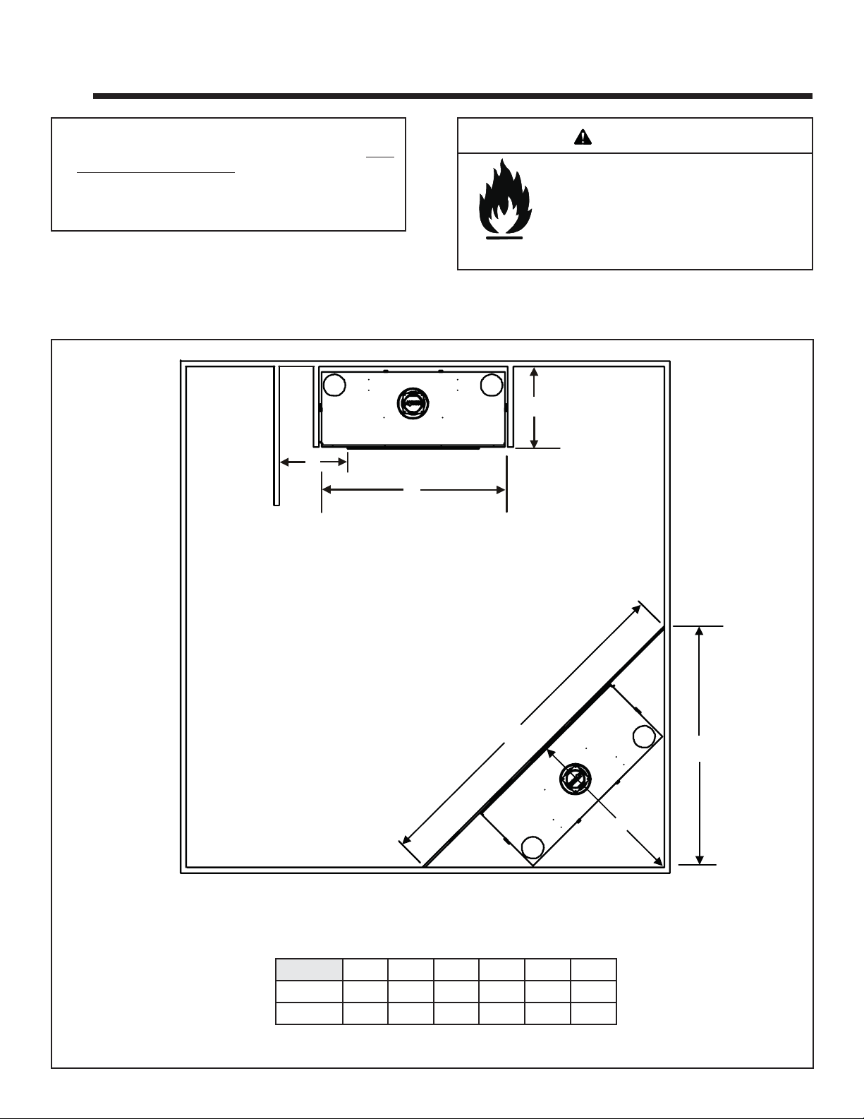
A. Selecting Appliance Location
When selecting a location for your appliance it is important to
consider the required clearances to walls (see fi gure 3.1).
F
WARNING
Fire Risk
Provide adequate clearance:
• Around air openings
• To combustibles
• For service access
Locate appliance away from traffi c areas.
Note: For actual appliance dimensions refer to Section 16.
B
A
Figure 3.1 Appliance Locations
E
D
C
In addition to these framing dimensions, also reference the following sections:
• Clearances and Mantel Projections (Sections 3.C and 3.D)
• Vent Clearances and Framing (Section 6).
ABCDEF
Inches 51-1/2 22 46-3/4 66 93-3/8 7-1/2
Millimeters 1308 559 1187 1676 2372 190
Heat & Glo • Escape-36DV • 2012-900 • Rev. AB • 10/088
Page 9
B. Constructing the Appliance Chase
A chase is a vertical boxlike structure built to enclose the
gas appliance and/or its vent system. Vertical vents that
run on the outside of a building may be, but are not required to be, installed inside a chase.
Construction of the chase may vary with the type of building. These instructions are not substitutes for the requirements of local building codes. Local building codes MUST
be checked.
Chases should be constructed in the manner of all outside walls of the home to prevent cold air drafting problems. The chase should not break the outside building
envelope in any manner.
Walls, ceiling, base plate and cantilever fl oor of the chase
should be insulated. Vapor and air infi ltration barriers
should be installed in the chase as per regional codes for
the rest of the home. Additionally, in regions where cold
air infi ltration may be an issue, the inside surfaces may be
sheetrocked and taped for maximum air tightness.
To further prevent drafts, the wall shield and ceiling
fi restops should be caulked with high temperature caulk
to seal gaps. Gas line holes and other openings should
be caulked with high temp caulk or stuffed with unfaced
insulation. If the appliance is being installed on a cement
slab, a layer of plywood may be placed underneath to prevent conducting cold up into the room.
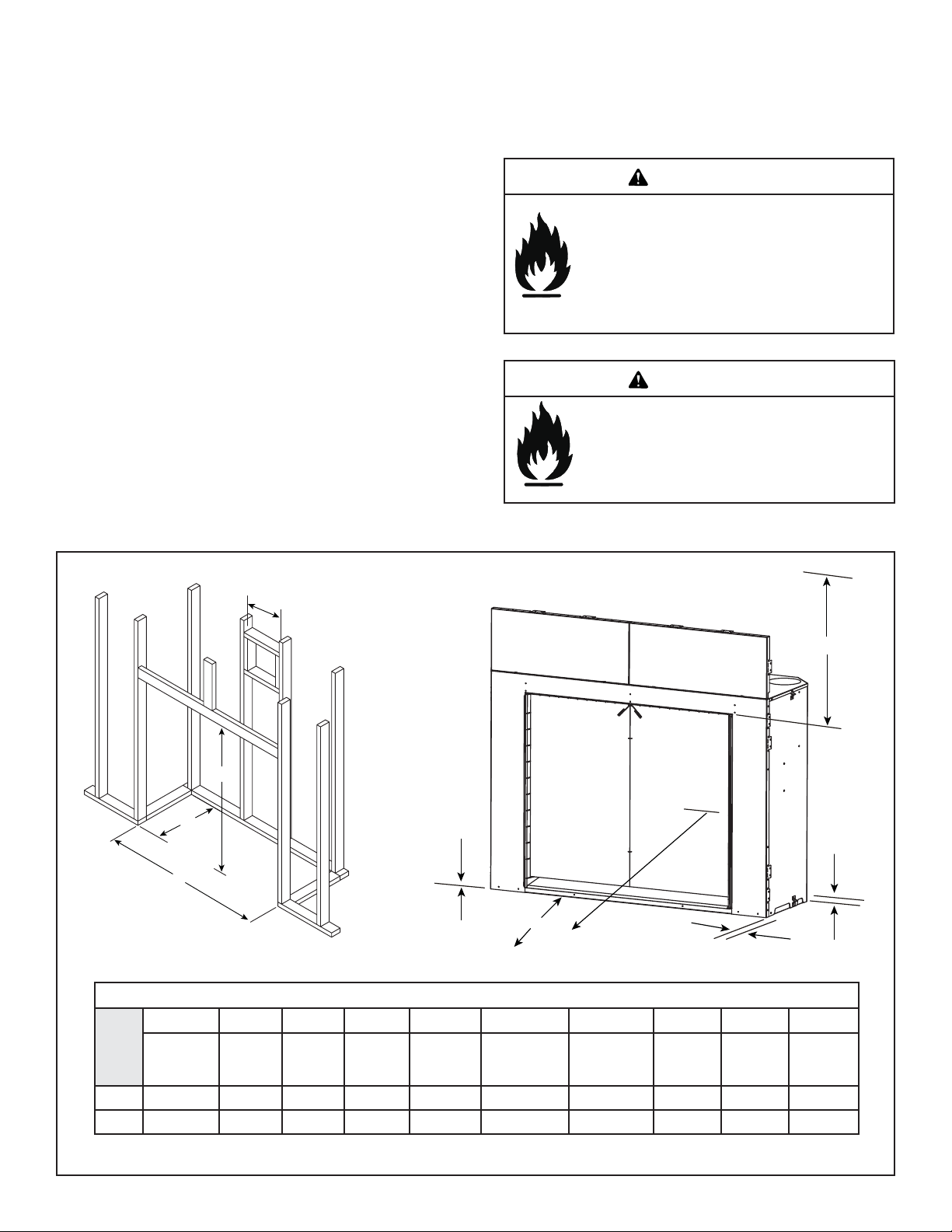
C. Clearances
WARNING
Fire Risk.
Odor Risk.
• Install appliance on hard metal or wood surfaces
extending full width and depth of appliance.
• Do NOT install appliance directly on carpeting,
vinyl, tile or any combustible material other than
wood.
WARNING
Fire Risk.
• Construct chase to all clearance specifi cations
in manual.
• Locate and install appliance to all clearance
specifi cations in manual.
Inches
mm
A
B
C
D
F
G
FROM APPLIANCE
OPENING TO CEILING
J
I
CLEARANCES TO COMBUSTIBLES
ABCDE F G HI J
Rough
Opening
(Vent Pipe)
10 46 22 51-1/2 34-1/2 0 12 1/2 1/2 36
254 1168 559 1308 876 0 305 13 13 914
Rough
Opening
(Height)
Rough
Opening
(Depth)
Rough
Opening
(Width)
Clearance
to Ceiling
Combustible
Floor
Combustible
Flooring
Behind
Appliance
Sides of
Appliance
Front of
Appliance
E
H
Figure 3.2 Clearances to Combustibles
Heat & Glo • Escape-36DV • 2012-900 • Rev. AB • 10/08 9
Page 10
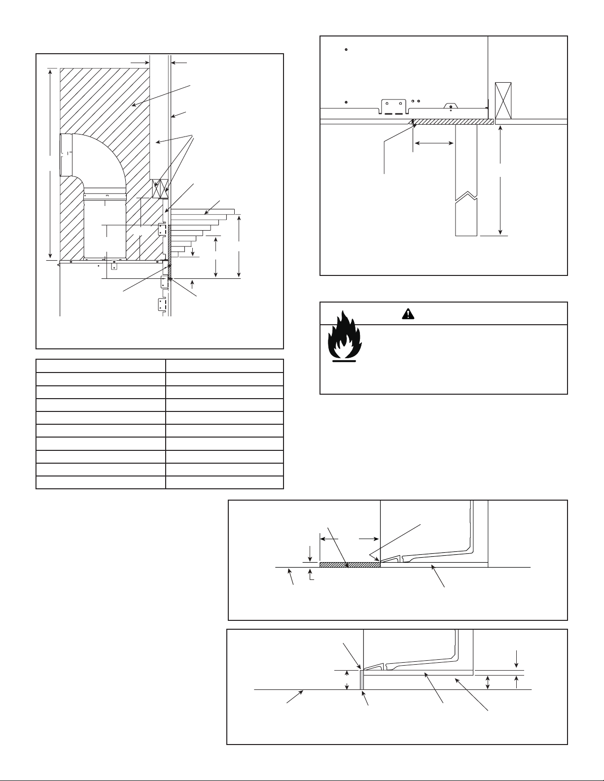
D. Mantel Projections
36 IN.
11-1/2 IN.
10 IN.
MINIMUM
3-1/2 IN.
NO COMBUSTIBLES
IN THIS AREA
FINISH WALL
COMBUSTIBLE
COMBUSTIBLE
FRAMING
METALPANELS
(PROVIDED)
COMBUSTIBLE
PROJECTIONS
10-1/2
9
7-1/2
6
4-3/4
3-1/2
2-1/4
1
MINIMUM
8 IN.
4 IN.
12
12 IN.
7-1/2 IN.
MINIMUM
UNLIMITED
NON-COMBUSTIBLE
MATERIAL
Figure 3.4 Clearances to Mantel Legs or Wall Projections
(Acceptable on both sides of opening.)
NON-COMBUSTIBLE
MINIMUM NCH THICKNESS
1/2 I
FACING
TOP OF
FIREPLACE
OPENING
Figure 3.3 Clearances to mantels or other combustibles
above appliance
Height Above Opening Horizontal Mantel Distance
4 in. 1 in.
5 in. 2-1/4 in.
6 in. 3-1/2 in.
7 in. 4-3/4 in.
8 in. 6 in.
9 in. 7-1/2 in.
10 in. 9 in.
11 in. 10-1/2 in.
12 in. 12 in.
E. Hearth Extension
The base of the fi replace may sit on a
combustible surface. The area in front of
the fi replace must be protected by a non-
combustible hearth extension, unless the
fi replace is raised a minimum of 3 inches
above the combustible fl oor or hearth.
See fi gures 3.5 and 3.6.
Figure 3.5 Fireplace sitting on combustible surface.
• An 12 inch minimum hearth extension must be constructed
of non-combustible material.
MARBLE, GRANITE, TILE OR
OTHER NON-COMBUSTIBLE
HEARTH EXTENSION
12 in.
WOOD OR OTHER COMBUSTIBLE
1 in. Max.
FLOOR OR PLATFORM
WARNING
Fire Risk.
Hearth extension required to protect
combustible fl oors in front of appliance.
FRONT EDGE
OF ASH LIP
BOTTOM OF FIREPLACE
FRONT EDGE
OF ASH LIP
WOOD OR OTHER
COMBUSTIBLE
FLOOR OR PLATFORM
4 INCH
COMBUSTIBLES UP TO
1 INCH THICK ALLOWED
UNDER THE OPENING
BOTTOM
OF FIREPLACE
1 INCH
(BUILT INTO UNIT)
3 INCH MIN.
MAY BE
COMBUSTIBLE
MATERIAL
Figure 3.6 Fireplace raised a minimum of 3 inches away from combustible surface.
Heat & Glo • Escape-36DV • 2012-900 • Rev. AB • 10/0810
Page 11
4
4
Termination Locations
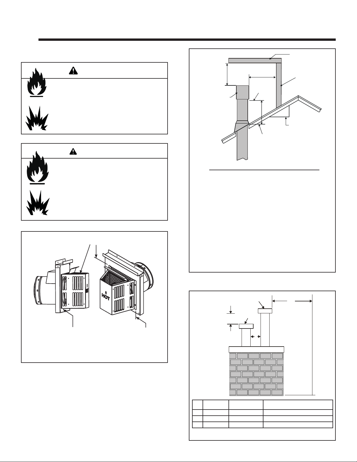
A. Vent Termination Minimum Clearances
WARNING
Fire Risk.
Explosion Risk.
Inspect external vent cap regularly.
• Ensure no debris blocks cap.
• Combustible materials blocking cap may
ignite.
• Restricted air fl ow affects burner operation.
WARNING
Fire Risk.
Explosion Risk.
Maintain vent clearance to combustibles as
specifi ed.
• Do not pack air space with insulation or other
materials.
Failure to keep insulation or other materials
away from vent pipe may cause fi re.
Measure vertical clearances from this surface.
HORIZONTAL
OVERHANG
2 FT.
MIN.
GAS DIRECT VENT
TERMINATION CAP
Roof Pitch H (Min.) Ft.
Flat to 6/12...........................................................1.0*
Over 6/12 to 7/12 .................................................1.25*
Over 7/12 to 8/12 .................................................1.5*
Over 8/12 to 9/12 .................................................2.0*
Over 9/12 to 10/12 ...............................................2.5
Over 10/12 to 11/12 .............................................3.25
Over 11/12 to 12/12 .............................................4.0
Over 12/12 to 14/12 .............................................5.0
Over 14/12 to 16/12 .............................................6.0
Over 16/12 to 18/12 .............................................7.0
Over 18/12 to 20/12 .............................................7.5
Over 20/12 to 21/12 .............................................8.0
20 INCHES MIN.
LOWEST
DISCHARGE
OPENING
H (MIN.) - MINIMUM HEIGHT FROM ROOF
TO LOWEST DISCHARGE OPENING
X
12
ROOF PITCH
VERTICAL
WALL
IS X/ 12
* 3 foot minimum in snow regions
Figure 4.2 Minimum height from roof to lowest discharge
opening
Measure horizontal clearances from this surface.
(See Figure 4.4 for specifi c clearances)
Figure 4.1
Figure 4.2 specifi es minimum vent heights for various
pitched roofs.
GAS, WOOD OR FUEL
OIL TERMINATION
GAS
TERMINATION
C
A
Gas
Termination
A 6 in. 20 in. min. Horizontal distance between terminations
B 20 in. 24 in. min. Distance to perpendicular wall
C 18 in. 18 in. Vertical distance between terminations
Figure 4.3 Multiple Vertical Termination
Wood & Fuel Oil
Termination
B
Comments
Heat & Glo • Escape-36DV • 2012-900 • Rev. AB • 10/08 11
Page 12
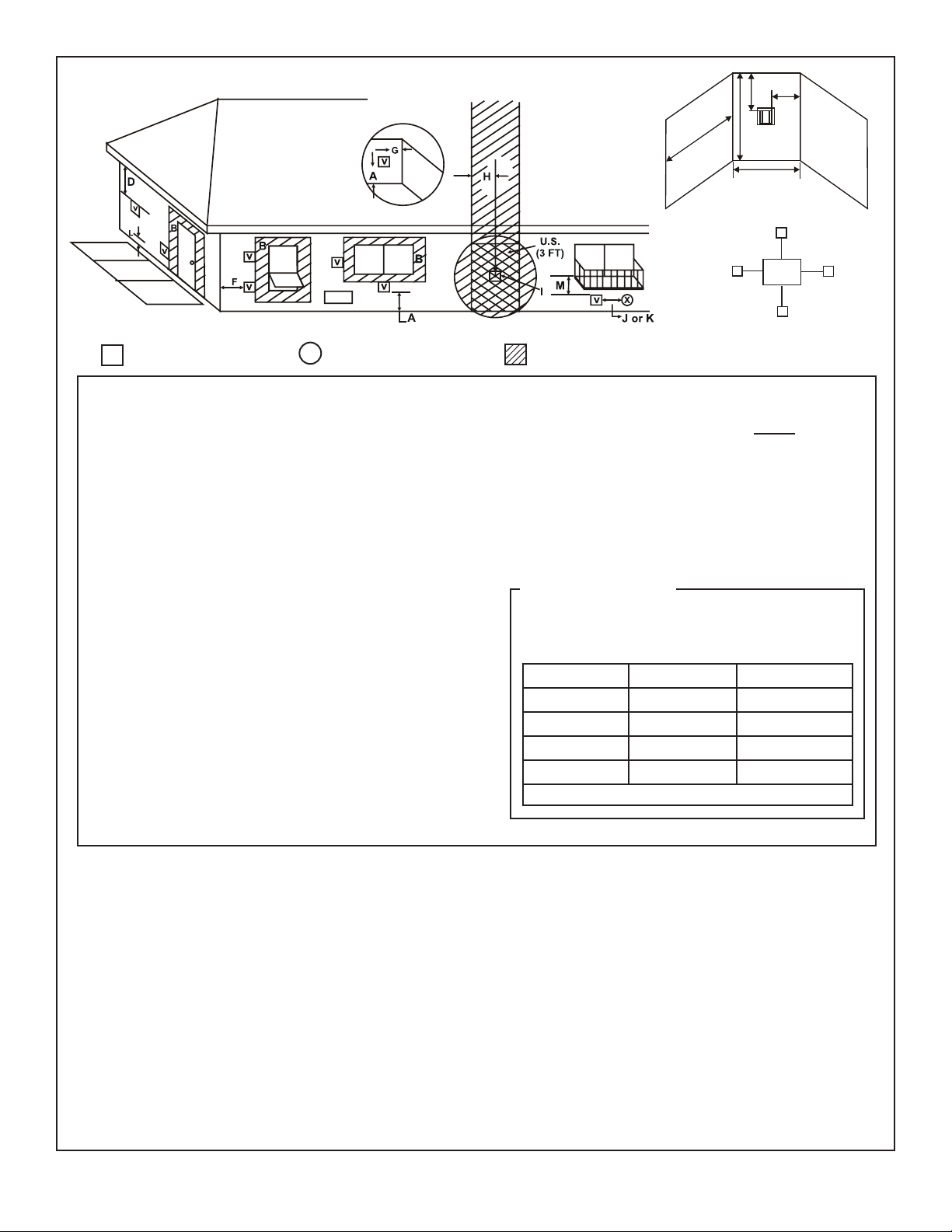
V
R
M
N
P
Q
(See Note 2)
T
S
Electrical
V
Service
V
S
V
D*
= VENT TERMINAL
V
A = 12 inches.................clearances above grade, veranda,
(See Note 1)
X
= AIR SUPPLY INLET
porch, deck or balcony
B = 12 inches.................clearances to window or door
that may be opened, or to permanently closed window. (Glass)
D* = 22 inches.................vertical clearance to unventilated
soffi t or to ventilated soffi t located
above the terminal
*42 inches ................for vinyl clad soffi ts and below
electrical service
F = 9 inches..................clearance to outside corner
G = 6 inches...................clearance to inside corner
H = 3 ft. (Canada) ..........not to be installed above a gas
meter/regulator assembly within 3
feet (90 cm) horizontally from the
center-line of the regulator
I = 3 ft ...........................clearance to gas service regulator
vent outlet
J = 9 inches (U.S.A.)
12 inches (Canada) clearance to non-mechanical
air supply inlet to building or the
combustion air inlet to any other
appliance
K = 3 ft. (U.S.A.)
6 ft. (Canada) ...........clearance to a mechanical (pow-
ered) air supply inlet
= AREA WHERE TERMINAL IS NOT PERMITTED
L** = 7 ft. ......................... clearance above paved
(See Note 1)
sidewalk or a paved driveway
located on public property
M*** = 18 inches................ cl earance under veranda, porch,
deck, balcony or overhang
42 inches ............... vinyl
S = 6 inches................. clearance from sides of electri-
(See Note 5)
cal service
T = 12 inches................ clearance above electrical
(See Note 5)
service
Alcove Applications
N = 6 inches ..................non-vinyl sidewalls
12 inches ................vinyl sidewalls
P = 8 ft.
Q
MIN
1 cap 3 feet 2 x Q
2 caps 6 feet 1 x Q
3 caps 9 feet 2/3 x Q
4 caps 12 feet 1/2 x Q
Q
= # termination caps x 3 R
MIN
= (2 / # termination caps) x Q
MAX
R
MAX
ACTUAL
ACTUAL
ACTUAL
ACTUAL
ACTUAL
** a vent shall not terminate directly above a sidewalk or paved driveway
which is located between two single family dwellings and serves both
dwellings.
*** only permitted if veranda, porch, deck or balcony is fully open on a
minimum of 2 sides beneath the fl oor, or meets Note 2.
Note 1: On private property where termination is less than 7 feet above a
sidewalk, driveway, deck, porch, veranda or balcony, use of a listed cap
shield is suggested. (See vents components page)
Note 2: Termination in an alcove space (spaces open only on one side
and with an overhang) are permitted with the dimensions specifi ed for
vinyl or non-vinyl siding and soffi ts. 1. There must be 3 feet minimum
between termination caps. 2. All mechanical air intakes within 10 feet
of a termination cap must be a minimum of 3 feet below the termination
cap. 3. All gravity air intakes within 3 feet of a termination cap must be a
minimum of 1 foot below the termination cap.
Note 3: Local codes or regulations may require different
clearances.
Note 4: Termination caps may be hot. Consider their proximity to
doors or other traffi c areas.
Note 5: Location of the vent termination must not interfere with
access to the electrical service.
WARNING: In the U.S: V ent system termination is NOT permitted in
screened porches. Y ou must follow side wall, overhang and ground
clearances as stated in the instructions.
In Canada: Vent system termination is NOT permitted in screened
porches. Vent system termination is permitted in porch areas with
two or more sides open. You must follow all side walls, overhang
and ground clearances as stated in the instructions.
Heat & Glo assumes no responsibility for the improper performance
of the appliance when the venting system does not meet these
Figure 4.4 Minimum Clearances for Termination
requirements.
CAUTION: IF EXTERIOR WALLS ARE FINISHED WITH VINYL SIDING, IT IS SUGGESTED THAT A VINYL PROTECTOR KIT BE INSTALLED.
Heat & Glo • Escape-36DV • 2012-900 • Rev. AB • 10/0812
Page 13
5
5
Vent Information and Diagrams
A. Vent Table Key
The abbreviations listed in this vent table key are used in
the vent diagrams.
Symbol Description
First section (closest to appliance) of vertical length
V
1
Second section of vertical length
V
2
First section (closest to appliance) of horizontal length
H
1
Vertical
12 in.
8-1/2 in.
Second section of horizontal length
H
2
WARNING
Fire Hazard.
Explosion Risk.
Asphyxiation Risk.
Do NOT connect this gas appliance to a chimney
fl ue serving a separate solid-fuel or gas burning
appliance.
• Vent this appliance directly outside.
• Use separate vent system for this appliance.
May impair safe operation of this appliance or
other appliances connected to the fl ue.
B. Use of Elbows
CAUTION
ALL vent confi guration specifi cations MUST be followed.
• This product is tested and listed to these specifi cations.
• Appliance performance will suffer if specifi cations are not
followed.
8-1/2 in.
Horizontal
Figure 5.1
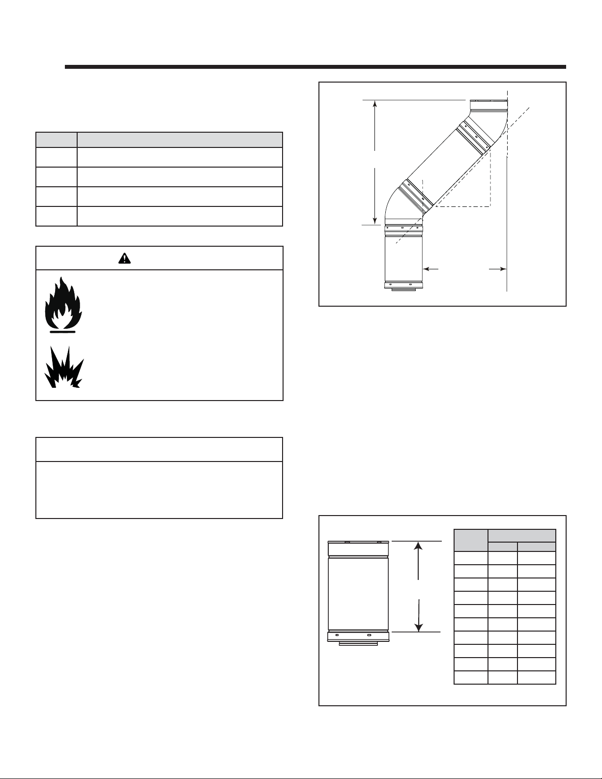
C. Measuring Standards
Vertical and horizontal measurements listed in the vent
diagrams were made using the following standards.
1. Pipe measurements are shown using the effective length
of pipe (see Figure 5.2).
2. Measurements are made from the appliance outer wrap,
not from the standoffs.
3. Horizontal terminations are measured to the outside
mounting surface (fl ange of termination cap) (see
Figure 4.1).
4. V ertical terminations are measured to bottom of termination cap.
5. Horizontal pipe installed level with no rise.
Diagonal runs have both vertical and horizontal vent aspects when calculating the effects. Use the rise for the
vertical aspect and the run for the horizontal aspect (see
Figure 5.1).
Two 45º elbows may be used in place of one 90º elbow . On
45º runs, one foot of diagonal is equal to 8.5 inches horizontal run and 8.5 inches vertical run. A length of straight
pipe is allowed between two 45º elbows (see Figure 5.1).
Heat & Glo • Escape-36DV • 2012-900 • Rev. AB • 10/08 13
Effective
Height/Length
DVP12MI 3 to 12 76 to 305
DVP24MI 3 to 24 76 to 610
Figure 5.2 DVP Pipe Effective Length
Pipe
DVP4 4 102
DVP6 6 152
DVP12 12 305
DVP24 24 610
DVP36 36 914
DVP48 48 1219
DVP6A 3 to 6 76 to 152
DVP12A 3 to 12 76 to 305
Effective Length
Inches Millimeters
Page 14
D. Vent Diagrams
Fire Risk. Explosion Risk.
Do NOT pack insulation or other combustibles between ceiling fi restops.
• ALWAYS maintain specifi ed clearances around venting and fi restop systems.
• Install wall shield and ceiling fi restops as specifi ed.
Failure to keep insulation or other material away from vent pipe may cause fi re.
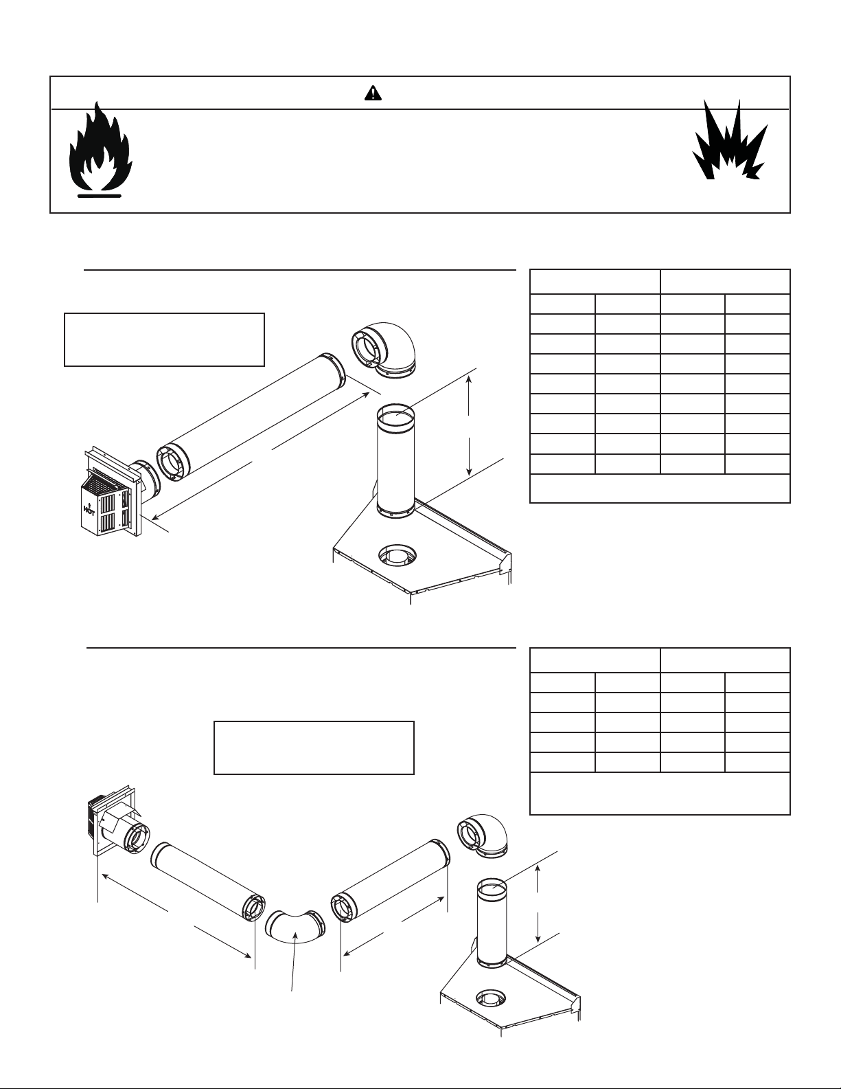
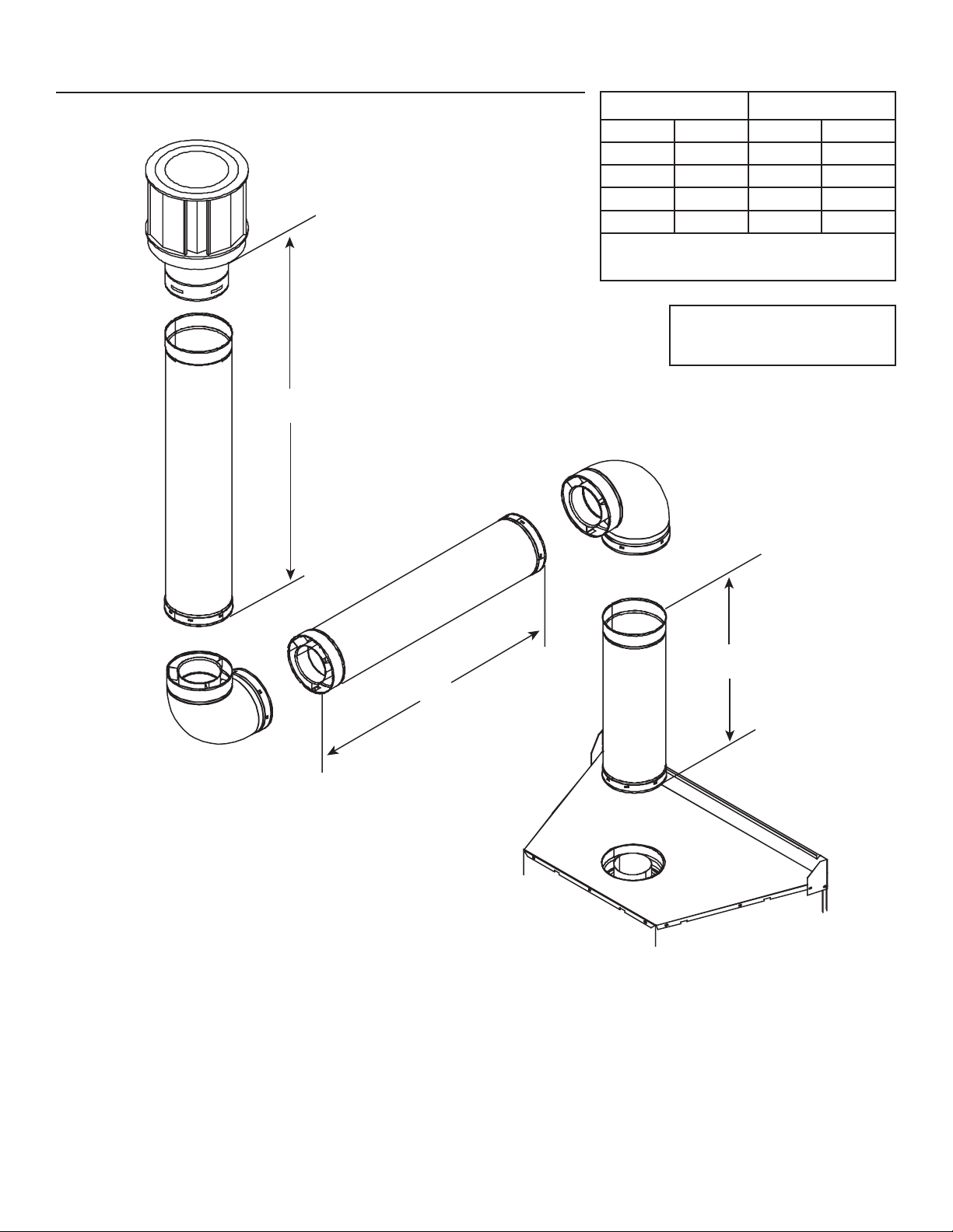
1. Top Vent - Horizontal Termination
WARNING
One Elbow
Note: Must have a 12 inches
minimum vertical vent before
attaching any elbow to the unit.
Figure 5.3
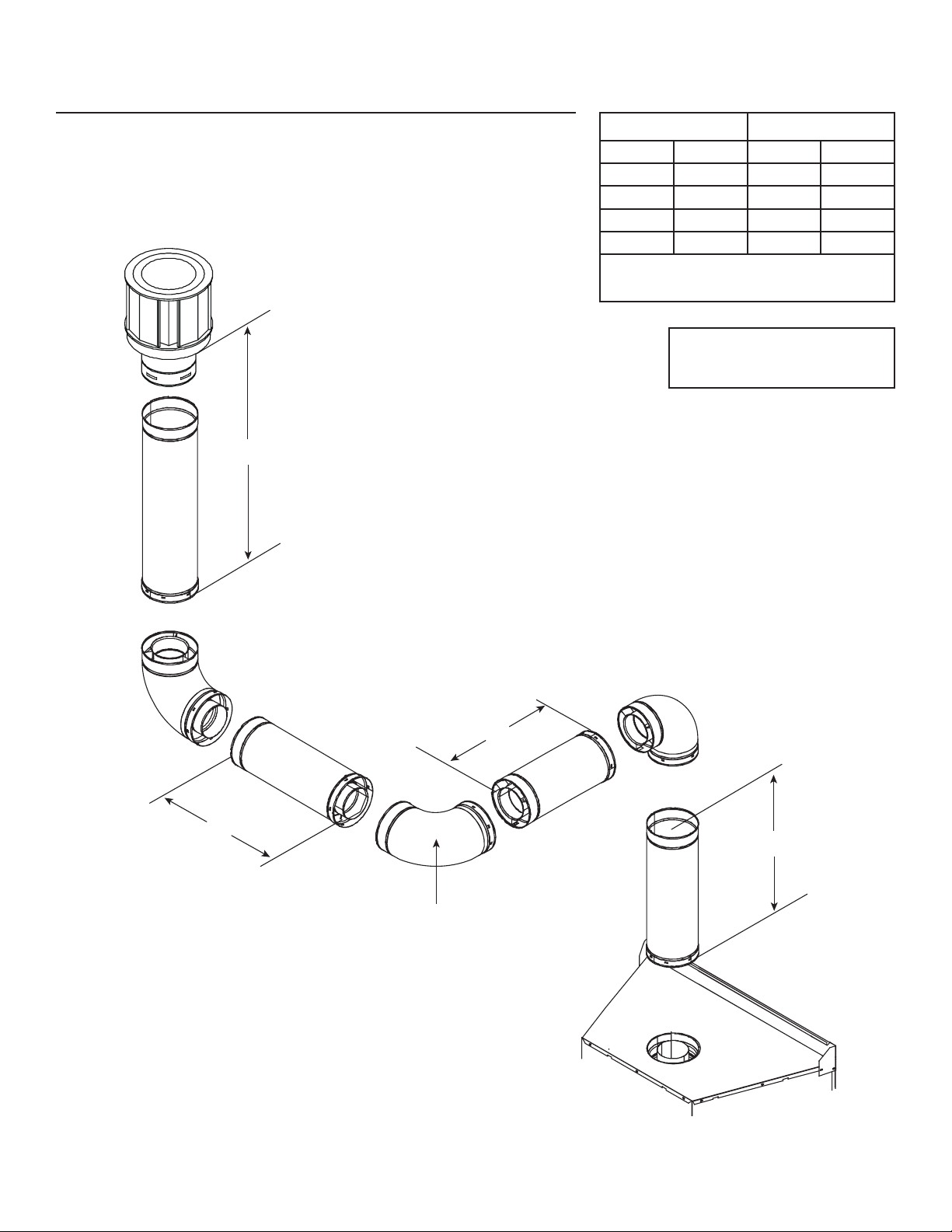
Two Elbows
Note: Must have a 12 inches
minimum vertical vent before
attaching any elbow to the unit.
V1 Minimum H1 Maximum
1 ft. 305 mm 1-1/2 ft. 457 mm
1-1/2 ft. 457 mm 2 ft. 610 mm
2 ft. 610 mm 5 ft. 1524
3 ft. 914 mm 8 ft. 2438
4 ft. 1219 mm 11 ft. 3353
5 ft. 1524 mm 14 ft. 4267
V
1
H
1
6 ft. 1829 mm 17 ft. 5182
7 ft. 2134 mm 20 ft. 6096
8 ft. 2438 mm 23 ft. 7010
+ H1 = 63 ft. (19.2 m) Maximum
V
1
V1 Minimum H1 + H2 Maximum
1 ft. 305 mm 2 ft. 610 mm
1-1/2 ft. 457 mm 2-1/2 ft. 762 mm
2 ft. 610 mm 5-1/2 ft. 1676 mm
3 ft. 914 mm 8-1/2 ft. 2591 mm
4 ft. 1219 mm 11-1/2 ft. 3505 mm
V
+ H1 + H2 = 63 ft. (19.2 m) Maximum
1
H
+ H2 = 23 ft. (7.1 m) Maximum
1
Figure 5.4
V
H
2
INSTALLED
HORIZONTALLY
Heat & Glo • Escape-36DV • 2012-900 • Rev. AB • 10/0814
H
1
1
Page 15
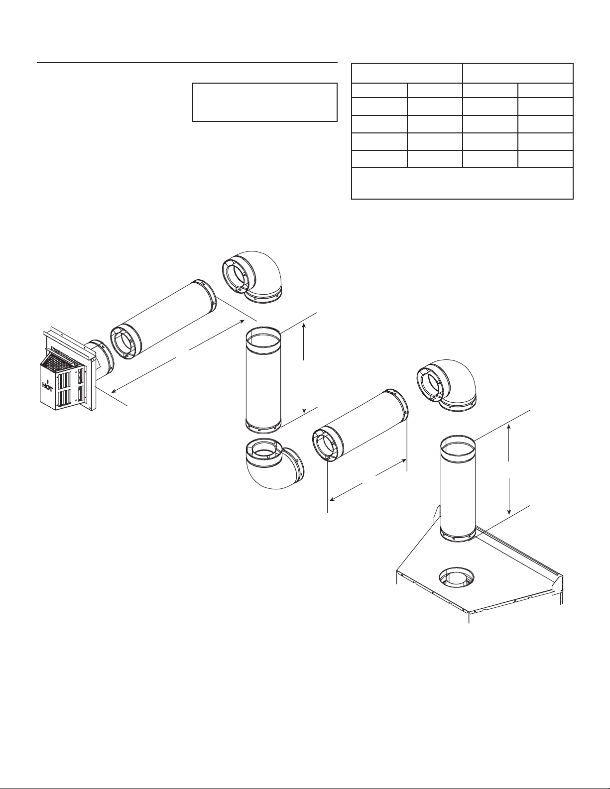
1. Top Vent - Horizontal Termination - (continued)
Three Elbows
Note: Must have a 12 inches
minimum vertical vent before
attaching any elbow to the unit.
H
2
V1 + V2 Minimum H Maximum
1-1/2 ft. 457 mm 1-1/2 ft. 457 mm
2 ft. 610 mm 2 ft. 610 mm
2-1/2 ft. 762 mm 5 ft. 1524
3-1/2 ft. 1067 mm 8 ft. 2438
4-1/2 ft. 1372 mm 11 ft. 3353
+ V2 + H1 + H2 = 63 ft. (19.2 m) Maximum
V
1
H1 + H2 = 23 ft. (7.1 m) Maximum
V
2
Figure 5.5
H
V
1
1
Heat & Glo • Escape-36DV • 2012-900 • Rev. AB • 10/08 15
Page 16
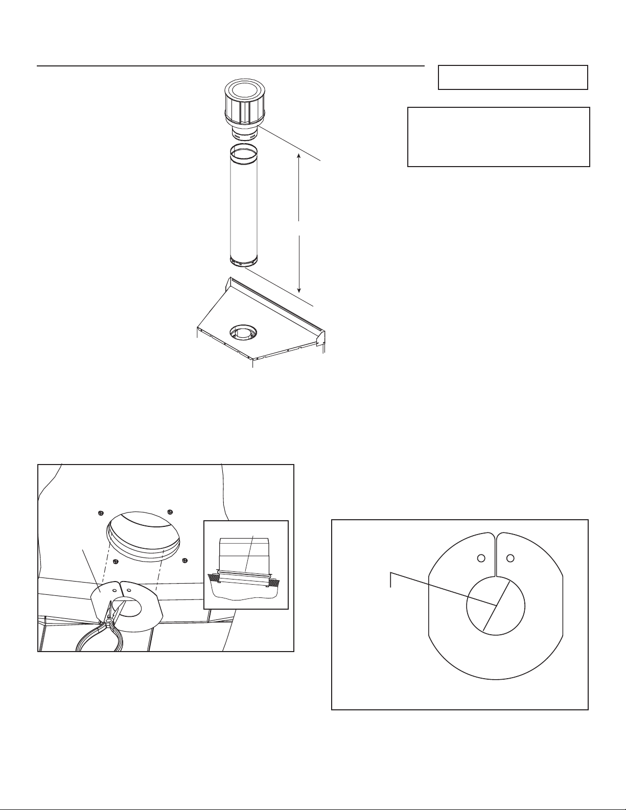
2. Top Vent - Vertical Termination
No Elbow
Figure 5.6
V1 = 40 ft. Max. (12.2 m)
Note: On vertical venting confi gura-
tions install the fl ue restrictor (located
behind the right side panel) per the
following fl ue restrictor instructions.
V
1
Flue Restrictor Instructions
1. The fl ue restrictor (Figure 5.7) is located behind the right
side panel. Use the restrictor if the vertical vent run is
over 20 feet and has NO elbows.
FLUE
RESTRICTOR
Figure 5.7
FLUE RESTRICTOR
2. The restrictor sits inside the 5” diameter collar in the
bead area. Using a needle-nose pliers, insert the tips
of the pliers into the two holes in the restrictor plate.
Squeeze the pliers to fl ex the plate. The edges of the
plate will need to overlap each other. Insert the plate into
the 5” collar from inside the fi rebox. Release the pliers,
the plate will expand into the bead (groove) inside the
collar. Make sure the plate is fully in the groove so the
restrictor cannot fall out (see Figure 5.8).
3”
DIAMETER
Figure 5.8 Flue Restrictor
Heat & Glo • Escape-36DV • 2012-900 • Rev. AB • 10/0816
Page 17
Two Elbows
V
V1 + V2 Minimum H Maximum
1-1/2 ft. 457 mm 2 ft. 610 mm
2 ft. 610 mm 2-1/2 ft. 762 mm
2-1/2 ft. 762 mm 5-1/2 ft. 1676 mm
3-1/2 ft. 1067 mm 8-1/2 ft. 2591 mm
4-1/2 ft. 1372 mm 11-1/2 ft. 3505 mm
+ H1 + V2 = 63 ft. (19.2 m) Maximum
V
1
H1 + H2 = 23 ft. (7.1 m) Maximum
Note: Must have a 12 inches
minimum vertical vent before
attaching any elbow to the unit.
2
Figure 5.9
H
V
1
1
Heat & Glo • Escape-36DV • 2012-900 • Rev. AB • 10/08 17
Page 18
2. Top Vent - Vertical Termination - (continued)
Three Elbows
V1 + V2 Minimum H1 + H2 Maximum
1-1/2 ft. 305 mm 2 ft. 610 mm
2 ft. 457 mm 2-1/2 ft. 762 mm
2-1/2 ft. 610 mm 5-1/2 ft. 1676 mm
3-1/2 ft. 914 mm 8-1/2 ft. 2591 mm
4-1/2 ft. 1219 mm 11-1/2 ft. 3505 mm
+ V2 + H1+ H2= 63 ft. (19.2 m) Maximum
V
1
H1 + H2 = 23 ft. (7.1 m) Maximum
Note: Must have a 12 inches
minimum vertical vent before
attaching any elbow to the unit.
V
2
Figure 5.10
H
1
H
2
INSTALLED
HORIZONTALLY
V
1
Heat & Glo • Escape-36DV • 2012-900 • Rev. AB • 10/0818
Page 19

6
6
Vent Clearances and Framing
A. Pipe Clearances to Combustibles
WARNING
Fire Risk.
Explosion Risk.
Maintain vent clearance to combustibles as
specifi ed.
• Do not pack air space with insulation or
other materials.
Failure to keep insulation or other materials
away from vent pipe may cause fi re.
3 in. TOP
CLEARANCE
1 in. CLEARANCE
AROUND VERTICAL
SECTIONS
1 in. SIDE AND
BOTTOM CLEARANCE
B. Wall Penetration Framing
Combustible Wall Penetration
Frame a hole in a combustible wall for an interior wall
shield fi restop, (Figure 6.3) whenever a wall is penetrated.
Use same size framing materials as those used in the wall
construction. The wall shield fi restop maintains minimum
clearances and prevents cold air infi ltration.
Non-Combustible Wall Penetration
If the hole being penetrated is surrounded by noncombustible materials such as concrete, a hole with diameter one
inch greater than the pipe is acceptable.
Whenever a non-combustible wall is penetrated, the wall
shield fi restop is only required on one side and no heat
shield is necessary.
If your local inspector requires the wall shield fi restop on
both sides, then both wall shield fi restops must have a heat
shield attached to them.
10 in.
Figure 6.1 Pipe Clearances
NOTE: Heat shields MUST overlap by a minimum of 1-1/2 in. (38 mm).
The heat shield is designed to be used on a wall 4 in. to 7-1/4 in.
(102 mm to 184 mm) thick. If wall thickness is less than 4 in. (102
mm) the existing heat shields must be fi eld trimmed. If wall thickness is
greater than 7-1/4 in. (184 mm) a DVP-HSM-B will be required.
HEAT
SHIELD
3 in. TOP
CLEARANCE
HEAT
SHIELD
12 in.
B
A
A* B
55-1/8 in. 54 -1/8 in.
* Shows center of vent framing hole for top venting. The
center of the hole is one (1) inch (25.4 mm) above the
center of the horizontal vent pipe.
Figure 6.3 Exterior Wall Hole
1 in. CLEARANCE
WALL
SHIELD
FIRESTOP
WALL
Figure 6.2 Horizontal Venting Clearances to Combustible
Materials
BOTTOM & SIDES
Heat & Glo • Escape-36DV • 2012-900 • Rev. AB • 10/08 19
Page 20

C. Vertical Penetration Framing
WARNING
Fire Hazard
Keep loose materials or blown
insulation from touching the
vent pipe.
• National building codes recommend
using attic shield to keep loose materials/
blown insulation from contacting vent.
• Hearth & Home Technologies requires
the use of an attic shield.
Installing the Ceiling Firestop
• Frame an opening 10 inches by 10 inches
whenever the vent system penetrates a
ceiling/fl oor (see Figure 6.4).
• Frame the area with the same sized
lumber as used in ceiling/fl oor joist.
• When installing a top vent vertical
termination appliance the hole should be
directly above the appliance, unless the
fl ue is offset.
• Do not pack insulation around the vent.
Insulation must be kept away from the
pipe.
ATTIC ABOVE
10 IN. (254 MM)
10 IN.
(254 MM)
HOLE SHOULD MEASURE
10 IN. X 10 IN.
(254 MM X 254 MM)
INSIDE TO INSIDE
Installing Attic Shield
Note: An additional ceiling fi restop is not
required if attic shield is used.
• Frame opening for attic shield.
• Attic shield may be installed above or
below ceiling (see Figure 6.5).
• Secure with three fasteners on each
side.
• Fold tabs at top of attic shield in toward
vent pipe. Tabs must keep vent pipe
centered within shield.
• Field construct additional shield height if
insulation is deeper than height of attic
shield.
Heat & Glo • Escape-36DV • 2012-900 • Rev. AB • 10/0820
Figure 6.4
BEND TABS IN
AROUND PIPE
3 FASTENERS
ATTIC SHIELD INSTALLED
BELOW CEILING
Figure 6.5 Installing the Attic Shield
PER SIDE
ATTIC SHIELD INSTALLED
ABOVE CEILING
Page 21

7
7
Appliance Preparation
A. Removing Non-combustible Facing Mate-
rial Assembly
The non-combustible assembly is located on the right side
of appliance.
CAUTION
Handle with care.
• Non-combustible material may be damaged if dropped.
• Hold non-combustible pieces in place.
• Remove and save two screws from upper bracket.
• Remove non-combustible pieces.
• Remove and save three screws from lower bracket.
• Discard brackets.
• Replace screws in holes where brackets were attached
to appliance.
B. Securing and Leveling the Appliance
NAILING TABS
(BOTH SIDES)
WARNING
Fire Risk.
• Prevent contact with sagging, loose insulation.
• Do NOT install against combustible materials
such as exposed insulation, plastic and insulation
backer.
CAUTION
Sharp Edges
• Wear protective gloves and safety
glasses during installation.
The diagram shows how to properly position, level, and
secure the appliance (see Figure 7.1). Nailing tabs are provided to secure the appliance to the framing members.
• Place the appliance into position.
• Level the appliance from side to side and front to back.
• Shim the appliance, as necessary. It is acceptable to use
wood shims.
• Use the forward set of nailing tabs. Bend out nailing tabs
on each side.
• Keep nailing tabs fl ush with the framing.
• Secure the appliance to the framing by using nails or
screws through the nailing tabs.
Figure 7.1 Proper positioning, leveling and securing of an
appliance
WARNING
Fire Risk.
• ALWAYS maintain specifi ed
clearances around the appliance.
• Do NOT notch into the framing around the appliance spacers.
Failure to keep insulation, framing or other material away from
the appliance may cause fi re.
Heat & Glo • Escape-36DV • 2012-900 • Rev. AB • 10/08 21
Page 22

NON-COMBUSTIBLE
FACING MATERIAL
(SUPPLIED ATTACHED
TO BACK OF APPLIANCE)
APPLY FASTENERS
FROM FASTENER PACKET
IN THESE AREAS
Figure 7.2 Attaching Non-combustible Facing Material
C. Installing Non-combustible Facing Material
WARNING
Fire Risk.
• Follow these instructions exactly.
• Facing materials must be installed properly to
prevent fi re.
• No materials may be substituted without
authorization by Hearth & Home Technologies.
• Center and attach two top boards to the framing
members. See Figure 7.2.
• Attach left and right side pieces to framing members.
• Use fasteners from fastener packet (in manual bag) in
shaded areas.
• Use regular sheetrock screws in non-shaded areas.
• Use a wet or dry towel or soft brush to remove dust or
dirt from facing material.
• Apply a non-combustible adhesive to attach tile,
stone or other non-combustible fi nishing materials per
manufacturer’s instructions.
NON-COMBUSTIBLE ZONE
41 in.
54 in.
Figure 7.3 Complete Installation of Non-combustible Facing
Material
Heat & Glo • Escape-36DV • 2012-900 • Rev. AB • 10/0822
Page 23

8
8
Installing Vent Pipe
A. Assembly of Vent Sections (DVP Pipe)
WARNING
Do not mix pipe, fi ttings or joining
methods from different manufacturers.
WARNING
Fire Risk
Exhaust Fumes Risk
Impaired Performance of Appliance
• Overlap pipe slip sections at least 1-1/2
inches.
• Use pilot holes for screws.
• Screws must not exceed one inch long.
• Pipe may separate if not properly joined.
Attaching Vent to the Firebox Assembly
T o attach the fi rst pipe section to the collars, slide the male
end of the inner vent of the pipe section over the inner collar
on the fi rebox assembly. At the same time, slide the outer
fl ue over the outer collar on the appliance. Push the pipe
section into the appliance collar until all the lances (see
Figure 8.1) have snapped in place. Tug slightly on the section to confi rm it has completely locked into place.
Assembling Pipe Sections
Insert the inner fl ue of section A into the fl ared inner fl ue of
section B.
Start the outer fl ue of section A over the outer fl ue of section
B (see Figure 8.2). Note: The end of the pipe sections with
the lances/tabs on it will face towards the appliance. Once
both inner and outer fl ues are started, press section A onto
section B fi rmly until all lances have snapped into place.
Check to make sure they have snapped together (see Figure 8.3) and the seams are not aligned (see Figure 8.4).
Tug slightly on section A to confi rm it has completely locked
into place. It is acceptable to use screws no longer than
1 inch to hold outer pipe sections together. If predrilling
holes, do NOT penetrate inner pipe.
For 90° and 45° elbows that are changing the vent direction
from horizontal to vertical, one screw minimum should be
put in the outer fl ue at the horizontal elbow joint to prevent
the elbow from rotating. Use screws no longer than 1 inch.
If predrilling screw holes, do NOT penetrate inner pipe.
High Temperature Silicone Sealant
Commercial, Multi-family (multi-level exceeding two
stories), or High-rise Applications only
Commercial, Multi-family (Multi-level exceeding two
stories), & High-Rise Applications
For Installation into Commercial, multi-family (multi-level exceeding two stories) or high-rise applications: All pipe joints
must be sealed with high temperature silicone, including the
slip section that connects directly to the horizontal termination cap.
• Apply a bead of silicone sealant inside the female outer
pipe joint prior to joining sections. See Figure 8.1
• Only outer pipes are sealed. Do not seal the inner fl ue.
All unit collar, pipe, slip section, elbow and cap outer fl ues
shall be sealed in this manner, unless otherwise stated.
Note: The end of the pipe sections with the lances/tabs on it
will face toward the appliance.
WARNING
Fire Risk
Explosion Risk
If slip section seals are broken during the
removal of the termination cap, gas will leak and
a fi re or explosion may occur.
Do not break silicone seals on slip sections.
Figure 8.1 Lances
A
B
Figure 8.2
Figure 8.3
Heat & Glo • Escape-36DV • 2012-900 • Rev. AB • 10/08 23
Page 24

Note: Make sure that the seams are not aligned to prevent
unintentional disconnection.
CORRECT
Figure 8.4 Seams
INCORRECT
This will secure the slip section to the desired length and
prevent it from separating. The slip section can then be
attached to the next pipe section.
If the slip section is too long, the inner and outer fl ues of
the slip section can be cut to the desired length.
Cut from this end
(outer)
Cut from this end
(inner)
Figure 8.5
Assembling Minimum Installations (MI) Sections
MI sections are non-unitized so that they can be cut to a
certain length. Cut these sections to length from the nonexpanded end (see Figure 8.5).
They can then be attached by fi rst connecting the expanded
end of the MI inner fl ue with the inner pipe from the adjacent
pipe section and securing with three screws. The expanded
portion of the MI inner fl ue must overlap completely with
the unexpanded end of the adjacent pipe section.
The outer fl ue can then be inserted into the adjacent outer
fl ue expanded end and attached to the next pipe section
with three screws. The other end of the MI pipe section can
then be attached by fi tting another pipe section to it and
snapping it together, as normal.
Assembling DVP-12A Slip Sections
The outer fl ue of the slip section should slide over the outer
fl ue of the pipe section and into (inner fl ue) the last pipe
section (see Figure 8.6) .
Pilot hole
Figure 8.6 Slip Section Pilot Holes
Slide together to the desired length, making sure that a
1-1/2 inch outer fl ue overlap is maintained between the
pipe section and slip section.
The pipe and slip section need to be secured by driving
two screws through the overlapping portions of the outer
fl ues using the pilot holes (see Figure 8.7).
Heat & Glo • Escape-36DV • 2012-900 • Rev. AB • 10/0824
Figure 8.7 Screws into Slip Section
Page 25

Securing the Vent Sections
Vertical Sections
Vertical sections of pipe must be supported every 8 feet
after the 25 foot maximum unsupported rise. The vent support or plumber’s strap (spaced 120° apart) may be used
to do this (see Figure 8.8).
Horizontal Sections
Horizontal sections of vent must be supported every 5 feet
with a vent support or plumber’s strap.
Figure 8.8 Securing Vertical Pipe Sections
B. Disassembly of Vent Sections
T o disassemble any two pieces of pipe, rotate either section
(see Figure 8.10), so that the seams on both pipe sections
are aligned (see Figure 8.11). They can then be carefully
pulled apart.
WARNING
Fire Risk.
Explosion Risk.
Combustion Fume Risk.
Use vent run supports per installation
instructions.
Connect vent sections per installation
instructions.
• Maintain all clearances to combustibles.
• Do NOT allow vent to sag below
connection point to appliance.
Improper support may allow vent to sag or separate.
Figure 8.9 Securing Horizontal Pipe Sections
Figure 8.10 Rotate Seams for Disassembly
Figure 8.11 Align and Disassemble Vent Sections
Heat & Glo • Escape-36DV • 2012-900 • Rev. AB • 10/08 25
Page 26

C. Installing Heat Shield and Horizontal Termination Cap
When installing a horizontal termination cap, follow the cap
WARNING
Fire Hazard
Impaired performance of appliance
• Telescoping flue section of termination cap
MUST be used when connecting pipe section
to termination cap.
• Maintain a 1-1/2 inch minimum overlap on
telescoping fl ue section of termination cap.
location guidelines as prescribed by current ANSI Z223.1
and CAN/CGA-B149 installation codes.
WARNING
Burn Risk
• Local codes may require installation of a cap
shield to prevent anything or anyone from
touching the hot cap.
WARNING
Fire Risk
Exhaust Fumes Risk
Impaired Performance of Appliance
• Overlap pipe slip sections at least 1-1/2 inches.
• Use pilot holes for screws.
• Screws must not exceed 1 inch long.
• Pipe may separate if not properly joined.
Heat Shield Requirements for Horizontal Termination
For all horizontally vented appliances, a heat shield MUST
be placed one inch above the top of the vent between the
wall shield fi restop and the base of the termination cap.
There are two sections of the heat shield. One section
is factory-attached to the wall shield fi restop. The other
section is factory-attached to the cap. See Figure 8.12.
If the wall thickness does not allow the required 1-1/2 inch
(38 mm) heat shield overlap when installed, an extended
heat shield (DVP-HSM-B) must be used.
Important Notice: Heat shields may not be fi eld constructed.
Note: Where required, an exterior wall fl ashing is available.
When penetrating a brick wall, a brick extension kit is available
for framing the brick.
NOTE: Heat shields MUST overlap by a minimum of 1-1/2 in. (38 mm).
The heat shield is designed to be used on a wall 4 in. to 7-1/4 in.
(102 mm to 184 mm) thick. If wall thickness is less than 4 in. (102
mm) the existing heat shields must be fi eld trimmed. If wall thickness is
greater than 7-1/4 in. (184 mm) a DVP-HSM-B will be required.
HEAT SHIELD OR
EXTENDED
WALL SHIELD
FIRESTOP
OUTER VENT
INNER VENT
VENT DEPTH FROM BACK OF APPLIANCE TO
OUTSIDE SURFACE OF EXTERIOR WALL
HEAT SHIELD
SLIP SECTION
CAN BE EXTENDED
(SEE CHART BELOW)
INTERIOR
HEAT SHIELD
1-1/2 IN. (38 MM) MIN.
OVERLAP
SHEATHING
EXTERIOR
The extended heat shield (DVP-HSM-B) may need to
be cut to length. You will attach the cut heat shield to
the existing cap heat shield or wall shield fi restop heat
shield (refer to Figure 8.12) using the supplied screws.
You MUST maintain a 1-1/2 in. (38 mm) overlap of the
extended heat shield and the existing shields (both ends
of the heat shield). The small leg on the extended heat
shield should rest on the top of the vent (pipe section) to
properly space it from the pipe section.
Installing the Horizontal Termination Cap
Vent termination must not be recessed in the wall. Siding
may be brought to the edge of the cap base.
Flash and seal as appropriate for siding material at outside
edges of cap.
Heat & Glo • Escape-36DV • 2012-900 • Rev. AB • 10/0826
Figure 8.12 Venting through the Wall
Termination Cap Specifi cation Chart
(depth without using additional pipe sections)
DVP-TRAPK1
Top Vent
Depth
3-1/2 in. to
Escape-
36DV
DVP-TRAP1 can adjust 1-1/2 in. (3-1/8 to 4-5/8)
DVP-TRAP2 can adjust 4 in. (5-3/8 to -9-3/8)
DVP-HPC1 can adjust 2-1/8 in. (4-1/4 to 6-3/8)
DVP-HPC2 can adjust 4-1/8 in. (6-3/8 to 10-1/2)
5-3/8 in.
DVP-HPC1
Top Vent
Depth
3-1/2 in. to
5-5/8 in.
DVP-TRAP1
Rear Vent
Depth
N/A
DVP-HPC1
Rear Vent
Depth
N/A
DVP-TRAPK2
Top Vent
Depth
6 in. to
10 in.
DVP-HPC2
Top Vent
Depth
5-3/4 in. to
9-3/4 in.
DVP-TRAP2
Rear Vent
Depth
N/A
DVP-HPC2
Rear Vent
Depth
N/A
Page 27

D. Installing Roof Flashing and
Vertical Termination Cap
To install roof fl ashing see Figure 8.13.
For installation of vertical termination cap see minimum
vent heights for various pitched roofs (see Figure 8.13).
HORIZONTAL
OVERHANG
2 FT.
MIN.
GAS DIRECT VENT
TERMINATION CAP
20 INCHES MIN.
LOWEST
DISCHARGE
OPENING
H (MIN.) - MINIMUM HEIGHT FROM ROOF
TO LOWEST DISCHARGE OPENING
X
12
ROOF PITCH
VERTICAL
WALL
IS X/ 12
Caulk the gap between the roof fl ashing and the outside
diameter of the pipe. Also caulk the perimeter of fl ashing
that contacts roof surface as shown in Figure 8.15.
To attach the vertical termination cap, slide the inner collar of the cap into the inner fl ue of the pipe section and
place the outer collar of the cap over the outer fl ue of the
pipe section.
Secure with three screws into the outer fl ue. Secure the cap
by driving the three self-tapping screws (supplied) through
the pilot holes in the outer collar of the cap into the outer
fl ue of the pipe (see Figure 8.14).
TERMINATION CAP
(1 of 3)
Roof Pitch H (Min.) Ft.
Flat to 6/12........................................1.0*
Over 6/12 to 7/12 ............................1.25*
Over 7/12 to 8/12 ..............................1.5*
Over 8/12 to 9/12 ..............................2.0*
Over 9/12 to 10/12 ............................. 2.5
Over 10/12 to 11/12 ......................... 3.25
Over 11/12 to 12/12 ........................... 4.0
Over 12/12 to 14/12 ........................... 5.0
Over 14/12 to 16/12 ........................... 6.0
Over 16/12 to 18/12 ........................... 7.0
Over 18/12 to 20/12 ........................... 7.5
Over 20/12 to 21/12 ........................... 8.0
* 3 foot minimum in snow regions
Figure 8.13 Minimum height from roof to lowest discharge
opening
WARNING
Fire Risk.
Explosion Risk.
Inspect external vent cap regularly.
• Ensure no debris blocks cap.
• Combustible materials blocking cap may
ignite.
• Restricted air fl ow affects burner operation.
STORM
COLLAR
SCREWS
CAULK
Figure 8.14
CAULK
Figure 8.15
Heat & Glo • Escape-36DV • 2012-900 • Rev. AB • 10/08 27
Page 28

Assembling and Installing Storm Collar
CAUTION
Sharp Edges
• Wear protective gloves and safety
glasses during installation.
Connect both halves of the storm collar with two screws
(see Figure 8.16).
Wrap the storm collar around the exposed pipe section
and align brackets. Insert a bolt (provided) through the
brackets and tighten nut to complete storm collar assembly (see Figure 8.17).
Slide the assembled storm collar down the pipe section
until it rests on the roof fl ashing.
Caulk around the top of the storm collar (see Figure 8.14).
Figure 8.17 Assembling the Storm Collar Around the Pipe
Figure 8.16 Assembling the Storm Collar
Heat & Glo • Escape-36DV • 2012-900 • Rev. AB • 10/0828
Page 29

9
9
Gas Information
A. Fuel Conversions
Before making gas connections ensure that appliance being installed is compatible with the available gas type.
Any natural or propane gas conversions necessary to
meet the appliance and locality needs must be made by
a qualifi ed technician using Hearth & Home Technologies
specifi ed and approved parts.
B. Gas Pressures
Proper input pressures are required for optimum appliance performance. Gas line sizing requirements need to
be made following NFPA54.
WARNING
Fire Risk.
Explosion Hazard.
High pressure will damage valve.
• Disconnect gas supply piping BEFORE
pressure testing gas line at test pressures
above 1/2 psig.
• Close the manual shutoff valve BEFORE
pressure testing gas line at test pressures
equal to or less than 1/2 psig.
C. Gas Connection
Note: Have the gas supply line installed in accordance
with local building codes, if any. If not, follow ANSI
223.1. Installation should be done by a qualifi ed installer
approved and/or licensed as required by the locality. (In
the Commonwealth of Massachusetts installation must be
performed by a licensed plumber or gas fi tter ).
Note: A listed (and Commonwealth of Massachusetts approved) 1/2 inch (13 mm) T-handle manual shut-of f valve and
fl exible gas connector are connected to the 1/2 inch (13 mm)
control valve inlet.
• If substituting for these components, please consult
local codes for compliance.
Refer to Reference Section 16 for location of gas line
access in appliance.
Note: Gas line may be run from either side of the appliance
provided the hole in the outer wrap does NOT exceed 2-1/2
inches in diameter and does not penetrate the fi rebox.
WARNING
WARNING
Verify inlet pressures.
• High pressure may cause overfi re condition.
• Low pressure may cause explosion.
• Verify minimum pressures when other
household gas appliances are operating.
Install regulator upstream of valve if line
pressure is greater than 1/2 psig.
Pressure requirements for appliance are shown in the
table below. Minimum pressures must be met when other
household gas appliances are operating.
Pressure Natural Gas Propane
Minimum inlet pressure
Maximum inlet gas pressure
Manifold pressure
5.0 inches
w.c.
14.0 inches
w.c.
3.5 inches
w.c.
11.0 inches
w.c.
14.0 inches
w.c.
10.0 inches
w.c.
Gas Leak Risk
• Support control when attaching pipe to
prevent bending gas line.
Note: The gap between supply piping and gas access hole
may be caulked with high temperature c aulk o r stu ffed with
non-combustible, unfaced insulation to prevent cold air
infi ltration.
Heat & Glo • Escape-36DV • 2012-900 • Rev. AB • 10/08 29
Page 30

• Ensure that gas line does not come in contact with outer
wrap of appliance. Follow local codes.
• Incoming gas line should be piped into the valve
compartment and connected to the 1/2 inch connection
on the manual shutoff valve.
WARNING
Fire or Explosion Hazard
• Gas buildup during line purge may ignite.
• Purge should be performed by qualifi ed technician.
• Ensure adequate ventilation.
• Ensure there are no ignition sources such as
sparks or open fl ames.
• A small amount of air will be in the gas supply lines.
When fi rst lighting appliance it will take a short time for
air to purge from lines. When purging is complete the
appliance will light and operate normally.
WARNING
CHECK FOR GAS LEAKS
Explosion Risk
Fire Risk
Asphyxiation Risk
• Check all fi ttings and connections.
• Do not use open fl ame.
• After the gas line installation is complete, all
connections must be tightened and checked
for leaks with a commercially-available,
non-corrosive leak check solution. Be sure
to rinse off all leak check solution following
testing.
Fittings and connections may have loosened
during shipping and handling.
HIGH AL TITUDE INST ALLATIONS
U.L. Listed gas appliances are tested and approved without
requiring changes for elevations from 0 to 2000 feet in the
U.S.A. and Canada.
When installing this appliance at an elevation above 2000 feet,
it may be necessary to decrease the input rating by changing
the existing burner orifi ce to a smaller size. Input rate should
be reduced by 4% for each 1000 feet above a 2000 foot
elevation in the U.S.A., or 10% for elevations between 2000
and 4500 feet in Canada. If the heating value of the gas has
been reduced, these rules do not apply . T o identify the proper
orifi ce size, check with the local gas utility.
If installing this appliance at an elevation above 4500 feet (in
Canada), check with local authorities.
WARNING
Fire hazard.
Do NOT change the valve settings.
• This valve has been preset at the factory.
• Changing valve settings may result in fi re
hazard or bodily injury.
Heat & Glo • Escape-36DV • 2012-900 • Rev. AB • 10/0830
Page 31

10
10
Electrical Information
A. Recommendation for Wire
This appliance requires 110-120 VAC be wired to the
junction box for proper operation of the appliance
(Intellifi re ignition).
Note: This appliance must be electrically wired and grounded
in accordance with local codes or, in the absence of local
codes, with National Electric Code ANSI/NFPA 70-latest
edition or the Canadian Electric Code, CSA C221.1.
• A 110-120 V AC circuit for this product must be protected
with ground-fault circuit-interrupter protection, in
compliance with the applicable electrical codes, when
it is installed in locations such as in bathrooms or near
sinks.
B. Connecting to the Appliance
WARNING
Wire 110V to electrical junction box.
Do NOT wire 110V to valve.
Do NOT wire 110V to wall switch.
• Incorrect wiring will damage millivolt valves.
• Incorrect wiring will override IPI safety lockout
and may cause explosion.
C. Intellifi re Ignition System Wiring
This appliance requires a 1 10 V AC supply to the appliance
junction box for operation. A wiring diagram is shown in
Figure 10.1.
This appliance is equipped with an Intellifi re control valve
which operates on a 3 volt system.
This appliance is supplied with a battery pack and a 3 volt
AC transformer, which requires the installation of the supplied junction box. It is highly recommended that the junction box be installed at this time to avoid reconstruction.
The battery pack requires two D cell batteries (not included). Batteries cannot be placed in the battery pack while
using the 3 volt transformer. Batteries shouldn’t be placed
into the holder until needed. The higher temperatures will
shorten their life.
CAUTION
Remove refractory panels and mesh when operating
appliance using the battery pack or damage to components
may occur.
Use battery pack to operate appliance only in a power failure
situation.
CAUTION
Wall Switch
This appliance comes standard with a multi-function wall
switch installed in the unit. A bag containing the wall
switch, cover plate and fl ame control solenoid is located
in the manual bag assembly on the right side of unit. Follow the “Determine Location” and “Wiring the Wall Switch”
sections of the WSK-MLT instructions. Install the fl ame
control solenoid by following Steps 5 - 11 in the “Installing the Control Box” section of the WSK-MLT instructions.
You must also carefully follow the “Setting Flame Height/
Manifold Pressure” section of the included instructions to
properly set the valve pressure. Operating instructions
are also included in the WSK-MLT instructions.
• Use the wire provided with this product to connect the
wall switch to the receiver, as outlined in the WSK-MLT
instructions.
• Keep wire lengths short as possible by removing any
excess wire length.
• Low voltage and 110 VAC voltage cannot be shared
within the same wall box.
Battery polarity must be correct or module damage will
occur.
Optional Accessories Requirements
Wiring for optional accessories should be done now to
avoid reconstruction. Heat-Zone kits are approved with this
appliance as heat management accessories.
CAUTION
Label all wires prior to disconnection when servicing controls.
Wiring errors can cause improper and dangerous operation.
Verify proper operation after servicing.
WARNING
Shock hazard.
• Replace damaged wire with type 105º C rated
wire.
• Wire must have high temperature insulation.
Heat & Glo • Escape-36DV • 2012-900 • Rev. AB • 10/08 31
Page 32

WIRES WITH LABEL “FOR USE WITH
REMOTE OR WALL SWITCH ONLY”
(LOCATED UNDER FIREPLACE)
ORANGE
IPI
VALVE
FLAME
SOLENOID
ADAPTER WIRES
GROUND
BLACK
RED
(FEMALE/MALE)
FIREBOX LIGHTS
BLACK
WHITE
GROUND
CONTINUOUS
110VAC
SUPPLY
GREEN
RED
(MALE/FEMALE)
FLAME HIGH/LOW
*
MODULE
FLAME ON
DET AIL A
IPI
1
2
3
4
5
6
7
8
RED
RED
PLUG
AC
BROWN
BROWN
3V DC
AUX
CONNECTION
HOT
NEUTRAL
BLACK
IPI PILOT
BLACK
TRANS
RED
BATTERY
BLACK
BROWN
BROWN
RED
BLACK
ORANGE
ORANGE
BLACK
GROUND
PIGTAIL
GREEN
REM/AUX
RED
BATTERIES
YELLOW (HNG)
WHITE (HTL)
G Y R
FAN
RED
GREEN
YELLOW
YELLOW
FAN THERMOSTAT
REAR VIEW
RYG
FRONT VIEW
FACTORY
CONNECTED
TOGETHER
FAN
CONNECTION
NOTE: BATTERY PACK AND SWITCH ARE LOCATED IN THE
MANUAL BAG. THE BATTERY PACK IS TO BE USED ONLY IN
THE CASE OF A POWER OUTAGE.
NOTE: APPLIANCE WILL NOT OPERATE UNLESS PROPERLY
GROUNDED. *MUST ORDER PLUG-ADP SEPARATELY IF
USING THE HEAT-ZONE.
NOTE: IGNITION MODULE, VALVE, PILOT
AND WALL SWITCH OPERATE ON 3 VOLTS.
Figure 10.1 Intellifi re Pilot Ignition (IPI) Wiring Diagram
Heat & Glo • Escape-36DV • 2012-900 • Rev. AB • 10/0832
DET AIL A
ON/OFF ROCKER SWITCH
GREEN
BLACK
*Note: Appliance will not operate unless properly grounded.
BATTERIES
RED
Page 33

x
D. Junction Box Installation
If the box is being wired from the OUTSIDE of
the appliance:
• Remove the cover plate located on the outer
shell - right side (see Figure 10.3).
• Install the supplied Romex™ connector in the
cover plate.
• Feed the necessary length of wire through the
connector.
• Make all necessary wire connections and
reattach the cover plate to the outer shell.
If the box is being wired from the INSIDE of the
appliance:
• Remove the screw attaching the junction box/
receptacle to the outer shell, rotate the junction
box inward to disengage it from the outer shell
(see Figure 10.3).
• Pull the electrical wires from outside the
appliance through this opening into the valve
compartment.
Romex
Connector
14/2WG
Cover Plate
outside firebo
WHT
BLK
WHT
BLK
GRN wire
inside box
Figure 10.3 Junction Box Detail
Copper
ground attached
to GRN screw with
GRN wire
Note: Do NOT wire
110VAC to wall switch.
• Feed the necessary length of wire through the connector.
• Make all necessary wire connections to the junction box/receptacle
and reassemble the junction box/receptacle to the outer shell.
Heat & Glo • Escape-36DV • 2012-900 • Rev. AB • 10/08 33
Page 34

11
11
Finishing
A. Mantel Projections
Figure 1 1.1 shows the minimum vertical and corresponding maximum horizontal dimensions of appliance mantels
or other combustible projections above the opening edge
of the appliance.
Non-combustible materials must be used in the 7-1/2 inch
zone on each side and in the 10 inch zone above the appliance opening (see Figure 11.3).
3-1/2 IN.
NO COMBUSTIBLES
IN THIS AREA
FINISH WALL
COMBUSTIBLE
COMBUSTIBLE
FRAMING
36 IN.
10 IN.
MINIMUM
NON-COMBUSTIBLE
MINIMUM NCH THICKNESS
1/2 I
11-1/2 IN.
FACING
METALPANELS
4-3/4
3-1/2
2-1/4
1
4 IN.
MINIMUM
(PROVIDED)
COMBUSTIBLE
PROJECTIONS
12
10-1/2
9
7-1/2
6
8 IN.
TOP OF
FIREPLACE
OPENING
12 IN.
B. Facing Material
WARNING
Fire Risk.
• Facing and/or fi nishing material must never
overhang into the glass opening.
Finishing materials must not interfere with:
• Operation of louvers or doors.
• Access for service.
METAL PANELS
BEHIND NON-COMBUSTIBLE MATERIAL
10 IN.
MIN.
NON-COMBUSTIBLE
FACING MATERIAL
41 IN.
Figure 11.1 Clearances to Mantels or other Combustibles
above Appliance
Height Above Opening Horizontal Mantel Distance
4 in. 1 in.
5 in. 2-1/4 in.
6 in. 3-1/2 in.
7 in. 4-3/4 in.
8 in. 6 in.
9 in. 7-1/2 in.
10 in. 9 in.
11 in. 10-1/2 in.
12 in. 12 in.
7-1/2 IN.
MINIMUM
UNLIMITED
NON-COMBUSTIBLE
MATERIAL
Figure 11.2 Mantel Leg or Wall Projections
(Acceptable on both sides of opening.)
54 IN.
Figure 11.3 Non-combustible Zone
WARNING
Risk of Fire
• Non-combustible clearances MUST be
maintained.
• Sheetrock, wood or other combustibles must
NOT be used as sheathing or facing in the
non-combustible zone.
• See Section 11 for proper clearances.
• See Section 1 for combustible/non-
combustible defi nitions.
WARNING
Fire Risk.
Hearth extension required to protect
combustible fl oors in front of appliance.
• An 12 inch minimum hearth extension must be constructed
of non-combustible material.
Heat & Glo • Escape-36DV • 2012-900 • Rev. AB • 10/0834
Page 35

WARNING
Fire Risk.
Finish all edges and fronts to clearances and
specifi cations listed in manual.
• Finishing material must NEVER pass the 1/2 inch metal
edge around opening and overhang into glass opening.
• Only non-combustible material (using 300º F. Minimum
adhesive, if needed) can be applied as facing to fi replace
surround in fi rst 4 inches from opening sides and 6 inches
above the opening.
• Install combustible materials only up to specified
clearances on top, front and side edges.
• Seal joints between the fi nished wall and appliance top
and sides using only a 300º F minimum sealant.
7-1/2 in. MIN.
NON-COMBUSTIBLE MATERIAL
FRAMING
STANDOFF
COMBUSTIBLE OK
Finishing Requirements
Note: Optional fi rescreen sits out 1-1/2 inches from the face
of the appliance. When using thin fi nishing material, you
may want to use thicker non-combustible backer board to
bring the fi nishing material fl ush with the fi rescreen. This
is not required.
• Use the two metal panels shipped with fi replace.
• Unscrew the four screws holding two panels together.
• Slide the two tapered tabs on bottom of each panel into
slots of top surround.
• Secure panels with sheetmetal screws previously
removed from panels.
The metal panels will cover the width of appliance and
height of appliance to header board.
The entire face of the appliance is covered with non-combustible fi nishing material, such as brick, stone or tile (see
Figures 11.3 and 11.4).
NON-COMBUSTIBLE
FINISHING MATERIAL
43 IN.
HIGH TEMPERATURE (300º F / 149º C MIN.)
TOP SEAL JOINT
Figure 11.4. Non-combustible Finishing Material
Requirements
FINISH WALL
54 IN.
(TO TOP OF METAL
PANELS)
12 IN.
The fi nishing material must NEVER pass the 1/2 inch
metal edge around the opening and overhang into the
glass opening.
WARNING
Fire Risk.
Finishing materials must not interfere with:
• Operation of louvers or doors.
• Access for service.
Heat & Glo • Escape-36DV • 2012-900 • Rev. AB • 10/08 35
Page 36

12
12
Appliance Setup
A. Remove Shipping Materials
Remove shipping materials from inside or underneath the
fi rebox.
B. Clean the Appliance
Clean/vacuum any sawdust that may have accumulated
inside the fi rebox or underneath in the control cavity.
C. Accessories
Install approved accessories per instructions included
with accessories. See Service Parts List for appropriate
accessories. Refer to Section 16.
WARNING
Shock or fi re risk.
Use ONLY optional accessories approved for
this appliance.
• Using non-listed accessories voids warranty.
• Using non-listed accessories may result in a
safety hazard.
• Only Hearth & Home Technologies approved
accessories may be used safely.
E. Ember Placement
WARNING
Explosion Risk.
• Follow ember placement instructions in manual.
• Do NOT place embers directly over burner ports.
• Replace ember material annually.
Improperly placed embers interferes with proper burner
operation.
Placing the Ember Material
Ember material is shipped with this gas appliance. T o place
the ember material:
• Remove the ash lip (see Figure 12.2) that is located in
front of the glass.
D. Installing the Optional Heat-Zone-Gas Kit
1. Remove the knockout from the top of the appliance
and discard it (see Figure 12.1).
2. Center the duct collar around the exposed hole and
attach it to the appliance with 3 screws. Note: Do this
BEFORE fi nal positioning of the appliance.
3. Determine the location for the air register/fan housing
assembly.
Reference the Heat-Zone-Gas kit instructions for the
remaining installations steps.
HEAT-ZONE-GAS
KNOCKOUTS
Figure 12.1
Heat & Glo • Escape-36DV • 2012-900 • Rev. AB • 10/0836
Figure 12.2. Ash Lip
• Remove the side panels located in front of the glass.
• Remove the pull mesh fi rescreen by unhooking from the
appliance.
• Pull and release the four glass latches (2 per side) located
on the sides of the glass frame.
• Grasping the upper lip with one hand and the lower lip
with the other, pull the bottom of the glass out fi rst. Guide
the bottom while letting the top drop down under the top
of the opening.
• There are two types of ember shipped with the unit.
Embers for the burner surface and Mystic Embers for
the fl oor of the unit.
• Do NOT place embers between log #3 and log #4. They
may disrupt the fl ames and are not visible.
• Place Mystic Embers on the fl oor of unit. Use Mystic
Embers to hide the pilot wires on left side of the burner.
• Save the remaining ember materials for use during
appliance servicing.
• Replace glass fi rescreen and door front trim on the unit.
Page 37

F. Positioning the Logs
1
1
2
8
6
5
4
3
7
1
1
CAUTION: Logs are fragile! Carefully remove
the logs from the packaging.
Step 1.
Place the grate onto the burner. The
back of the right tine drops into the
hole on the right rear of the burner.
The shorter left tine is pushed back
into the half-hole on the left side of
the burner. Be sure to push the grate
all the way down to the fl oor and
fi rmly back into its holder.
2
Log Assembly: LOGS-ESCAPE
6
7
1
3
4
8
5
1
LOG #1
(SRV750-706) (TWO):
There are quantity two (2) of log #1.
Place one of the logs on the fl oor of
the fi replace on the left side of the
burner between the burner and the
left tine of the grate. Place the second log on the right side of the burner between the burner and the right
tine of the grate. The second log can
be slightly resting on the edge of the
burner.
1
1
Heat & Glo • Escape-36DV • 2012-900 • Rev. AB • 10/08 37
2012-925C 10/06
Page 38

3
LOG #2
2
3
4
(SRV569-705):
Place log #2 on the left side of the
burner resting on top of log #1, the
grate tine, and on top of the pilot
bracket. The log will rest touching
the side of the fi rebox. The purpose
of this log is to help disguise the pilot. Do NOT have the log touching
the pilot or pilot operation may be affected.
LOG #3
(SRV2012-161):
Place log #3 onto the back of the
burner. The log sits on the bend up
tabs and top of the burner surface.
The back of the log is pushed up
against the back metal wall of the
burner and the left end of the log is
fl ush with the left edge of the metal
wall. Log #1 and #2 are not shown
for clarity.
2
FLUSH END
3
LOG #4
(SRV2012-162):
Place log #4 on top of the burner in
front of log 3. The triangle shaped
groove in the bottom fi ts onto the
right tine of the grate. The right side
is pushed back until it touches the
back log. The left end of the log is
moved back until it almost covers the
burner ports behind it. Do NOT cover
the burner ports.
3
4
Heat & Glo • Escape-36DV • 2012-900 • Rev. AB • 10/0838
Page 39

LOG #5
5
6
3
3
4
7
6
(SRV2012-163):
Place log #5 in front of log #4. The
groove in the bottom end of the log
fi ts into the right vertical tine of the
grate. The back of the log rests in the
groove on top of log #3.
LOG #6
(SRV2012-164):
Place log #6 on the left side of the
grate with the groove on the end
of the log fi tting into the vertical
left tine of the grate. The burned
end of the log rests in the groove
on the left side of log #3.
3
3
4
5
LOG #7
(SRV2012-165):
Place log #7 on top of log #6. The
groove in the front side of the log
fi ts into the second vertical tine
from the left of the grate. The
center of the log rests in the fl at
spot on log #6.
6
6
7
Heat & Glo • Escape-36DV • 2012-900 • Rev. AB • 10/08 39
Page 40

LOG #8
(SRV2012-166):
Place log #8 on top of log #5. The
fl at bottom of log #8 sits on the large
fl at area of log #5. The burned end
of log #8 rests on the second vertical
tine from the right of the grate. Slide
the log to the right until the “burner
chunk” on the bottom of the log rests
against the grate tine.
5
Final Step:
Place MYSTIC EMBERS generously
around on the fl oor of the fi replace.
Some can be spread out on the
burner surface to blend the transition.
Place embers around the pilot wires
to disguise the wires from view.
Save the log instructions for
future use.
8
Heat & Glo • Escape-36DV • 2012-900 • Rev. AB • 10/0840
Page 41

G. Glass Assembly
WARNING
Handle glass doors with care.
• Inspect the gasket to ensure it is undamaged.
• Inspect the glass for cracks, chips or scratches.
• Do NOT strike, slam or scratch glass.
• Do NOT operate appliance with glass door removed,
cracked, broken or scratched.
• Replace glass door assembly as a complete appliance.
Removing Glass Assembly
• Remove the ash lip that is located in front of the glass.
• Remove the side panels located in front of the glass.
• Remove the pull mesh fi rescreen by unhooking from the
fi replace.
• Pull and release the six glass latches (3 per side) located
on the sides of the glass frame.
• Grasping the upper lip with one hand and the lower lip
with the other, pull the bottom of the glass out fi rst. Guide
the bottom while letting the top drop down under the top
of the opening (see Figure 12.13).
Replacing Glass Assembly
Replace the glass door on the appliance. Pull out and
latch the six glass assembly latches into the groove on
the glass frame.
H. Grilles and Trim
Install optional marble and brass trim surround kits as desired. Marble, brass, brick, tile, or other noncombustible
materials can be used to cover up the gap between the
sheet rock and the appliance.
Do not obstruct or modify the air inlet/outlet grilles. When
overlapping on both sides, leave enough space so that the
bottom grille can be lowered and the trim door removed.
I. Air Shutter Setting
This appliance has an adjustable air shutter (which controls the primary air) factory set for the minimum vertical
vent run. If your installation has more than the minimum
required vertical vent length, adjustment of the air shutter
may be necessary to obtain optimal fl ame appearance.
This should be adjusted by a qualifi ed installer at the
time of installation.
Shutter Settings
NG LP
Burner 1/4 in. Full Open
UPPER
LIP
GLASS
CLIP
Figure 12.13 Glass Assembly
Heat & Glo • Escape-36DV • 2012-900 • Rev. AB • 10/08 41
Page 42

13
13
Operating Instructions
A. Before Lighting Appliance
Before lighting this appliance determine if it has a Standing Pilot or Intellifi re ignition system by opening the con-
trol access panel to view wiring system and gas valve. If
this appliance has a red or black ignitor button (see Figure
10.1) this appliance has a Standing Pilot ignition system.
If there is no red or black ignitor button, this appliance has
an Intellifi re ignition system.
CAUTION
If installing Intellifi re ignition battery backup:
• Do not install batteries if the backup mode may not be
used for extended time.
• Batteries may leak.
• Install batteries only when needed for power outage.
Before operating this appliance have a qualifi ed tech-
nician:
• Remove all shipping materials from inside and/or
underneath the fi rebox.
• Review proper placement of logs, rockwool, lava rock,
and vermiculite.
• Check the wiring.
• Check the air shutter adjustment.
• Ensure that there are no gas leaks.
• Ensure that the glass is sealed and in the proper
position.
• Ensure that the fl ow of combustion and ventilation air is
not obstructed (front grilles and vent caps).
WARNING
HOT SURFACES!
Glass and other surfaces are hot during
operation AND cool down.
Hot glass will cause burns.
• Do not touch glass until it is cooled
• NEVER allow children to touch glass
• Keep children away
• CAREFULLY SUPERVISE children in same room as
fi replace.
• Alert children and adults to hazards of high temperatures.
High temperatures may ignite clothing or other
fl ammable materials.
• Keep clothing, furniture, draperies and other fl ammable
materials away.
This appliance has been supplied with an integral barrier
to prevent direct contact with the fi xed glass panel. Do
NOT operate the appliance with the barrier removed.
Contact your dealer or Hearth & Home Technologies if the
barrier is not present or help is needed to properly install one.
WARNING
Improper installation, adjustment, alteration, service or
maintenance can cause injury or property damage. Refer to
the owner’s information manual provided with this appliance.
For assistance or additional information consult a qualifi ed
installer, service agency or the gas supplier.
WARNING
Glass door must be in place when
appliance is operating.
Risk of:
• Combustion Fumes
• Fire
Do NOT operate appliance with glass
door removed.
• Open viewing glass for servicing only.
• Glass door MUST be in place and sealed before operating
appliance.
• Only use glass door certifi ed for use with appliance.
• Glass replacement should be done by qualifi ed technician.
Heat & Glo • Escape-36DV • 2012-900 • Rev. AB • 10/0842
WARNING
Do NOT use this appliance if any part has been under water.
Immediately call a qualifi ed service technician to inspect the
appliance and to replace any part of the control system and
any gas control which has been under water.
Page 43

B. Lighting Appliance
IPI Ignition
FOR YOUR SAFETY
READ BEFORE LIGHTING
WARNING: If you do not follow these instructions
exact ly, a fi re or explosion may result causing proper t y
damage, personal injury or loss of life.
A. This appliance is equipped with
an intermittent pilot ignition (IPI)
device which automatically lights
the burner. Do not try to light the
burner by hand.
B. BEFORE LIGHTING, smell all
around the appliance area for gas.
Be sure to smell next to the fl oor
because some gas is heavier than
air and will settle on the fl oor.
WHAT TO DO IF YOU SMELL GAS
• Do not try to light any appliance.
• Do not touch any electric switch; do
not use any phone in your building.
WARNING:
DO NOT CONNECT 110 VAC TO
THE CONTROL VALVE.
Improper installation, adjustment, alteration, service or maintenance can
cause injury or property damage. Refer to the owner’s information manual
provided with this appliance.
This appliance needs fresh air for
safe operation and must be installed
so there are provisions for adequate
combustion and ventilation air.
If not installed, operated, and maintained in accordance with the manufacturer’s instructions, this product
could expose you to substances in fuel
or fuel combustion which are known to
the State of California to cause cancer, birth defects, or other reproductive harm.
Keep burner and control compartment
clean. See installation and operating
instructions accompanying appliance.
• Immediately call your gas supplier
from a neighbor’s phone. Follow
the gas supplier’s instructions.
• If you cannot reach your gas supplier, call the fi re department.
C. Do not use this appliance if any
part has been under water. Immediately call a qualifi ed service tech-
nician to inspect the appliance and
to replace any part of the control
system and any gas control which
has been under water.
CAUTION:
Hot while in operation. Do not touch.
Keep children, clothing, furniture, gasoline and other liquids having fl ammable
vapors away.
Do not operate the appliance with
panel(s) removed, cracked or broken.
Replacement of the panel(s) should be
done by a licensed or qualifi ed service
person.
NOT FOR USE
WITH SOLID FUEL
For use with natural gas and propane.
A conversion kit, as supplied by the
manufacturer, shall be used to convert
this appliance to the alternate fuel.
Also Certifi ed for Installation in a
Bedroom or a Bedsitting Room.
For assistance or additional information, consult a qualifi ed installer, ser-
vice agency or the gas supplier.
LIGHTING
INSTRUCTIONS
(IPI)
1. Turn off all electric power to the appliance.
2. This appliance is equipped with an ignition
device which automatically lights the burner.
Do not try to light the burner by hand.
GAS
VALVE
3. Wait fi ve (5) minutes to clear out any gas.
Then smell for gas, including near the fl oor. If
you smell gas, STOP! Follow “B” in the Safety
Information located on the left side of this label. If you don’t smell gas, go to next step.
4. Turn on all electric power to the appliance.
5. To light the burner, fl ip the ON/OFF switch to
the “ON” position. (The ON/OFF switch may
include a wall switch if so equipped).
6. If the appliance will not operate, follow the instructions “To Turn Off Gas to Appliance” and
call your service technician or gas supplier.
TO TURN OFF
GAS TO APPLIANCE
1. Turn off all electric power to the appliance if
service is to be performed.
2. Flip ON/OFF switch to the “OFF” position.
593-913D
Hearth & Home Technologies fi replace, please refer to www.fi replaces.com.
For additional information on operating your
Final inspection by
Heat & Glo • Escape-36DV • 2012-900 • Rev. AB • 10/08 43
Page 44

C. After Appliance is Lit
Initial Break-in Procedure
When you light the appliance, you may notice that it produces heat which does have an associated odor or smell.
If you feel this odor is excessive it may require the initial
three to four hour continuous burn on high followed by a
second burn up to 12 hours to fully drive off any odor from
paint and lubricants used in the manufacturing process.
Condensation of the glass is normal.
CAUTION
• Prevent accidental appliance operation when not
attended.
• Unplug or remove batteries from remote control if absent
or if appliance will not be used for an extended period of
time.
• Property damage possible from elevated temperatures.
Note: The appliance should be run three to four hours
on the initial start-up. Turn it off and let it cool completely.
Remove and clean the glass. Replace the glass and run
the appliance for an additional 12 hours. This will help to
cure the products used in the paint and logs.
During this break-in period it is recommended that some
windows in the house be opened for air circulation. This will
help avoid setting off smoke detectors, and help eliminate any
odors associated with the appliance’s initial burning.
WARNING
Fire Risk.
High Temperatures.
Keep combustible household items away from
appliance.
Do NOT obstruct combustion and ventilation air.
• Do NOT place combustible items on top of or
in front of appliance.
• Keep furniture, draperies away from
appliance.
CAUTION
Smoke and odors released during initial operation.
• Open windows for air circulation.
• Leave room during initial operation.
• Smoke may set off smoke detectors.
Smoke and odors may be irritating to sensitive
individuals.
WARNING
Fire Hazard.
Keep combustible materials, gasoline and
other fl ammable vapors and liquids clear of
appliance.
• Do NOT store fl ammable materials in the
appliance’s vicinity.
• Do NOT use gasoline, lantern fuel, kerosene,
charcoal lighter fl uid or similar liquids in this
appliance.
• Combustible materials may ignite.
D. Frequently Asked Questions
ISSUE SOLUTIONS
Condensation on the glass
Blue fl ames
Odor from appliance
Film on the glass
Metallic noise
Is it normal to see the pilot fl ame burn
continually?
This is a result of gas combustion and temperature variations. As the appliance warms, this
condensation will disappear.
This is a result of normal operation and the fl ames will begin to yellow as the appliance is al-
lowed to burn for 20 to 40 minutes.
When fi rst operated, this appliance may release an odor for the fi rst several hours. This is
caused by the curing of the paint and the burning off of any oils remaining from manufacturing. Odor may also be released from fi nishing materials and adhesives used around the
appliance.
This is a normal result of the curing process of the paint and logs. Glass should be cleaned
within 3 to 4 hours of initial burning to remove deposits left by oils from the manufacturing
process. A non-abrasive cleaner such as gas fi replace glass cleaner may be necessary. See
your dealer.
Noise is caused by metal expanding and contracting as it heats up and cools down, similar to
the sound produced by a furnace or heating duct. This noise does not affect the operation or
longevity of the appliance.
In an Intellifi re ignition system it is normal to see the pilot fl ame, but it should turn off when
ON/OFF is turned off. In a standing pilot system the pilot will always stay on.
Heat & Glo • Escape-36DV • 2012-900 • Rev. AB • 10/0844
Page 45

14
14
Troubleshooting
With proper installation, operation, and maintenance your gas appliance will provide years of trouble-free service. If you do
experience a problem, this troubleshooting guide will assist a qualifi ed service person in the diagnosis of a problem and the
corrective action to be taken. This troubleshooting guide can only be used by a qualifi ed service technician.
A. Intellifi re Ignition System
Sympton Possible Cause Corrective Action
1. The ignitor/module
makes noise, but no
spark.
2. Pilot won’t light,
there is no noise or
spark.
a. Incorrect wiring. Verify “S” wire (white) for sensor and “I” wire (orange) for ignitor
are connected to correct terminals on module and pilot assembly.
Reversed wires at the module may cause system to make sparking
noise, but spark may not be present at pilot hood.
b. Loose connections or electrical
shorts in the wiring.
c. Ignitor gap is too large. Verify gap of igniter to pilot hood. The gap should be approximately
d. Faulty module. Turn ON/OFF rocker switch or wall switch to OFF position. Remove
a. Transformer installed correctly. Verify that transformer is installed and plugged into module. Check
b. A shorted or loose connection in wiring confi guration or wiring harness.
Verify no loose connections or electrical shorts in wiring from module to pilot assembly. Rod closest to pilot hood should be ignitor.
Verify connections underneath pilot assembly are tight; also verify
connections are not grounding out to metal chassis, pilot burner,
pilot enclosure, mesh screen if present, or any other metal object.
.17 inch or 1/8 inch.
ignitor wire “I” from module. Place ON/OFF Rocker switch or wall
switch in ON position. Hold ground wire about 3/16 inch away from
“I” terminal on module. If there is no spark at “I” terminal module
must be replaced. If there is a spark at “I” terminal, module is fi ne.
Inspect pilot assembly for shorted sparker wire or cracked insulator
around electrode.
voltage of transformer under load at spade connection on module
with ON/OFF switch in ON position. Acceptable readings of a good
transformer are between 3.2 and 2.8 volts AC.
Remove and reinstall the wiring harness that plugs into module.
Verify there is a tight fi t. Verify pilot assembly wiring to module.
Remove and verify continuity of each wire in wiring harness.
3. Pilot lights but continues to spark, and
main burner will not ignite. (If the pilot continues to spark after the
pilot fl ame has been lit,
fl ame rectifi cation has
not occurred.)
c. Improper wall switch wiring. Verify that 110/VAC power is “ON” to junction box.
d. Module not grounded. Verify black ground wire from module wire harness is grounded to
metal chassis of appliance.
e. Faulty module. Turn ON/OFF rocker switch or wall switch to OFF position. Remove
ignitor wire “I” from module. Place ON/OFF Rocker switch or wall
switch in ON position. Hold ground wire about 3/16 inch away from
“I” terminal on module. If there is no spark at “I” terminal module
must be replaced. If there is a spark at “I” terminal, module is fi ne.
Inspect pilot assembly for shorted sparker wire or cracked insulator
around electrode.
a. A shorted or loose connection in
sensor rod.
b. Poor fl ame rectifi cation or contami-
nated sensor rod.
Heat & Glo • Escape-36DV • 2012-900 • Rev. AB • 10/08 45
Verify all connections to wiring diagram in manual. Verify connections underneath pilot assembly are tight. Verify connections are
not grounding out to metal chassis, pilot burner, pilot enclosure or
screen if present, or any other metal object.
Verify that fl ame is engulfi ng sensor rod. If the pilot assembly does
not have a ground strap, consider installing one to increase fl ame
rectifi cation. Verify correct pilot orifi ce is installed and inlet gas
specifi cations. Flame carries rectifi cation current, not the gas. If
fl ame lifts from pilot hood, the circuit is broken. A wrong orifi ce or
too high an inlet pressure can cause pilot fl ame to lift. The sensor
rod may be contaminated. Clean sensor rod with emery cloth.
Page 46

Intellifi re Ignition System - (continued)
Symptom Possible Cause Corrective Action
3. (Continued) Pilot lights
but continues to spark,
and main burner will not
ignite. (If the pilot continues to spark after the pilot
fl ame has been lit, fl ame
rectifi cation has not oc-
curred.)
4. Pilot sparks, but Pilot
will not light.
c. Module is not grounded. Verify that module is securely grounded to metal chassis
of appliance. Verify that wire harness is fi rmly connected to
module.
d. Damaged pilot assembly or dirty sensor
rod.
e. Faulty module. Turn ON/OFF rocker switch or wall switch to OFF posi-
a. Correct gas supply. Verify that incoming gas line ball valve is “open”. Verify that
b. Ignitor gap is too large. Verify that spark gap from ignitor to pilot hood is .17 in. or
c. Module is not grounded. Verify module is securely grounded to metal chassis of
Verify that ceramic insulator around the sensor rod is not
cracked, damaged, or loose. Verify connection from sensor
rod to white sensor wire. Clean sensor rod with emery cloth
to remove any contaminants that may have accumulated
on sensor rod. Verify continuity with a multimeter with
ohms set at lowest range.
tion. Remove ignitor wire “I” from module. Place ON/OFF
Rocker switch or wall switch in ON position. Hold ground
wire about 3/16 inch away from “I” terminal on module. If
there is no spark at “I” terminal module must be replaced.
If there is a spark at “I” terminal, module is fi ne. Inspect
pilot assembly for shorted sparker wire or cracked insulator
around electrode.
inlet pressure reading is within acceptable limits, inlet pressure must not exceed 14 in. W.C.
1/8 in.
appliance.
d. Module voltage output / Valve/Pilot
solenoid ohms readings.
Verify battery voltage is at least 2.7 volts. Replace batteries
if voltage is below 2.7.
Heat & Glo • Escape-36DV • 2012-900 • Rev. AB • 10/0846
Page 47

15
15
Maintaining and Servicing Appliance
A. Maintenance Tasks
Although the frequency of appliance servicing and maintenance will depend on use and the type of installation, a qualifi ed
service technician should perform an appliance checkup at the beginning of each heating season.
WARNING
Risk of injury or property damage.
Before servicing:
• Turn off gas.
• Turn off electricity to appliance.
• Disable remote control, if one is present.
• Ensure appliance is completely cooled.
After servicing:
• Replace any screen or barrier that was removed.
• Reseal and reinstall any venting removed for servicing.
WARNING
Annual inspection by qualifi ed technician recommended.
Check:
• Condition of doors, surrounds and fronts.
• Condition of glass, glass assembly and glass seal.
• Obstructions of combustion and ventilation air.
• Condition of logs.
• Condition of fi rebox.
• Burner ignition and operation.
• Burner air shutter adjustment
• Gas connections and fi ttings.
• Obstructions of termination cap.
Clean:
• Glass
• Air passageways, grilles,
control compartment
• Burner, burner ports
Risk of:
• Fire
• Delayed ignition or explosion
• Exposure to combustion fumes
• Odors
CAUTION
Handle glass assembly with care.
Note: Clean glass after initial 3-4 hours operation.
Longer operation without cleaning glass may
cause a permanent white fi lm on glass.
When cleaning glass door:
• Avoid striking, scratching or slamming glass.
• Do NOT use abrasive cleaners.
• Use a hard water deposit glass cleaner on white fi lm.
• Do NOT clean glass when hot.
• Turn off appliance after 3-4 hours of operation and
ALLOW TO COOL.
• Remove and clean glass assembly.
• Replace glass assembly and operate appliance for
additional 12 hours.
Refer to maintenance instructions.
WARNING
Inspect external vent cap regularly.
• Ensure no debris blocks cap.
• Combustible materials blocking cap may ignite.
• Restricted air fl ow affects burner operation.
Heat & Glo • Escape-36DV • 2012-900 • Rev. AB • 10/08 47
Page 48

B. Replacing Light Bulb
1. Remove the front and glass by following the “Placing
the Embers Material” section.
2. Remove the logs and grate.
3. Remove the burner by unscrewing the two screws on
the back of the burner and the two screws by the pilot
using a 1/4 inch hex driver. Gently move the pilot out
of the way and slide the burner out.
CAUTION
Skin oils can cause early bulb failure.
• Do not touch bulb with bare hands.
• Use paper towel or rubber gloves when handling bulb.
• If bulb has been touched, wipe it clean with rubbing alcohol.
3. Slide the orange lens to the right to open the bulb
cavity (see Figure 15.1). Remove old bulb. Replace
the bulb with a 75 watt or less halogen bulb. See
Service Parts List.
Figure 15.1
5. Slide the lens back over the bulb cavity. Place the
burner back into place. Start the two metal strips into
the slots on the burner then guide the burner neck
onto the orifi ce. Make sure the burner neck is fully
engaged onto the orifi ce. Try to move the burner side
to side, the burner should not move if it is fully engaged onto the orifi ce. Attach the burner with the two
screws removed in Step 3. Attach the pilot with the
two screws removed in Step 3.
6. Place the grate onto the burner. The back of the
right tine drops into the hole on the right rear of the
burner. The shorter left tine is pushed back into the
half-hole on the left side of the burner. Be sure to
push the grate all the way down to the fl oor and
fi rmly back into its holder.
Heat & Glo • Escape-36DV • 2012-900 • Rev. AB • 10/0848
Page 49

Inspect Maintenance Tasks
Doors, Surrounds
and Fronts
Gasket Seal, Glass
Assembly and Glass
Valve Compartment
and Firebox Top
Logs 1. Inspect for broken, damaged, or missing logs. Replace as necessary.
Firebox 1. Inspect for paint condition, warpage, corrosion or perforation. Sand and repaint as necessary.
Burner Ignition and
Operation
Venting 1. Inspect venting for blockage or obstruction such as bird nests, leaves, etc.
Remote controls 1. Verify operation of remote.
1. Assess condition of screen and replace as necessary. Recommend addition of screen if one is not present.
2. Inspect for scratches, dents or other damage and repair as necessary.
3. Verify no obstructions to airfl ow through the louvers.
4. Verify maintenance of proper clearance to combustible household objects.
1. Inspect gasket seal and its condition.
2. Inspect glass panels for scratches and nicks that can lead to breakage when exposed to heat.
3. Confi rm there is no damage to glass or glass frame. Replace as necessary.
4. Verify that latches engage properly, clip studs are not stripped, and glass attachment components are
intact and operating properly. Replace as necessary.
5. Clean glass. Replace glass assembly if severely coated with silicate deposits that cannot be removed.
1. Vacuum and wipe out dust, cobwebs, debris or pet hair. Use caution when cleaning these areas. Screw
tips that have penetrated the sheet metal are sharp and should be avoided.
2. Remove any foreign objects.
3. Verify unobstructed air circulation.
2. Verify correct log placement and no fl ame impingement causing sooting. Correct as necessary.
2. Replace appliance if fi rebox has been perforated.
1. Verify burner is properly secured and aligned with pilot or igniter.
2. Clean off burner top, inspect for plugged ports, corrosion or deterioration. Replace burner if necessary.
3. Replace ember materials with new dime-size and shape pieces. Do not block ports or obstruct lighting paths.
4. Check for smooth lighting and ignition carryover to all ports. Verify there is no ignition delay.
5. Inspect for lifting or other fl ame problems.
6. Verify air shutter is clear of dust and debris.
7. Inspect orifi ce for soot, dirt or corrosion.
8. Verify manifold and inlet pressures. Adjust regulator as required.
9. Inspect pilot fl ame strength. Clean or replace orifi ce as necessary.
10. Inspect thermocouple/thermopile or IPI sensor rod for soot, corrosion and deterioration. Clean with emery
cloth or replace as required.
11. Verify millivolt output. Replace as necessary.
2. Confi rm that termination cap remains clear and unobstructed by plants, etc.
3. Verify that termination cap clearance to subsequent construction (building additions, decks, fences or
sheds) has been maintained.
4. Inspect for corrosion or separation.
5. Verify weather stripping, sealing and fl ashing remains intact.
6. Inspect draft shield to verify it is not bent, damaged or missing.
2. Replace batteries in remote transmitters and battery-powered receivers.
3. Verify batteries have been removed from battery back-up IPI systems to prevent premature battery failure
or leaking.
Heat & Glo • Escape-36DV • 2012-900 • Rev. AB • 10/08 49
Page 50

16
16
Reference Materials
A. Appliance Dimension Diagram
Dimensions are actual appliance dimensions. Use for reference only. For framing dimensions and clearances refer to Section 3.
Ø
A
B
MINIMUM 12 INCH
VERTICAL REQUIRED
L
C
E
D
G
H
ELECTRICAL
F
ACCESS
K
GAS LINE
ACCESS
J
M
N
Q
P
O
I
Location Inches Millimeters Location Inches Millimeters
A 25-3/8 646 K 3-1/2 90
B 12 304 L 1 24
C 8 203 M 34-1/2 876
D 1/2 13 N 36 914
E 21 532 O 50-7/8 1292
F 12 304 P 31 788
G 54-1/8 1376 Q 46 1168
H 2-5/8 66 R 1-1/2 38
I 3-1/2 90 S 34-1/2 876
J 15-1/8 308
OPTIONAL FIRESCREEN
SITS OUT 1-1/2 INCH
FROM UNIT FACE
S
R
Figure 16.1 Appliance Dimensions
Heat & Glo • Escape-36DV • 2012-900 • Rev. AB • 10/0850
Page 51

B. Vent Components Diagrams
DVP Pipe (see chart)
10 in.
(254 mm)
24 in.
(610 mm)
Effective
Height/Length
Pipe
DVP4 4 102
DVP6 6 152
DVP12 12 305
DVP24 24 610
DVP36 36 914
DVP48 48 1219
DVP6A 3 to 6 76 to 152
DVP12A 3 to 12 76 to 305
DVP12MI 3 to 12 76 to 305
DVP24MI 3 to 24 76 to 610
Effective Length
Inches Millimeters
10 in.
(254 mm)
1 in.
(25 mm)
10-1/2 in.
(267 mm)
4-7/8 in.
( 276 mm)
9-1/4 in.
(235 mm)
13-1/4 in.
(337 mm)
10-7/8 in.
(276 mm)
DVP45 (45 Elbow)
°
11-3/8 in.
(289 mm)
7-3/8 in.
(187 mm)
1-1/4 in. (32 mm)
1/2 in.
TYP
(13 mm)
45
°
DVP-AS (Attic Shield)
10 in.
(254 mm)
UP
DVP-HVS (Vent Support)
5 in.
(127 mm)
DVP-FS (Ceiling Firestop)
1- 1/2 in.
(38 mm)
12 in.
(305 mm)
14 in.
(356 mm)
DVP90ST (90° Elbow)
12 in.
(305 mm)
6 in.
(152 mm)
DVP-WS (Wall Shield Firestop)
1 in.
(25 mm)
8 in.
(203 mm)
Figure 16.2 DVP vent components
Heat & Glo • Escape-36DV • 2012-900 • Rev. AB • 10/08 51
Page 52

B. Vent Components Diagrams (continued)
Note: Heat shields MUST overlap by a minimum of 1-1/2 in. (38 mm). The heat shield is designed to be used on
a wall 4 in. to 7-1/4 in. (102 mm to 184 mm) thick. If wall thickness is less than 4 in. (102 mm) the existing heat
shields must be field trimmed. If wall thickness is greater than 7-1/4 in. (184 mm) a DVP-HSM-B will be required.
15-1/8 in.
(384 mm)
12 in.
(305 mm)
DVP-TRAP
Horizontal Termination Cap
Wall Shield Firestop
Heat Shield
8 in.
(203 mm)
DVP-TRAP1
Max
Effective
Length
Heat
Shield
Term Cap
Trap1
Trap2
Wall Shield Firestop
Minimum
Effective Length
3-1/8 in. 4-5/8 in.
79 mm 117 mm
5-3/8 in. 9-3/8 in.
137 mm 238 mm
HSM
Effective Length
DVP-TRAP2
Heat Shield
Maximum
DVP-TRAP1
Horizontal T ermination Cap Kit
Wall Shield Firestop
DVP90ST
Heat Shield
DVP-TRAPK1
Horizontal Termination Cap Kit
Figure 16.3 DVP vent components
DVP-TRAP2
Horizontal T ermination Cap Kit
(Shown with optional extended heat shield)
DVP-TRAP1
DVP90ST
Wall Shield Firestop
HSM
Heat Shield
DVP-TRAP2
DVP-TRAPK2
Horizontal Termination Cap Kit
Heat & Glo • Escape-36DV • 2012-900 • Rev. AB • 10/0852
Page 53

B. Vent Components Diagrams (continued)
13-1/4 in.
(367 mm)
31 in.
(787 mm)
24-5/8 in.
(625 mm)
24-5/8 in.
(625 mm)
13-3/4 in.
(349 mm)
Roof Flashing Multi-pak
RF6M
13-3/4 in.
(349 mm)
BEK
Trap Cap Brick Extension
27-1/2 in.
(127 mm)
5 in.
(127 mm)
13-7/8 in.
(352 mm)
13-1/4 in.
(367 mm)
RF12M
Roof Flashing Multi-pak
11-7/8 in.
(302 mm)
DVP-BEK2
DVP-HPC Cap Brick Extension
5 in.
(127 mm)
DVP-TRAPFL
Flashing
DVP-HSM-B
Extended Heat Shield
Figure 16.4 DVP vent components
7-1/8 in.
(181 mm)
11-5/8 in.
(295 mm)
5-3/4 in.
(146 mm)
12-1/8 in.
(308 mm)
COOL-ADD
Cap Shield
14 in.
(356 mm)
13-7/8 in.
(352 mm)
DRC-RADIUS
9-1/2 in.
(241 mm)
Cap Shield
Heat & Glo • Escape-36DV • 2012-900 • Rev. AB • 10/08 53
Page 54

B. Vent Components Diagrams (continued)
(For use with IPI and DSI appliances only.)
7-1/4 in.
(184 mm)
PVK-80
12-1/2 in.
(318 mm)
5-1/4 in.
(133 mm)
DVP-TVHW
VerticalTermination Cap (Highwind)
7-1/4 in.
1 in.
(184 mm)
(25 mm)
14 in.
(356 mm)
Figure 16.5 DVP vent components
3/8 in. (10 mm)
1 in. (25 mm)
7-3/4 to 10-3/8 in.
(197 to 264 mm)
DVP-FBHT
FireBrickTermination Cap
Heat & Glo • Escape-36DV • 2012-900 • Rev. AB • 10/0854
Page 55

C. Service Parts
ESCAPE-36DV
13
12
Service Parts Diagram
11
Beginning Manufacturing Date: Sept. 2003
Ending Manufacturing Date: ______
9
10
15
Log Set Assembly
7
2
6
1
14
3
5
4
8
1
Part number list on following page.
Heat & Glo • Escape-36DV • 2012-900 • Rev. AB • 10/08 55
Page 56

C. Service Parts List ESCAPE-36DV
IMPORTANT: THIS IS DATED INFORMATION. When requesting service or replacement parts
for your appliance please provide model number and serial number. All parts listed in this
manual may be ordered from an authorized dealer.
ITEM DESCRIPTION COMMENTS PART NUMBER
Log Set Assembly
1 Log 1
2 Log 2
3 Log 3
4 Log 4
5 Log 5
6 Log 6
7 Log 7
8 Log 8
9 Panel Metal
Burner NG
10
Burner LP
11 Log Grate
12 Glass Door Assembly
13 Mesh Assembly
14 Orange Kapton Lens
15 Light Socket Assembly
75 Halogen Bulb mini-can base
Fiber Patch Kit SRV-PACK
Flue Restrictor ( 3” Diameter)
Glass Latch 386-122A
Junction Box
Mesh Rod 2012-158
Mineral Wool 050-721
Multi-functional Wall Switch WSK-MLT
Mystic Embers MYSTIC-EMBERSXL
Non-Combustible Assembly
Refractory Panels (Sold as set only)
Conversion Kit NG NGK-ESCAPE-36DV
Conversion Kit LP LPK-ESCAPE-36DV
Pilot Orifi ce NG
Pilot Orifi ce LP
Regulator NG
Regulator LP
Additional service part numbers appear on following page.
Pre 002868727
Post 002868727
Pre 002868727
Post 002868727
Pre 002768335 FRONT-PANEL-KIT
Post 002768335 E36-PANEL-KIT
Pre 002868727
Post 002868727
Pre 002868727
Post 002868727
LOGS-ESCAPE
SRV750-706
SRV569-705
SRV2012-161
SRV2012-162
SRV2012-163
SRV2012-164
SRV2012-165
SRV2012-166
2012-185
SRV2012-013-NG
2012-013
SRV2012-013-LP
2012-013
2012-002
GLA-ESCAPE
MESH-ESCAPE
2012-114
2012-010
700-540
2012-124
4021-013
2012-036
446-505
593-528
446-517
593-527
NGK-DXV
LPK-DXV
Stocked
at Depot
Y
Y
Y
Y
Y
Y
Y
Y
Y
Y
Y
Y
Y
Y
Y
Y
Y
Y
Heat & Glo • Escape-36DV • 2012-900 • Rev. AB • 10/0856
Page 57

C. Service Parts
ESCAPE-36DV
Valve Assembly Parts List
2
1
6
8
Beginning Manufacturing Date: Sept. 2003
Ending Manufacturing Date: ______
7
5
4
3
IMPORTANT: THIS IS DATED INFORMATION. When requesting service or replacement parts for
your appliance please provide model number and serial number. All parts listed in this manual may
be ordered from an authorized dealer.
ITEM DESCRIPTION COMMENTS PART NUMBER
Valve Bracket 2012-106
1
Valve (NG) 750-500
2
Valve (LP) 750-501
Pilot Assembly NG
3
Pilot Assembly LP
Burner Orifi ce (#30C) NG 582-830
4
Burner Orifi ce (#49C) LP 582-849
Flexible Gas Connector 2012-008
5
Wire Assembly 593-590A
6
Flex Ball Valve Assembly 302-320A
7
Module 593-592
8
Battery Pack 593-594A
ON/Off Rocker Switch 060-521A
Wire Plug Assembly 2005-021
2 inch Jumper Wire 2012-206
Wall Switch Wire 2095-550
Pilot Bracket
Ground Strap
Pre 002868727
Post 002868727
Pre 002868727
Post 002868727
Pre 002868727
Post 002868727
Pre 002868727
Post 002868727
385-510A
2090-012
385-511A
2090-013
2012-108
N/A
385-512
N/A
Stocked
at Depot
Y
Y
Y
Y
Y
Y
Y
Y
Y
Y
Y
Y
Y
Y
Y
Y
Y
Heat & Glo • Escape-36DV • 2012-900 • Rev. AB • 10/08 57
Page 58

D. Limited Lifetime Warranty
Hearth & Home Technologies LIMITED WARRANTY
Hearth & Home Technologies (“HHT”) and its respective brands extends the following warranty for HHT gas, wood, pellet
and electric appliances purchased from an authorized HHT dealer and installed in the United States of America or Canada.
Warranty starts with date of purchase by the original owner (End User) except as noted for replacement parts.
Warranty Period HHT Manufactured Appliances and Venting
Parts Labor Gas Wood Pellet
1 Year XXXXXX
EPA
Wood
Electric Venting
Components Covered
All Parts and Material Except as
covered by Conditions, Exclusion,
and Limitations listed
XX
2 years
3 years X Firepots
5 years 3 years X X Castings & Baffl es
7 years 3 years X X X
10 years 1 year X Burners, Logs & Refractory
Limited
Lifetime
1 year X Firebox & Heat Exchanger
90 Days XXXXXX All Replacement Parts
XXXX Blowers
X Molded Refractory Panels
Igniters, Electronic Components,
and Glass
Firebox, HHT Chimney,
Termination & Heat
Exchanger
See Conditions, Exclusions, and limitations. 9-01-08
CONDITIONS, EXCLUSIONS & LIMITATION OF LIABILITY
• This warranty applies to the original owner and is transferable up to two years from date of purchase to the new homeowner,
provided the purchase was made through an authorized dealer or distributor of HHT, and the appliance remains in its
original place of installation.
• The maximum amount recoverable under this warranty is limited to the purchase price of the product.
• In no event shall HHT be liable for any incidental or consequential damages caused by defects in the product.
• Adjustments, regular maintenance, cleaning and temporary repairs, or the failure to duplicate the problem in the home is
not covered under this warranty.
Page 1 of 2 4021-645A 09-01-08
Heat & Glo • Escape-36DV • 2012-900 • Rev. AB • 10/0858
Page 59

D. Limited Lifetime Warranty (continued)
• This limited warranty does not extend to or include surface fi nish on the appliance or terminations, door gasketing, glass
gasketing, glass discoloration, fi rebrick, pellet logs, kaowool or other ceramic insulating materials. Rust and/or corrosion
on any of the metal surfaces, cast iron components, baffl es, fi repots, doors, or fi rebox area are not covered by this
warranty.
• Noise resulting from minor expansion, contraction, or movement of certain parts is normal and complaints related to this
noise are not covered by this warranty.
• HHT’s obligation under this warranty does not extend to damages resulting from: (1) installation, operation or maintenance
of the appliance not in accordance with the installation instructions; operating instructions and the listing agent identifi cation
label furnished with the appliance; (2) installation which does not comply with local building codes; (3) shipping, improper
handling, improper operation, abuse, misuse, accident or unworkmanlike repairs; (4) environmental conditions, inadequate
ventilation or drafting caused by tight sealing construction of the structure or handling devices such as exhaust fans or forced
air furnaces or other such causes; (5) use of fuels other than those specifi ed in the operating instructions; (6) installation
or use of components not supplied with the appliance or any other components not expressly authorized and approved
by HHT; and/or (7) modifi cation of the appliance not expressly authorized and approved by HHT in writing.
• This warranty does not apply to non-HHT venting components, hearth components or other accessories used in conjunction
with the installation of this product.
• This warranty is void if the appliance has been over-fi red or operated in atmospheres contaminated by chlorine, fl uorine,
or other damaging chemicals the appliance is subject to prolonged periods of dampness or condensation, or there is any
damage to the appliance or other components due to water or weather damage which is the result of, but not limited to,
improper chimney or venting installation.
• HHT’s liability under this warranty is limited to the replacement and repair of defective components or workmanship during
the applicable period. HHT may fully discharge all of its obligations under such warranties by repairing the defective
component(s) at HHT’s discretion. Shipping costs are not covered under this warranty.
• Some states do not allow exclusions or limitation of incidental or consequential damages, so those limitations may not
apply to you. This warranty gives you specifi c rights; you may also have other rights, which vary from state to state.
• EXCEPT TO THE EXTENT PROVIDED BY LAW, HHT MAKES NO EXPRESS WARRANTIES OTHER THAN THE
WARRANTY SPECIFIED HEREIN. THE DURATION OF ANY IMPLIED WARRANTY IS LIMITED TO DURATION OF
THE WARRANTY SPECIFIED ABOVE.
This Limited Warranty is effective on all HHT appliances sold after September 01, 2008 and supersedes any and all
warranties currently in existence.
If warranty service is needed, you should contact your installing dealer. If the installing dealer is unable to provide necessary
parts or components, contact the nearest authorized HHT dealer or supplier.
Page 2 of 2 4021-645A 09-01-08
Heat & Glo • Escape-36DV • 2012-900 • Rev. AB • 10/08 59
Page 60

E. Contact Information
Heat & Glo, a brand of Hearth & Home Technologies Inc.
20802 Kensington Boulevard, Lakeville, MN 55044
www.heatnglo.com
Please contact your Heat & Glo dealer with any questions or concerns.
For the location of your nearest Heat & Glo dealer,
please visit www.heatnglo.com.
- NOTES -
________________________________________________________________________________
________________________________________________________________________________
________________________________________________________________________________
________________________________________________________________________________
________________________________________________________________________________
________________________________________________________________________________
________________________________________________________________________________
________________________________________________________________________________
________________________________________________________________________________
CAUTION
DO NOT DISCARD THIS MANUAL
• Important operating
and maintenance
instructions included.
• Read, understand and follow
these instructions for safe
installation and operation.
• Leave this manual with
party responsible for use
and operation.
This product may be covered by one or more of the following patents: (United States) 4593510, 4686807, 4766876, 4793322, 4811534, 5000162, 5016609, 5076254, 51 13843, 5191877, 5218953, 5263471,
5328356, 5341794, 5347983, 5429495, 5452708, 5542407, 5601073, 5613487, 5647340, 5688568, 5762062, 5775408, 5890485, 5931661, 5941237, 5947112, 5996575, 6006743, 6019099, 6048195,
6053165, 6145502, 6170481, 6237588, 6296474, 6374822, 6413079, 6439226, 6484712, 6543698, 6550687, 6601579, 6672860, 6688302B2, 6715724B2, 6729551, 6736133, 6748940, 6748942, 6769426,
6774802, 6796302, 6840261, 6848441, 6863064, 6866205, 6869278, 6875012, 6880275, 6908039, 6919884, D320652, D445174, D462436; (Canada) 1297749, 2195264, 2225408, 2313972; (Australia)
780250, 780403, 1418504 or other U.S. and foreign patents pending.
Printed in U.S.A. - Copyright 2008
Heat & Glo • Escape-36DV • 2012-900 • Rev. AB • 10/0860
 Loading...