

Page 1
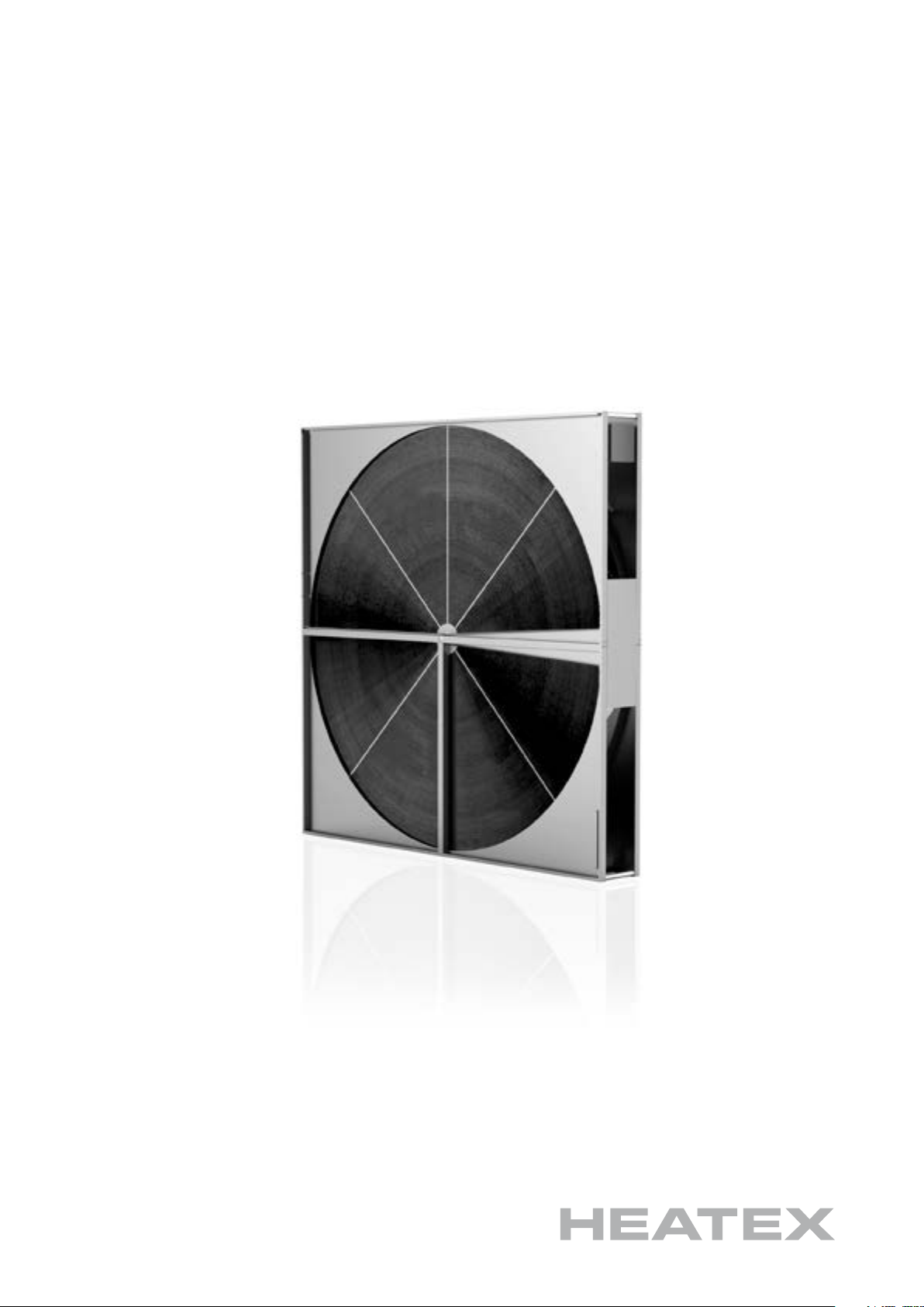
MODEL E
INSTALLATION
& MAINTENANCE
AIR-TO-AIR HEAT EXCHANGERS
Page 2

ENGLISH
ADDRESS AND CONTACT DATA
Bronsyxegatan 13
S-213 75 MALMÖ
Telephone: +46 410 710 500
[email protected]
www.heatex.com
DISCLAIMER
TEC-1301-V.8-201802-EN
Heatex AB
Sweden
Information in this document (including URL references and information from other external sources
referred herein) is subject to change without notice. Owing to continued product development, Heatex
reserves the right to introduce alterations in both design and prices without prior notice.
THIS DOCUMENT IS PROVIDED ”AS IS” WITH NO EXPRESSED OR IMPLIED
WARRANTIES WHATSOEVER, INCLUDING ANY WARRANTY OF MERCHANTABILITY,
NON-INFRINGEMENT, FITNESS FOR ANY PARTICULAR PURPOSE, OR OTHERWISE
ANY WARRANTY ARISING OUT OF ANY PROPOSAL, SPECIFICATION OR SAMPLE. ALL
LIABILITY, INCLUDING LIABILITY FOR INFRINGEMENT OF ANY PROPRIETARY
RIGHTS, RELATING TO USE OF INFORMATION CONTAINED OR REFERENCED IN
THIS DOCUMENT IS HEREBY EXPRESSLY DISCLAIMED.
COPYRIGHT NOTICE
All information and content included (whether directly or by reference) in this document, such as
text, graphics and images, is the property of Heatex AB, its subsidiaries, afliates, licensors and/or
joint venture partners. All rights are reserved.
No licenses, express, implied or otherwise to any intellectual property rights in this document are
granted by Heatex AB.
This disclaimer and copyright notice is subject to and governed by Swedish law.
Copyright © 2016
Heatex AB
2 (11) HEATEX MODEL E INSTALLATION & MAINTENANCE MANUAL
Page 3

TEC-1301-V.8-201802-EN
ENGLISH
DECLARATION OF INCORPORATION
Description and identication of the partly completed machinery:
Rotary heat exchanger model E with casing and with a drive unit.
The following essential requirements of EC Machinery Directive 2006/42/EC have been applied and
fullled:
1.1.2, 1.2.1, 1.2.3, 1.2.4.1, 1.2.4.2, 1.2.4.3, 1.2.6, 1.3.1, 1.3.2, 1.3.4, 1.3.7, 1.3.8, 1.3.8.1, 1.3.8.2, 1.4.1,
1.4.2.1, 1.4.2.2, 1.4.2.3, 1.4.3, 1.5.1, 1.5.2, 1.5.4, 1.5.5, 1.5.6, 1.6.1, 1.6.3, 1.7.1, 1.7.3, 1.7.4, 1.7.4.1,
1.7.4.2, 1.7.4.3
The relevant technical documentation has been compiled in accordance with Annex VII, Part B of
EC Machinery Directive 2006/42/EC. We undertake, in response to a reasoned request, to supply it in
electronic form to the market surveillance authorities within a reasonable period.
The party authorized to compile the technical documentation is:
Johan Gidner, R&D Manager
The partly completed machinery must not be put into service until the nal machinery into which it is
to be incorporated has been declared in conformity with the provisions of the Machinery Directive.
Malmö, 2015-06-18
3 (11)HEATEX MODEL E INSTALLATION & MAINTENANCE MANUAL
Page 4

ENGLISH
TEC-1301-V.8-201802-EN
CONTENT
1. GENERAL ____________________________________________________________________ 5
2. AT DELIVERY _________________________________________________________________ 5
2.1. Transport ___________________________________________________________________ 5
3. STORAGE ____________________________________________________________________ 6
4. INSTALLATION ________________________________________________________________ 6
5. ADJUSTMENTS _______________________________________________________________ 8
6. MAINTENANCE _______________________________________________________________ 8
6.1. Matrix ______________________________________________________________________ 8
6.2. Adsorption and Enthalpy Wheels ______________________________________________ 8
6.3. Powerbelt ___________________________________________________________________ 8
6.4. Round Belt __________________________________________________________________ 8
6.5. Brush Sealings _______________________________________________________________ 9
6.6. Special Sealings _____________________________________________________________ 9
6.7. Controller ___________________________________________________________________ 9
6.8. Application Limits ____________________________________________________________ 9
6.9. Troubleshooting ____________________________________________________________ 10
6.10. Conditions to Fulll the Hygiene Certication Requirements ______________________ 10
7. SUPPORT _____________________________________________________________________ 11
4 (11) HEATEX MODEL E INSTALLATION & MAINTENANCE MANUAL
Page 5
TEC-1301-V.8-201802-EN
1. GENERAL
A rotary heat exchanger with casing and drive is
“partly completed machinery” as dened in Directive
2006/42/EC. This product is delivered in compliance
with the Directive 2006/42/EC but when installed
in the complete machinery it is up to the installer to
make sure that the nal product complies with the
directive.
Special attention should be paid to sharp edges (risk
of cuts) and that when the wheel is rotating the rotating parts may cause injuries.
The surfaces of the drive motor and gear can be hot
and attention should be paid to the risk of burn injuries.
The sound level from the heat exchanger is less than
70 dB (A).
ENGLISH
2. AT DELIVERY
Before installation, the following should be checked:
• Check if there are any signs of transport
damage before accepting the goods.
• Has the right exchanger been delivered?
Check type, design, size and options.
1
• How is the exchanger to be positioned?
• In case of any damage, please report this in
writing by email as soon as possible.
2.1. Transport
• Always transport the exchanger vertically.
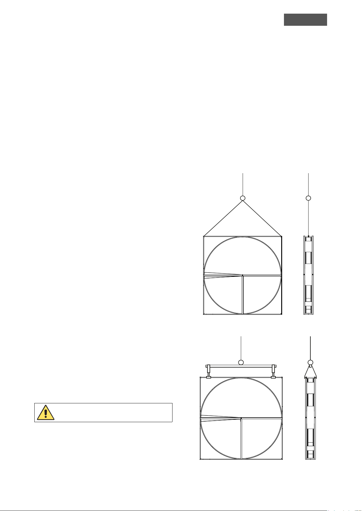
• Lift the exchanger in the upper two corner
distance pipes according to Picture 1. If the
casing is covered, please lift at the gables
according to Picture 2.
• It is important that all transport and handling is
carried out by qualied staff.
Picture 1. Lift the casing at the corner distance pipes.
All transport and handling shall be carried out by
qualied staff.
_________________________________________
1
Please note that for diameters between 500 mm (19.69”) and
900 mm (35.43”) the controller of the variable speed drive unit
will be delivered separately.
Picture 2. If the casing is covered, lift the casing at the
gables.
5 (11)HEATEX MODEL E INSTALLATION & MAINTENANCE MANUAL
Page 6
ENGLISH
TEC-1301-V.8-201802-EN
3. STORAGE
Aluminum wheels are sensitive for corrosion, epoxy
wheels to sunlight and hybrid, as well as adsorption
wheels, to moisture. Please make sure that you store
the wheels to avoid the conditions described above.
Furthermore, the unit is to be placed on a horizontal
and even surface. Please note that an uneven surface
can warp the rotor and affect the factory adjustments.
Always make sure that the heat exchanger is supported and secured during transport, handling, storage
and installation so it cannot fall over and cause damage or injuries.
Heat exchanger may fall over if not secured.
Please observe that there may be sharp edges and a
risk for cuts so we recommend that gloves should be
used when the heat exchanger is handled.
Use gloves when handling the
heat exchanger.
Always make sure that the storage temperature is kept
above 0°C (32°F).
Rotors without casing (Model O), must be stored fully
supported lying horizontally (as delivered) or hanging
by their shaft.
4. INSTALLATION
• When designing the air handling unit and/
or duct system, the system designer needs to
make sure it is possible to remove/pull out the
heat exchanger for inspection, maintenance,
service, cleaning and disinfection. Furthermore,
the system designer needs to consider enough
space inside and outside of the system to make
sure that it is possible to remove/pull out the
heat exchanger.
• For bigger heat exchanger units it is required
to add doors or hatches on all sides in the
air-handling unit and/or duct system making
it possible to access the heat exchanger for
inspection, maintenance, service, cleaning and
disinfection.
• In case condensate is present, it is required
by the designer of the air handling unit and/
or duct system, to design and install a condensation tray according to the norm VDI 6022,
chapter 4.3.16
• The casing is a built–in casing, which means
that it needs to be attached to the Air Handling
Unit (AHU).
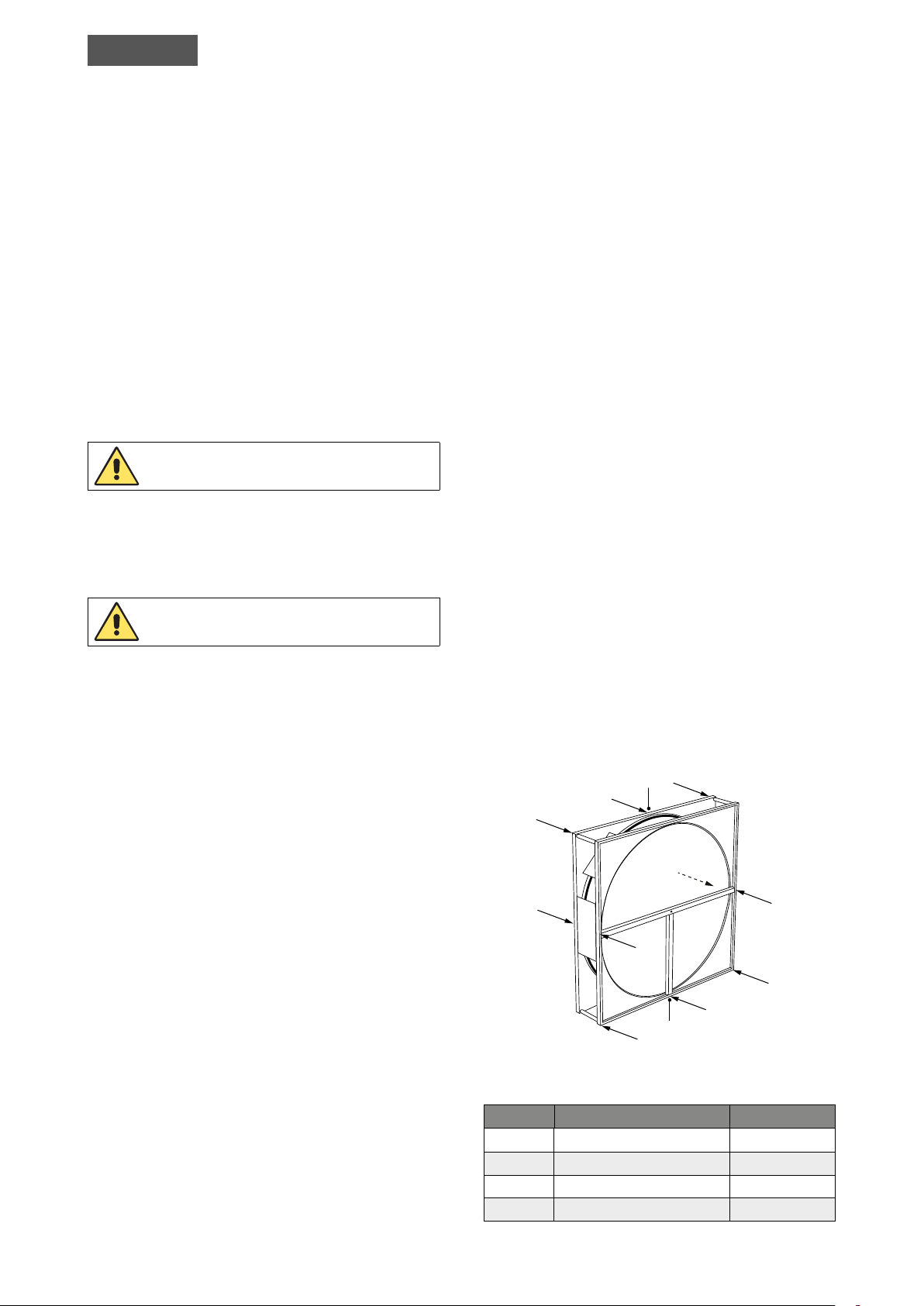
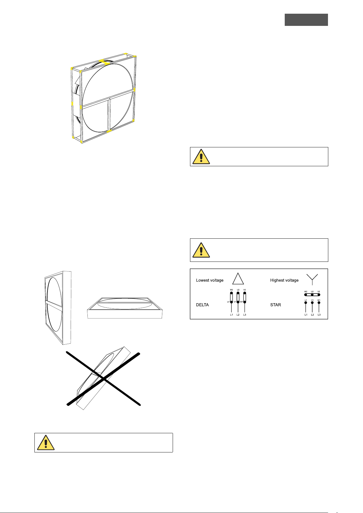
• To know where to fasten the casing in the
AHU, please refer to the force schedule on
Picture 3 and the fastening points in Picture 4.
• Place the rotor on a horizontal surface since an
uneven surface can warp the rotor and affect
the factory adjustments.
4
1
1
1
1
1
2
2
3
2
2
2
Picture 3. Force schedule.
Force Direction of force Ø 0-2500
1 Against the airow 0.7 KN
2 Against the airow 0.7 KN
3 Vertically up 10.5 KN
4 Vertically down/up 0.75 KN
6 (11) HEATEX MODEL E INSTALLATION & MAINTENANCE MANUAL
Page 7
TEC-1301-V.8-201802-EN
ENGLISH
• Avoid angular ow since this can affect the
rotation and drive of the wheel. Heatex AB
recommends the airow to be perpendicular to
the rotor.
• The rotor is designed for counter ow only;
co-current ow will decrease efciency and
reduce the rotors self-cleaning ability.
• Prior to initial operation, please make sure no
objects are blocking the rotors movement. The
rotor should move evenly and smoothly around
its shaft.
Picture 4. Fastening points.
• Make sure that the front- and back plates of
the casing are installed perpendicular to the
horizontal bottom surface. If not the casing
may interfere with the movement of the rotor
wheel.
• In case of horizontal rotors, support is needed
for the frame and center beam. Also, check
that rotor is ordered and manufactured as a
horizontal rotor. Rotor may only be installed
either in a vertical or a horizontal position
according to design, not tilted unless approved
by Heatex.
Placing the unit on an uneven surface
may warp the rotor.
• Drive motor if delivered with controller is
pre-wired and 230V should just be wired to
the controller. Constant speed motors are
without wiring. It is important that all electrical
work is carried out by qualied staff. Please
see enclosed documentation and/or wiring
Picture 6.
IMPORTANT!
All electrical work must be carried
out by qualied staff.
Picture 6. Wiring diagram constant drive Δ/Y 220/380V.
Picture 5. Rotor positions.
In case of a horizontal rotor, support is needed for
the frame and center beam.
• The motor and the controller should be easily
accessible for service and maintenance.
• If the unit is delivered with a variable speed
drive, read the corresponding controller
documentation.
• Pressure difference and pressure drop should
under no circumstances exceed the limits.
Please refer to Application Limits for further
information.
• The customer needs to make sure that the fans
are placed in a way that an evenly distributed
force is assured.
7 (11)HEATEX MODEL E INSTALLATION & MAINTENANCE MANUAL
Page 8
ENGLISH
TEC-1301-V.8-201802-EN
5. ADJUSTMENTS
• If necessary, adjust the brush sealing to
minimize leakage.
• The special sealing does not need any
adjustments.
• If the belt slides adjust belt tension.
• The round belt should have a tension of 3%.
Powerbelt should have a tension of 1-2% (i.e.
belt should be 1-2% shorter than the length
it travels). For adjustments, see maintenance
instructions below.
6. MAINTENANCE
6.1. Matrix
To secure the function and performance, the face of
the rotor has to be inspected regularly for dust and
dirt. In most cases, the rotor is self-cleaning due to
counter ow and rotation of the matrix and this
makes manual cleaning unnecessary. If the self-cleaning is insufcient dirt or/and dust can appear in the
matrix.
The enthalpy wheel properties are obtained by a combination of adsorption material consisting of silica
gel coated aluminum and a corrugated aluminum
strip. Just as for the adsorption wheel, a small amount
of surplus material might leave the matrix during the
rst usage.
6.3. Powerbelt
The Powerbelt is subject to natural stretching which
may require shortening of the belt. Tension of the
belt must be checked after the rst 24-48 hours in
operation to secure the rotational function of the
wheel.
The belt is made of links that can easily be added or
removed without any tools. By just twisting the belt, it
is possible to open it and remove links to shorten the
belt until correct length and belt tension is obtained.
Belt tension should be 1-2% (i.e. belt length 1-2%
shorter than travelled length). For Powerbelt remove
one link per meter belt to get correct tension.
6.4. Round Belt
Depending on the degree of soiling it is recommen-
ded to use following cleaning:
1. For only a small amount of easily removable
dirt, Heatex recommends to use a vacuum
cleaner.
2. For heavier dirt it is also possible to use
compressed air but with caution.
3. Firmly attached dirt in the rotor is easiest
removed by using hot water and a mild
detergent. The mild detergent may be removed with high-pressure water cleaner with the
nozzle placed 50-100 mm from the matrix.
4. If required, Heatex recommends disinfection
with the substance known as LIV +45 (isopro-
panol based substance).
6.2. Adsorption and Enthalpy Wheels
The adsorption material is aluminum coated with
silica gel or molecular sieve 3Å coating. There is a
small amount of surplus material that might leave the
matrix during the rst usage. This will NOT affect the
hygroscopic properties. The excess powder is harmless and easy to remove using a vacuum cleaner.
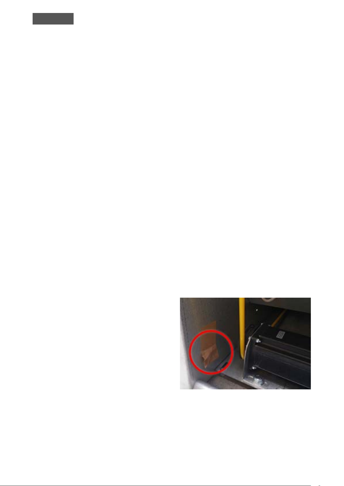
In addition, the round belt may need adjustment
during its lifetime. When delivered from factory the
belt is welded together. If adjustment is needed the
belt must be cut, shortened and joined together again
with a special joining pin, which is attached on the
casing (see Picture 7). Belt tension should be 3%.
Picture 7. Joining pin.
8 (11) HEATEX MODEL E INSTALLATION & MAINTENANCE MANUAL
Page 9
TEC-1301-V.8-201802-EN
ENGLISH
6.5. Brush Sealings
Tightness between brush sealings and casing has to
be checked during inspection. The brush sealings are
easily adjusted by unscrewing the screws and moving
the brush sealing into the right position.
6.6. Special Seals
• The tightness of the special sealing is adapted
at the Heatex factory and is not possible to
readjust on site. The new seal design makes it
possible for Heatex to deliver a tight seal to
every customer despite the conditions.
• Yearly inspections are needed to verify the
conditions of the seals.
• In case it is needed, replacement can be ordered
from Heatex.
6.7. Controller
For further information regarding rotary heat exchanger equipped with controller, please see corresponding controller instructions.
Maximum and recommended pressure drop as well as
differential pressure for rotary heat exchanger:
• Pressure drop max 300 Pa (1.2” WC) up to
outer diameter 1600 mm (62.99”) and pressure
drop max 250 Pa (1” WC) up to outer diameter
2500 mm (98.43”), even during start up and
maintenance.
• Recommended pressure drop 100-200 Pa
(0.4-0.8” WC) (normal operation).
• Differential pressure max 600 Pa (2.4” WC).
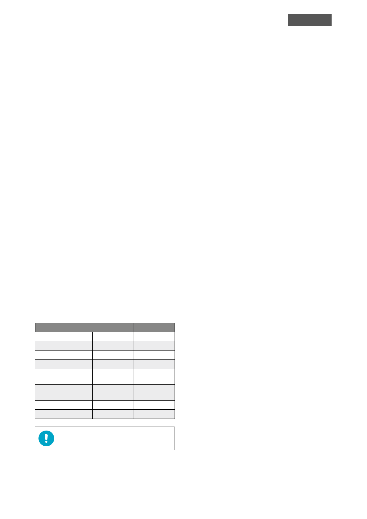
6.8. Application Limits
Recommended temperature limits for rotary heat
exchanger Model E are -40°C (-40°F) to +65°C (149°F).
It is however important not to exceed the temperature
limits on mounted components:
Component Min Max
Bearings -40°C (-40°F) 110°C (230°F)
Yellow belt -30°C (-22°F) 66°C (150°F)
Power belt -40°C (-40°F) 110°C (230°F)
Constant motor -10°C (14°F) 40°C (104°F)
Varimax step motor
and control
OJ step motor and
control with modbus
Standard seals -25°C (13°F) 90°C (190°F)
Special seals -25°C (13°F) 90°C (190°F)
NOTE! The temperature inside the casing is app-
roximately the mean temperature of supply and
-30°C (-22°F) 45°C (113°F)
-40°C (-40°F) 40°C (104°F)
exhaust air temperatures.
9 (11)HEATEX MODEL E INSTALLATION & MAINTENANCE MANUAL
Page 10

ENGLISH
TEC-1301-V.8-201802-EN
6.9. Troubleshooting
If the rotary heat exchanger does not rotate properly, please follow these steps to solve/locate the problem.
1. If the motor runs properly, please jump to step 5.
2. If there is a controller installed please check controller technical specications, chapter trouble shooting.
3. If there is a constant drive installed: Please check that the drive is correctly connected. Note that all electri-
cal maintenance and installation must be performed by qualied personal.
4. The position of the pulley should be placed as near the center of the rotor as possible.
5. Disconnect the belt. Is the motor running correctly?
6. If the belt is sliding, please tighten the belt according to maintenance instruction.
7. Rotate the wheel by hand in the indicated direction (belt disconnected from the motor). Is it possible to
smoothly rotate the wheel or does the wheel interact with the casing? If there is excessive friction between
the wheel and the casing (making it hard to rotate), please locate the position.
8. Make sure the connected ducts do not press on the casing making it squeeze against the wheel. Make sure
the diagonal measures of the casing side where the motor is positioned are equal.
9. If the rotor with special seals doesn´t rotate, please follow these steps. First, before turning on the drive
system, rotate the wheel manually a couple of times in the same direction that it is supposed to rotate. The
brushes of the seal need to adapt to the rotating direction.
Then, turn on the drive and make sure that the direction of rotation is the same as when the wheel was
rotated manually.
6.10. Conditions to Fulfill the Hygiene Certification Requirements
• Purge sector is required in order to make sure that less carry-over than 3% is reached.
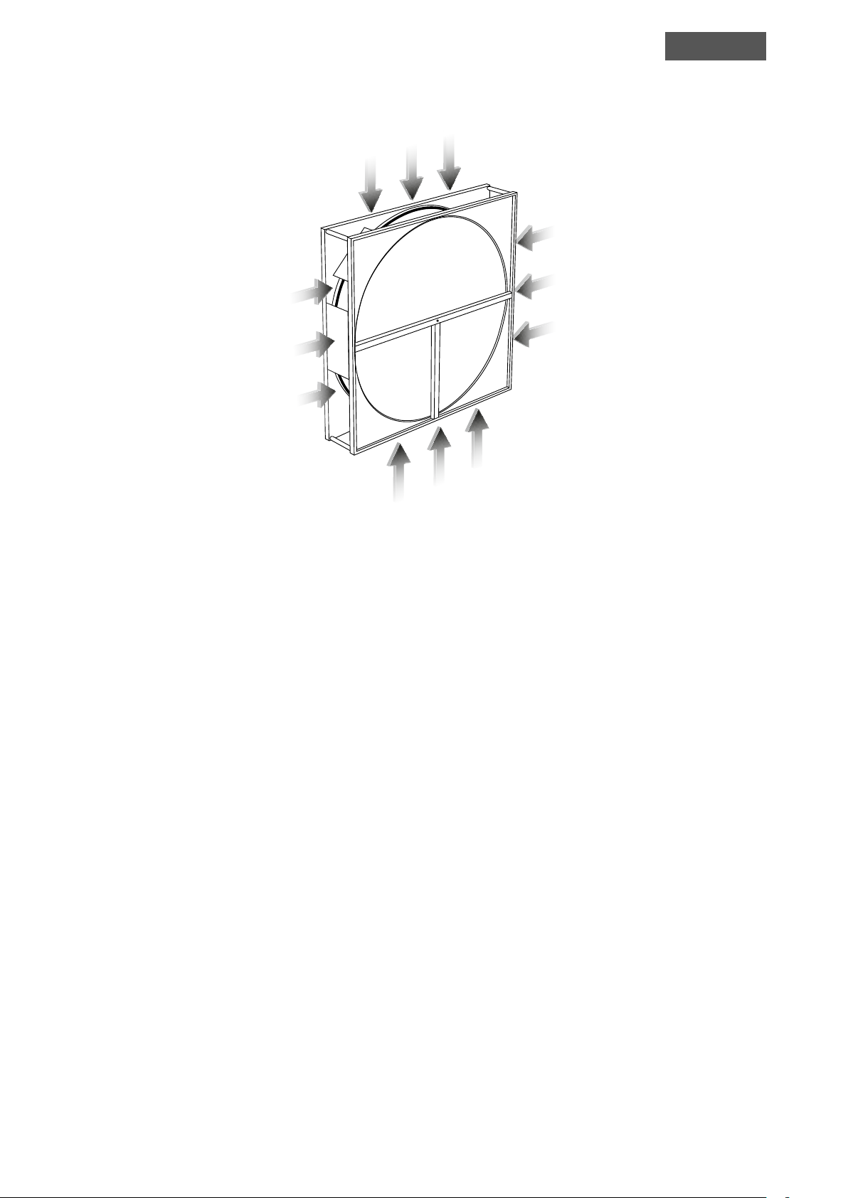
• The AHU needs to be designed with hatches or openings towards all 4 open sides of the rotary heat ex-
changer. The heat exchanger itself has all 4 sides open according to the picture 8.
• All surfaces inside and outside of the rotor casing, especially the bottom surface and around the motor
should be reachable for maintenance, cleaning and disinfection. Meaning that the openings or hatches
mentioned in the item above need to be of sufcient size to fullling the cleaning and disinfection requirements.
• The AHU needs to be designed in such a way that the rotary heat exchanger is possible to slide out for
cleaning and disinfection.
• Cleaning and disinfection of the heat exchanger should be done in accordance with Heatex cleaning and
disinfection instructions with the cleaning and disinfection substances prescribed by Heatex (see Maintenance chapter).
• When condensation is present, the AHU installer needs to make sure that condensation trays are installed
beneath the heat exchanger. These trays need regular inspection, cleaning and disinfection.
• The trays should be designed and installed with sufcient drainage in accordance with the hygiene standard
VDI 6022, chapter 4.3.16.
• The heat exchangers are not certied for installation in exhaust classes ETA 3 and ETA 4 according to EN
13779 (09/2007).
10 (11) HEATEX MODEL E INSTALLATION & MAINTENANCE MANUAL
Page 11
TEC-1301-V.8-201802-EN
ENGLISH
Picture 8. All 4 sides are open on the heat exchanger. The AHU designer and installer need to have openings or
hatches on all of these 4 sides in the AHU for easy access during maintenance, cleaning and disinfection of the heat
exchanger.
7. SUPPORT
For questions or information regarding this product, please communicate your order number and product code
along with your message.
Heatex is available for support during ofce hours: 8 am – 4.30 pm (GMT +1) on weekdays.
11 (11)HEATEX MODEL E INSTALLATION & MAINTENANCE MANUAL
 Loading...