

Heater Craft 900 User Manual
2011-12 RZR Heater
Instructions (2878366)
6672 Boekel Road, Rathdrum | (208) 687-4400 | www.heatercraft.com

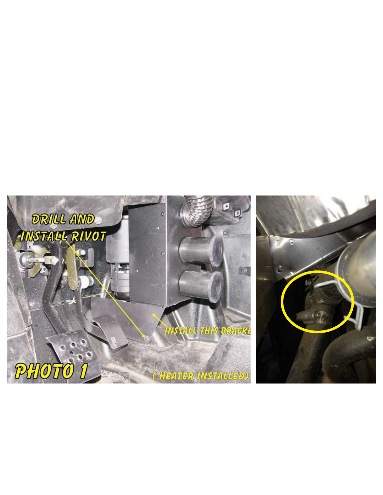
NOTE: This heater unit installs below the center of the dash and fits tightly between the powersteering cover
and glove box. The holes in the firewall must be properly located to insure theunit fits in this space. (Photo 1)
NOTE: Check engine coolant level often until all of the air is removed from the system.
1. Lift the front of the vehicle and secure. Remove the passenger side wheel. Drain the coolant system by
removing the lower radiator hose. Retain the coolant in a clean container for reuse.
2. Remove the seats, center consol (floor pan) and rear panel to expose the engine front. Remove the
thermostat housing (with hose attached) from the engine. Install the adaptor, O-ring, thermostat and
housing as shown in Photo 2 and Diagram “A” using the longer bolts supplied.
2.1. For 900 RZR only Remove the seats, center console (floor pan) and rear panel to expose the engine
front. Cut the 1.00” coolant Supply line TO THE THERMOSTAT HOUSING shown in RZR 900 PHOTO
1(6253) and install provided ‘T’ fitting with hose clamps.
3. Connect the ¾” hose to the adaptor outlet and route the hose under the floor forward to the space
behind the radiator. Secure the hose away from drive shaft and sharp points. Replace the center consol
(floor pan).
3.1. For 900 RZR only Connect the ¾” hose to the T-Fitting outlet and route the hose under the floor
forward to the space behind the radiator. Secure the hose away from drive shaft and sharp points. Replace
the center consol (floor pan).
4. Locate the (2) existing ½” holes in the firewall center (above the accelerator pedal).Align the Hose
template with the holes and cut the 1 3/8” holes for the grommets and hoses. Install the grommets.
5. You will need to install the remaining mount bracket onto the heater. Remove the screws from the bottom
of the heater and install the bracket as shown in Photo 1.
6. Lube the grommets and short hose pieces on heater. Position the heater in the vehicle and feed the hoses
thru the grommets in the firewall. Use the u-bolts and nuts to hang the heater from the dash support tube.
(Photo 3) Drill a 5/16” hole thru the floor pan using the hole in the lower bracket as a guide and install the
plastic rivet. (Photo 1)
7. (Photos 4 & 5) With the flow arrow on the valve pointing towards the heater install the valve on the hose
coming from the driver side of the heater. Do not tighten. Cut the hose that you installed in step 3 coming
from the engine to the proper length and connect to the valve. Do not tighten. Locate the cable position
in the dash (Photo 5) and drill a 3/8”hole. Install the cable in the dash and route thru the firewall (see hose
template) to the valve. With the valve off and the control knob pushed in (off) connect the cable to the
valve. Position the valve and hoses clear of obstructions so that the valve operates properly. Tight the
hoses to the valve. Apply the piece of trim to the u-shaped brace and secure the hoses and valve to the
vehicle using wire ties.
8. Reinstall the lower radiator hose. Cut the lower radiator hose 3 inches from the tee and install the 1x1x3/4”
Tee. Connect the hose from the passenger side of the heater to this Tee. Tighten all clamps. (Photo 6)
9. Use the template to drill and cut out the dash for the defrost vent. Check for clearance under the dash
before drilling or cutting. Mount the defrost vent using the hardware provided. Connect the vent hose to
the vent. Route the duct hose to the heater and connect to the top vent.
10.Determine a suitable place in the dash for the blower switch (see Photo 5). Use the template to cut the
hole in the dash. NOTE: The (3) wire bundle with spade connectors must reach the back of the switch.
Install the switch in the dash with the 3 wires connected as follows: Viewed looking at the back left side
of switch: Yellow to top, Red to middle and Orange to bottom. The 2 wire bundle (Red & Black) supplies
the power. The black wire is bolted to a hole in the dash support above the heater using a ¼” x ¾” bolt
and nut. Connect the Red wire with the bullet terminal to the accessory bullet terminal in the wire bundle
leading to the accessory outlet in the dash. Secure all wiring with wire ties as needed. With the key on
operate the switch to make sure the blower operates.
11.Check and tighten all hose clamps. Check hose routing and secure away from all moving parts.
12.Remove the radiator cap and pull the heater control knob to the on position. Fill the radiator with coolant.
Start and run the engine for a while filling the radiator as the air bleeds out (about 3 minutes). Replace
the cap, check for leaks and run the engine for several minutes. Check the heater function by turning the
blower on and feeling for warm air. Turn the engine off and allow time to cool. Refill radiator as necessary.
13.Replace rear panel and seats.
14.Replace the warning decal with the new one provided in the area forward of the defrost vent.11.Check
and tighten all hose clamps. Check hose routing and secure away from all moving parts.
12.Remove the radiator cap and pull the heater control knob to the on position. Fill the radiator with coolant.
Start and run the engine for a while filling the radiator as the air bleeds out (about 3 minutes). Replace
the cap, check for leaks and run the engine for several minutes. Check the heater function by turning the
blower on and feeling for warm air. Turn the engine off and allow time to cool. Refill radiator as necessary.
13.Replace rear panel and seats.
14.Replace the warning decal with the new one provided in the area forward of the defrost vent.
Photo 1 900 ONLY
 Loading...