


PRO3
Installation and
Operations Manual
Bulletin H-IM-PSM May 2008 Part Number 25008001
PRO3 Side Mount
Packaged Refrigeration System
Table of Contents
Inspection............................................................................3
Installation Requirements .................................................3
Recommended Unit Placement
FIGUR E 1: System Space Requirements | Back View
FIGUR E 2: System Space Requirements | Side View
Access Requirements .........................................................3
Condensing Unit Section (Exterior of box)
FIGUR E 3: Access Requirements | Top View
Evaporator Section (Interior of box)
Installation Procedures ..................................................4-7
FIGUR E 4: Cutout Location
FIGUR E 5: Cutout Dimensions | Small Cabinet
FIGUR E 6: Cutout Dimensions | Large Cabinet
FIGUR E7: Plug Detail
FIGUR E 8: Plug Detail | Small Cabinet
FIGUR E9: Plug Detail | Large Cabinet
Rigging
FIGUR E10: Rigging Holes
FIGUR E 11: Rigging Holes | Front View
Mounting
FIGUR E12: Mounting Holes | Side View
FIGUR E 13: Mounting Holes | Front View
FIGUR E 14: Mounting Holes | Top View
Electrical Connection
Refrigeration Sequence of Operation ...............................7
TABLE 1 Model PST | Default Temperature Control Settings
Cooler Temperature Control
Coolers: Air-defrost Operation
Cooler with Electric Defrost and Freezer Temperature/
Defrost Control
Cooler with Electric Defrost and Freezer Sequence of
Operation
Programming Electronic Controller ............................ 8-16
Dixell Electronic Controller (XR40CX and XR60CX)
Front Panel Commands ..................................................................8
Use of LEDs...........................................................................................8
Max. & Min. Temperature Memorization: .................................9
How to See the Min. Temperature
How to See the Max. Temperature
How to Reset the Max. & Min. Temperature Recorded
Main Functions: .................................................................................9
How to see the set-point
How to change the set-point
How to start a manual defrost
How to change a parameter value
Installation and Operations Manual
The Hidden Menu .............................................................................9
How to Enter the Hidden Parameters
How to Move a Parameter from the Hidden Menu
How to Lock the Keyboard
The Continuous Cycle
The On/O Function
Parameters .................................................................................10-11
Regulation
Display
Defrost
Fans (XR60CX ONLY)
Alarms
How to use the Hot Key ................................................................11
How to program a Hot Key from the Instrument
Alarm Signals ...................................................................................12
Alarm Recovery
Other Messages ..............................................................................12
Technical Data .................................................................................12
Connections .....................................................................................13
Service Information..........................................................13
Maintenance
System Standard Maintenance Guidelines
Drain Pan Removal..............................................................................14
FIGURE 15: Drain Pan Removal | View A
FIGURE 16: Drain Pan Removal | View B
Wiring Diagrams ......................................................... 15-18
DIAGRAM 1 High Temperature Cooler | Air Defrost | Large Cabinet
DIAGRAM 2
DIAGRAM 3 Freezer and Medium Temperature Cooler | Electric Defrost | Small Cabinet
DIAGRAM
Performance, Capacities and Specications ..................19
TABLE 2 Cooler Application | Air Defrost | BTUH at 95°F ambient
TABLE
TABLE
TABLE
Dimensions ................................................................. 20-21
DIAGRAM 5 Dimensions | Small Cabinet: 1-fan | Top view
DIAGRAM
DIAGRAM
DIAGRAM
DIAGRAM
DIAGRAM
Replacement Parts by InterLink .....................................22
TABLE 6 Replacement Parts List
Warranty Statement ........................................................23
High Temperature Cooler | Air Defrost | Small Cabinet
4 Freezer and Medium Temperature Cooler | Electric Defrost | Large Cabinet
3 Cooler Application | Electric Defrost | BTUH at 95°F ambient
4 Freezer Application | Electric Defrost | BTUH at 95°F ambient
5 Specications
6 Dimensions | Small Cabinet: 1-fan | Side view
7 Dimensions | Small Cabinet: 1-fan | Back view
8 Dimensions | Large Cabinet: 2-fan | Top view
9 Dimensions | Large Cabinet: 1-fan | Side view
10 Dimensions | Large Cabinet: 1-fan | Back view
2
© 2008 Heatcraft Refrigeration Products LLC
PRO3 Side Mount Packaged Refrigeration System
Leave this area unobstructed
Leave these areas
unobstructed
24"
4.00
18"18"
24"
36"
8"
Inspection
1. Each shipment should be carefully checked against the bill
of lading.
2. The shipping receipt should not be signed until all items listed
on the bill of lading have been accounted for.
3. Check packaging for signs of damage.
4. Any shortage or damages should be immediately reported to
the delivering carrier.
5. Damaged material becomes the delivering carrier’s
responsibility, and should not be returned to the manufacturer
unless prior approval is given to do so.
6. All units are shipped on heavy skids and enclosed in open
crating. Generally, it is advisable to bring the unit as close to
its nal location as possible before removing crating.
7. When unpacking the system, care should be taken to
prevent damage.
8. Avoid removing the shipping base until the unit has been
moved to the nal destination.
Installation Requirements
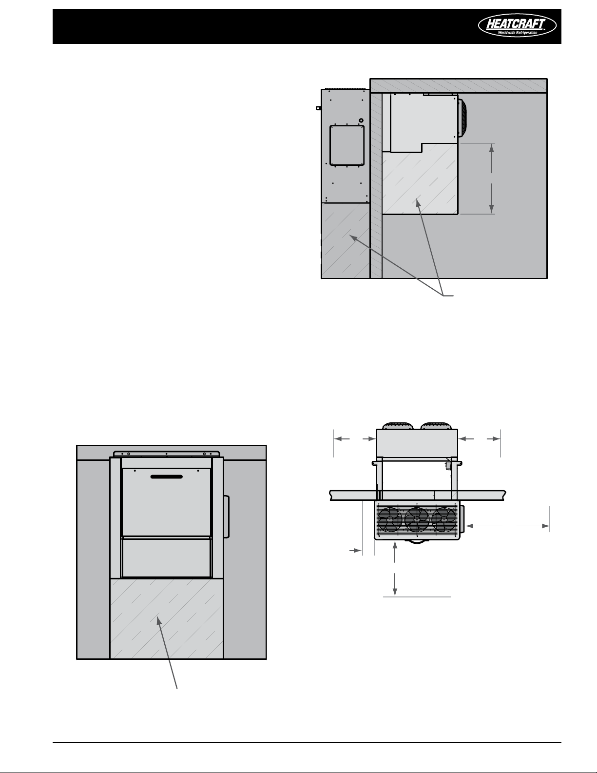
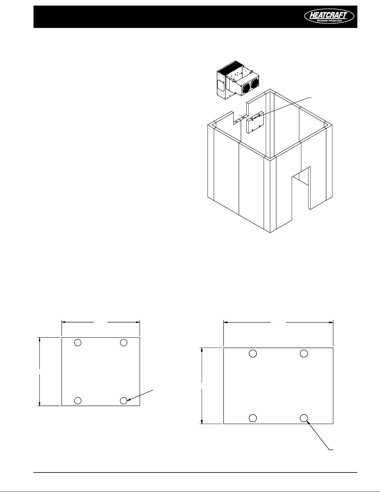
Recommended Unit Placement
1. Ensure that the structural integrity of the box can withstand
the weight of the side-mounted equipment.
2. The air pattern must cover the entire room
3. Location of aisles, racks, etc. must be known
4. For space requirements,
see FIGURES 1 and 2
2: System Space Requirements | Side View
FIGUR E
Access Requirements
Condensing Unit Section (Exterior of box)
Provide adequate access space (minimum 36") on the right side of
the unit for electric box clearance. The front of the unit should have
a minimum of 24" clearance for compressor and fan motor service.
The left side of the unit should be a minimum of 8" clearance.
FIGUR E
3: Access Requirements | Top View
FIGUR E 1: System Space Requirements | Back View
Evaporator Section (Interior of box)
The front of the evaporator should have no obstructions since this
is the leaving airside of the evaporator. There should also be no
obstructions under the evaporator. A minimum of 8" clearance should
be held on each side of the evaporator for drain pan removal.
PRO3 Side Mount Packaged Refrigeration System Installation and Operations Manual, May 2008 3
Installation and Operations Manual
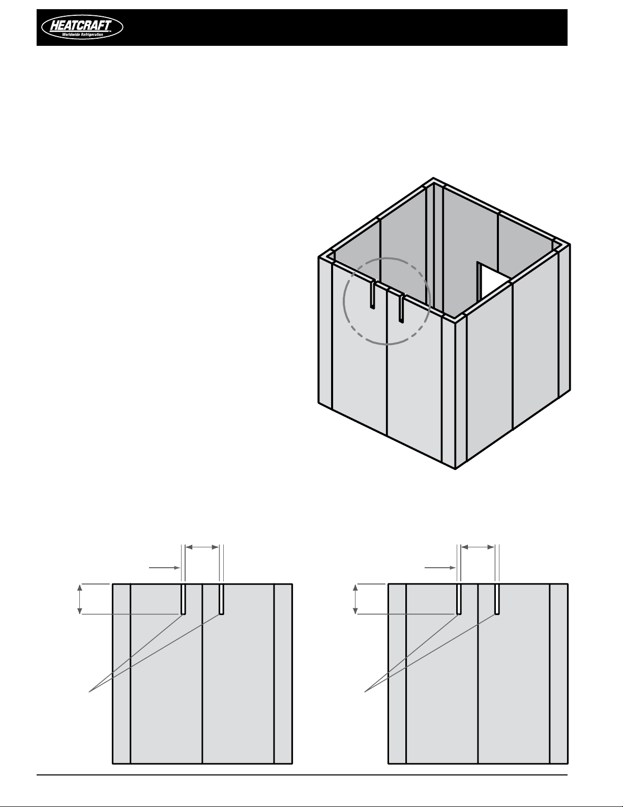
2.62" TYP
20.25" TYP
22.75" TYP
CUTOUTS
2.62" TYP
20.25" TYP
28.75" TYP
CUTOUTS
Installation Procedures
NOTE: Installation and maintenance to be performed only
by qualied personnel who are familiar with local codes and
regulations and are experienced with this type of equipment.
CAUTION: Make sure all power sources are disconnected
before any service work is done on units.
A.) Inspect packaging/unit for shipping damage
B.) Review the space and location requirements provided for your
method of installation.
C.) Follow installation instructions listed in method #1 or #2
Installation Method #1
Top Installation (See FIGURES 4, 5 and 6)
This installation method is the recommended installation method
in applications where it is feasible.
In order to install a unit using this method, you will need to provide
cutout slots for the “arms.” The unit should be placed on the wall
prior to setting and securing the roof of the box.
Please use the following guidelines when completing the installation
in this manner.
1. You will need to provide nished slots with the appropriate
dimensions in the box wall.
2. The slots can straddle a seam but they should not be on a seam.
See FIGURE 4.
3. The cut-out sections should not be placed in a location where
they would interfere with any cam locks.
4. It is preferred that a cam lock be placed in between the cutouts
to give additional support
See FIGURES 5 and 6.
5. The unit will need to be lifted to the appropriate height and
inserted into the open slots. The bottom of the unit should
be temporarily supported during the remainder of the installation
process (no portion of the unit should be supported by the
bottom of the evaporator section as this WILL cause damage to
the drain pan).
6. Set and secure the roof of the box and rmly attach the unit to
the box and carefully seal all seams and penetration points.
FIGUR E 4: Cutout Location
FIGUR E 5:
Cutout Dimensions | Small Cabinet
CAUTION: Do not support any portion of the unit by the
drain pan.
FIGUR E 6: Cutout Dimensions | Large Cabinet
4
PRO3 Side Mount Packaged Refrigeration System
SEE PLUG DETAIL
29.00
20.07
CAMLOCKS
4 PLACES
20.00
23.00
CAMLOCKS
4 PLACES
Installation Method #2
Side Installation (See FIGURES 7, 8, and 9)
This installation method is intended for applications that have
height restrictions that do not allow the unit to be installed from
above (see method #1) and installations into pre-existing boxes
where it is impractical to remove the roof.
In order to install a unit using this method, you must provide an
additional “plug” section of the box to ll in the open space between
evaporator arms after installation. This section should contain cam
locks to anchor it in place.
Please use the following guidelines when completing the installation
in this manner.
1. Provide a nished opening with the appropriate dimensions
from FIGURE
2.
The cut-out section should not be placed in a location where it
would degrade the structural integrity of the box (should not
interfere with cam locks)
3. The unit will need to be lifted to the appropriate height and
inserted into the open slot. The bottom of the unit should be
temporarily supported during the remainder of the installation
process (no portion of the unit should be supported by the
bottom of the evaporator section as this WILL cause damage to
the drain pan).
4. You should use cam locks to re-connect the “plug” section after
installing the unit, rmly attach the unit to the box and carefully
seal all seams.
8 or 9.
FIGUR E 7: Plug Detail
FIGUR E 8:
Plug Detail | Small Cabinet
FIGUR E 9:
Plug Detail | Large Cabinet
PRO3 Side Mount Packaged Refrigeration System Installation and Operations Manual, May 2008 5
Installation and Operations Manual
Mounting
holes
Front panels
removed
for clarity
Mounting holes
Mounting holes
Top not shown
for clarity
Mounting holes
Rigging holes
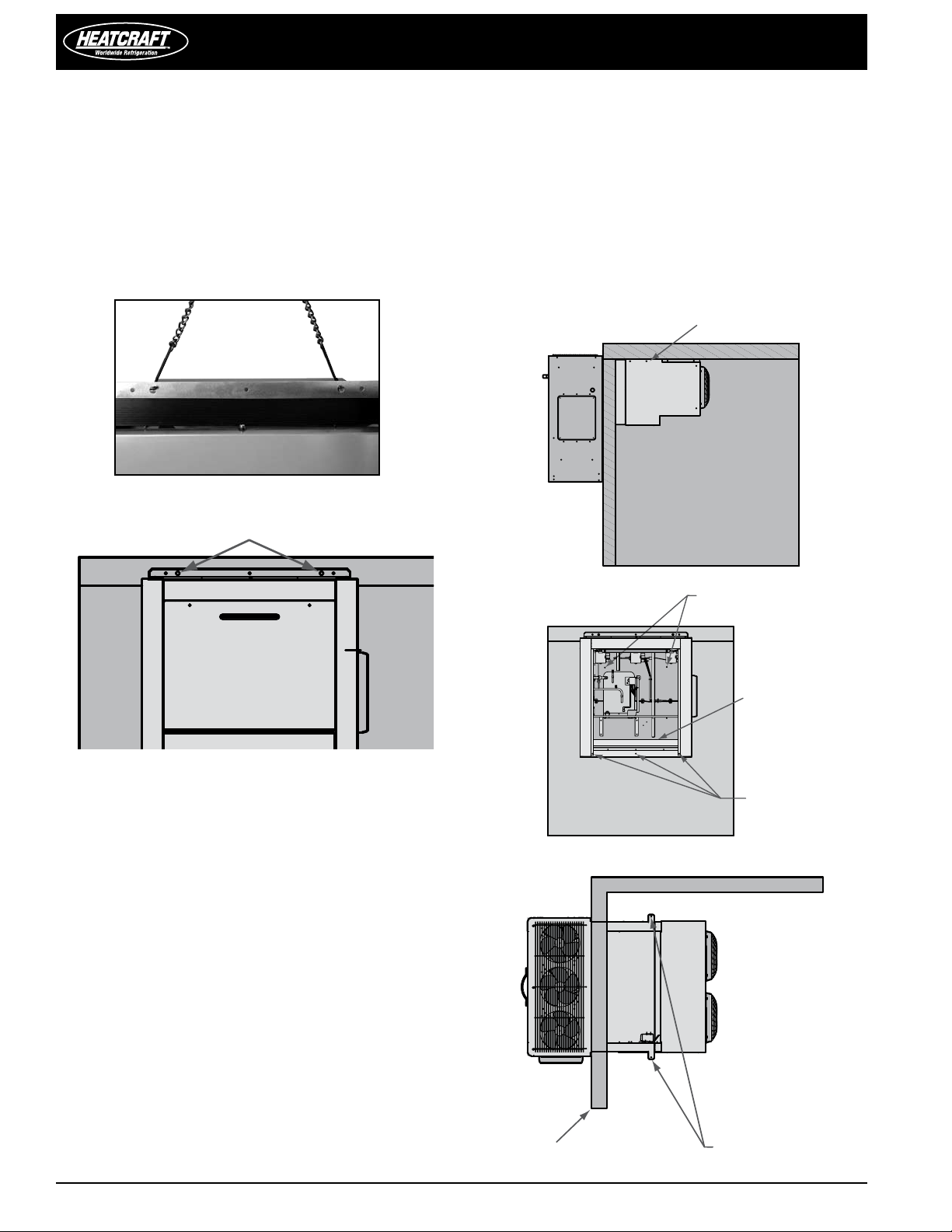
Rigging
CAUTION: Avoid contact with sharp edges and coil
surfaces. They are a potential injury hazard. Wear gloves
during moving and rigging.
Caution should be exercised when moving these units. To prevent
damage to the unit housing during rigging, cables or chains used
must be held apart by spacer bars. Rigging holes are provided on
all models. See FIGURES 10 and 11.
FIGUR E 10: Rigging Holes
FIGUR E 11: Rigging Holes | Front View
4. Ensure that the condensing unit airow is not obstructed after
removing the temporary support.
5. Do not obstruct the evaporator airow with shelving. The area
below the evaporator should be left completely open.
6. Connect unit to power supply through knock-out provided
above electrical box using all local wiring codes.
7. Apply power to unit. All controls are preset to factory default
settings. See Table 1 (next page).
8. Check the unit for proper operation.
FIGUR E 12: Mounting Holes | Side View
Mounting
The system requires two through-bolts to be used to connect to
the roof panel. A minimum of four through-bolts should be used to
connect to the side panel of the box. The opposite side of the box
should be reinforced with wood or metal to prevent the bolts from
pulling through the panel. See FIGURES 12, 13 and 14 for locations.
Through bolts should be insulated or non-conductive to prevent
sweating. All penetrations to the box should be caulked to prevent
moisture from entering the box.
1. Install two through bolts to secure the unit to the wall. The inside
of the box should be reinforced with wood or metal for proper
when mounting of the unit to the box with through bolts.
2. Install and secure the roof of the box. Inside the box,
provisions have been made to secure the evaporator section
to the roof panel with through bolts.
3. The area between the evaporator section and the roof
panel should be caulked to meet NSF codes. In addition, the
openings where the unit was lowered into the box panel
should be caulked to prevent any inltration from the outside
area into the box.
FIGURE 13: Mounting Holes | Front View
FIGURE 14: Mounting Holes | Top View
6
PRO3 Side Mount Packaged Refrigeration System
Electrical Connection
1. Refer to all local codes for proper connection.
2. A knock-out is provided for 1" conduit on the side of the
condensing unit section above the electrical box. See FIGURE 12.
3. Wire will be brought into the electrical box through the
bottom of the electrical box and connected to the top of the
contactor.
Refrigeration Sequence of Operation
1. Power is provided to the temperature control, compressor
contactor and cooler evaporator fans.
2. The temperature controller closes and energizes the
compressor contactor, starting the compressor, evaporator
and condenser fan(s).
3. When the system reaches the desired box temperature, the
temperature control will de-energize the compressor contactor.
Evaporator fans will continue to operate at this point.
4. When the xture temperature rises above the set point
and minimum o-time has elapsed, the temperature control
will close and re-energize the compressor contactor.
Coolers: Air-defrost Operation
Air defrost units are pre-programmed for 4 defrost per day. These
periods are reprogrammable. When the coil temperature reaches
38°F, the control will terminate the defrost cycle.
For programming information see pages 7-16.
Cooler with Electric Defrost and Freezer
Temperature/Defrost Control
PRO3 packaged refrigeration system cooler with electric defrost and
freezer units come factory equipped with an electronic temperature/
defrost control.
For programming information see pages 7-16.
Cooler with Electric Defrost and Freezer
Sequence of Operation
Power is provided to the temperature control and compressor
contactor. The drain line heater as well as the crankcase heaters will
also have continuous power supplied to them.
The temperature controller energizes the compressor contactor,
starting the compressor and condenser fan(s). The evaporator fans
will be energized by the electronic controller.
When the system reaches the desired box temperature, the
temperature control will de-energize the compressor contactor and
the evaporator fans.
When the temperature rises above the set point and minimum otime (4 minutes) has elapsed, the temperature control will close and
re-energize the compressor contactor.
1. During normal operation, at the preset times of day, the
temperature/defrost control will de-energize the compressor
contactor and evaporator fans and energize the defrost
heaters. These functions are controlled through relays on the
controller.
2. When the coil has defrosted fully and has reached the preset
coil temperature (as sensed by the coil temperature sensor)
the defrost heater de-energizes and the fan delay and drip
sequences begin.
3. The temperature/defrost control energizes the compressor
contactor, starting the compressor and condenser fan(s).
4. Freezer evaporator fans will be energized by the temperature/
defrost control when the coil temperature reaches 35°F or fan
delay time has elapsed.
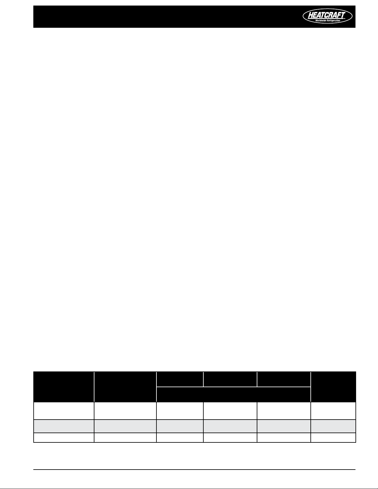
TABLE 1 Model PST | Default Temperature Control Settings
Application:
Temperature set
points
Cooler: 35˚ F
Cooler w/ Electric
Defrost: 34˚ F
Defrost start times
Every 3 hours of
compressor run time
Defrost
Duration
60 – – 38˚ F
40 2 2 65˚ F
Drip Time Fan Delay
Minutes
Defrost
Termination
Set Point
Freezer: -10˚ F 4 times / day 40 2 2 65˚ F
PRO3 Side Mount Packaged Refrigeration System Installation and Operations Manual, May 2008 7
Installation and Operations Manual
Programming XR-40CX or XR-60CX
Dixell Electronic Controller
Reprinted with permission from Dixell.
The Dixell XR-40CX (High Temperature) and XR-60CX (Medium
and Low Temperature) are fully configurable electronic
refrigeration controllers. These controls are used on PRO3 Side
Mount units. All parameter values are reprogrammable and are
stored in the non-volatile memory.
The controller uses two levels of programming that can be
accessed through the keypad. The rst level is the user level. It
gives access to six settings — temperature dierential, defrost
cycle intervals, defrost termination temperature, draining time,
defrost fan delay and fan stop temperature.
The second level is the service level. It allows access to all other
parameters. It is recommended that changes in this level be
made only by a qualied technician.
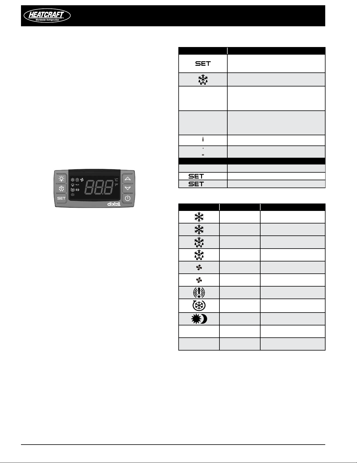
Front Panel Commands
BUTTON COMMAND
To display target set point; in
programming mode it selects a parameter
or conrm an operation
(DEF) To start a manual defrost
(UP): To see the max. stored temperature;
in programming mode it browses
the parameter codes or increases the
displayed value
(DOWN) To see the min stored
temperature; in programming mode it
browses the parameter codes or decreases
the displayed value
To switch the instrument o, if onF = oFF
Not enabled
KEY COMBINATIONS
+
+
+
To lock & unlock the keyboard
To enter in programming mode
To return to the room temperature display
Use of LEDs
LED LED MODE FUNCTION
ON Compressor enabled
Flashing
ON Defrost enabled
Anti-short cycle delay
enabled
Flashing Drip time in progress
ON Fans enabled (XR60CX only)
Flashing
ON An alarm is occurring
ON Continuous cycle is running
ON Energy saving enabled
°C/°F ON Measurement unit
°C/°F Flashing Programming phase
Fans delay after defrost in
progress (XR60CX only)
8
 Loading...