

Installation and
Operations Manual
Bulletin H-IM-PSM May 2008 Part Number 25008001
PRO3 Side Mount
Packaged Refrigeration System

Table of Contents
Inspection............................................................................3
Installation Requirements .................................................3
Recommended Unit Placement
FIGUR E 1: System Space Requirements | Back View
FIGUR E 2: System Space Requirements | Side View
Access Requirements .........................................................3
Condensing Unit Section (Exterior of box)
FIGUR E 3: Access Requirements | Top View
Evaporator Section (Interior of box)
Installation Procedures ..................................................4-7
FIGUR E 4: Cutout Location
FIGUR E 5: Cutout Dimensions | Small Cabinet
FIGUR E 6: Cutout Dimensions | Large Cabinet
FIGUR E7: Plug Detail
FIGUR E 8: Plug Detail | Small Cabinet
FIGUR E9: Plug Detail | Large Cabinet
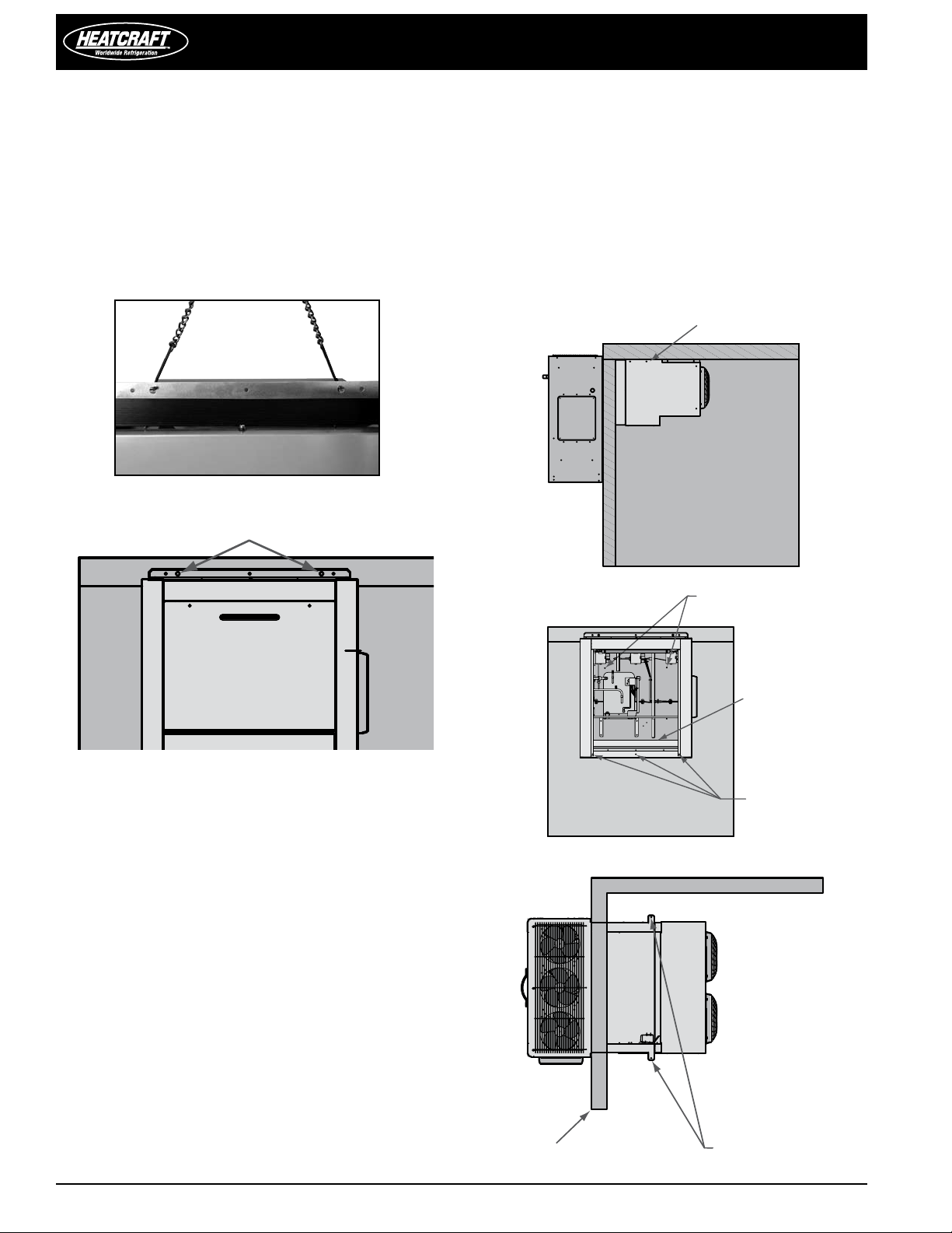
Rigging
FIGUR E10: Rigging Holes
FIGUR E 11: Rigging Holes | Front View
Mounting
FIGUR E12: Mounting Holes | Side View
FIGUR E 13: Mounting Holes | Front View
FIGUR E 14: Mounting Holes | Top View
Electrical Connection
Refrigeration Sequence of Operation ...............................7
TABLE 1 Model PST | Default Temperature Control Settings
Cooler Temperature Control
Coolers: Air-defrost Operation
Cooler with Electric Defrost and Freezer Temperature/
Defrost Control
Cooler with Electric Defrost and Freezer Sequence of
Operation
Programming Electronic Controller ............................ 8-16
Dixell Electronic Controller (XR40CX and XR60CX)
Front Panel Commands ..................................................................8
Use of LEDs...........................................................................................8
Max. & Min. Temperature Memorization: .................................9
How to See the Min. Temperature
How to See the Max. Temperature
How to Reset the Max. & Min. Temperature Recorded
Main Functions: .................................................................................9
How to see the set-point
How to change the set-point
How to start a manual defrost
How to change a parameter value
Installation and Operations Manual
The Hidden Menu .............................................................................9
How to Enter the Hidden Parameters
How to Move a Parameter from the Hidden Menu
How to Lock the Keyboard
The Continuous Cycle
The On/O Function
Parameters .................................................................................10-11
Regulation
Display
Defrost
Fans (XR60CX ONLY)
Alarms
How to use the Hot Key ................................................................11
How to program a Hot Key from the Instrument
Alarm Signals ...................................................................................12
Alarm Recovery
Other Messages ..............................................................................12
Technical Data .................................................................................12
Connections .....................................................................................13
Service Information..........................................................13
Maintenance
System Standard Maintenance Guidelines
Drain Pan Removal..............................................................................14
FIGURE 15: Drain Pan Removal | View A
FIGURE 16: Drain Pan Removal | View B
Wiring Diagrams ......................................................... 15-18
DIAGRAM 1 High Temperature Cooler | Air Defrost | Large Cabinet
DIAGRAM 2
DIAGRAM 3 Freezer and Medium Temperature Cooler | Electric Defrost | Small Cabinet
DIAGRAM
Performance, Capacities and Specications ..................19
TABLE 2 Cooler Application | Air Defrost | BTUH at 95°F ambient
TABLE
TABLE
TABLE
Dimensions ................................................................. 20-21
DIAGRAM 5 Dimensions | Small Cabinet: 1-fan | Top view
DIAGRAM
DIAGRAM
DIAGRAM
DIAGRAM
DIAGRAM
Replacement Parts by InterLink .....................................22
TABLE 6 Replacement Parts List
Warranty Statement ........................................................23
High Temperature Cooler | Air Defrost | Small Cabinet
4 Freezer and Medium Temperature Cooler | Electric Defrost | Large Cabinet
3 Cooler Application | Electric Defrost | BTUH at 95°F ambient
4 Freezer Application | Electric Defrost | BTUH at 95°F ambient
5 Specications
6 Dimensions | Small Cabinet: 1-fan | Side view
7 Dimensions | Small Cabinet: 1-fan | Back view
8 Dimensions | Large Cabinet: 2-fan | Top view
9 Dimensions | Large Cabinet: 1-fan | Side view
10 Dimensions | Large Cabinet: 1-fan | Back view
2
© 2008 Heatcraft Refrigeration Products LLC
PRO3 Side Mount Packaged Refrigeration System
Leave this area unobstructed
Leave these areas
unobstructed
24"
4.00
18"18"
24"
36"
8"
Inspection
1. Each shipment should be carefully checked against the bill
of lading.
2. The shipping receipt should not be signed until all items listed
on the bill of lading have been accounted for.
3. Check packaging for signs of damage.
4. Any shortage or damages should be immediately reported to
the delivering carrier.
5. Damaged material becomes the delivering carrier’s
responsibility, and should not be returned to the manufacturer
unless prior approval is given to do so.
6. All units are shipped on heavy skids and enclosed in open
crating. Generally, it is advisable to bring the unit as close to
its nal location as possible before removing crating.
7. When unpacking the system, care should be taken to
prevent damage.
8. Avoid removing the shipping base until the unit has been
moved to the nal destination.
Installation Requirements
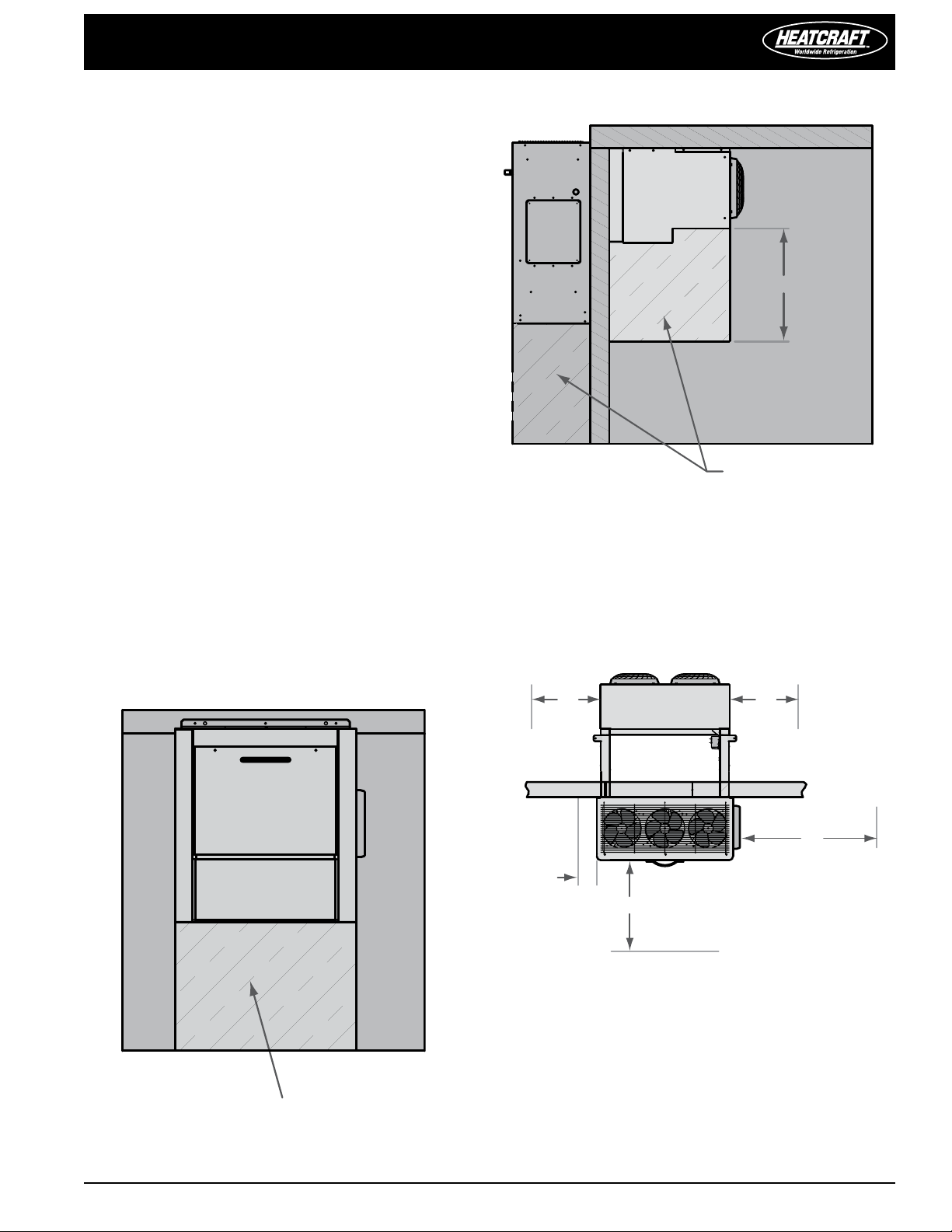
Recommended Unit Placement
1. Ensure that the structural integrity of the box can withstand
the weight of the side-mounted equipment.
2. The air pattern must cover the entire room
3. Location of aisles, racks, etc. must be known
4. For space requirements,
see FIGURES 1 and 2
2: System Space Requirements | Side View
FIGUR E
Access Requirements
Condensing Unit Section (Exterior of box)
Provide adequate access space (minimum 36") on the right side of
the unit for electric box clearance. The front of the unit should have
a minimum of 24" clearance for compressor and fan motor service.
The left side of the unit should be a minimum of 8" clearance.
FIGUR E
3: Access Requirements | Top View
FIGUR E 1: System Space Requirements | Back View
Evaporator Section (Interior of box)
The front of the evaporator should have no obstructions since this
is the leaving airside of the evaporator. There should also be no
obstructions under the evaporator. A minimum of 8" clearance should
be held on each side of the evaporator for drain pan removal.
PRO3 Side Mount Packaged Refrigeration System Installation and Operations Manual, May 2008 3
Installation and Operations Manual
2.62" TYP
20.25" TYP
22.75" TYP
CUTOUTS
2.62" TYP
20.25" TYP
28.75" TYP
CUTOUTS
Installation Procedures
NOTE: Installation and maintenance to be performed only
by qualied personnel who are familiar with local codes and
regulations and are experienced with this type of equipment.
CAUTION: Make sure all power sources are disconnected
before any service work is done on units.
A.) Inspect packaging/unit for shipping damage
B.) Review the space and location requirements provided for your
method of installation.
C.) Follow installation instructions listed in method #1 or #2
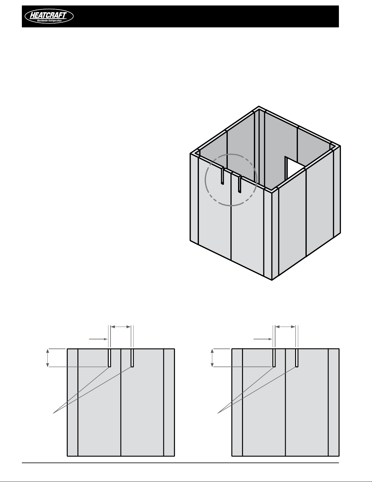
Installation Method #1
Top Installation (See FIGURES 4, 5 and 6)
This installation method is the recommended installation method
in applications where it is feasible.
In order to install a unit using this method, you will need to provide
cutout slots for the “arms.” The unit should be placed on the wall
prior to setting and securing the roof of the box.
Please use the following guidelines when completing the installation
in this manner.
1. You will need to provide nished slots with the appropriate
dimensions in the box wall.
2. The slots can straddle a seam but they should not be on a seam.
See FIGURE 4.
3. The cut-out sections should not be placed in a location where
they would interfere with any cam locks.
4. It is preferred that a cam lock be placed in between the cutouts
to give additional support
See FIGURES 5 and 6.
5. The unit will need to be lifted to the appropriate height and
inserted into the open slots. The bottom of the unit should
be temporarily supported during the remainder of the installation
process (no portion of the unit should be supported by the
bottom of the evaporator section as this WILL cause damage to
the drain pan).
6. Set and secure the roof of the box and rmly attach the unit to
the box and carefully seal all seams and penetration points.
FIGUR E 4: Cutout Location
FIGUR E 5:
Cutout Dimensions | Small Cabinet
CAUTION: Do not support any portion of the unit by the
drain pan.
FIGUR E 6: Cutout Dimensions | Large Cabinet
4
PRO3 Side Mount Packaged Refrigeration System
SEE PLUG DETAIL
29.00
20.07
CAMLOCKS
4 PLACES
20.00
23.00
CAMLOCKS
4 PLACES
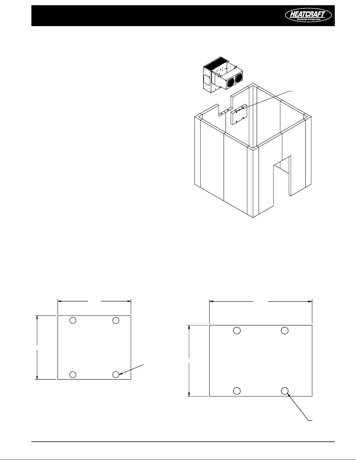
Installation Method #2
Side Installation (See FIGURES 7, 8, and 9)
This installation method is intended for applications that have
height restrictions that do not allow the unit to be installed from
above (see method #1) and installations into pre-existing boxes
where it is impractical to remove the roof.
In order to install a unit using this method, you must provide an
additional “plug” section of the box to ll in the open space between
evaporator arms after installation. This section should contain cam
locks to anchor it in place.
Please use the following guidelines when completing the installation
in this manner.
1. Provide a nished opening with the appropriate dimensions
from FIGURE
2.
The cut-out section should not be placed in a location where it
would degrade the structural integrity of the box (should not
interfere with cam locks)
3. The unit will need to be lifted to the appropriate height and
inserted into the open slot. The bottom of the unit should be
temporarily supported during the remainder of the installation
process (no portion of the unit should be supported by the
bottom of the evaporator section as this WILL cause damage to
the drain pan).
4. You should use cam locks to re-connect the “plug” section after
installing the unit, rmly attach the unit to the box and carefully
seal all seams.
8 or 9.
FIGUR E 7: Plug Detail
FIGUR E 8:
Plug Detail | Small Cabinet
FIGUR E 9:
Plug Detail | Large Cabinet
PRO3 Side Mount Packaged Refrigeration System Installation and Operations Manual, May 2008 5
Installation and Operations Manual
Mounting
holes
Front panels
removed
for clarity
Mounting holes
Mounting holes
Top not shown
for clarity
Mounting holes
Rigging holes
Rigging
CAUTION: Avoid contact with sharp edges and coil
surfaces. They are a potential injury hazard. Wear gloves
during moving and rigging.
Caution should be exercised when moving these units. To prevent
damage to the unit housing during rigging, cables or chains used
must be held apart by spacer bars. Rigging holes are provided on
all models. See FIGURES 10 and 11.
FIGUR E 10: Rigging Holes
FIGUR E 11: Rigging Holes | Front View
4. Ensure that the condensing unit airow is not obstructed after
removing the temporary support.
5. Do not obstruct the evaporator airow with shelving. The area
below the evaporator should be left completely open.
6. Connect unit to power supply through knock-out provided
above electrical box using all local wiring codes.
7. Apply power to unit. All controls are preset to factory default
settings. See Table 1 (next page).
8. Check the unit for proper operation.
FIGUR E 12: Mounting Holes | Side View
Mounting
The system requires two through-bolts to be used to connect to
the roof panel. A minimum of four through-bolts should be used to
connect to the side panel of the box. The opposite side of the box
should be reinforced with wood or metal to prevent the bolts from
pulling through the panel. See FIGURES 12, 13 and 14 for locations.
Through bolts should be insulated or non-conductive to prevent
sweating. All penetrations to the box should be caulked to prevent
moisture from entering the box.
1. Install two through bolts to secure the unit to the wall. The inside
of the box should be reinforced with wood or metal for proper
when mounting of the unit to the box with through bolts.
2. Install and secure the roof of the box. Inside the box,
provisions have been made to secure the evaporator section
to the roof panel with through bolts.
3. The area between the evaporator section and the roof
panel should be caulked to meet NSF codes. In addition, the
openings where the unit was lowered into the box panel
should be caulked to prevent any inltration from the outside
area into the box.
FIGURE 13: Mounting Holes | Front View
FIGURE 14: Mounting Holes | Top View
6
PRO3 Side Mount Packaged Refrigeration System
Electrical Connection
1. Refer to all local codes for proper connection.
2. A knock-out is provided for 1" conduit on the side of the
condensing unit section above the electrical box. See FIGURE 12.
3. Wire will be brought into the electrical box through the
bottom of the electrical box and connected to the top of the
contactor.
Refrigeration Sequence of Operation
1. Power is provided to the temperature control, compressor
contactor and cooler evaporator fans.
2. The temperature controller closes and energizes the
compressor contactor, starting the compressor, evaporator
and condenser fan(s).
3. When the system reaches the desired box temperature, the
temperature control will de-energize the compressor contactor.
Evaporator fans will continue to operate at this point.
4. When the xture temperature rises above the set point
and minimum o-time has elapsed, the temperature control
will close and re-energize the compressor contactor.
Coolers: Air-defrost Operation
Air defrost units are pre-programmed for 4 defrost per day. These
periods are reprogrammable. When the coil temperature reaches
38°F, the control will terminate the defrost cycle.
For programming information see pages 7-16.
Cooler with Electric Defrost and Freezer
Temperature/Defrost Control
PRO3 packaged refrigeration system cooler with electric defrost and
freezer units come factory equipped with an electronic temperature/
defrost control.
For programming information see pages 7-16.
Cooler with Electric Defrost and Freezer
Sequence of Operation
Power is provided to the temperature control and compressor
contactor. The drain line heater as well as the crankcase heaters will
also have continuous power supplied to them.
The temperature controller energizes the compressor contactor,
starting the compressor and condenser fan(s). The evaporator fans
will be energized by the electronic controller.
When the system reaches the desired box temperature, the
temperature control will de-energize the compressor contactor and
the evaporator fans.
When the temperature rises above the set point and minimum otime (4 minutes) has elapsed, the temperature control will close and
re-energize the compressor contactor.
1. During normal operation, at the preset times of day, the
temperature/defrost control will de-energize the compressor
contactor and evaporator fans and energize the defrost
heaters. These functions are controlled through relays on the
controller.
2. When the coil has defrosted fully and has reached the preset
coil temperature (as sensed by the coil temperature sensor)
the defrost heater de-energizes and the fan delay and drip
sequences begin.
3. The temperature/defrost control energizes the compressor
contactor, starting the compressor and condenser fan(s).
4. Freezer evaporator fans will be energized by the temperature/
defrost control when the coil temperature reaches 35°F or fan
delay time has elapsed.
TABLE 1 Model PST | Default Temperature Control Settings
Application:
Temperature set
points
Cooler: 35˚ F
Cooler w/ Electric
Defrost: 34˚ F
Defrost start times
Every 3 hours of
compressor run time
Defrost
Duration
60 – – 38˚ F
40 2 2 65˚ F
Drip Time Fan Delay
Minutes
Defrost
Termination
Set Point
Freezer: -10˚ F 4 times / day 40 2 2 65˚ F
PRO3 Side Mount Packaged Refrigeration System Installation and Operations Manual, May 2008 7
Installation and Operations Manual
Programming XR-40CX or XR-60CX
Dixell Electronic Controller
Reprinted with permission from Dixell.
The Dixell XR-40CX (High Temperature) and XR-60CX (Medium
and Low Temperature) are fully configurable electronic
refrigeration controllers. These controls are used on PRO3 Side
Mount units. All parameter values are reprogrammable and are
stored in the non-volatile memory.
The controller uses two levels of programming that can be
accessed through the keypad. The rst level is the user level. It
gives access to six settings — temperature dierential, defrost
cycle intervals, defrost termination temperature, draining time,
defrost fan delay and fan stop temperature.
The second level is the service level. It allows access to all other
parameters. It is recommended that changes in this level be
made only by a qualied technician.
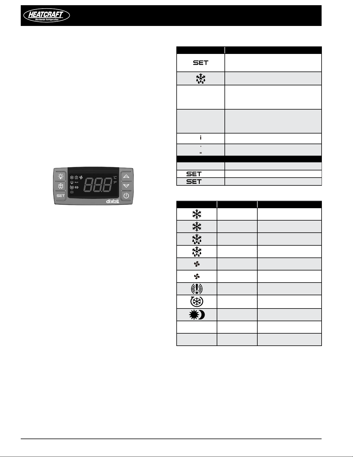
Front Panel Commands
BUTTON COMMAND
To display target set point; in
programming mode it selects a parameter
or conrm an operation
(DEF) To start a manual defrost
(UP): To see the max. stored temperature;
in programming mode it browses
the parameter codes or increases the
displayed value
(DOWN) To see the min stored
temperature; in programming mode it
browses the parameter codes or decreases
the displayed value
To switch the instrument o, if onF = oFF
Not enabled
KEY COMBINATIONS
+
+
+
To lock & unlock the keyboard
To enter in programming mode
To return to the room temperature display
Use of LEDs
LED LED MODE FUNCTION
ON Compressor enabled
Flashing
ON Defrost enabled
Anti-short cycle delay
enabled
Flashing Drip time in progress
ON Fans enabled (XR60CX only)
Flashing
ON An alarm is occurring
ON Continuous cycle is running
ON Energy saving enabled
°C/°F ON Measurement unit
°C/°F Flashing Programming phase
Fans delay after defrost in
progress (XR60CX only)
8

PRO3 Side Mount Packaged Refrigeration System
Max. & Min. Temperature Memorization
HOW TO SEE THE MIN. TEMPERATURE
1. Press and release the DOWN key.
2. The “Lo” message will be displayed followed by the minimum
temperature recorded.
3. By pressing the DOWN key again or by waiting 5 seconds the
normal display will be restored.
HOW TO SEE THE MAX. TEMPERATURE
1. Press and release the UP key.
2. The “Hi” message will be displayed followed by the maximum
temperature recorded.
3. By pressing the UP key again or by waiting 5 seconds the
normal display will be restored.
HOW TO RESET THE MAX AND MIN TEMPERATURE RECORDED
1. Hold press the SET key for more than 3 seconds, while the
max. or min temperature is displayed. (rSt message will
be displayed)
2. To conrm the operation the “rSt” message starts blinking and
the normal temperature will be displayed
Main Functions
HOW TO SEE THE SETPOINT
1. Push and immediately release SET key: the
display will show the set point value
2. Push and immediately release the SET key or wait 5 seconds to
display the probe value again
HOW TO CHANGE THE SETPOINT
1. Push SET for more than 2 seconds to change the set-point value
2. The value of the set-point will be displayed and the °C or °F
LED starts blinking
3. To change the set value push UP or DOWN arrows within 10
seconds
4. To memorize the new set point value push SET key again or
wait 10 seconds
HOW TO START A MANUAL DEFROST
Push DEF key for more than 2 seconds and a manual
defrost will start.
HOW TO CHANGE A PARAMETER VALUE
To change a parameter value:
1.
Enter the Programming mode by pressing the SET + DOWN
keys for 3 seconds (the °C or °F LED starts blinking)
2.
Select the required parameter. Press SET to display its value.
3.
Use UP or DOWN to change its value
4.
Press SET to store the new value and move to the following
parameter
To exit: Press SET + UP or wait 15 seconds without pressing a key
NOTE: The set value is stored even when the procedure is exited by
waiting the time-out to expire.
The Hidden Menu
The hidden menu Includes all the parameters of the instrument.
HOW TO ENTER THE HIDDEN PARAMETERS
1. Enter the Programming mode by pressing the Set + DOWN
keys for 3 seconds (the °C or °F LED starts blinking).
2. Release the keys, then push again the Set+DOWN keys
for more than 7 seconds. The Pr2 label will be displayed
immediately followed from the HY parameter.
NOW YOU ARE IN THE HIDDEN MENU
3. Select the required parameter.
4. Press the SET key to display its value
5. Use UP or DOWN to change its value.
6. Press SET to store the new value and move to the following
parameter.
To exit: Press SET + UP or wait 15 seconds without pressing a key.
NOTE 1: If no parameter is present in Pr1, after 3 seconds the “noP”
message is displayed. Keep the keys pushed until the Pr2 message
is displayed.
NOTE 2: The set value is stored even when the procedure is exited
by waiting the time-out to expire.
HOW TO MOVE A PARAMETER FROM THE HIDDEN MENU TO
THE FIRST LEVEL AND VICE VERSA
Each parameter present in the HIDDEN MENU can be removed or
put into “THE FIRST LEVEL” (user level) by pressing SET + Down.
In HIDDEN MENU when a parameter is present in First Level the
decimal point is on.
HOW TO LOCK THE KEYBOARD
1. Keep the UP + DOWN keys pressed for more than 3 seconds.
2. The “POF” message will be displayed and the keyboard will be
locked. At this point it will be possible only to see the set point
or the MAX o Min temperature stored
3. If a key is pressed more than 3 seconds the “POF” message will
be displayed.
To unlock the keyboard
Keep the UP + DOWN keys pressed for more than 3 seconds, until
the “Pon” message is displayed.
The continuous cycle
When defrost is not in progress, it can be activated by holding the
UP key pressed for about 3 seconds. The compressor operates to
maintain the ccS set point for the time set through the CCt parameter.
The cycle can be terminated before the end of the set time using the
same activation key UP for 3 seconds.
The on/o function
With “onF = oFF”, pushing the ON/OFF key, the instrument is
switched o. The “OFF” message is displayed. In this conguration,
To switch the instrument on, push again the ON/OFF key.
WARNING: Loads connected to the normally closed contacts of
the relays are always supplied and under voltage, even if the
instrument is in stand by mode.
PRO3 Side Mount Packaged Refrigeration System Installation and Operations Manual, May 2008 9

Installation and Operations Manual
Parameters
DEFAULT SETTINGS
Label Characteristic Description
REGULATION
SEt Set Point LS ~ US -10 34 38
(0,1 ÷ 25,5°C / 1÷255 °F) Intervention
dierential for set point. Compressor
Hy Dierential
LS Minimum set point
US Maximum set point
Thermostat probe
Ot
calibration
Outputs activation
OdS
delay at start up
Anti-short cycle
AC
delay
Compressor OFF
COF
time with faulty
probe
DISPLAY
Temperature
CF
measurement unit
DEFROST
tdF Defrost type EL = electrical heater; in = hot gas Pr2
Defrost termination
dtE
temperature
Interval between
IdF
defrost cycles
(Maximum) length
MdF
for defrost
Fdt Drip time
Cut IN is Set Point + dierential (Hy).
Compressor Cut OUT is when the
temperature reaches the set point
(- 50°C÷SET/-58°F÷SET): Sets the
minimum value for the set point..
(SET÷110°C/ SET÷230°F). Set the
maximum value for set point.
(-12.0÷12.0°C; -120÷120°F) allows
to adjust possible oset of the
thermostat probe
(0÷255min) This function is
enabled at the initial start up of the
instrument and inhibits any output
activation for the period of time set in
the parameter
(0÷50 min) minimum interval
between the compressor stop and
the following restart
(0÷255 min) time during which the
compressor is OFF in case of faulty
thermostat probe. With COF=0
compressor is always active
°C=Celsius; °F=Fahrenheit. WARNING:
When the measurement unit is
changed the SET point and the values
of the parameters Hy, LS, US, Ot, ALU
and ALL have to be checked and
modied if necessary
(-50÷50 °C/ -58÷122°F) (Enabled only
when EdF=Pb) sets the temperature
measured by the evaporator probe,
which causes the end of defrost
(0÷120h) Determines the time
interval between the beginning of
two defrost cycles
(0÷255min) When P2P = n, (not
evaporator probe: timed defrost) it
sets the defrost duration, when P2P =
y (defrost end based on temperature)
it sets the maximum length for defrost
(0÷120 min) time interval between
reaching defrost termination
temperature and the restoring of the
control’s normal operation. This time
allows the evaporator to eliminate
water drops that might have formed
due to defrost
Menu/User
Level
Pr1 1~ 45 3 3 3
Pr2
Pr2 SET ~ 302F
Pr2 -21~21
Pr2
Pr2
Pr2
Pr2
Pr1 -58~122 65 65 38
Pr1 0 ~ 120 hours 6 6 6
Pr2
Pr1
Possible
Settings
-67 ~ SET -23 25 33
0 ~ 255
minutes
0 ~ 50 minutes 4 4 4
0 ~ 255
minutes
°C = Celsius
°F =Fahrenheit
EL = electric
defrost / in =
hot gas defrost
0 ~ 255
minutes
0 ~ 255
minutes
Low
Temp.
37 40 45
0 0 0
0 0 0
6 6 6
°F °F °F
EL EL EL
40 40 60
2 2 0
Medium
Temp.
High
Temp.
10

PRO3 Side Mount Packaged Refrigeration System
Label Characteristic Description
FANS XR60CX ONLY
Fnd
Fct
FSt
ALARMS
ALC
ALU
ALL
Fans delay after
defrost
Temperature
dierential
avoiding short
cycles of fans
Fans stop
temperature
Temperature alarms
conguration
MAXIMUM
temperature alarm
Minimum
temperature alarm
(0÷255min) Interval between end of
defrost and evaporator fans start
(0÷59°C; Fct=0 function disabled).
If the dierence of temperature
between the evaporator and the
room probes is more than the value
of the Fct parameter, the fans are
switched on
(-50÷50°C/122°F) setting of
temperature, detected by
evaporator probe, above which fans
are always OFF
(Ab; rE) Ab= absolute temperature:
alarm temperature is given by the
ALL or ALU values. rE = temperature
alarms are referred to the set point.
Temperature alarm is enabled
when the temperature exceeds the
“SET+ALU” or “SET-ALL” values
(SET÷110°C; SET÷230°F) when this
temperature is reached the alarm is
enabled, after the “ALd” delay time
-50.0 ÷ SET°C; -58÷230°F when this
temperature is reached the alarm is
enabled, after the “ALd” delay time
Menu/User
Level
Possible
Settings
DEFAULT SETTINGS
Low
Temp.
Pr1
Pr2
Pr1 -58~122 35 35
Pr2
Pr2 ALL~ 302
Pr2
0 ~ 255
minutes
0~90 10 10
rE = relative to
set point
Ab = absolute
-58~ ALu -25 15 30
2 2
Ab Ab Ab
38 50 50
Medium
Temp.
High
Temp.
Not
Applicable
Not
Applicable
Not
Applicable
How to Use the Hot Key
HOW TO PROGRAM A HOT KEY FROM THE INSTRUMENT
UPLOAD
1. Program one controller with the front keypad.
2. When the controller is
the “uPL” message appears followed a by ashing “End”
1. Push “SET” key and the End will stop ashing.
2. Turn OFF the instrument remove the “Hot Key”, then turn it
ON again.
NOTE: The “Err” message is displayed for failed programming. In
this case push again o key if you want to restart the upload again
or remove the “Hot key” to abort the operation.
HOW TO PROGRAM A HOT KEY FROM THE INSTRUMENT
DOWNLOAD
1. Turn OFF the instrument.
2. Insert a programmed “Hot Key” into the 5 PIN receptacle and
then turn the Controller ON.
3. Automatically the parameter list of the “Hot Key” is
downloaded into the Controller memory, the “doL” message is
blinking followed a by ashing “End”.
4. After 10 seconds the instrument will restart working with the
new parameters.
5. Remove the “Hot Key”.
NOTE: The message “Err” is displayed for failed programming. In
this case turn the unit o and then on if you want to restart the
download again or remove the “Hot key” to abort the operation.
ON, insert the “Hot key” and push UP;
PRO3 Side Mount Packaged Refrigeration System Installation and Operations Manual, May 2008 11

Installation and Operations Manual
Alarm Signals
MESSAGE CAUSE OUTPUTS
P1 Room probe failure
P2
P3 Third probe failure Outputs unchanged
P4
HA
LA
HA2
LA2
dA Door open Compressor and fans restarts
EA External alarm Output unchanged
Evaporator probe
failure
Fourth probe
failure
Maximum
temperature alarm
Minimum
temperature alarm
Condenser high
temperature
Condenser low
temperature
Compressor output according
to parameters “Con” and “COF”
Defrost end is timed
Outputs unchanged
Outputs unchanged
Outputs unchanged
It depends on the Ac2
parameter
It depends on the bLL
parameter
Alarm Recovery
Probe alarms P1, P2, P3 and P4 start some seconds after the fault
in the related probe; they automatically stop some seconds after
the probe restarts normal operation. Check connections before
replacing the probe.
Temperature alarms HA, LA, HA2 and LA2 automatically stop as soon
as the temperature returns to normal values.
Other Messages
MESSAGE MEANING
Pon Keyboard unlocked
PoF Keyboard locked
noP
noA None alarm is recorded
In programming mode: none parameter is present in Pr1
On the display the selected probe is not enabled
Technical Data
CHARACTERISTIC DESCRIPTION
Housing self extinguishing ABS
Case XR40CX/XR60CX frontal 32x74 mm;
depth 60mm
Mounting XR40CX/XR60CX panel mounting in a
71x29mm panel cut-out
Protection IP20
Frontal protection XR40CX/XR60CX IP65
Connections Screw terminal block ≤ 2,5 mm2 wiring
Power supply according to the model: 12Vac/dc,
±10%; 24Vac/dc, ±10%; 230Vac ±10%,
50/60Hz, 110Vac ±10%, 50/60Hz
Power absorption 3VA max
Display 3 digits, red LED, 14,2 mm high;
Inputs Up to 4 NTC or PTC probes
Digital input free voltage contact
Relay outputs compressor: SPST 8(3) A, 250Vac; SPST
16(6)A 250Vac or 20(8)A 250Vac
defrost: SPDT 8(3) A, 250Vac
fan (XR60CX only): SPST 8(3) A, 250Vac
or SPST 5(2) A
Data storing on the non-volatile memory (EEPROM)
Kind of action 1B
Pollution grade 2
Software class A
Rated impulsive voltage 2500V
Overvoltage Category II
Operating temperature 0÷60 °C
Storage temperature -30÷85 °C
Relative humidity 20÷85% (no condensing)
Measuring and
regulation range
Resolution 0,1 °C or 1°C or 1 °F (selectable)
Accuracy (ambient
temp. 25°C)
NTC probe: -40÷110°C (-40÷230°F)
PTC probe: -50÷150°C (-58÷302°F)
±0,7 °C ±1 digit
12

PRO3 Side Mount Packaged Refrigeration System
N.C.
Line
8(3)A250V~
1 2 3 4 5 66
9 10 11 12
5(1)A
Max
20A
Comp
Def
Evap.
Room
7
Hot Key/IV probe
TTL or. X-REP output
Fan
8
20(8)A250V~
N.C.
Line
8(3)A250V~
1 2 3 4 5 6 6
9 10 11 12
8(3)A
Max
16A
Comp
Def Fan
Evap.
Room
7
Hot Key/IV probe/
TTL or X-REP output
N.C.
1 2 3 4 5 6 7
9 1 0 1 1 1 2
Comp
Def
8
Hot Key/IV Probe
TTL or X-REPoutput
8(3)A250V 8(3)A250V
Line
N.C.
1 2 3 4 5 6 7
9 1 0 1 1 1 2
Comp
Def
.
8
Hot Key/IV probe
TTL or X-REP output
8(3)A250V 20(8)A250V
Line
Connections
XR40CX
The X-REP output excludes the TTL output. It’s present in the
following codes: XR40CX- xx2xx, XR40CX –xx3xx; XR40CX –xx6xx;
XR40CX –xx7xx;
The digital input configurable as third probe is present in the
following codes: XR40CX- xx4xx, XR40CX –xx5xx; XR40CX –xx6xx;
XR40CX –xx7xx;
8A compressor
20A compressor
XR60CX
The X-REP output excludes the TTL output. It’s present in the
following codes: XR60CX- xx2xx, XR60CX –xx3xx; XR60CX –xx6xx;
XR60CX –xx7xx;
The digital input configurable as third probe is present in the
following codes: XR60CX- xx4xx, XR60CX –xx5xx; XR60CX –xx6xx;
XR60CX –xx7xx;
8A or 16A comp. relay - 230 VAC
Service Information
All PRO3 packaged refrigeration system units are designed for
maximum durability, reliability and simplicity. The PRO3 packaged
refrigeration system comes to you ready for operation, fully charged
and with all controls preset at the factory. The following information
is provided as an aid in the event that service is required.
Maintenance
The evaporator section of a PRO3 packaged refrigeration system
should be checked at least once for proper defrosting because the
amount and pattern of frosting can vary greatly.
The frost build-up is dependent on the temperature of the room,
the type of product being stored, how often new product is brought
into the room and percentage of time the door to the room is open.
It may be necessary to periodically change the number of defrost
cycles or adjust the duration of defrost.
System Standard Maintenance Guidelines
After rst year of operation and under normal usage, maintenance
should cover the following items at least once every six months:
1. Check and tighten ALL electrical connections.
2. Check all wiring and insulators.
3. Check contactors for proper operation and for worn contact
points.
4. Check all fan motors. Tighten motor mount bolts/ nuts and
tighten fan set screws.
5. Clean the condenser coil surface.
6. Check the operation of the control system. Make certain all
safety controls are operating properly.
7. Check all defrost controls for proper function.
8. Clean the evaporator coil surface.
9. Clean the drain pan and check the drain pan and drain line for
proper drainage.
CAUTION: Unit is critically charged, care must be taken
not to reduce the system refrigerant charge while
taking pressure readings. Technician must compensate
for any refrigerant that might escape the unit into the
gauge tubing.
20A comp. relay - 230 VAC
PRO3 Side Mount Packaged Refrigeration System Installation and Operations Manual, May 2008 13
NOTE: The compressor relay is 8(3)A or 16(6)A according to the model.

Drain Pan Removal
DRAIN PAN BRACKET SCREWS
DRAIN PAN BRACKET SCREW
DRAIN PAN BRACKET
DRAIN PAN
DRAIN PAN TO EVAP
SUPPORT SCREW
HEATER COVER
HEATER COVER SCREWS
HEATER IN DRAIN PAN
HEATERS
DRAIN PAN BRACKETS
DRAIN PAN
DEFROST HEATER
EVAP SIDE PANEL
EVAP SIDE PANEL
BY
DESCRIPTION
DATE
REV
ECN NO.
1. Remove screws from evaporator side panels
2. Remove evaporator side panels
3. Remove screws connecting drain pan to evaporator supports (2)
4. Remove screws attaching the drain pan bracket to evaporator
supports (2)
5. Remove the screws attaching the drain pan bracket to the
coil endplates (4)
6. Lower the drain pan/heater/bracket assembly
7. Remove nuts and retainers attaching heater.
Reverse process to replace drain pan
FIGURE 15: Drain Pan Removal | View A
Installation and Operations Manual
FIGURE 16: Drain Pan Removal | View B
14

PRO3 Side Mount Packaged Refrigeration System
DLT
CCH
BLACK
BLUE
WN
GRAY
DLH
GRAY
WN
WHITE
YELLOW
BLACK
YELLOW
WN
YELLOW
SW
BLUE
ORANGE
GND
3
1
2
HPS
T1 T2 T3
BLUE
YELLOW
PFC
L1
T1
WN
WN
TFC
CC
CC
L1T1
L2T2
BLACK
BLACK
208-230V/1phase/60HZ
SC
COMPRESSOR
R S
C
RC
2 1
5
SR
RT -- ROOM THERMOSTAT
CFM -- CONDENSER FAN MOTOR
CC -- COMPRESSOR CONTACTOR
EFM -- EVAPORATOR FAN MOTOR
LEGEND
HL -- HEATER LIMIT THERMOSTAT
DH -- DEFROST HEATER
GND -- GROUND
RC -- RUN CAPACITOR
SR -- START RELAY
USE COPPER CONDUCTORS ONLY
FACTORY WIRING
FIELD WIRING
SC -- START CAPACITOR
HPS -- HIGH PRESSURE SWITCH
PRIMARY SINGLE PHASE PROTECTION PROVIDEDPRIMARY SINGLE PHASE PROTECTION PROVIDED
CCH -- CRANKCASE HEATER
PFC -- PRESSURE FAN CYCLE SWITCH
DLT -- DRAIN LINE THERMOSTAT
DLH -- DRAIN LINE HEATER
TFC -- TEMPERATURE FAN CYCLE SWITCH
WN -- WIRE NUT
SW -- SWITCH
EFM
EFM
TOP VIEW OF CONDENSING UNIT
CFM 1
LEFT
CENTER
CFM 2
RIGHT
CFM 3
REFRIGERATION CONTROLLER
61
2
4 5
YELLOW
10
7
1211
ROOM TEMP
3
9
EVAP TEMP
BLUE
8
Wiring Diagrams
DIAGRAM 1 Wiring Diagram | High Temperature Cooler | Air Defrost | Large Cabinet
PRO3 Side Mount Packaged Refrigeration System Installation and Operations Manual, May 2008 15

Installation and Operations Manual
DLT
CCH
BLACK
BLUE
WN
GRAY
DLH
GRAY
WN
WHITE
YELLOW
BLACK
YELLOW
WN
YELLOW
SW
BLUE
ORANGE
GND
3
1
2
HPS
T1 T2 T3
BLUE
YELLOW
T1
L1
PFC
WN
CC
CC
L1T1
L2T2
BLACK
BLACK
208-230V/1phase/60HZ
SC
COMPRESSOR
R S
C
RC
2 1
5
SR
RT -- ROOM THERMOSTAT
CFM -- CONDENSER FAN MOTOR
CC -- COMPRESSOR CONTACTOR
EFM -- EVAPORATOR FAN MOTOR
LEGEND
HL -- HEATER LIMIT THERMOSTAT
DH -- DEFROST HEATER
GND -- GROUND
RC -- RUN CAPACITOR
SR -- START RELAY
USE COPPER CONDUCTORS ONLY
FACTORY WIRING
FIELD WIRING
SC -- START CAPACITOR
HPS -- HIGH PRESSURE SWITCH
PRIMARY SINGLE PHASE PROTECTION PROVIDEDPRIMARY SINGLE PHASE PROTECTION PROVIDED
CCH -- CRANKCASE HEATER
PFC -- PRESSURE FAN CYCLE SWITCH
DLT -- DRAIN LINE THERMOSTAT
DLH -- DRAIN LINE HEATER
TFC -- TEMPERATURE FAN CYCLE SWITCH
WN -- WIRE NUT
SW -- SWITCH
EFM
TOP VIEW OF CONDENSING UNIT
CFM 1
LEFT
RIGHT
CFM 2
CONTROLLER
REFRIGERATION
61
2
4 5
YELLOW
10
7
1211
ROOM TEMP
3
9
EVAP TEMP
BLUE
8
DIAGRAM 2 Wiring Diagram | High Temperature Cooler | Air Defrost | Small Cabinet
16

PRO3 Side Mount Packaged Refrigeration System
DLT
CCH
BLACK
BLUE
WN
GRAY
DLH
GRAY
WN
WHITE
YELLOW
BLACK
YELLOW
WN
YELLOW
YELLOW
DH
SW
BLUE
BLUE
YELLOW
HL
ORANGE
RED
BLACK
GND
3
1
2
H1 H2 F1 F2
XN J
4 3
WHITE
HPS
PFC
L1
T1
WN
CC
CC
L1T1
L2T2
BLACK
BLACK
208-230V/1 phase/60HZ
SC
COMPRESSOR
R S
C
RC
2 1
5
SR
RT -- ROOM THERMOSTAT
CFM -- CONDENSER FAN MOTOR
CC -- COMPRESSOR CONTACTOR
EFM -- EVAPORATOR FAN MOTOR
LEGEND
HL -- HEATER LIMIT THERMOSTAT
DH -- DEFROST HEATER
GND -- GROUND
RC -- RUN CAPACITOR
SR -- START RELAY
USE COPPER CONDUCTORS ONLY
FACTORY WIRING
FIELD WIRING
SC -- START CAPACITOR
HPS -- HIGH PRESSURE SWITCH
PRIMARY SINGLE PHASE PROTECTION PROVIDED
CCH -- CRANKCASE HEATER
PFC -- PRESSURE FAN CYCLE SWITCH
DLT -- DRAIN LINE THERMOSTAT
DLH -- DRAIN LINE HEATER
TFC -- TEMPERATURE FAN CYCLE SWITCH
WN -- WIRE NUT
SW -- SWITCH
EFM
TOP VIEW OF CONDENSING UNIT
CFM 1
LEFT
RIGHT
CFM 2
BLUE
REFRIGERATION CONTROLLER
61
2
4 5
YELLOW
BLUE
107 1211
DEFROST TEMP
ROOM TEMP
DIAGRAM 3 Wiring Diagram | Freezer and Medium Temperature Cooler | Electric Defrost | Small Cabinet
PRO3 Side Mount Packaged Refrigeration System Installation and Operations Manual, May 2008 17

Installation and Operations Manual
TFC
PFC
L1
WN
WN
T1
DLT
CCH
BLACK
BLUE
WN
GRAY
DLH
GRAY
WN
WHITE
YELLOW
BLACK
YELLOW
WN
YELLOW
YELLOW
DH
SW
BLUE
BLUE
YELLOW
HL
ORANGE
RED
BLACK
GND
3
1
2
H1 H2 F1 F2
XN J
4 3
WHITE
HPS
CFM 2
CFM 1
CC
CC
L1T1
L2T2
BLACK
BLACK
208-230V/1 PHASE/60HZ
SC
COMPRESSOR
R S
C
RC
2 1
5
SR
RT -- ROOM THERMOSTAT
CFM -- CONDENSER FAN MOTOR
CC -- COMPRESSOR CONTACTOR
EFM -- EVAPORATOR FAN MOTOR
LEGEND
HL -- HEATER LIMIT THERMOSTAT
DH -- DEFROST HEATER
GND -- GROUND
RC -- RUN CAPACITOR
SR -- START RELAY
USE COPPER CONDUCTORS ONLY
FACTORY WIRING
FIELD WIRING
SC -- START CAPACITOR
HPS -- HIGH PRESSURE SWITCH
PRIMARY SINGLE PHASE PROTECTION PROVIDEDPRIMARY SINGLE PHASE PROTECTION PROVIDED
CCH -- CRANKCASE HEATER
PFC -- PRESSURE FAN CYCLE SWITCH
DLT -- DRAIN LINE THERMOSTAT
DLH -- DRAIN LINE HEATER
TFC -- TEMPERATURE FAN CYCLE SWITCH
WN -- WIRE NUT
SW -- SWITCH
EFM
EFM
CFM 3
LEFT
CENTER RIGHT
TOP VIEW OF CONDENSING UNIT
BLUE
REFRIGERATION CONTROLLER
61
2
4 5
YELLOW
BLUE
107 1211
DEFROST TEMP
ROOM TEMP
DIAGRAM 4 Wiring Diagram | Freezer and Medium Temperature Cooler | Electric Defrost | Large Cabinet
18

PRO3 Side Mount Packaged Refrigeration System
Performance, Capacities and Specications
TABLE 2 Model PST | Cooler Application | Air Defrost | BTUH at 95°F Ambient Temperature
Model
PST070H6B* 6,641 6,968 208-230/1/60 15 20 625 A
PST090H6B* 8,643 9,064 208-230/1/60 15 20 625 A
PST131H6B* 12,448 13,107 208-230/1/60 15 20 1,350 B
PST147H6B* 14,081 14,758 208-230/1/60 15 20 1,350 B
TABLE 3 Model PST | Cooler Application | Electric Defrost | BTUH at 95°F ambient temperature
Model 35°F Box Temperature Voltage MCA MOPD
PST066M6B* 6,641 208-230/1/60 15 20 625 A
PST086M6B* 8,643 208-230/1/60 15 20 625 A
PST124M6B* 12,448 208-230/1/60 15 20 1,350 B
PST141M6B* 14,081 208-230/1/60 15 20 1,350 B
TABLE 4 Model PST | Freezer Application | Electric Defrost | BTUH at 95°F ambient temperature
Model
PST034L6B* 4,746 3,444 2,260 208-230/1/60 15.0 20 625 A
PST051L6B* 6,530 5,121 3,720 208-230/1/60 15.0 20 625 A
PST057L6B* 7,541 5,735 3,918 208-230/1/60 15.0 20 1,350 B
PST077L6B* 10,002 7,716 5,689 208-230/1/60 20.7 35 1,350 B
Box Temperature
35°F 38°F
Box Temperature
0°F -10°F -20°F
Voltage MCA MOPD Evaporator CFM
Evaporator
CFM
Voltage MCA MOPD
Evaporator
CFM
Dimensions
Figure
Dimensions
Figure
Dimensions
Figure
TABLE 5 Model PST | Specications
Model Refrigerant
Coolers
PST070H6B* R-404A 36 260 118
PST090H6B* R-404A 36 265 120
PST131H6B* R-404A 40 320 145
PST147H6B* R-404A 40 325 148
Coolers with electric defrost
PST066M6B* R-404A 36 260 118
PST086M6B* R-404A 36 265 120
PST124M6B* R-404A 40 320 145
PST141M6B* R-404A 40 325 148
Freezers
PST034L6B* R-404A 36 260 118
PST051L6B* R-404A 36 265 120
PST057L6B* R-404A 40 320 145
PST077L6B* R-404A 40 325 148
* H for PSC, E for EC motor on evaporator section only.
WARNING: This equipment may contain a substance that harms public health and the environment by destroying ozone
in the upper atmosphere. Venting of certain refrigerants to the atmosphere may be illegal in your location. Refrigerant
recovery devices should be used when installing or servicing this product. Consult your local codes for requirements in
your location.
WARNING: Refrigerant can be harmful if it is inhaled. Refrigerant must be used and recovered responsibly. Failure to
follow this warning may result in personal injury or death.
Refrigerant
Charge (oz.)
Approximate Net Weight
lbs. kg
PRO3 Side Mount Packaged Refrigeration System Installation and Operations Manual, May 2008 19

Dimensions
49-1/8"
1248 mm
23"
584 mm
28"
711 mm
13-3/8"
340 mm
16-1/4"
413 mm
1-3/4"
30"
31-3/4"
44 mm
762 mm
806 mm
30-1/2"
775 mm
27-7/8"
708 mm
49-1/8"
12-1/4"
29-5/8"
16-5/8"
20-1/4"
1-3/4"
46-1/4"
514 mm
311 mm
422 mm
44 mm
1248 mm
1175 mm
752 mm
32-5/8"
905 mm
17-1/4"
438 mm
30"
762 mm
34"
864 mm
35-5/8"
905 mm
1-3/4"
44 mm
1-5/8"
41 mm
DIAGRAM 5 Dimensions | Small Cabinet: 1-fan | Top View
Installation and Operations Manual
DIAGRAM 6 Dimensions | Small Cabinet: 1-fan | Side View
DIAGRAM 7 Dimensions | Small Cabinet: 1-fan | Back View
20

PRO3 Side Mount Packaged Refrigeration System
49-1/8"
12-1/4"
29-5/8"
16-5/8"
20-1/4"
1-3/4"
46-1/4"
514 mm
311 mm
422 mm
44 mm
1248 mm
1175 mm
752 mm
32-5/8"
905 mm
17-1/4"
438 mm
37-3/4"
36"
36-1/2"
927 mm
34"
864 mm
959 mm
914 mm
49-1/8"
1248 mm
16-1/4"
413 mm
13-3/8"
340 mm
29"
737 mm
1-3/4"
45 mm
33-7/8"
860 mm
36"
914 mm
978 mm
1-5/8"
38-1/2"
1019 mm
40-1/8"
41 mm
1-3/4"
44 mm
DIAGRAM 8 Dimensions | Large Cabinet: 2-fan | Top View
DIAGRAM 9 Dimensions | Large Cabinet: 1-fan | Side View DIAGRAM 10 Dimensions | Large Cabinet: 1-fan | Back View
PRO3 Side Mount Packaged Refrigeration System Installation and Operations Manual, May 2008 21

Installation and Operations Manual
Commercial Refrigeration Parts
Commercial Refrigeration Parts
Replacement Parts by
When contacting the factory for service or replacement parts, refer to the model number and serial number of the unit as stamped on the
serial plate attached to the unit. If replacement parts are required, mention the date of installation of unit and date of failure, along with an
explanation of the malfunctions and a description of the replacement parts required.
TABLE 6 Model PST | Replacement Parts List
Coolers
Coolers with
electric defrost
Freezers
Part Description Part Number
PST034L6B*
PST070H6B*
PST090H6B*
PST131H6B*
PST147H6B*
PST066M6B*
PST086M6B*
PST124M6B*
PST141M6B*
PST051L6B*
Fan Blades
Evaporator 5140C 1 1 2 2 1 1 2 2 1 1 2 2
Condenser 22901901 2 2 3 3 2 2 3 3 2 2 3 3
Fan Motors
Evaporator, PSC - 208/230 volt 25308601 1 1 2 2 1 1 2 2 1 1 2 2
Evaporator, EC - 208/230 volt 25317701 1 1 2 2 1 1 2 2 1 1 2 2
Condenser - 208/230 25308301 2 2 3 3 2 2 3 3 2 2 3 3
Evaporator fan motor bracket 23103301 1 1 2 2 1 1 2 2 1 1 2 2
Condenser fan motor bracket 4000104 2 2 3 3 2 2 3 3 2 2 3 3
Contactors
20A, 230-volt 34915200 1 1 1 1 1 1 1 1 1 1 1
Temperature Control
Freezer control kit -208/230 volt 21300701 1 1 1 1 1 1 1 1 1 1 1 1
Cooler with electric defrost-208/230 volt 21300801 1 1 1 1 1 1 1 1 1 1 1 1
Cooler control kit - 208/240 volt 21300901 1 1 1 1 1 1 1 1 1 1 1 1
Heater limit thermostat 5708L 1 1 1 1 1 1 1 1
Defrost Heaters
Defrost heaters - 230 volt 4312F 3 3 3 3
Defrost heaters - 230 volt 4342L
3 3 3 3
Outdoor Parts
Fan pressure control 28917301 1 1 1 1 1 1 1 1 1 1 1 1
Fan temperature control 5521R 1 1 1 1 1 1 1 1 1 1 1 1
Drain line heater 24753401 1 1 1 1 1 1 1 1 1 1 1 1
Drain line heater thermostat 28917401 1 1 1 1 1 1 1 1 1 1 1 1
* H for PSC, E for EC motor on evaporator section only.
PST057L6B*
PST077L6B*
Right source. Right parts. Right now.
InterLink™ is your link to a complete line of dependable and certied commercial refrigeration
parts, accessories and innovative electronic controls for all Heatcraft Refrigeration Products (HRP)
equipment. At InterLink, we provide our wholesalers with a comprehensive selection of product
solutions and innovative technologies for the installed customer base. And every product is built
to ensure the same high performance standards with which all HRP brands are built — backed by
a dedicated team to serve every customer need, delivering at the best lead times in the industry.
Dependable. Versatile. Courteous.
Finally, one simple source for all your replacement needs from a name you can trust.
22
For parts, please contact:
www.interlinkparts.com or
(800) 686-7278

PRO3 Side Mount Packaged Refrigeration System
Warranty Statement
Heatcraft Refrigeration Products LLC warrants to its direct purchasers
that the PRO3 product, except Service Parts, manufactured by Heatcraft
Refrigeration Products LLC shall be of a merchantable quality, free of
defects in material or workmanship, under normal use and service for
a period of two (2) years from date of original installation, or thirty (30)
months from date of shipment by Heatcraft Refrigeration Products
LLC, whichever rst occurs. Service Parts, for product out of original
warranty, should be so warranted for a period of twelve (12) months
from date of shipment. Any product covered by this order found to
Heatcraft Refrigeration Products LLC’s satisfaction to be defective
upon examination at Heatcraft Refrigeration Products LLC’s factory
will, at Heatcraft Refrigeration Products LLC’s option, be repaired
or replaced and returned to Buyer via lowest common carrier, or
Heatcraft Refrigeration Products LLC may at its option grant Buyer
a credit for the purchase price of the defective article. Upon return
of a defective product to Heatcraft Refrigeration Products LLC’s
plant, freight prepaid, by Buyer, correction of such defect by repair
or replacement, and return freight via lowest common carrier, shall
constitute full performance by Heatcraft Refrigeration Products LLC
of its obligations hereunder.
Hermetic compressors furnished by Heatcraft Refrigeration Products
LLC are subject to the standard warranty terms set forth above, except
that motor compressor replacements or exchanges shall be made
through the nearest authorized wholesaler of the motor compressor
manufacturer (not at Heatcraft Refrigeration Products LLC’s factory)
and no freight shall be allowed for transportation of the motor
compressor to and from the wholesaler. The replacement motor
compressor shall be identical to the model of the motor compressor
being replaced. Additional charges which may be incurred throughout
the substitution of other than identical replacements are not covered
by this warranty.
The foregoing is in lieu of all other warranties, express or implied,
notwithstanding the provisions of the uniform commercial code, the
Magnuson-Moss Warranty-Federal Trade Commission Improvement
Act, or any other statutory or common law, federal or state.
Heatcraft Refrigeration Products LLC makes no warranty expressed or
implied, of tness for any particular purpose, or of any other nature
whatsoever, with respect to products manufactured or sold by
Heatcraft Refrigeration Products LLC hereunder, except as specically
set forth above and on the face hereof. It is expressly understood and
agreed that Heatcraft Refrigeration Products LLC shall not be liable to
buyer, or any customer of Buyer, for direct or indirect, special, incidental,
consequential or penal damages, or for any expenses incurred by
reason of the use or misuse by Buyer or third parties of said products.
To the extent said products may be considered “Consumer Products,”
as dened in Section 101 of the Magnuson-Moss warranty-Federal
Trade Commission Improvement Act, Heatcraft Refrigeration Products
LLC makes no warranty of any kind, express or implied, to “Consumers,”
except as specically set forth above and on the face hereof.
This equipment is designed to operate properly and produce the
rated capacity when installed in accordance with good refrigeration
industry practices.
The following conditions should be adhered to when installing this
unit to maintain the manufacturers warranty:
(a) The power supply to the unit must meet the following
conditions:
A. Three phase voltages must be +/- 10% of nameplate
ratings. Single phase must be within +10% or -5%
of nameplate ratings.
B. Phase imbalance cannot exceed 2%.
(b) All control and safety switch circuits must be properly
connected according to the wiring diagram.
(c) The factory installed wiring must not be changed without
written factory approval.
Optional Three-Year Extended Compressor Warranty
The Equipment Dealer may purchase for the Owner at the time of the
original invoice of the equipment a Three-Year Limited Replacement
Compressor Warranty. This entitles the owner to be reimbursed for
the cost of a replacement compressor, during the third through fth
year of the life of the compressor.
The warranty program functions similarly to the standard warranty
oered. When a compressor failure occurs and the unit is exchanged
“over the counter” at the authorized wholesaler outlet a salvage credit
is issued along with the invoice for the new compressor. Return copies
of both the credit and invoice to the Equipment Dealer along with
the model and serial number of the condensing unit. The Equipment
Dealer will process this claim with the Manufacturer and subsequently
reimburse the Owner for the cost of the new compressor.
This warranty covers the actual compressor only and does not extend
to any labor, trip charges, crane rental, taxes or additional parts,
refrigerant or processing/handling charges required to make the
unit operational.
PRO3 Side Mount Packaged Refrigeration System Installation and Operations Manual, May 2008 23

Heatcraft Refrigeration Products LLC
®
CLIMATE
CONTROL
Commercial Refrigeration Parts
2175 West Park Place Blvd., Stone Mountain, GA 30087
P: (800) 321-1881 • F: (770) 465-5990 • www.heatcraftrpd.com
Since product improvement is a continuing eort, we reserve the right to make changes in specications without notice.
The name behind the brands you trust.
H-IM-PSM-0508 | Version 000
 Loading...