

Masterlog4
User Handbook
Masterlog 4 “Version 2”
(from the 11st march 2008)

Code +050004036 Rel. 1.0 – 11/03/2008
3
OPERATING INSTRUCTIONS
MASTERLOG 4 “Version 2”
The default parameter settings for the MASTERLOG 4 (bn1) are selected for operation with chilling evaporators
equipped with an air defrost system. For a different operating mode one of the following programs may be
selected:
‘bn1’= chilling with air defrost
‘bn2’= chilling with electrical defrost
‘bn3’= refrigeration with electrical defrost
‘bn4’= ambient chilling with air defrost
‘bn5’=‘bn2’ with 2 evaporators
‘bn6’=‘bn3’ with 2 evaporators
”DO NOT USE ‘bn0’”
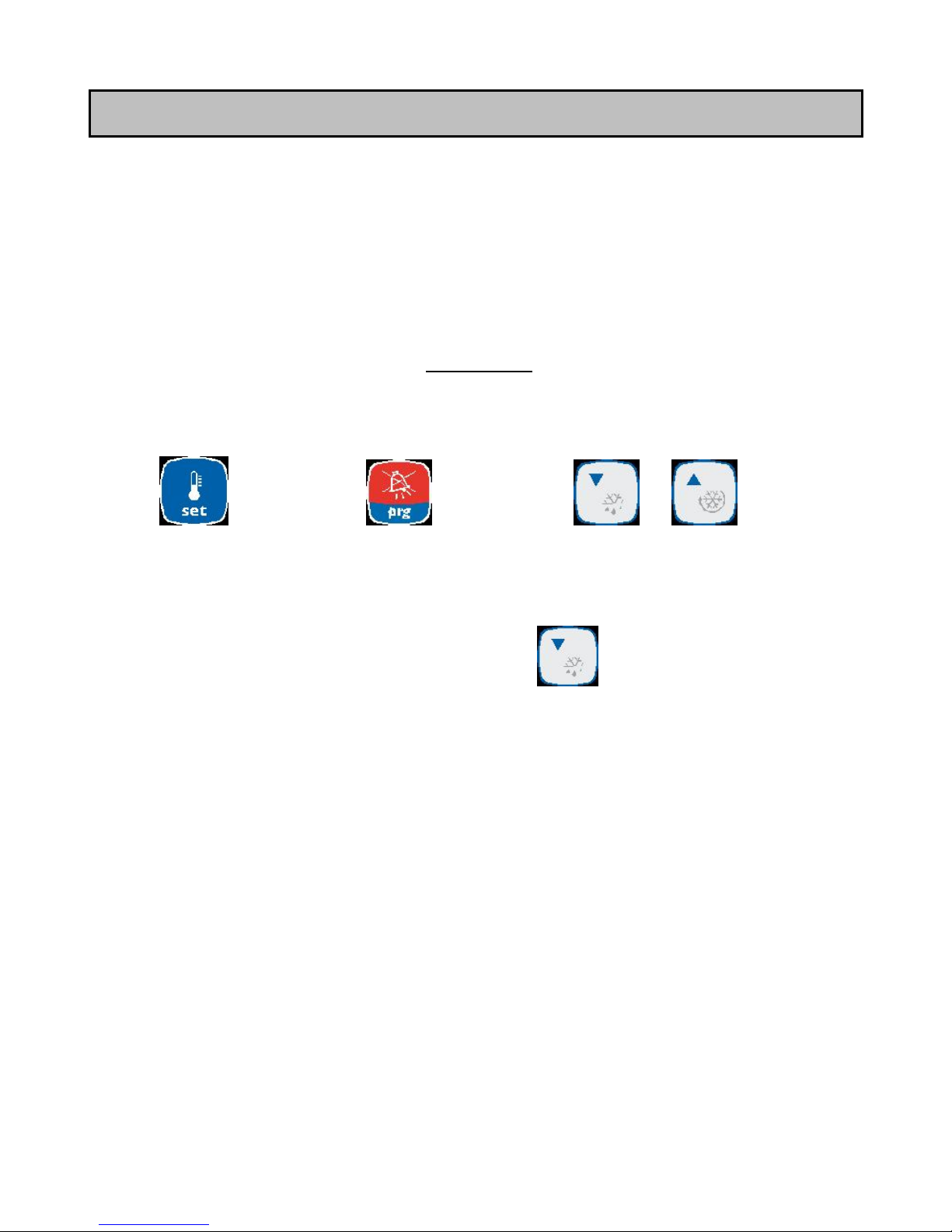
Proceed as follows to select one of these programs:
1. Switch off the Masterlog4.
2. Switch the Masterlog4 back on again while simultaneously
pressing the “prg” button until the value ‘bn0’
appears.
3. Select the program required using the “up” and “down” keys
4. Press “set” to confirm the selection.
”Set” Key ”prg” Key “Up/Down” Keys
ATTENTION:
¾ The defrost parameters [‘dI’: interval between 2 defrosts, ‘dT’: temperature at end of defrost (electrical) and ‘dP’:
maximum defrost duration] are factory-set values. Depending on use of the cold storage room, these parameters
must be modified to ensure correct defrosting of the evaporator.
¾ To carry out a manual defrost cycle, press the “defrost” key
for more than 5 sec.
¾ The MASTERLOG 4 relays are “potential-free” contacts. To supply these contacts, it is essential to connect
terminals 1, 4, 7 and 10 as well as aux. terminals 13 and 16 if necessary (refer to the electrical wiring diagram
enclosed with the products).
¾ The MASTERLOG 4 possesses three configurable inputs (terminals 22/23, 24/25 et 26/27). Input n°1
(terminals 22 and 23) may be set as an external alarm coming from the unit (parameter A4=1, except
application 2 evaporators). Some units are equipped with a standard ‘fault contact’ (refer to wiring diagram).
We recommend you connect this alarm contact to the MASTERLOG 4.
¾ If the keypad is locked, modify the parameter H2 (H2=1).
IMPORTANT: Standard and modified parameters are saved in case of an electrical power failure. When
downloading a program, these values are reset in compliance with the basic parameter setting chart.
Code +050004036 Rel. 1.0 – 11/03/2008
4
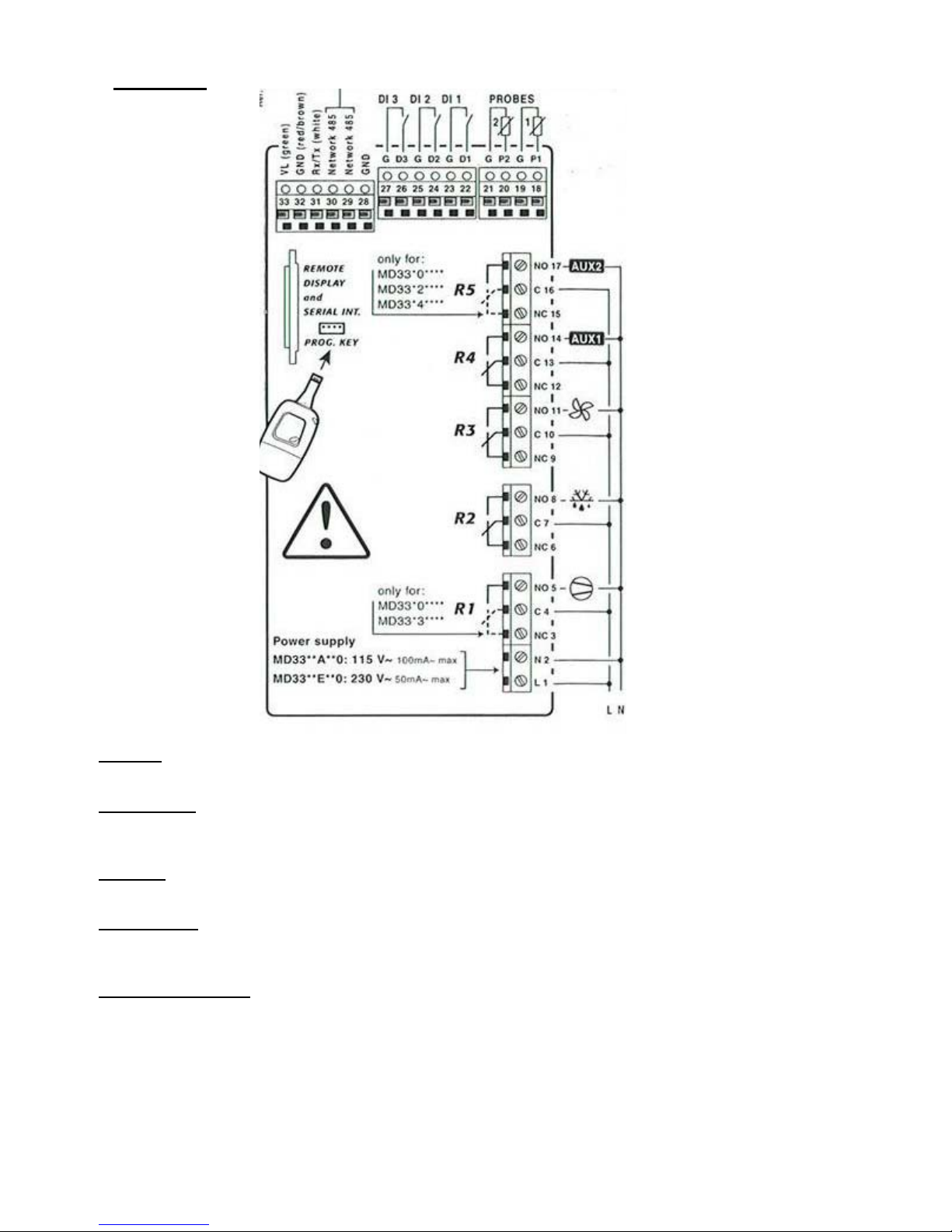
1 - Wiring
Sensors:
18 - 19 Ambient pro be (PROBE 1)
20 - 21 End of defrost probe (PROBE 2)
Digital inputs:
22 - 23 Digital input 1 (DI 1) - Parameters A4
24 - 25 Digital input 2 (DI 2) - Parameters A5
26 - 27 Digital input 3 (DI 3) - Parameters A9
Auxiliary:
13 - 14 AUX 1 – Parameters H1
16 - 17 AUX 2 – Parameters H5
Wiring RS485:
28 GND
29 TX/RX+
30 TX/RX-
Relay characteristics:
Refer to chapter 8. Technical characteristics
R1 =30A
R2=16A
R3=8A
R4=8A
R5=16A
Code +050004036 Rel. 1.0 – 11/03/2008
5
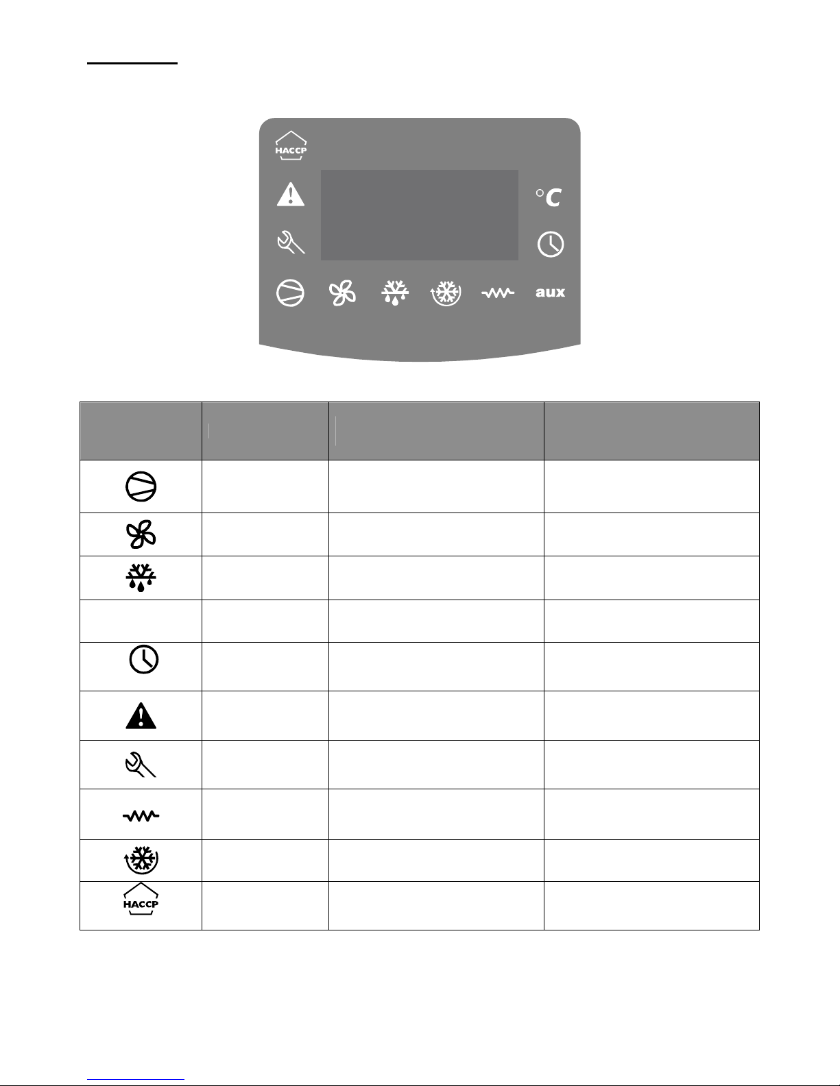
2 - Display
Symbols Colour
Meaning with the symbol
illuminated
Meaning with the symbol
blinking
Amber
Compressor operational
Compressor in standby and ready
to start
Amber
Condenser fan operational
Condenser fan in standby and
ready to start
Amber
Defrost in progress
Condenser fan in standby and
ready to start
AUX
Amber Auxiliary output set as AUX output
Heating element blocking function
enabled at start up
(Option)
Yellow
At least 1 defrost is programmed in
real time
Red External alarm delayed
Alarm present or alarm on digital
input immediate or delayed
Red
Malfunction (e.g. probe
disconnected)
Amber Auxiliary output set as heater
Heating element blocking function
enabled at start up
Amber Activation of a continuous cycle
Continuous cycle cannot be
enabled
(Option)
Red HACCP function enabled New HACCP alarm memorised
Code +050004036 Rel. 1.0 – 11/03/2008
6
3 - Parameters:
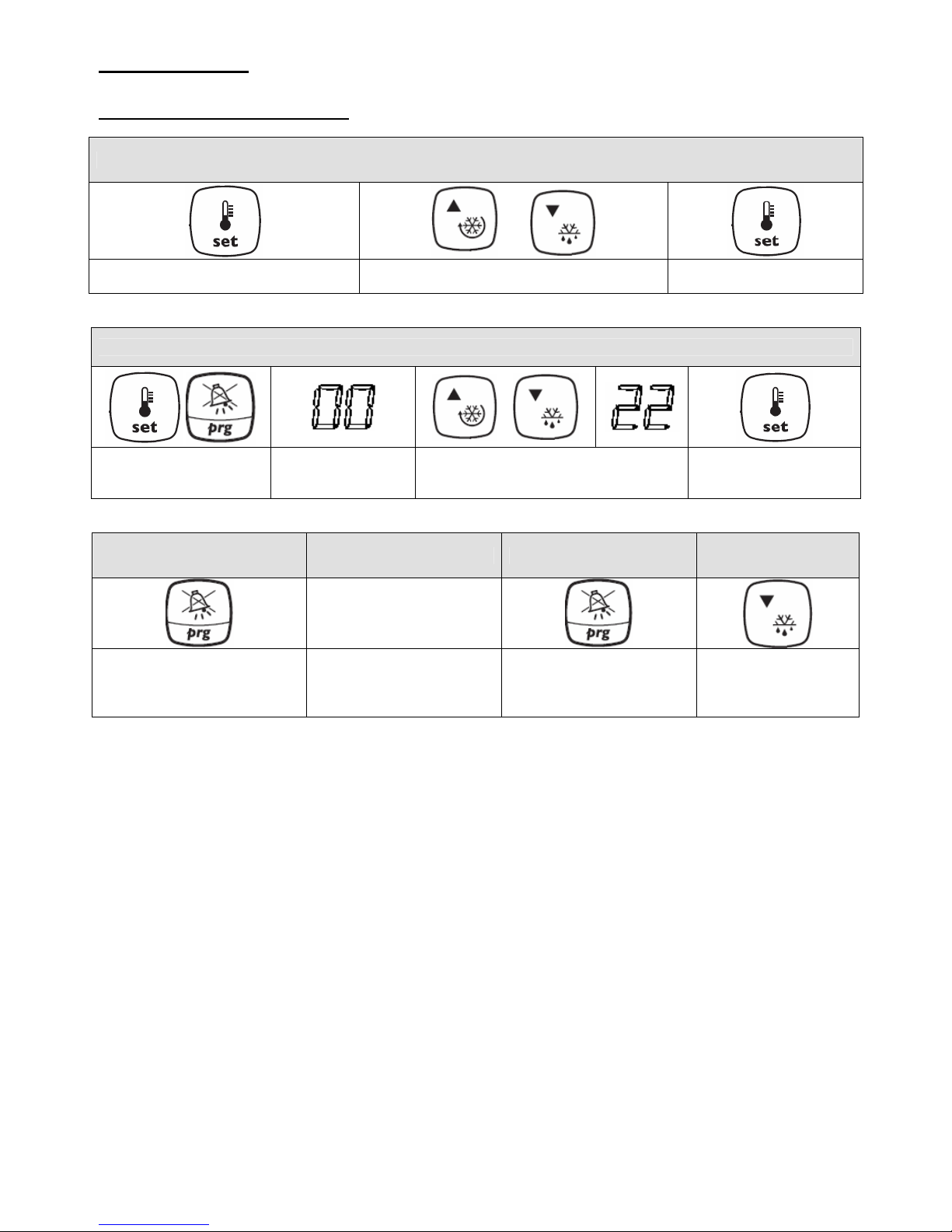
3-1 . Access to parameters:
Modify the set point only
Press and hold SET for 1 second
Use the up and down keys to modify the set
point
Press SET to confirm the
value
Access to all parameters
Press and hold PRG and
SET at the same time for
5 seconds
"00" is displayed
Use the up and down keys to select
“22”
Press SET
Save parameters Do not save parameters Cancel an alarm Manual defrost
Press and hold PRG for 5
seconds
Do not press any other
keys for 60 seconds until
the display returns to the
temperature value
Press PRG
Press and hold DEF
for 5 seconds
Code +050004036 Rel. 1.0 – 11/03/2008
7
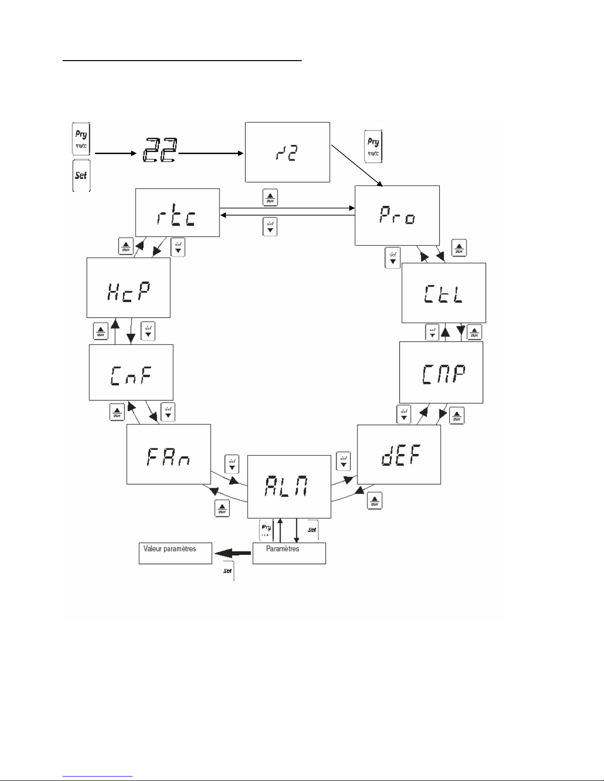
3-2 . Rotation of the parameters list menu
‘Set’= to access or quit a parameter
‘Set’= to access a block
‘Prg’= to quit a block
5s
Probe
Control
Compressor
Defrost
Alarm
Fan
Configuration
HACCP
(OPTION)
(OPTION)
Time range
Code +050004036 Rel. 1.0 – 11/03/2008
8
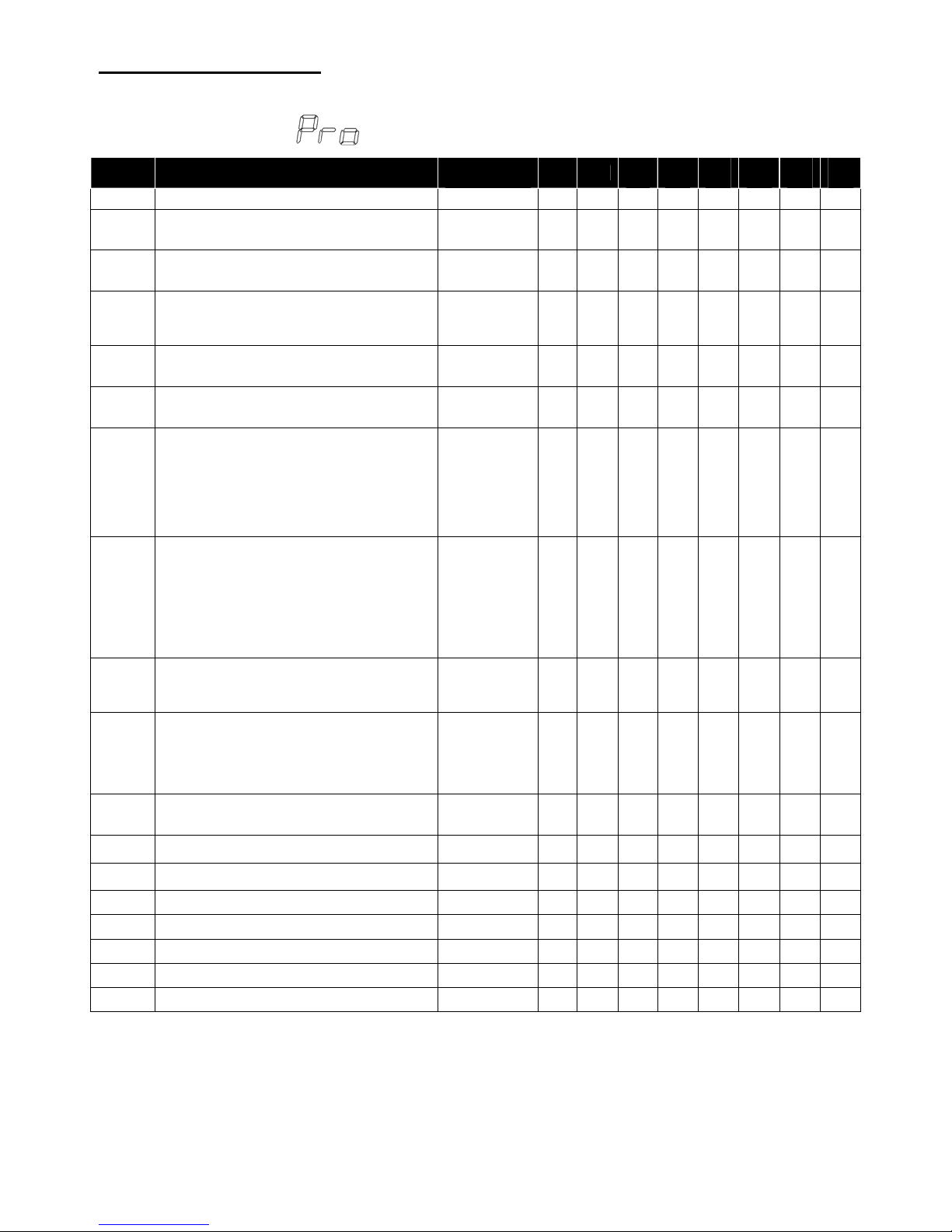
4- List of parameters:
The parameters may vary depending on the model of MD33
/: Probe parameters
Display
Parameter and description
Measurement
unit
Min Max
Bn 1 Bn 2 Bn 3 Bn 4 Bn 5 Bn
6
/2
Probe measurement delay
1=immediate response
15=delayed response
- 1 15 4 4 4 4 4 4
/3
Probe display speed
0=slow
15=fast
- 0 15 0 0 0 0 0 0
/4
Virtual probe (between probe 1 and probe 2)
0=Setting of probe 1
50=average between probe 1 and probe 2
100=Setting of probe 2
- 0 100 0 0 0 0 0 0
/5
Selection °C or °F
0=°C
1=°F
Select 0 1 0 0 0 0 0 0
/6
Display decimal point
0=Yes
1=No
Select 0 1 0 0 0 0 0 0
/tI
Selection of probe to be displayed on controller
1=virtual probe
2=probe 1
3=probe 2
4=probe 3
5=probe 4
6=probe 5
7=set point
- 1 7 2 2 2 2 2 2
tE
Selection of probe to be displayed on a remote
display
0=no remote display present
1=virtual probe
2=probe 1
3=probe 2
4=probe 3
5=probe 4
6=probe 5
- 0 6 0 0 0 0 0 0
/P
Selection of probe type
0=standard NTC (black probe)
1=high-temperature NTC (beige probe)
2=PTC
- 0 2 0 0 0 0 0 0
/A2
Configuration of probe 2
0=probe 2 absent or not used
1=product probe (used for display)
2=defrost probe
3=condensation probe
4=anti-frost probe
- 0 4 0 2 2 0 2 2
/A3
Configuration of probe 3 / digital input 1
Same as probe 2
- 0 4 0 0 0 0 2 2
/A4
Configuration of probe 4 / digital input 2
Same as probe 2
- 0 4 0 0 0 0 0 0
/A5
Configuration of probe 5 / digital input 3
Same as probe 2
- 0 4 0 0 0 0 0 0
/c1
Calibration of probe 1 °C/°F -20 20 0 0 0 0 0 0
/c2
Calibration of probe 2 °C/°F -20 20 0 0 0 0 0 0
/c3
Calibration of probe 3 °C/°F -20 20 0 0 0 0 0 0
/c4
Calibration of probe 4 °C/°F -20 20 0 0 0 0 0 0
/c5
Calibration of probe 5 °C/°F -20 20 0 0 0 0 0 0

Code +050004036 Rel. 1.0 – 11/03/2008
9
r: Setting parameters
Display
Parameter and description
Measurement
unit
Min Max
Bn 1 Bn 2 Bn 3 Bn 4 Bn 5 Bn
6
St
Temperature set point °C/°F r1 r2 4 0 -18 12 0 -18
rd
Differential °C/°F 0.1 20 2 2 2 1 2 2
rn
Dead zone °C/°F 0.0 60 2 2 2 1 2 2
rr
Hot differential relay (with dead zone) °C/°F 0.1 20 2 2 2 1 2 2
r1
Minimum set point value entered by user °C/°F -50 r2 1 -5 -25 2 -5 -25
r2
Maximum set point value entered by user °C/°F r1 200 20 8 -5 20 8 -5
r3
Operating mode
0=direct thermostat (cold) with defrost
1=direct thermostat (cold) without defrost
2=reverse thermostat (hot)
Select 0 2 0 0 0 0 0 0
r4
Variation of set point during nocturnal operation
(stn=st+r4)
°C/°F
-20 20
3 3 3 3 3 3
r5
Authorise recording of min. and max.
temperature values
0=not authorised
1=authorised
Select 0 1 0 0 0 0 0 0
rt
Interval between temperature recordings Time 0 999 - - - - - -
rH
Maximum temperature recorded °C/°F - - - - - - - -
rL
Minimum temperature recorded °C/°F - - - - - - - -
c: Compressor parameters
Display
Parameter and description
Measurement
unit
Min Max
Bn 1 Bn 2 Bn 3 Bn 4 Bn 5 Bn
6
c0
Delay compressor and fan start up when the
controller is switched on
Min 0 15 1 1 1 1 1 1
c1
Minimum time between 2 consecutive start ups
of the same compressor
Min 0 15 6 6 6 6 6 6
c2
Minimum compressor stoppage time Min 0 15 0 0 0 0 0 0
c3
Minimum compressor running time Min 0 15 2 2 2 2 2 2
c4
Compressor running duration in case of probe
alarm (continuous cycle)
Min 0 100 15 15 15 15 15 15
cc
Continuous cycle duration Time 0 15 4 4 4 4 4 4
c6
Temperature alarm exclusion time after a
continuous cycle
Time 0 15 2 2 2 2 2 2
c7
Maximum Pump-Down time (vacuum
generation)
Sec 0 900 0 0 0 0 0 0
c8
Compressor delayed start up after opening the
Pump-Down valve
Sec 0 60 0 0 0 0 0 0
c9
Authorisation of auto-start function during
Pump-Down
0= when the valve is closed
1= each time the valve is closed + LP pressure
switch request when no cooling request is present
Select 0 1 0 0 0 0 0 0
c10
Pump-Down operation in time or in pressure
0=Pump-down in pressure with maximum time
1=Pump-down in time
Select 0 1 0 0 0 0 0 0
c11
Active list of parameters (n° of ‘bn’ ) Sec 0 250 1 2 3 4 5 6

Code +050004036 Rel. 1.0 – 11/03/2008
10
d: Defrost parameters
Display
Parameter and description
Measurement
unit
Min Max
Bn 1 Bn 2 Bn 3 Bn 4 Bn 5 Bn
6
d0
Type of defrost
0=defrost with elec. element ends with
temperature or time
1=defrost with hot gas ends with temperature or
time
2=defrost with elec. element ends with time
3=defrost with hot gas ends with time
4= defrost with elec. element ends with time or
temperature (if defrost ends with time ED1 and ED2
are not displayed)
Select 0 4 2 0 0 2 0 0
dI
Interval between 2 defrosts Time 0 250 8 8 6 12 8 6
dt1
Temperature at end of evaporator defrost °C/°F -50 200 4 4 4 4 4 4
dt2
Temperature at end of aux. evaporator defrost °C/°F -50 200 4 4 4 4 4 4
dP1
Maximum evaporator defrost duration Min 1 250 45 45 30 45 45 30
dP2
Maximum aux. evaporator defrost duration Min 1 250 45 45 30 45 45 30
d3
Delayed defrost activation Min 0 250 0 0 0 0 0 0
d4
Defrost when the controller is switched on
0=no
1=yes
Select 0 1 0 0 0 0 0 0
d5
Delay defrost when the controller is switched on Min 0 250 120 240 240 120 240 240
d6
Block display during defrost
0=alternating display of temperature and DEF
1=display temperature present before defrost
2=always display DEF
- 0 2 2 2 2 2 2 2
dd
Dripping duration after defrost Min 0 15 0 4 4 0 4 4
d8
High-temperature alarm (AH) exclusion duration
after defrost and/or door open
Time 0 15 1 1 1 1 1 1
d8d
Alarm timer after door opening (alarm “dor”) Min 0 250 2 2 2 2 2 2
d9
Priority defrost for delayed compressor
start/stop
0=respected
1=not respected (priority defrost)
Select 0 1 0 0 0 0 0 0
d/1
Read defrost probe 1 °C/°F - - - - - - - -
d/2
Read defrost probe 2 °C/°F - - - - - - - -
dC
Defrost duration time base
0=hours/minutes
1=Minutes/seconds
Select 0 1 0 0 0 0 0 0
d10
Smart defrost: Compressor running time with an
evaporator temperature below D11 to start
defrost
0=function disabled
>0 =running time
dC 0 250 0 0 0 0 0 0
d11
Temperature threshold for smart defrost °C/°F -20 20 1 1 1 1 1 1
d12
Auto-adaptive advanced defrost
0=skip defrost disconnected, automatic variation
disconnected
1=skip defrost disconnected, automatic variation
connected
2= skip defrost connected, automatic variation
disconnected
3= skip defrost connected, automatic variation
connected
- 0 3 0 0 0 0 0 0
dn
Average defrost duration in percentage in
relation to dt1 or dt2
- 1 100 65 65 65 65 65 65
dH
Proportional variation factor of dI - 0 100 50 50 50 50 50 50

Code +050004036 Rel. 1.0 – 11/03/2008
11
A: Alarm parameters
Display
Parameter and description
Measurement
unit
Min Max
Bn 1 Bn 2 Bn 3 Bn 4 Bn 5 Bn
6
A0
Alarms and fans differential °C/°F 0.1 20 0.2 0.2 0.2 0.2 0.2 0.2
A1
Type of alarm threshold: low-temperature (AL)
and high-temperature (AH)
0=AL and AH threshold in relation to set point
(factory set)
1=AL and AH absolute values
Select 0 1 0 0 0 0 0 0
AL
Low-temperature alarm threshold (AL) Æ
differential > 0°C if factory set
°C/°F -50 200 5 5 5 6 5 5
AH
High-temperature alarm threshold (AH) Æ
differential > 0°C if factory set
°C/°F -50 200 5 5 5 6 5 5
Ad
Temperature alarm delay (AL and AH) Min 0 250 45 45 45 45 45 45
A4
Configuration of digital input 1 Æ terminals 22
& 23
0=input not used.
1=Instantaneous external alarm (IA)
2=Delayed external alarm (dA)
3=Defrost authorisation (except IR33M)
4=Start defrost with external contact
5=Door contact: Stop compressor and fans
6=Controller remote stoppage
7=Night screen contact (day/night contact)
8=Low pressure switch input for pump-down
9=Stop fans with door contact
10=Direct/reverse operation (hot/cold)
11=Light detector
12=Activation of auxiliary output
13= Door contact without light control: Stop
compressor and fans
14= Door contact without light control: Stop fans.
- 0 14 0 0 0 0 0 0
A5
Configuration of digital input 2 Æ terminals 24
& 25
Same as digital input 1
- 0 14 0 0 0 0 0 0
A6
Authorisation to stop the compressor with
external alarm
0=compressor always off
100=compressor always on
Min 0 100 0 0 0 0 0 0
A7
Alarm timer with contact Min 0 250 0 0 0 0 0 0
A8
Authorisation of alarms Ed1and Ed2 (defrost
end with time)
0=no
1=yes
Select 0 1 0 1 1 0 1 1
A9
Configuration of digital input 3 Æ terminals 26
& 27
Same as digital input 1
- 0 14 0 0 0 0 0 0
Ado
Light control with door contact
0=off
1=on
Select 0 1 0 0 0 0 0 0
Ac
Condenser high-temperature alarm threshold
(CHT)
°C/°F 0.0 200 70 70 70 70 70 70
AE
Condenser high-temperature alarm differential
(CHT)
°C/°F 0.1 20 10 10 10 10 10 10
Acd
Condenser high-temperature alarm delay (CHT) Min 0 250 0 0 0 0 0 0
AF
Light output switch-off timer with light detector
0=door detector
>0=room detector
Sec 0 250 0 0 0 0 0 0
ALF
Anti-frost alarm threshold (AFr) °C/°F -50 200 -5 -5 -5 -5 -5 -5
AdF
Anti-frost alarm delay (AFr) Min 0 15 1 1 1 1 1 1

Code +050004036 Rel. 1.0 – 11/03/2008
12
F: Ventilation parameters
Display
Parameter and description
Measurement
unit
Min Max
Bn 1 Bn 2 Bn 3 Bn 4 Bn 5 Bn
6
F0
Fans control
0=fan always on except in phases F2, F3, Fd
1=fan thermostat controlled according to
difference between controller temperature and
evaporator temperature (in relation to F1)
2=fan thermostat controlled according to
evaporator temperature (in relation to F1)
Select 0 2 0 0 0 0 0 0
F1
Fan start up temperature °C/°F -50 200 5 5 5 5 5 5
F2
Fan control according to compressor
0=fan on when the compressor is off
1=fan off when the compressor is off
Select 0 1 0 0 0 0 0 0
F3
Fan operation during defrost
0=fan on during defrost
1=fan off during defrost
Select 0 1 0 1 1 0 1 1
Fd
Fans stoppage time after dripping Min 0 15 0 2 2 0 2 2
F4
Condenser fan switch off temperature °C/°F -50 200 40 40 40 40 40 40
F5
Condenser fans differential °C/°F 0.1 20 5 5 5 5 5 5
h: Configuration parameters
Display
Parameter and description
Measurement
unit
Min Max
Bn 1 Bn 2 Bn 3 Bn 4 Bn 5 Bn
6
H0
Serial address - 0 207 1 1 1 1 1 1
H1
Operating mode of relay 4
0=relay open in case of alarm
1=relay closed in case of alarm
2=auxiliary output: Open or close relay 4 by
pressing the AUX key
3=light output
4=auxiliary evaporator defrost output
5=pump-down valve output
6=condenser fan output
7=output for compressor star/delta start up
8=auxiliary output if the controller is off
9=light output is open if the controller is off
10=no function associated with this output
11=controller reverse (hot) output with dead
zone
12=2
nd
compressor output
13=2
nd
compressor output with rotation
Select 0
13
1 1 1 1 4
4
H2
Keypad and/or remote control authorisation
0=Prohibit SET (modification of parameters type
F) and modification of the set point
1 =authorise all
2= Prohibit SET (modification of parameters type
F), modification of the set point and modification via
remote control
3=Prohibit modification via remote control
4=Prohibit UP/AUX, SET (modification of
parameters type F) and DOWN/DEF (defrost)
5= Prohibit UP/AUX, SET (modification of
parameters type F), DOWN/DEF (defrost) and
modification of set point.
6= Prohibit UP/AUX, SET (modification of
parameters type F), DOWN/DEF (defrost) and
modification of set point.
Select 0 6 1 1 1 1 1 1
H3
Remote control parameter access code
0=access to parameters without code
- 0 255 0 0 0 0 0 0

Code +050004036 Rel. 1.0 – 11/03/2008
13
Display
Parameter and description
Measurement
unit
Min Max
Bn 1 Bn 2 Bn 3 Bn 4 Bn 5 Bn
6
H4
Buzzer operation
0=in case of an alarm
1=always off
Select 0 1 0 0 0 0 0 0
H5
Operating mode of relay 5
0=relay open in case of alarm
1=relay closed in case of alarm
2=auxiliary output: Open or close relay 4 by
pressing the AUX key
3=light output
4=auxiliary evaporator defrost output
5=pump-down valve output
6=condenser fan output
7=output for compressor star/delta start up
8=auxiliary output if the controller is off
9=light output is open if the controller is off
10=no function associated with this output
11=controller reverse (hot) output with dead
zone
12=2nd compressor output
13=2nd compressor output with rotation
Select 0 13 10 10 10 11 10 10
H6
Blocking of keys:
0=all keys enabled
1=set disabled
2=down key disabled
3=set and down key disabled
4=up key disabled
5=up key and set disabled
6=up and down keys disabled
7=up, down and set keys disabled
8=prg disabled
9=prg and set disabled
10=prg and down key disabled
11=prog, down key and set disabled
12=prg and up key disabled
13=prg, up key and set disabled
14=prg, up and down keys disabled
15=all keys disabled
- 0 255 0 0 0 0 0 0
H8
Selection of the light or auxiliary output for
activation of the time range
0=time range linked to the light
1=time range linked to the auxiliary output
Select 0 1 0 0 0 0 0 0
H9
Validation of set point variation with the time
range
0=not enabled (tof set point +r4)
1=enabled (ton set point normal)
Select
0
1 0 0 0 0 0 0
Hdh
Heating element blocking at start up
differential
°C/°F -50 200 0 0 0 0 0 0

Code +050004036 Rel. 1.0 – 11/03/2008
14
HA: HACCP alarm parameters (OPTIONAL)
Display Parameter and description
Measurement
unit
Min Max
HAn
Number of HA alarm events recorded
- 0 15
HA
Time/date of last HA recorded
- -
y__
Year Year 0 99
M__
Month Month 1 12
d__
Day Day 1 7
h__
Hour Hour 0 23
n__
Minute Min 0 59
t__
Duration Duration 0 99
HA1
Time/date of last HA recorded
- - -
y__
Year Year 0 99
M__
Month Month 1 12
d__
Day Day 1 7
h__
Hour Hour 0 23
n__
Minute Min 0 59
t__
Duration Duration 0 99
HA2
Time/date of last HA recorded
- - -
y__
Year Year 0 99
M__
Month Month 1 12
d__
Day Day 1 7
h__
Hour Hour 0 23
n__
Minute Min 0 59
t__
Duration Duration 0 99
HFn
Number of HF alarm events recorded
- 0 15
HF
Time/date of last HF recorded
- - -
y__
Year Year 0 99
M__
Month Month 1 12
d__
Day Day 1 7
h__
Hour Hour 0 23
n__
Minute Min 0 59
t__
Duration Duration 0 99

Code +050004036 Rel. 1.0 – 11/03/2008
15
Display Parameter and description
Measurement
unit
Min Max
HF1
Time/date of last HF recorded
- - -
y__
Year Year 0 99
M__
Month Month 1 12
d__
Day Day 1 7
h__
Hour Hour 0 23
n__
Minute Min 0 59
t__
Duration Duration 0 99
HF2
Time/date of last HF recorded
- 0 -
y__
Year Year 0 99
M__
Month Month 1 12
d__
Day Day 1 7
h__
Hour Hour 0 23
n__
Minute Min 0 59
t__
Duration Duration 0 99
Htd
HACCP alarm delay
Htd=0 function disabled
Min 0 250
td: Defrost time parameters (OPTIONAL)
Display Parameter and description
Measurement
unit
Min Max
td1
Defrost 1 time range
- - -
d__
Day
0=disabled
1=Monday
2=Tuesday
3=Wednesday
4=Thursday
5=Friday
6=Saturday
7=Sunday
8=Monday to Friday
9=Monday to Saturday
10=Saturday and Sunday
11=Every day
Day 0 11
h__
Hour Hour 0 23
n__
Minute Min 0 59
td2
Defrost 2 time range
- - -
d__
Day Day 0 11
h__
Hour Hour 0 23
n__
Minute Min 0 59

Code +050004036 Rel. 1.0 – 11/03/2008
16
Display Parameter and description
Measurement
unit
Min Max
td3
Defrost 3 time range
- - -
d__
Day Day 0 11
h__
Hour Hour 0 23
n__
Minute Min 0 59
td4
Defrost 4 time range
- - -
d__
Day Day 0 11
h__
Hour Hour 0 23
n__
Minute Min 0 59
td5
Defrost 5 time range
- - -
d__
Day Day 0 11
h__
Hour Hour 0 23
n__
Minute Min 0 59
td6
Defrost 6 time range
- - -
d__
Day Day 0 11
h__
Hour Hour 0 23
n__
Minute Min 0 59
td7
Defrost 7 time range
- - -
d__
Day Day 0 11
h__
Hour Hour 0 23
n__
Minute Min 0 59
td8
Defrost 8 time range
- - -
d__
Day Day 0 11
h__
Hour Hour 0 23
n__
Minute Min 0 59
ton
Light illumination/auxiliary time range
- - -
d__
Day
0=disabled
1=Monday
2=Tuesday
3=Wednesday
4=Thursday
5=Friday
6=Saturday
7=Sunday
8=Monday to Friday
9=Monday to Saturday
10=Saturday and Sunday
11=Every day
Day 0 11
h__
Hour
Hour 0 23
n__
Minute
Min 0 59

Code +050004036 Rel. 1.0 – 11/03/2008
17
Display Parameter and description
Measurement
unit
Min Max
tof
Light/auxiliary off time range
- - -
d__
Day (same as ton)
Day 0 11
h__
Hour
Hour 0 23
n__
Minute
Min 0 59
tc
Time/date programming
- - -
y__
Year
Year 0 99
M__
Month
Month 1 12
d__
Day
Day 1 31
u__
Day of the week
1=Monday
2=Tuesday
3=Wednesday
4=Thursday
5=Friday
6=Saturday
7=Sunday
Day 1 7
n__
Hour
Hour 0 23
t__
Minute
Min 0 59

Code +050004036 Rel. 1.0 – 11/03/2008
18
5 – List of alarm codes
Code Description Display icon
Alarm relay Buzzer
Reset
Before any intervention, always check the wiring.
rE
Controller virtual probe damaged or disconnected
Flashing
On On Automatic
E0
Ambient probe S1 damaged or disconnected
Flashing
Off Off Automatic
E1
Defrost probe S2 damaged or disconnected
Flashing
Off Off Automatic
E2
Probe S3 damaged or disconnected
Flashing
Off Off Automatic
E3
Probe S4 damaged or disconnected
Flashing
Off Off Automatic
E4
Probe S5 damaged or disconnected
Flashing
Off Off Automatic
‘---‘
Probe not validated None Off Off Automatic
LO
Low temperature alarm
Flashing
On On Automatic
HI
High temperature alarm
Flashing
On On Automatic
AFr
Anti-frost alarm
Flashing
On On Manual
IA
Instantaneous alarm with external contact
Flashing
On On Automatic
dA
Delayed alarm with external contact
Flashing
On On Automatic
dEF
Defrost in progress
On
Off Off Automatic
Ed1
Defrost on evaporator 1 finished with time None Off Off Automatic/manual
Ed2
Defrost on evaporator 2 finished with time None Off Off Automatic/manual
Pd
Maximum pump-down time alarm
Flashing
On On Automatic/manual
LP
Low-pressure alarm
Flashing
On On Automatic/manual
AtS
Pump-down automatic start up
Flashing
On On Automatic/manual
cht
Condenser high temperature pre-warning None Off Off
Automatic/manual
CHT
Condenser high temperature alarm
Flashing
On On
Manual
dor
Door open too long alarm
Flashing
On On Automatic
Etc
Internal clock defective
Flashing
Off Off Automatic
EE
Machine parameters Eprom error
Flashing
Off Off Automatic
EF
Operating parameters Eprom error
Flashing
Off Off Automatic
HA
HACCP alarm type HA
Flashing
Off Off Automatic
HF
HACCP alarm type HF
Flashing
Off Off Automatic
rCt
Controller validated for remote programming None Off Off Automatic
Add
Automatic address attribution procedure in progress None Off Off Automatic
Prt
Report print-out in progress None Off Off Automatic
ccb
Start continuous cycle request Indication
ccE
End continuous cycle request Indication
dFb
Start defrost request Indication
dFE
Stop defrost request Indication
On
On Indication
Off
Off Indication
rES
Reset manual-reset alarms; reset HACCP
alarms; reset temperature monitoring
Indication
n1 - n6
Indicates an alarm on units 1-6 present in the system
Flashing
On On Automatic
dnL
Download in progress Indication
d1 - d6
Download errors on units 1-6
Flashing
Off Off

Code +050004036 Rel. 1.0 – 11/03/2008
19
6 – Spare parts:
*Controller Masterlog 4 with 2 probes (ambient and end of defrost)
Æcode PDEL01957
*Ambient probe
Æcode PDEL00490
*End of defrost probe
Æcode PDEL00455
7 – Miscellaneous:
7 – 1 ÆTest NTC probe for damage:
Temp. °C -35 -30 -25 -20 -15 -10 -5 0 5 10 15 20 25 30
Value KΩ 144 111 86 68 53 42 34 27 22 18 15 12 10 8
7 – 2 ÆSet lighting parameters:
Use AUX 2 (relay 5)
Parameter: H5=3
Bulb connected between terminals 17 & 2
Note: the key must be pressed and held for 2s to switch the lighting on or off.
7 – 3 Æ Connection of the defrost element:
Connect “Element” contactor coil between terminals 8 and 2
7 – 4 Æ Connection of heating element for wine cellars:
Connect “Element” contactor coil between terminals 17 and 2
7 – 5 Æ Operation with 2 Masterlog4 Æ 1 master and 1 slave:
Master Slave
PF contact “NO” ÆÆ connection to ÆÆ Digital input available:
of element contactor if terminals 22 &23 Æ A4=4
if terminals 24 &25 Æ A5=4
if terminals 26 &27 Æ A9=4
Interval between 2 defrosts: Interval between 2 defrosts:
Parameter ‘’dI’’=6 hours Parameter ‘’dI’’=8 hours
Note: When using an external defrost timer, the configuration is identical to above except that the master is replaced
by a timer.

Code +050004036 Rel. 1.0 – 11/03/2008
20

Code +050004036 Rel. 1.0 – 11/03/2008
21
8. TECHNICAL CHARACTERISTICS
Power Supply: Model E= Voltage: 230 V~, 50/60 Hz; Power: 11.3 VA, 50 mA~ max.
Model A= Voltage: 115 V~, 50/60 Hz; Power: 11.3 VA, 100 mA~ max.
Model H= Voltage: 115...230 V~, 50/60 Hz; Power: 12 VA, 110 mA~ max.
Insulation: guaranteed by the p. supply:
Model E,A,H= Insulation from very low voltage parts: reinforced; 6 mm in air, 8 mm on surface; 3750 V insulation.
Insulation from relay outputs: primary; 3 mm in air, 4 mm on surface; 1250 V insulation.
Input: S1: NTC or PTC, depending on the model
S2: NTC or PTC, depending on the model
D11, S3: voltage-free contact, contact resistance < 10 Ω, closing current 6 mA NTC or PTC, depending on the model
D12, S4: voltage-free contact, contact resistance < 10 , closing current 6 mA NTC or PTC,
depending on the model
D13, S5: voltage-free contact, contact resistance < 10 , closing current 6 mA NTC or PTC, depending on the model.
Maximum distance from probes and digital inputs less than 10 m.
Note: in the installation, keep the power supply and load connections separate from the probe, digital inputs, repeater display and
supervisor cables.
Probe type: NTC std. CAREL= 10 kΩ at 25 °C, range from –50T90 °C; measurement error: 1 °C in the range from –50T50 °C;
3°C in the range from +50T90 °C
NTC high temperature= 50 kΩ at 25 °C, range from –40 T150 °C; measurement error 1.5 °C in the range from –20T115 °C; 4 °C
in the range outside of –40T150 °C
PTC std. CAREL (specifi c model)= 985 Ω at 25 °C, range from –50T150 °C; measurement error: 2 °C in the range –50T50 °C;
4°C in the range +50T150 °C
Relay outputs: according to the model
EN60730-1 (250 V~) UL 873 (250 V~)
8A 8 (4) A on N.O.; 6 (4) A on N.C.; 2 (2) A on N.C. and N.O. (100000
cycles)
8 A resistive 2 FLA 12 LRA C 300 (30000
cycles)
16 A 10 (4) A up to 60 °C on N.O.; 12 (2) A on N.O. and N.C. (100000
cycles)
12 A resistive 5 FLA 30 LRA C 300 (30000
cycles)
2 Hp 10 (10) A (100000 cycles) 12 A resistive, 12FLA, 72 LRA (30000 cycles)
30 A 12 (10) A (100000 cycles) 12 A resistive, 2HP, 12 FLA (30000 cycles)
• insulation from the very low voltage parts: reinforced; 6 mm in air, 8 on surface; 3750 V insulation
• insulation between the independent relay outputs: basic; 3 mm in air, 4 on surface; 1250 V insulation
Connections: Type of connection
= fixed screw, plug-in for screw blocks or spade with crimped contact; Cross-section=
for cables from 0.5 a 2.5 mm
2
Type of connection
= wire cross-section for probes and digital inputs; Cross-section= from 0.5 to 2.5 mm2
(from 20 to 13 AWG)
Type of connection= wire cross-section for power supply and loads; Cross-section= from 1.5 to 2.5 mm2
(from 15 to 13 AWG)
Notes: The correct sizing of the power and connection cables between the instrument and the loads is the
responsibility of the installer. In the max load and max operating temp. conditions, the cables used must be
suitable for operation up to 105 °C.
Case: plastic: dimensions 200 x 240 x 93 mm; bare board and front panel: base dimensions 178 x 86 x 40 mm: front
dimensions 100 x 90 x 12 mm
Assembly: wall mounting (with plastic case): using fastening screws (spacing 162.5 x 218.5); panel (with plastic front
panel): using fastening screws (spacing 159.5 x 197.5); panel (bare board): using fastening screws for base
board and using fastening screws for front board.
The controller must be protected against accidental contact to prevent electric shock.
Display: digits: 3 digit LED; display: from -99 to 999; operating status: indicated with LEDs and graphic icons made in the
polycarbonate label applied to the plastic case.
Keypad: 8 mechanical buttons, keypad made in the polycarbonate label applied to the plastic case.
Infrared receiver: available according to the model.
Clock with backup battery: available according to the model.
Buzzer: available on all models.
Clock: error at 25 °C: ± 10 ppm (±5.3 min/year); error in the temperature range –10T60°C: - 50 ppm (-27 min/year);
ageing: < ±5 ppm (±2.7min/year);

Code +050004036 Rel. 1.0 – 11/03/2008
22
Discharge time: typically 6 months (8 months maximum); recharge time: typically 5 hours (<8 hours maximum).
Operating conditions: Bare board= -10T65°C; <90% rH non-condensing.
With plastic case= -10T50°C; <90% rH non-condensing.
Current= Relay 1 12 A; Relay 2 0 A; Relay 3 4 A; Relay 4 4 A; Relay 5 4 A; Relay 1 0 A; Relay 2 12 A;
Relay 3 4 A; Relay 4 4 A; Relay 5 4 A.
The currents indicated above are reduced according to the relays used.
Storage conditions: -20T70°C; <90% r.H. non-condensing.
Panel installation: with plastic case: IP65 without disconnecting switch; IP54 with disconnecting switch; panel: IP54 with
disconnecting switch.
Environmental pollution: 2 (normal situation).
PTI of insulating materials: printed circuits 250, plastic and insulating materials 175.
Period of stress across the insulating parts: long.
Category of resistance to fire: category D and category B (UL 94-V0).
Class of protection against the voltage surges: category 1.
Type of action and disconnection: relay contacts 1B (micro-disconnection).
Construction of the control device: incorporated electronic control device.
Classification according to protection against electric shock: Class II when appropriately incorporated.
Device designed to be hand-held or incorporated into equipment designed to be hand-held: no.
Software class and structure: Class A.
Cleaning the front panel of the instrument: only use neutral detergents and water.
Serial interface per CAREL network: Internal, available on all models, upon request.
Interface for repeater display: Internal, available in all models, upon request.
Maximum distance between interface and repeater display: 10 m.
Power supply disconnecting switch: available upon request on all models with plastic case .
Programming key: available on all models.


HEATCRAFT
42 Rue Roger SALENGRO
69741 GENAS (LYON) France
A
gency
 Loading...