

Page 1
SUBMITTAL DATA
Unit Designation
Job Name
Water Source Heat
Pump Systems
Architect
Engineer
Contractor
PERFORMANCE DATA
Cooling Capacity BTUH
EER
Heating Capacity BTUH
COP
Ambient Air
Entering Water Temp (Cooling)
Entering Air Temp (Cooling)
Entering Water Temp (Heating)
o
o
o
o
F
F
F
F
Models
HBH 072 - 120
60 Hz R-410A
Due to ongoing product improvements, design, specications,
performance data and material subject to change without notice.
1900WellworthAve.,JacksonMI49203 • Ph.517-787-2100 • www.heatcontroller.com
THEQUALITYLEADERINCONDITIONINGAIR
06/2012
Entering Air Temp (Heating)
Airow CFM
FanSpeedorMotorRPM/Turns
Operating Weight lb.
ELECTRICAL DATA
PowerSupply Volts Phase Hz
MinimumCircuitAmpacity
MaximumOvercurrentProtection
o
F
Page 2

Page 3

Submittal Data HBH SerieS Heat Controller, Inc.
Engineering Design Guide HBH SERIES Heat Controller, Inc.
Table of Contents
Selection Procedure ................................................................................................................................................................2
HBH Series Nomenclature ......................................................................................................................................................4
Performance Data - AHRI/ASHRAE/ISO 13256-1...................................................................................................................5
Performance Data Selection Notes .........................................................................................................................................6
Performance Data - HBH072...................................................................................................................................................7
Performance Data - HBH096...................................................................................................................................................8
Performance Data - HBH120...................................................................................................................................................9
HBH Performance Data Correction Tables ............................................................................................................................10
Antifreeze Correction Table ................................................................................................................................................... 11
Blower Performance Data - HBH072 - Standard Unit ...........................................................................................................12
Blower Performance Data - HBH096 - Standard Unit ..........................................................................................................13
Blower Performance Data - HBH120 - Standard Unit ...........................................................................................................15
HBH Physical Data ................................................................................................................................................................17
HBH072-120 Dimensional Data ............................................................................................................................................18
HBH072-120 Corner Weights ................................................................................................................................................19
HBH Electrical Data Standard ...............................................................................................................................................20
Typical Wiring Diagrams ........................................................................................................................................................21
HBH Series 60Hz Engineering Specications .......................................................................................................................22
1
1
Page 4

Heat Controller, Inc. HBH SerieS Submittal Data
Heat Controller, Inc. HBH SERIES Engineering Design Guide
To convert Inch-Pound (English) to SI (Metric)
Selection Procedure
Reference Calculations
Heating
LWT = EWT -
LAT = EAT +
HE
GPM x 500
HC
CFM x1.08
LWT = EWT +
LAT (DB) = EAT (DB) -
Cooling
HR
GPM x 500
CFM x1.08
Legend and Glossary of Abbreviations
BTUH = BTU( British Thermal Unit) per hour
CFM = airow, cubic feet/minute
COP = coecient of performance = BTUH output/BTUH input
DB = dry bulb temperature (°F)
EAT = entering air temperature, Fahrenheit (dry bulb/wet bulb)
EER = energy eciency ratio = BTUH output/Watt input
MPT = male pipe thread
ESP = external static pressure (inches w.g.)
EWT = entering water temperature
GPM = water ow in U.S. gallons/minute
HE = total heat of extraction, BTUH
HC = air heating capacity, BTUH
HR = total heat of rejection, BTUH
SC
LC = TC - SC
SC
S/T =
TC
HWC = hot water generator (desuperheater) capacity, Mbtuh
FPT = female pipe thread
KW = total power unit input, kilowatts
LAT = leaving air temperature, °F
LC = latent cooling capacity, BTUH
LW T = leaving water temperature, °F
MBTUH = 1000 BTU per hour
S/T = sensible to total cooling ratio
SC = sensible cooling capacity, BTUH
TC = total cooling capacity, BTUH
WB = wet bulb temperature (°F)
WPD = waterside pressure drop (psi & ft. of hd.)
Conversion Table - to convert inch-pound (English) to S-I (Metric)
Air Flow Water Flow Ext Static Pressure Water Pressure Drop
Airflow (L/s) = CFM x 0.472 Water Flow (L/s) = gpm x 0.0631 ESP (Pa) = ESP (in of wg) x 249 PD (kPa) = PD (ft of hd) x 2.99
2
2
Page 5

Submittal Data HBH SerieS Heat Controller, Inc.
Engineering Design Guide HBH SERIES Heat Controller, Inc.
Selection Procedure
Step 1 Determine the actual heating and cooling loads at the
desired dry bulb and wet bulb conditions.
Step 2 Obtain the following design parameters: Entering water
temperature, water ow rate in GPM, air ow in CFM,
water ow pressure drop and design wet and dry bulb
temperatures. Air ow CFM should be between 300 and
450 CFM per ton. Unit water pressure drop should be kept
as close as possible to each other to make water balancing
easier. Go to the appropriate tables and nd the proper
indicated water ow and water temperature.
Step 3 Select a unit based on total and sensible cooling
conditions. Select a unit which is closest to the actual
cooling load.
Step 4 Use data from performance tables at the design water ow
and water temperature. Read the total and sensible cooling
capacities (Note: interpolation is permissible, extrapolation
is not).
Step 5 Read the heating capacity. If it exceeds the design criteria
it is acceptable. It is quite normal for Water-Source Heat
Pumps to be selected on cooling capacity only since the
heating output is usually greater than the cooling capacity.
Step 6 Determine the correction factors associated with the
variable factors of dry bulb and wet bulb (page 14).
Corrected Total Cooling =
tabulated total cooling x wet bulb correction.
Corrected Sensible Cooling =
tabulated sensible cooling x wet/dry bulb correction.
Step 7 Determine the correction factor associated with antifreeze
in system loop. If heating EWT is 50°F or below you may
have to use antifreeze. Calculate leaving water temperature
per performance data selection notes (page 18). If
antifreeze is required, use correction table for correcting
total and sensible capacities.
Step 8 Compare the corrected capacities to the load requirements.
Normally if the capacities are within 10% of the loads, the
equipment is acceptable. It is better to undersize than
oversize, as undersizing improves humidity control, reduces
sound levels and extends the life of the equipment.
Step 9 When completed, calculate water temperature rise and
assess the selection. If the units selected are not within
10% of the load calculations, then review what eect
changing the GPM, water temperature and/or air ow and
air temperature would have on the corrected capacities. If
the desired capacity cannot be achieved, select the next
larger or smaller unit and repeat the procedure. Remember,
when in doubt, undersize slightly for best performance.
Example Equipment Selection For Cooling
Step 1 Load Determination:
Assume you have determined that the appropriate cooling load
at the desired dry bulb 80°F and wet bulb 65°F conditions is as
follows:
Total Cooling.................................................90,500 BTUH
Sensible Cooling...........................................73,300 BTUH
Entering Air Temp...........80°F Dry Bulb / 65°F Wet Bulb
Step 2 Design Conditions:
Similarly, you have also obtained the following design
parameters:
Entering Water Temp (Cooling).................................90°F
Entering Water Temp (Heating).................................60°F
Water Flow (Based upon 12°F rise in temp.)......18 GPM
Air Flow..............................................................2,800 CFM
Step 3, 4 & 5 HP Selection:
After making your preliminary selection (TCH096), we enter the
data from tables at design water ow and water temperature and
read Total Cooling, Sens. Cooling and Heat of Rej. capacities:
Total Cooling....................................................93,200 BTUH
Sensible Cooling..............................................70,390 BTUH
Heat of Rejection...........................................120,100 BTUH
Airow...................................................................3,200 CFM
Step 6, 7 & 8 Entering Air, Airow and Antifreeze Corrections:
Next, we determine our correction factors.
Airow 2800 ÷ 3200 = 88% Antifreeze - None
Table Ent Air Air Flow Corrected
Corrected Total Cooling = 93,200 x .977 x .976 x 1 = 88,871
Corrected Sens Cooling = 70,390 x 1.088 x .933 x 1=71,453
Corrected Heat of Rej. = 120,100 x .998 x .976 =116,983
Step 9 Water Temperature Rise Calculation & Assessment:
Rise = Heat of Reject ÷ (GPM x 500)
Actual Temperature Rise 116,983 ÷ 9,000 = 13.0°F
When we compare the Corrected Total Cooling and Corrected
Sensible Cooling gures with our load requirements stated in Step
1, we discover that our selection is within +/- 10% of our sensible
load requirement. Furthermore, we see that our Corrected Total
Cooling gure is slightly undersized as recommended, when
compared to the actual indicated load.
Alternate Step 7: If your EWT for heating is 40°F then system
requires antifreeze. If a solution of 15% Propylene Glycol is required,
then:
Corrected Total Cooling = 88,871 x .986 = 87,626
Corrected Sens Cooling = 71,453 x .986 = 70,452
3
Page 6

Heat Controller, Inc. HBH SerieS Submittal Data
Heat Controller, Inc. HBH SERIES Engineering Design Guide
Model Nomenclature
Heat Controller OEM Price List
HBH Large Compact Horizontal Units
Entering Water Temperature Range: 20 - 120° F (-6. 7 - 48.9° C)
Horizontal Sizes 072 - 120
HBH Large Model Structure
The basic unit price includes sealed heat pump refrigerant circuit and
•
Reversing Valve
- 4-way, pilot operated, solenoid activated in
air handler within cabinetry, filter, and a factory installed hanger kit on
cooling.
horizontal units.
•
Water to Refrigerant Coil
- Tube-in-tube, convoluted copper inner
•
Cabinetry
- Compact design - galvanized steel construction -
water tube.
FPT water connections, high and low voltage knockouts - filter
and filter brackets. All horizontal units have field convertible discharge
•
Refrigerant to Air Coil
- Lanced aluminum fins on rifled copper
air patterns, no extra parts required.
tubes.
•
Standard Controls
- CXM Controller, loss of charge switch, high
• Blower Motor
- Belt drive with adjustable sheave, single blower and
pressure switch, water coil low temperature cutout, lockout safety
single blower motor.
circuit reset at thermostat or disconnect, LED fault indication,
five minute anti-short cycle, random start, high and low voltage
•
Application
- Units can be applied in WLHP, GWHP or GLHP
protection, condensate overflow protection, dry contact for alarm.
applications.
• Compressor
- High efficiency scroll compressor - overload
• Field Connections
- For supply, return and condensate can be made
protected.
on either side (plug opposite side). Condensate connection on end
opposite compressor end.
• Refrigerant Circuit
- Dual refrigerant circuit. Thermostatic
expansion valve’s for refrigerant metering, copper tubing
interconnecting all components - sealed & tested non-ozone
depleting, HFC-410A refrigerant circuit with high and low-side
Schrader ports.
3
Basic Unit Description:
R-410A refrigerant circuit with high and low-side
4
Page 7
Submittal Data HBH SerieS Heat Controller, Inc.
Engineering Design Guide HBH SERIES Heat Controller, Inc.
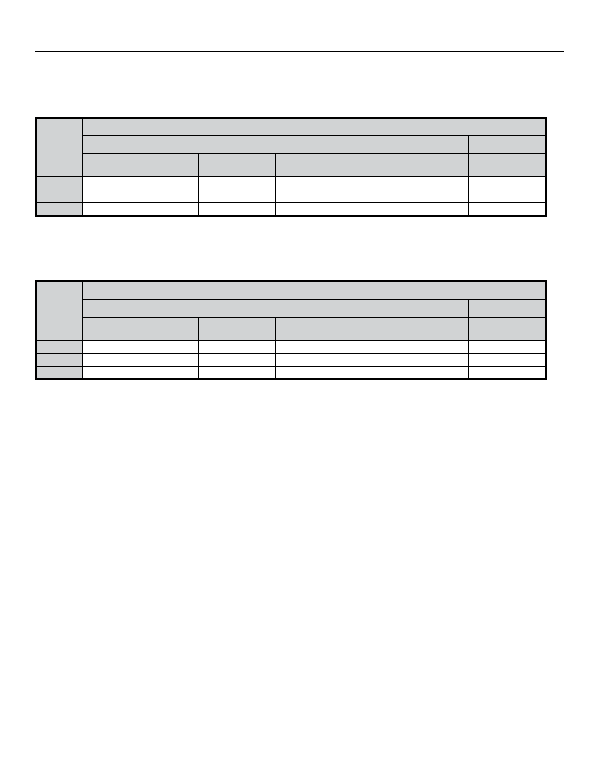
Performance Data
AHRI/ASHRAE/ISO 13256-1
ASHRAE/AHRI/ISO 13256-1. English (I-P) Units
Water Loop Heat Pump Ground Water Heat Pump Ground Loop Heat Pump
Model
HBH072 69,000 13.3 92,500 5.0 78,500 19.7 75,500 4.4 71,000 14.6 58,000 3.5
HBH096 95,000 13.7 123,000 5.0 104,500 20.0 101,000 4.4 98,000 15.2 77,000 3.6
HBH120 119,000 13.3 160,000 4.6 134,000 19.3 132,500 4.0 122,500 14.5 103,000 3.3
Note 1: All HBH072 ratings @ 2400CFM (1133 l/s) w/20GPM (1.26 l/s). Sheave setting for AHRI is 2.5 turns open.
Note 2: All HBH096 ratings @ 3200CFM (1510 l/s) w/24GPM (1.51 l/s). Sheave setting for AHRI is 3.0 turns open.
Note 3: All HBH120 ratings @ 4000CFM (1888 l/s) w/30GPM (1.89 l/s). Sheave setting for AHRI is 3.0 turns open.
Note 4: Cooling capacities based upon 80.6°F DB, 66.2°F WB entering air temperature.
Note 5: Heating capacities based upon 68°F DB, 59°F WB entering air temperature.
Note 6: All ratings based upon operation at lower voltage of dual voltage rated models.
Cooling 86°F Heating 68°F Cooling 59°F Heating 50°F Cooling 77°F Heating 32°F
Capacity
Btuh
EER
Btuh/W
Capacity
Btuh
COP
Capacity
Btuh
EER
Btuh/W
Capacity
Btuh
COP
Capacity
Btuh
EER
Btuh/W
Capacity
Btuh
Water Loop Heat Pump Ground Water Heat Pump Ground Loop Heat Pump
Model
HBH072 20,223 3.9 27,110 5.0 23,007 5.8 22,128 4.4 20,809 4.3 16,999 3.5
HBH096 27,843 4.0 36,049 5.0 30,627 5.9 29,601 4.4 28,722 4.5 22,567 3.6
HBH120 34,877 3.9 46,893 4.6 39,273 5.7 38,834 4.0 35,903 4.2 30,188 3.3
Cooling capacities based upon 80.6°F DB, 66.2°F WB entering air temperature.
Heating capacities based upon 68°F DB, 59°F WB entering air temperature.
All ratings based upon operation at lower voltage of dual voltage rated models
Cooling 30°C Heating 20°C Cooling 15°C Heating 10°C Cooling 25°C Heating 0°C
Capacity
Watts
EER W/W
Capacity
Watts
COP
Capacity
Watts
EER W/W
Capacity
Watts
COP
Capacity
Watts
EER W/W
Capacity
Watts
COP
Heating
COP
5
Page 8

Heat Controller, Inc. HBH SerieS Submittal Data
Heat Controller, Inc. HBH SERIES Engineering Design Guide
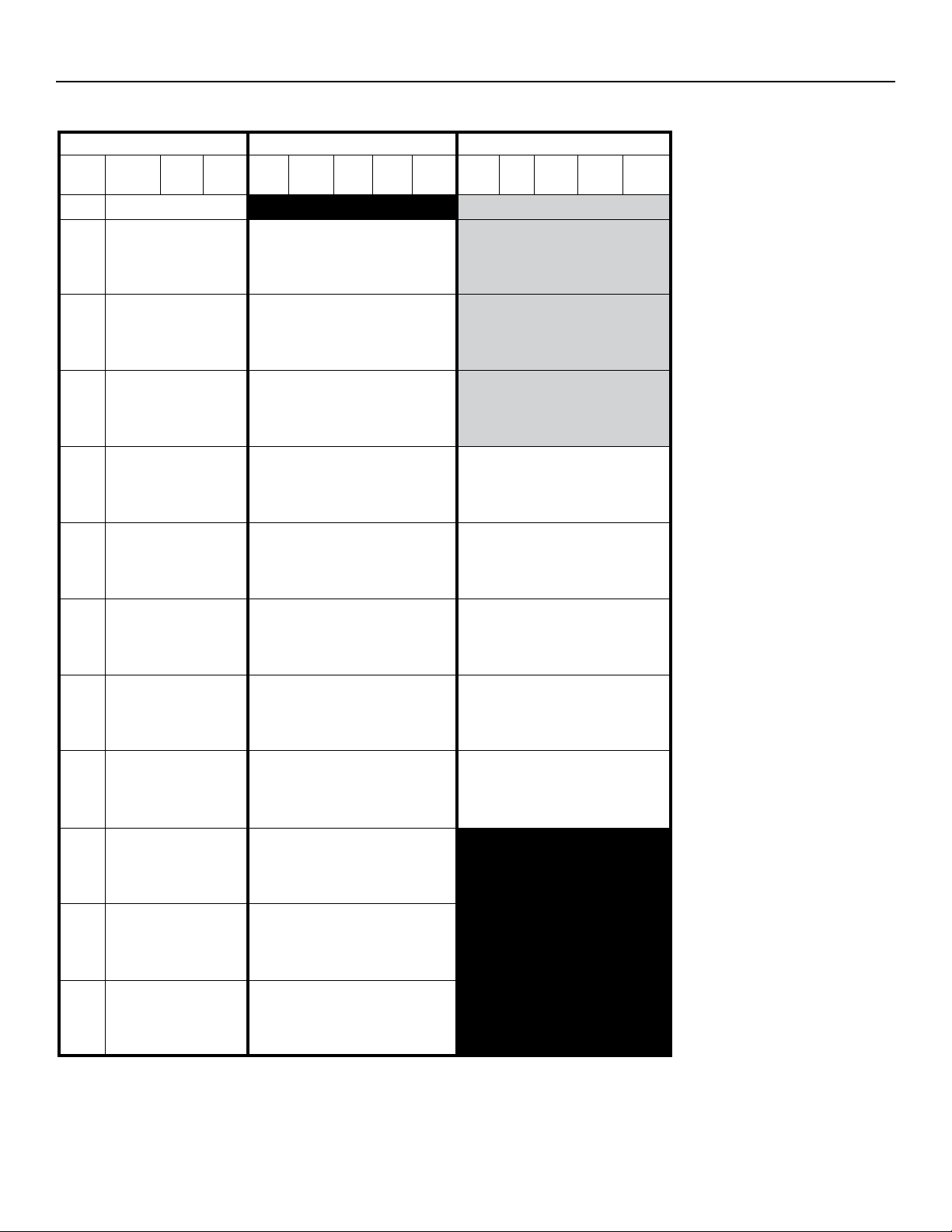
Performance Data
Selection Notes
For operation in the shaded area when water is used in lieu of
an anti-freeze solution, the LWT (Leaving Water Temperature)
must be calculated. Flow must be maintained to a level
such that the LWT is maintained above 42°F [5.6°C] when
the JW3 jumper is not clipped (see example below). This is
due to the potential of the refrigerant temperature being as
low as 32°F [0°C] with 40°F [4.4°C] LWT, which may lead to a
nuisance cutout due to the activation of the Low Temperature
Protection. JW3 should never be clipped for standard range
equipment or systems without antifreeze.
Example:
At 50°F EWT (Entering Water Temperature) and 1.5 gpm/ton, a
8 ton unit has a HE of 72,200 Btuh.
To calculate LWT, rearrange the formula for HE as follows:
HE = TD x GPM x 500, where HE = Heat of Extraction (Btuh); TD
= temperature dierence (EWT - LWT) and GPM = U.S. Gallons
per Minute.
EWT
°F
50
WATER/BRINE
FLOW
gpmPDpsi
12.0 1.7 4.0
18.0 4.5 10.3
24.0 7.9 18.2
HBH096
PD ft.
Heating - EAT 70°F
HC kW HE LAT COP
96.7 7.17 72.2 95.9 4.0
101.9 7.27 77.1 97.4 4.1
104.7 7.32 79.8 98.2 4.2
TD = HE / (GPM x 500)
TD = 72,200 / (12 x 500)
TD = 12°F
LWT = EWT - TD
LWT = 50 - 12 = 38°F - Antifreeze must be used
In this example, a higher ow rate will be required for EWTs at or below 50°F without antifreeze.
6
Page 9
Submittal Data HBH SerieS Heat Controller, Inc.
Engineering Design Guide HBH SERIES Heat Controller, Inc.
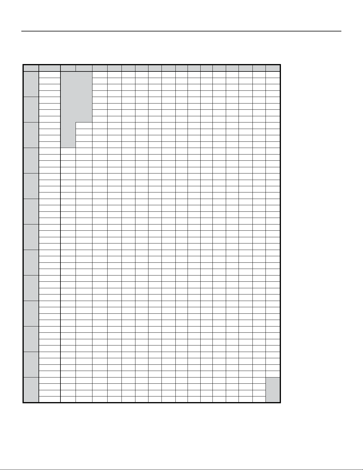
Performance Data: HBH072
Performance capacities shown in thousands of Btuh2400 CFM Nominal Airow Heating & Cooling
WATER/BRINE Cooling - EAT 80/67°F Heating - EAT 70°F
°F
20
30
40
50
60
70
80
85
90
100
110
120
FLOW
gpmPDpsi
20.00 6.8 15.8 Operation Not Recommended 49.5 5.0 32.5 87.1 2.9
10.00 1.2 2.7 82.3 56.8 3.6 94.5 23.0 54.7 5.0 37.5 89.0 3.2
15.00 3.3 7.7 81.1 55.8 3.4 92.8 23.6 56.8 5.1 39.6 89.9 3.3
20.00 6.2 14.3 80.2 55.1 3.4 91.7 23.8 58.0 5.1 40.7 90.3 3.4
10.00 1.0 2.2 82.4 57.4 3.9 95.6 21.2 63.2 5.1 45.6 92.3 3.6
15.00 3.0 7.0 82.6 57.1 3.7 95.1 22.4 66.1 5.2 48.4 93.4 3.7
20.00 5.6 13.0 82.4 56.8 3.6 94.6 22.9 67.7 5.2 50.0 94.1 3.8
10.00 0.9 2.0 80.7 57.2 4.2 95.1 19.0 72.3 5.3 54.4 95.8 4.0
15.00 2.8 6.5 81.9 57.4 4.0 95.6 20.5 76.0 5.3 57.8 97.2 4.2
20.00 5.3 12.2 82.3 57.4 3.9 95.6 21.1 78.0 5.4 59.7 98.0 4.3
10.00 0.5 1.2 77.7 56.3 4.7 93.6 16.7 81.8 5.4 63.3 99.5 4.4
15.00 2.2 5.1 79.7 56.9 4.4 94.7 18.2 86.0 5.5 67.2 101.1 4.6
20.00 4.4 10.1 80.6 57.2 4.3 95.1 18.9 88.3 5.5 69.4 102.0 4.7
10.00 0.5 1.1 73.9 54.9 5.2 91.4 14.3 91.1 5.6 72.0 103.1 4.8
15.00 2.1 4.8 76.3 55.8 4.8 92.8 15.8 95.6 5.7 76.3 104.8 4.9
20.00 4.2 9.6 77.5 56.2 4.69 93.5 16.5 98.0 5.7 78.5 105.7 5.0
10.00 0.4 0.9 69.4 53.1 5.71 88.9 12.2 99.8 5.8 80.2 106.4 5.1
15.00 1.9 4.5 72.2 54.2 5.37 90.5 13.4 104.4 5.9 84.4 108.2 5.2
20.00 3.9 9.1 73.5 54.7 5.20 91.2 14.1 106.7 5.9 86.5 109.1 5.3
10.00 0.4 0.8 67.1 52.1 6.03 87.7 11.2 103.7 5.8 83.8 107.9 5.2
15.00 1.9 4.4 69.8 53.3 5.66 89.2 12.4 108.0 5.9 87.8 109.6 5.3
20.00 3.9 8.9 71.2 53.8 5.49 89.9 13.0 110.1 6.0 89.7 110.4 5.4
10.00 0.3 0.8 64.8 51.2 6.35 86.4 10.2 107.6 5.9 87.4 109.4 5.3
15.00 1.8 4.3 67.5 52.3 5.96 87.9 11.3 111.7 6.0 91.1 111.0 5.4
20.00 3.8 8.8 68.9 52.9 5.78 88.6 11.9 113.5 6.0 92.8 111.7 5.5
10.00 0.3 0.7 60.1 49.2 7.06 84.2 8.5
15.00 1.8 4.1 62.7 50.3 6.64 85.4 9.4
20.00 3.7 8.5 64.1 50.9 6.44 86.1 10.0
10.00 0.2 0.6 55.8 47.5 7.87 82.7 7.1
15.00 1.7 3.9 58.1 48.4 7.41 83.4 7.8
20.00 3.6
10.00 0.2 0.5 52.2 46.3 8.78 82.2 5.9
15.00 1.6 3.7 54.1 46.9 8.27 82.3 6.5
20.00 3.5 8.0 55.1 47.3 8.02 82.5 6.9
PD ft. TC SC kW HR EER HC kW HE LAT COP
Operation Not Recommended
8.3 59.4 48.9 7.19 83.9 8.3
EWT
Interpolation is permissible; extrapolation is not.
All entering air conditions are 80°F DB and 67°F WB in cooling, and 70°F DB in heating.
AHRI/ISO certied conditions are 80.6°F DB and 66.2°F WB in cooling and 68°F DB in heating.
Table does not reect fan or pump power corrections for AHRI/ISO conditions.
All performance is based upon the lower voltage of dual voltage rated units.
Performance stated is at the rated power supply; performance may vary as the power supply varies from the rated.
Operation below 40°F EWT is based upon a 15% methanol antifreeze solution.
Operation below 60°F EWT requires optional insulated water/refrigerant circuit.
See performance correction tables for operating conditions other than those listed above.
See Performance Data Selection Notes for operation in the shaded areas.
7
Page 10

Heat Controller, Inc. HBH SerieS Submittal Data
Heat Controller, Inc. HBH SERIES Engineering Design Guide
Performance Data: HBH096
Performance capacities shown in thousands of Btuh3200 CFM Nominal Airow Heating & Cooling
WATER/BRINE Cooling - EAT 80/67°F Heating - EAT 70°F
°F
20
30
40
50
60
70
80
85
90
100
110
120
FLOW
gpmPDpsi
24.0 10.2 23.5 Operation Not Recommended 67.1 6.60 44.6 87.4 3.0
12.0 2.1 4.9 109.6 77.9 4.9 126.2 22.4 73.6 6.73 50.7 89.3 3.2
18.0 5.3 12.1 109.3 77.9 4.7 125.3 23.3 76.9 6.79 53.7 90.2 3.3
24.0 9.3 21.4 108.9 77.8 4.6 124.6 23.7 78.7 6.83 55.4 90.7 3.4
12.0 1.9 4.4 108.7 77.3 5.3 126.7 20.7 84.8 6.95 61.1 92.5 3.6
18.0 4.8 11.0 109.5 77.8 5.0 126.5 21.9 89.0 7.03 65.1 93.7 3.7
24.0 8.4 19.3 109.6 77.9 4.9 126.2 22.5 91.4 7.07 67.3 94.4 3.8
12.0 1.7 4.0 106.7 76.2 5.7 126.2 18.7 96.7 7.17 72.2 95.9 4.0
18.0 4.5 10.3 108.2 77.0 5.4 126.6 20.1 101.9 7.27 77.1 97.4 4.1
24.0 7.9 18.2 108.8 77.3 5.2 126.7 20.8 104.7 7.32 79.8 98.2 4.2
12.0 1.5 3.4 103.6 74.8 6.3 124.9 16.5 108.8 7.40 83.6 99.4 4.3
18.0 3.8 8.8 105.8 75.8 5.9 125.9 18.0 114.9 7.51 89.3 101.2 4.5
24.0 6.8 15.8 106.8 76.3 5.7 126.2 18.8 118.2 7.58 92.4 102.1 4.6
12.0 1.3 3.1 99.6 73.1 6.9 123.1 14.5 121.0 7.63 95.0 102.9 4.6
18.0 3.6 8.4 102.4 74.3 6.5 124.4 15.9 127.7 7.76 101.2 104.9 4.8
24.0 6.6 15.2 103.7 74.9 6.2 125.0 16.6 131.3 7.83 104.6 105.9 4.9
12.0 1.2 2.8 94.9 71.1 7.6 120.9 12.5 132.8 7.86 106.0 106.3 5.0
18.0 3.4 7.9 98.2 72.5 7.1 122.4 13.8 139.8 8.01 112.5 108.4 5.1
24.0 6.3 14.5 99.7 73.1 6.9 123.2 14.5 143.5 8.09 115.9 109.4 5.2
12.0 1.1 2.7 92.3 70.0 8.0 119.6 11.6 138.3 7.98 111.1 107.9 5.1
18.0 3.4 7.7 95.7 71.4 7.5 121.3 12.8 145.3 8.13 117.5 109.9 5.2
24.0 6.2 14.2 97.3 72.1 7.2 122.0 13.5 148.8 8.21 120.8 111.0 5.3
12.0 1.1 2.5 89.6 68.9 8.4 118.4 10.6 143.9 8.10 116.2 109.5 5.2
18.0 3.3 7.6 93.2 70.4 7.9 120.1 11.8 150.8 8.25 122.6 111.5 5.4
24.0 6.1 14.0 94.9 71.1 7.6 120.9 12.5 154.2 8.34 125.7 112.5 5.4
12.0 1.0 2.3 83.9 66.6 9.3 115.7 9.0
18.0 3.1 7.2 87.7 68.1 8.7 117.5 10.0
24.0 5.9 13.6 89.6 68.9 8.4 118.3 10.6
12.0 0.9 2.0 77.8 64.0 10.4 113.1 7.5
18.0 3.0 6.8 81.7 65.7 9.7 114.8 8.4
24.0 5.7
12.0 0.8 1.8 71.5 61.2 11.5 110.6 6.2
18.0 2.8 6.5 75.4 63.0 10.8 112.2 7.0
24.0 5.5 12.6 77.4 63.8 10.4 113.0 7.4
PD ft. TC SC kW HR EER HC kW HE LAT COP
Operation Not Recommended
13.1 83.7 66.5 9.4 115.6 8.9
EWT
Interpolation is permissible; extrapolation is not.
All entering air conditions are 80°F DB and 67°F WB in cooling, and 70°F DB in heating.
AHRI/ISO certied conditions are 80.6°F DB and 66.2°F WB in cooling and 68°F DB in heating.
Table does not reect fan or pump power corrections for AHRI/ISO conditions.
All performance is based upon the lower voltage of dual voltage rated units.
Performance stated is at the rated power supply; performance may vary as the power supply varies from the rated.
Operation below 40°F EWT is based upon a 15% methanol antifreeze solution.
Operation below 60°F EWT requires optional insulated water/refrigerant circuit.
See performance correction tables for operating conditions other than those listed above.
See Performance Data Selection Notes for operation in the shaded areas.
8
Page 11

Submittal Data HBH SerieS Heat Controller, Inc.
Engineering Design Guide HBH SERIES Heat Controller, Inc.
Performance Data: HBH120
Performance capacities shown in thousands of Btuh4000 CFM Nominal Airow Heating & Cooling
WATER/BRINE Cooling - EAT 80/67°F Heating - EAT 70°F
°F
20
30
40
50
60
70
80
85
90
100
110
120
FLOW
gpmPDpsi
30.00 16.0 36.9 Operation Not Recommended 91.8 9.0 61.1 89.2 3.0
15.00 4.0 9.2 141.5 98.1 6.6 163.9 21.6 99.2 9.2 67.8 90.9 3.2
22.50 8.6 19.9 140.4 98.2 6.3 162.0 22.2 103.3 9.3 71.6 91.9 3.3
30.00 14.5 33.4 139.2 98.0 6.2 160.5 22.4 105.6 9.4 73.7 92.4 3.3
15.00 3.5 8.0 140.6 97.2 7.0 164.4 20.1 112.5 9.5 80.1 94.0 3.5
22.50 7.7 17.8 141.5 98.0 6.7 164.2 21.3 117.8 9.6 84.9 95.2 3.6
30.00 13.0 30.0 141.5 98.2 6.5 163.7 21.7 120.8 9.7 87.6 95.9 3.6
15.00 3.2 7.4 137.4 95.6 7.5 163.0 18.3 126.8 9.9 93.2 97.3 3.8
22.50 7.2 16.6 139.9 96.8 7.1 164.1 19.7 133.3 10.0 99.2 98.8 3.9
30.00 12.2 28.3 140.8 97.3 6.9 164.4 20.3 136.9 10.1 102.5 99.6 4.0
15.00 2.4 5.5 132.6 93.5 8.1 160.3 16.3 141.7 10.2 106.9 100.7 4.1
22.50 5.8 13.4 136.2 95.0 7.7 162.4 17.7 149.3 10.4 114.0 102.5 4.2
30.00 10.2 23.6 137.7 95.8 7.5 163.2 18.5 153.6 10.5 117.9 103.5 4.3
15.00 2.2 5.1 126.6 90.9 8.9 156.9 14.3 156.8 10.5 120.9 104.2 4.4
22.50 5.5 12.7 130.9 92.8 8.3 159.4 15.7 165.6 10.7 129.0 106.2 4.5
30.00 9.8 22.6 133.0 93.6 8.1 160.6 16.4 170.4 10.8 133.4 107.3 4.6
15.00 2.1 4.7 119.9 88.0 9.7 153.1 12.3 172.0 10.9 135.0 107.7 4.6
22.50 5.2 12.0 124.6 90.0 9.1 155.7 13.7 181.6 11.1 143.8 110.0 4.8
30.00 9.4 21.7 126.9 91.0 8.8 157.1 14.4 186.9 11.2 148.6 111.2 4.9
15.00 2.0 4.6 116.4 86.5 10.2 151.2 11.5 179.5 11.0 141.9 109.5 4.8
22.50 5.1 11.9 121.1 88.5 9.6 153.8 12.7 189.4 11.3 151.0 111.7 4.9
30.00 9.3 21.5 123.5 89.6 9.3 155.1 13.4 194.8 11.4 155.8 113.0 5.0
15.00 2.0 4.5 113.0 85.0 10.7 149.3 10.6 187.0 11.2 148.7 111.2 4.9
22.50 5.1 11.7 117.7 87.0 10.0 151.8 11.8 197.2 11.5 158.1 113.5 5.0
30.00 9.2 21.2 120.1 88.1 9.7 153.2 12.4 202.7 11.6 163.1 114.8 5.1
15.00 1.9 4.3 106.0 81.8 11.7 146.0 9.0
22.50 4.9 11.4 110.6 83.9 11.0 148.1 10.0
30.00 9.0 20.8 112.9 84.9 10.7 149.3 10.6
15.00 1.8 4.1 99.6 78.9 12.9 143.6 7.7
22.50 4.8 11.1 103.7 80.8 12.1 145.0 8.6
30.00 8.8
15.00 1.7 3.9 94.2 76.5 14.2 142.6 6.6
22.50 4.7 10.8 97.5 78.0 13.4 143.1 7.3
30.00 8.6 19.9 99.4 78.8 13.0 143.5 7.7
PD ft. TC SC kW HR EER HC kW HE LAT COP
Operation Not Recommended
20.4 105.9 81.8 11.8 145.9 9.0
EWT
Interpolation is permissible; extrapolation is not.
All entering air conditions are 80°F DB and 67°F WB in cooling, and 70°F DB in heating.
AHRI/ISO certied conditions are 80.6°F DB and 66.2°F WB in cooling and 68°F DB in heating.
Table does not reect fan or pump power corrections for AHRI/ISO conditions.
All performance is based upon the lower voltage of dual voltage rated units.
Performance stated is at the rated power supply; performance may vary as the power supply varies from the rated.
Operation below 40°F EWT is based upon a 15% methanol antifreeze solution.
Operation below 60°F EWT requires optional insulated water/refrigerant circuit.
See performance correction tables for operating conditions other than those listed above.
See Performance Data Selection Notes for operation in the shaded areas.
9
Page 12

Heat Controller, Inc. HBH SerieS Submittal Data
Heat Controller, Inc. HBH SERIES Engineering Design Guide
HBH Performance Data
Correction Tables
Air Flow Correction Table
Percentage
of Rated
Airow
75% 0.957 0.869 0.951 0.955 0.970 1.054 0.964
81% 0.966 0.901 0.963 0.966 0.978 1.035 0.975
88% 0.976 0.933 0.974 0.976 0.986 1.017 0.987
94% 0.988 0.966 0.987 0.988 0.993 1.009 0.993
100% 1.000 1.000 1.000 1.000 1.000 1.000 1.000
106% 1.006 1.029 1.014 1.008 1.006 0.999 1.005
113% 1.012 1.058 1.027 1.015 1.012 0.997 1.010
119% 1.017 1.080 1.051 1.024 1.017 0.996 1.014
125% 1.022 1.103 1.074 1.033 1.022 0.996 1.019
Total
Capacity
Cooling Heating
Sensible
Capacity
Power
Heat of
Rejection
Heating
Capacity
Power
Heat of
Extraction
HBH072-120 Entering Air Correction Table Cooling
Entering
Air WB°F
50 0.7335 0.8825 * * * * * * * * 0.9782 0.7834
55 0.8063 0.6757 0.8842 1.1119 * * * * * * 0.9836 0.8424
60 0.8830 0.6734 0.8817 1.0918 * * * * * 0.9900 0.9301
65 0.9774 0.6682 0.8764 1.0885 1.1136 1.2949 * * 0.9973 0.9981
66.2 0.9851 0.6177 0.8243 1.0357 1.0612 1.2452 * * 0.9987 0.9879
67 1.0000 0.5842 0.7897 1.0000 1.0262 1.2119 * * 1.0000 1.0000
70 1.0426 0.6609 0.8688 0.8941 1.0811 1.2916 * 1.0043 1.0420
75 1.1386 0.6517 0.6517 0.8594 1.0695 1.2838 1.0118 1.1128
Total
Capacity
60 65 70 75 80 80.6 85 90 95
Sensible Cooling Capacity Multiplier - Entering DB °F
Power
Heat of
Rejection
* = Sensible capacity equals total capacity
AHRI/ISO/ASHRAE 13256-1 uses entering air conditions of Cooling - 80.6°F DB/66.2°F WB, 1
and Heating - 68°F DB/59°F WB entering air temperature
Entering Air Correction Table
Entering
Air DB°F
50 1.044 0.834 1.099
55 1.034 0.872 1.076
60 1.024 0.910 1.053
65 1.012 0.955 1.027
68 1.005 0.982 1.011
70 1.000 1.000 1.000
75 0.989 1.047 0.974
80 0.974 1.101 0.942
Heating
Capacity
Power
Heat of
Extraction
10
Page 13

Submittal Data HBH SerieS Heat Controller, Inc.
Engineering Design Guide HBH SERIES Heat Controller, Inc.
Antifreeze Correction Table
Antifreeze Type
Water
Propylene Glycol
Methanol
Ethanol
Ethylene Glycol
Antifreeze
%
EWT 90°F EWT 30°F
Total Cap Sens Cap Power Htg Cap Power
0 1.000 1.000 1.000
5 0.995 0.995 1.003 0.989 0.997 1.070
15 0.986 0.986 1.009 0.968 0.990 1.210
25 0.978 0.978 1.014 0.947 0.983 1.360
5 0.995 0.995 1.002 0.989 0.997 1.070
15 0.990 0.990 1.007 0.968 0.990 1.160
25 0.982 0.982 1.012 0.949 0.984 1.220
5 0.998 0.998 1.002 0.981 0.994 1.140
15 0.994 0.994 1.005 0.944 0.983 1.300
25 0.986 0.986 1.009 0.917 0.974 1.360
5 0.998 0.998 1.002 0.993 0.998 1.040
15 0.994 0.994 1.004 0.980 0.994 1.120
25 0.988 0.988 1.008 0.966 0.990 1.200
Cooling Heating
WPD
Corr. Fct.
EWT 30°F
11
Page 14
Heat Controller, Inc. HBH SerieS Submittal Data
Heat Controller, Inc. HBH SERIES Engineering Design Guide
Blower Performance Data
HBH072 - Standard Unit
All Data is Wet Coil
SCFM ESP 0.00 0.10 0.20 0.30 0.40 0.50 0.60 0.70 0.80 0.90 1.00 1.10 1.20 1.30 1.40 1.50
BHP 0.28 0.32 0.35 0.39 0.42 0.45 0.48 0.52 0.56 0.60 0.64 0.69 0.72 0.76
Sheave/Mtr B B B A A A A A A C C C C C
1800
1900
2000
2100
2200
2300
2400
2500
2600
2700
2800
2900
3000
A = Standard Static/Standard Motor, B = Low Static/Standard Motor, C = High Static/Standard Motor, D = Standard Static/Large Motor, E = High Static/Large Motor
Unit factory shipped with standard static sheave and drive at 2.5 turns open. Other speed require eld selection.
For applications requiring higher static pressures, contact your local representative. Performance data does not include drive losses and is based on sea level conditions.
Do not operate in black regions. All airow is rated at lowest Voltage if unit is dual Voltage rated, i.e. 208V for 208-230V units.
RPM 599 645 690 735 775 815 850 885 910 940 965 995 1015 1040
Turns Open 3 2 1 4 3.5 2.5 2 1.5 1 5 4.5 4 3.5 3
BHP 0.31 0.36 0.40 0.44 0.49 0.53 2.50 0.62 0.65 0.69 0.73 0.76 0.80 0.84
Sheave/Mtr B B A A A A A A C C C C C C
RPM 604 655 695 740 780 820 855 890 920 950 980 1005 1030 1055
Turns Open 3 2 5 4 3 2.5 2 1.5 5.5 4.5 4 3.5 3 3
BHP 0.31 0.34 0.39 0.45 0.50 0.54 0.59 0.63 0.67 0.72 0.75 0.79 0.82 0.86 0.90
Sheave/Mtr B B B A A A A A A C C C C C C
RPM 568 615 660 705 750 785 825 860 895 930 960 990 1015 1040 1065
Turns Open 4.5 2.5 1.5 4.5 3.5 3 2.5 1.5 1 5 4.5 4 3.5 3 2.5
BHP 0.33 0.38 0.42 0.46 0.50 0.54 0.59 0.65 0.70 0.74 0.78 0.81 0.85 0.89 0.94 0.98
Sheave/Mtr B B B A A A A A A A C C C C C C
RPM 531 583 630 670 715 755 795 835 875 905 940 970 1000 1025 1055 1080
Turns Open 4.5 3.5 2 5 4.5 3.5 2.5 2 1.5 1 5 4 4 3 2.5 2.5
BHP 0.37 0.40 0.45 0.49 0.55 0.60 0.65 0.70 0.75 0.79 0.83 0.87 0.92 0.96 1.00 1.04
Sheave/Mtr B B B A A A A A A C C C C C E E
RPM 552 599 645 685 730 770 810 850 885 915 950 980 1010 1040 1065 1090
Turns Open 4 3 2 5 4 3 2.5 2 1.5 5.5 4.5 4 3.5 3 2.5 2
BHP 0.42 0.47 0.51 0.56 0.60 0.65 0.70 0.75 0.80 0.84 0.89 0.94 1.00 1.05 1.10 1.16
Sheave/Mtr B B B A A A A A A C C C E E E E
RPM 573 620 660 705 745 785 820 860 895 925 960 990 1020 1050 1075 1105
Turns Open 3.5 2.5 1.5 4.5
BHP 0.48 0.52 0.57 0.61 0.66 0.72 0.78 0.83 0.87 0.92 0.97 1.02 1.07 1.13 1.19 1.25
Sheave/Mtr B B A A A A A A A C C E E E E E
RPM 604 645 690 730 765 805 845 880 910 945 975 1010 1035 1065 1095 1125
Turns Open 3 2 5 4 3.5 2.5 2 1.5 1 5 4 3.5 3 2.5 2 1.5
BHP 0.52 0.57 0.61 0.66 0.72 0.78 0.83 0.89 0.94 1.00 1.03 1.08 1.14 1.20 1.25 1.31
Sheave/Mtr B B A A A A A A C E E E E E E E
RPM 620 660 700 740 780 815 850 885 920 950 985 1015 1045 1075 1100 1130
Turns Open 2.5 1.5 4.5 4 3 2.5 2 1.5 5.5 4.5 4 3.5 3 2.5 2 1.5
BHP 0.56 0.61 0.66 0.70 0.76 0.82 0.88 0.93 0.98 1.04 1.08 1.14 1.20 1.26 1.32 1.37
Sheave/Mtr B A A A A A A A C E E E E E E E
RPM 635 675 715 750 790 825 860 895 925 960 990 1020 1050 1080 1110 1135
Turns Open 2.5 5 4.5 3.5 3 2 1.5 1 5 4.5 4 3.5 3 2.5 1.5 1.5
BHP 0.61 0.66 0.71 0.76 0.82 0.87 0.93 0.98 1.04 1.10 1.15 1.21 1.27 1.33 1.39 1.45
Sheave/Mtr B A A A A A A A E E E E E E E E
RPM 655 695 730 770 805 840 875 905 940 970 1000 1030 1060 1090 1120 1145
Turns Open 2 4.5 4 3.5 2.5 2 1.5 1 5 4.5 3.5 3 2.5 2 1.5 1
BHP 0.66 0.72 0.77 0.83 0.88 0.93 0.99 1.05 1.11 1.16 1.22 1.30 1.37 1.44 1.51 1.57
Sheave/Mtr B A A A A A A D E E E E E E E E
RPM 670 710 750 785 815 850 885 915 950 980 1010 1040 1070 1100 1130 1155
Turns Open 1.5 4.5 3.5 3 2.5 1.5 1.5 1 4.5 4 3.5 3 2.5 2 1.5 1
BHP 0.71 0.77 0.82 0.87 0.93 0.98 1.04 1.10 1.16 1.22 1.30 1.36 1.43 1.50 1.57 1.63
Sheave/Mtr A A A A A A D E E E E E E E E E
RPM 685 725 765 795 830 860 895
Turns Open 5 4 3.5 3 2 1.5 1 5 4.5 4 3.5 3 2.5 1.5 1 1
BHP 0.79 0.84 0.90 0.95 1.01 1.07 1.13 1.19 1.25 1.31 1.38 1.46 1.52 1.59 1.66
Sheave/Mtr A A A A A D D E E E E E E E E
RPM 710 745 780 815 850 885 915 945 975 1005 1035 1065 1090 1120 1150
Turns Open 4.5 4 3 2.5 2 1 1 5 4 3.5 3 2.5 2 1.5 1
4 3 2.5 1.5 1 5 4.5 4 3.5 3 2.5 2
925 955 985 1020 1045 1075 1105 1135 1160
12
Page 15

Submittal Data HBH SerieS Heat Controller, Inc.
Engineering Design Guide HBH SERIES Heat Controller, Inc.
Blower Performance Data
HBH096 - Standard Unit
All Data is Wet Coil
SCFM ESP 0.00 0.10 0.20 0.30 0.40 0.50 0.60 0.70 0.80 0.90 1.00 1.10 1.20 1.30 1.40 1.50
BHP 0.45 0.50 0.54 0.59 0.63 0.69 0.74 0.80 0.85 0.90 0.94 0.99 1.04 1.10 1.16 1.22
Sheave/Mtr B B B B B A A A A A A A A A C C
2400
2500
2600
2700
2800
2900
3000
3100
3200
A = Standard Static/Standard Motor, B = Low Static/Standard Motor, C = High Static/Standard Motor, D = Standard Static/Large Motor, E = High Static/Large Motor
Unit factory shipped with standard static sheave and drive at 2.5 turns open. Other speed require eld selection.
For applications requiring higher static pressures, contact your local representative. Performance data does not include drive losses and is based on sea level conditions.
Do not operate in black regions. All airow is rated at lowest Voltage if unit is dual Voltage rated, i.e. 208V for 208-230V units.
RPM 578 625 665 705 745 785 820 860 895 925 960 990 1020 1050 1080 111 0
Turns
Open
BHP 0.50 0.55 0.59 0.64 0.69 0.75 0.81 0.88 0.92 0.97 1.01 1.06 1.12 1.17 1.23 1.29
Sheave/Mtr B B B B A A A A A A A A A C C C
RPM 599 645 685 725 765 800 835 875 905 940 970 1005 1035 1060 1090 1120
Turns
Open
BHP 0.55 0.60 0.65 0.69 0.75 0.80 0.86 0.92 0.97 1.02 1.08 1.13 1.19 1.25 1.30 1.36
Sheave/Mtr B B B B A A A A A A A A A C C C
RPM 625 665 705 740 780 815 850 885 920 950 985 1015 1045 1075 1100 1130
Turns
Open
BHP 0.60 0.65 0.70 0.75 0.80 0.86 0.91 0.97 1.02 1.08 1.14 1.20 1.26 1.32 1.38 1.44
Sheave/Mtr B B B A A A A A A A A A C C C C
RPM 645 685 725 760 795 830 865 900 930 960 995 1025 1055 1085 1115 1140
Turns
Open
BHP 0.65 0.71 0.76 0.82 0.87 0.93 0.98 1.04 1.10 1.16 1.21 1.28 1.36 1.43 1.50 1.56
Sheave/Mtr B B B A A A A A A A A A C C C C
RPM 665 705 745 780 810 845 880 910 945 975 1005 1035 1065 1095 1125 1150
Turns
Open
BHP 0.71 0.76 0.82 0.87 0.92 0.98 1.03 1.09 1.16 1.22 1.29 1.36 1.43 1.50 1.57 1.63
Sheave/Mtr B B A A A A A A A A A A C
RPM 685 720 760 795 825 860 890 920 955 985 1015 1045 1075 1105 1135 1160
Turns
Open
BHP 0.78 0.84 0.89 0.95 1.00 1.06 1.12 1.18 1.24 1.30 1.37 1.43 1.50 1.58 1.64 1.71
Sheave/Mtr B B A A A A A A A A A C C C C C
RPM 700 740 775 810 845 880 910 940 970 1000 1030 1055 1085 1115 1140 1170
Turns
Open
BHP 0.85 0.91 0.96 1.02 1.08 1.14 1.22 1.29 1.36 1.44 1.50 1.57 1.63 1.70 1.76 1.82
Sheave/Mtr B B A A A A A A A A A C C C C C
RPM 720 755 790 825 860 890 925 955 985 1015 1040 1070 1095 1125 1150 1175
Turns
Open
BHP 0.93 1.00 1.07 1.14 1.20 1.26 1.32 1.38 1.44 1.51 1.57 1.64 1.70 1.78 1.85 1.92
Sheave/Mtr B A A A A A A A A A C C C C C C
RPM 740 775 810 845 875 905 935 965 995 1025 1050 1080 1105 1135 1160 1185
Turns
Open
5 4 3 2.5 1.5 5.5 5 4 3.5 3 2.5 2 1.5 1 4 3.5
4.5 3.5 2.5 2 6 5 4.5 4 3.5 3 2.5 2 1 4.5 3.5 3
4 3 2.5 1.5 5.5 5 4.5 3.5 3 2.5 2 1.5 1 4 3.5 3
3.5 2.5 2 6 5.5 4.5 4 3.5 3 2.5 2 1.5 4.5 4 3.5 3
3 2.5 1.5 5.5 5 4.5 4 3 2.5 2 1.5 1 4 3.5 3 2.5
C C C
2.5 2 6 5.5 5 4 3.5 3 2.5 2 1.5 1 4 3.5 3 2.5
2.5 1.5 5.5 5 4.5 4 3.5 2.5 2 1.5 1 4.5 3.5 3.5 3 2.5
2 1 5.5 4.5 4 3.5 3 2.5 2 1.5 1 4 3.5 3 2.5 2
1.5 5.5 5 4.5 4 3.5 3 2 1.5 1 4.5 4 3.5 3 2.5 2
Table Continued on Next Page
13
Page 16

Heat Controller, Inc. HBH SerieS Submittal Data
Heat Controller, Inc. HBH SERIES Engineering Design Guide
Blower Performance Data
HBH096 - Standard Unit
Table Continued from Previous Page
All Data is Wet Coil
SCFM ESP 0.00 0.10 0.20 0.30 0.40 0.50 0.60 0.70 0.80 0.90 1.00 1.10 1.20 1.30 1.40 1.50
BHP 1.01 1.08 1.14 1.21 1.28 1.33 1.39 1.45 1.51 1.58 1.64 1.72 1.78 1.84 1.93 2.00
Sheave/Mtr B A A A A A A A A A C C C C C E
3300
3400
3500
3600
3700
3800
3900
4000
A = Standard Static/Standard Motor, B = Low Static/Standard Motor, C = High Static/Standard Motor, D = Standard Static/Large Motor, E = High Static/Large Motor
Unit factory shipped with standard static sheave and drive at 2.5 turns open. Other speed require eld selection.
For applications requiring higher static pressures, contact your local representative. Performance data does not include drive losses and is based on sea level conditions.
Do not operate in black regions. All airow is rated at lowest Voltage if unit is dual Voltage rated, i.e. 208V for 208-230V units.
RPM 755 790 820 855 890 915 945 975 1005 1035 1060 1090 111 5 1140 1170 1195
Turns
Open
BHP 1.08 1.15 1.22 1.29 1.35 1.41 1.47 1.53 1.59 1.68 1.75 1.83 1.90 1.96 2.02 2.08
Sheave/Mtr A A A A A A A A A A C C C C E E
RPM 765 800 835 870 900 930 960 990 1015 1045 1070 1100 1125 1150 1175 1200
Turns
Open
BHP 1.16 1.23 1.29 1.36 1.42 1.48 1.54 1.60 1.66 1.73 1.79 1.85 1.92 2.01 2.09 2.17
Sheave/Mtr A A A A A A A A A C C C C E E E
RPM 780 815 845 880 910 940 970 1000 1025 1055 1080 1105 1130 1160 1185 1210
Turns
Open
BHP 1.24 1.30 1.37 1.44 1.51 1.58 1.65 1.72 1.78 1.86 1.92 1.98 2.06 2.13 2.21 2.29
Sheave/Mtr A A A A A A A A A C C C E E E E
RPM 795 825 860 890 920 950 980 1010 1035 1065 1090 111 5 1145 1165 1190 1215
Turns
Open
BHP 1.34 1.40 1.46 1.53 1.61 1.68 1.75 1.82 1.90 1.97 2.06 2.13 2.21 2.28 2.36 2.44
Sheave/Mtr A A A A A A A A C C E E E E E E
RPM 820 850 880 910 940 970 1000 1025 1055 1080 1110 1135 1160 1180 1205 1230
Turns
Open
BHP 1.43 1.49 1.56 1.63 1.70 1.78 1.86 1.94 2.02 2.12 2.20 2.28 2.34 2.42 2.50 2.58
Sheave/Mtr A A A A A A A A E E E E E
RPM 840 870 900 930 960 990 1020 1045 1070 1100 1125 1150 1170 1195 1220 1245
Turns
Open
BHP 1.58 1.64 1.71 1.78 1.85 1.93 2.01 2.09 2.19 2.27 2.35 2.41 2.49 2.57 2.65
Sheave/Mtr A A A A A A D D E E E E E E E
RPM 865 890 920 950 980 1010 1035 1060 1090 1115 1140 1160 1185 1210 1235
Turns
Open
BHP 1.68 1.75 1.83 1.92 2.00 2.08 2.16 2.26 2.34 2.42 2.50 2.56 2.64 2.72 2.80
Sheave/Mtr A A A A D D D E E E E E E E E
RPM 885 910 940 970 1000 1025 1050 1080 1105 1130 1155 1175 1200 1225 1250
Turns
Open
1 5.5 5 4 3.5 3 2.5 2 1.5 1 4 3.5 3 3 2.5 2
6 5 4.5 4 3.5 3 2.5 2 1.5 1 4 3.5 3 2.5 2 2
5.5 5 4.5 3.5 3 2.5 2 1.5 1 4.5 4 3.5 3 2.5 2 1.5
5.5 4.5 4 3.5 3 2.5 2 1.5 1 4 3.5 3 2.5 2.5 2 1.5
5 4.5 3.5 3 2.5 2 1.5 1 4.5 4 3.5 3 2.5 2 1.5 1.5
E E E
4.5 4 3.5 3 2.5 2 1.5 1 4 3.5 3 2.5 2.5 2 1.5 1
4 4 3 2.5 2 1.5 1 1 4 3.5 3 2.5 2 1.5 1.5
4 3.5 2.5 2.5 2 1 1 4 3.5 3 2.5 2 2 1.5 1
14
Page 17

Submittal Data HBH SerieS Heat Controller, Inc.
Engineering Design Guide HBH SERIES Heat Controller, Inc.
Blower Performance Data
HBH120 - Standard Unit
All Data is Wet Coil
SCFM ESP 0.00 0.10 0.20 0.30 0.40 0.50 0.60 0.70 0.80 0.90 1.00 1.10 1.20 1.30 1.40 1.50
BHP 0.75 0.81 0.86 0.91 0.97 1.03 1.09 1.15 1.21 1.27 1.34 1.41 1.47 1.54 1.61 1.67
Sheave/Mtr B B B B B B A A A A A A A A A A
3000
3100
3200
3300
3400
3500
3600
3700
3800
3900
4000
4100
4200
A = Standard Static/Standard Motor, B = Low Static/Standard Motor, C = High Static/Standard Motor, D = Standard Static/Large Motor, E = High Static/Large Motor
Unit factory shipped with standard static sheave and drive at 2.5 turns open. Other speed require eld selection.
For applications requiring higher static pressures, contact your local representative. Performance data does not include drive losses and is based on sea level conditions.
Do not operate in black regions. All airow is rated at lowest Voltage if unit is dual Voltage rated, i.e. 208V for 208-230V units.
RPM 680 720 755 790 825 860 895 925 955 985 1015 1045 1070 1100 1130 1155
Turns Open 5 4 3.5 3 2.5 1.5 5.5 5 4.5 4 3.5 3 2.5 2 1.5 1
BHP 0.82 0.88 0.94 0.99 1.04 1.10 1.17 1.26 1.33 1.40 1.46 1.53 1.59 1.66 1.72 1.80
Sheave/Mtr B B B B B A A A A A A A A A A C
RPM 700 735 775 805 840 875 905 940 970 1000 1025 1055 1080 1110 1135 1165
Turns Open 4.5 4 3 2.5 2 6 5.5 4.5 4.5 3.5 3 3 2.5 2 1.5 4
BHP 0.90 0.96 1.03 1.10 1.17 1.23 1.29 1.35 1.41 1.47 1.55 1.61 1.68 1.74 1.81 1.89
Sheave/Mtr B B B B B A A A A A A A A A A C
RPM 720 755 790 825 860 890 920 950 980 1010 1040 1065 1095 1120 1145 1175
Turns Open 4 3.5 3 2 1.5 5.5 5 4.5 4 3.5 3 2.5 2 1.5 1 3.5
BHP 0.98 1.04 1.11 1.18 1.25 1.31 1.37 1.43 1.49 1.55 1.62 1.68 1.75 1.81 1.88 1.95
Sheave/Mtr B B B B A A A A A A A A A A A C
RPM 740 770 805 840 875 905 935 965 995 1020 1050 1075 1105 1130 1155 1180
Turns Open 4 3 2.5 2 6 5.5 5 4 4 3 2.5 2.5 2 1.5 1 3.5
BHP 1.06 1.13 1.19 1.26 1.33 1.38 1.44 1.50 1.56 1.65 1.72 1.80 1.87 1.94 2.00 2.06
Sheave/Mtr B B B B A A A A A A A A A A C C
RPM 755 790 820 855 890 915 945 975 1005 1035 1060 1090 111 5 1140 1165 1190
Turns Open 3.5 3 2.5 1.5 6 5 4.5 4 3.5 3 2.5 2 1.5 1 4 3
BHP 1.14 1.21 1.27 1.34 1.40 1.46 1.52 1.58 1.65 1.71 1.77 1.84 1.90 1.98 2.06 2.14
Sheave/Mtr B B B A A A A A A A A A A A C C
RPM 770
Turns Open 3 2.5 2 6 5.5 5 4.5 3.5 3.5 3 2.5 2 1.5 1 3.5 3
BHP 1.23 1.29 1.36 1.42 1.50 1.57 1.64 1.71 1.77 1.84 1.90 1.96 2.05 2.13 2.21 2.27
Sheave/Mtr B B B A A A A A A A A A A C C C
RPM 790 820 855 885 915 945 975 1005 1030 1060 1085 111 0 1140 1165 1190 1210
Turns Open 3 2.5 1.5 6 5.5 4.5 4 3.5 3 2.5 2 1.5 1.5 4 3.5 3
BHP 1.32 1.38 1.44 1.51 1.58 1.65 1.73 1.81 1.88 1.96 2.03 2.10 2.18 2.26 2.34 2.42
Sheave/Mtr B B A A A A A A A A A A A C C C
RPM 810 840 870 900 930 960 990 1020 1045 1075 1100 1125 1150 1175 1200 1225
Turns Open 2.5 2 6 5.5 5 4.5 4 3 3 2.5 2 1.5 1 3.5 3 2.5
BHP 1.41 1.47 1.54 1.61 1.68 1.75 1.82 1.91 1.99 2.07 2.17 2.25 2.31 2.39 2.47 2.55
Sheave/Mtr B B A A A A A A A A A A A C C C
RPM 830 860 890 920 950 980 1005 1035 1060 1085 1115 1140 1160 1185 1210 1235
Turns Open 2 1.5 5.5 5 4.5 4 3.5 3 2.5 2 1.5 1 1 3.5 3 2.5
BHP 1.54 1.60 1.67 1.74 1.82 1.89 1.96 2.04 2.14 2.22 2.30 2.38 2.46 2.52 2.60 2.68
Sheave/Mtr B A A A A A A A A A A A C C C C
RPM 850 875 905 935 965 995 1020 1045 1075 1100 1125 1150 1175 1195 1220 1245
Turns Open 2 6 5.5 5 4.5 3.5 3 2.5 2.5 2 1.5 1 3.5 3 2.5 2
BHP 1.63 1.71 1.78 1.86 1.94 2.03 2.11 2.19 2.27 2.37 2.45 2.51 2.59 2.67 2.75 2.85
Sheave/Mtr A A A A A A A A A A A A C C C C
RPM 865 895 920 950 980 1010 1035 1060 1085 1115 1140 1160 1185 1210 1235 1260
Turns Open 6 5.5 5 4.5 4 3.5 3 2.5 2 1.5 1 1 3.5 3 2.5 2
BHP 1.73 1.81 1.90 1.97 2.05 2.12 2.20 2.27 2.34 2.42 2.52 2.62 2.70 2.80 2.90
Sheave/Mtr A A A A A
RPM 885 915 945 970 1000 1025 1055 1080 1105 1130 1155 1180 1200 1225 1250
Turns Open 6 5.5 4.5 4 4 3 2.5 2 2 1.5 1 3.5 3 2.5 2
BHP 1.87 1.94 2.02 2.08 2.16 2.24 2.32 2.40 2.48 2.58 2.68 2.76 2.86 2.96
Sheave/Mtr A A A A A A A A A A C C C C
RPM 905 935 965 990 1020 1045 1070 1095 1120 1145 1170 1190 1215 1240
Turns Open 5.5 5 4.5 4 3.5 3 2.5 2 1.5 1 3.5 3.5 3 2.5
805 835 870 900 930 960 990 1020 1045 1070 1100 1125 1150 1175 1200
A A A A A A C C C C
Table Continued on Next Page
15
Page 18

Heat Controller, Inc. HBH SerieS Submittal Data
Heat Controller, Inc. HBH SERIES Engineering Design Guide
Blower Performance Data
HBH120 - Standard Unit
Table Continued from Previous Page
All Data is Wet Coil
SCFM ESP 0.00 0.10 0.20 0.30 0.40 0.50 0.60 0.70 0.80 0.90 1.00 1.10 1.20 1.30 1.40 1.50
BHP 2.00 2.07 2.16 2.23 2.31 2.41 2.49 2.57 2.66 2.74 2.84 2.94 3.02 3.15
Sheave/Mtr A A A A A A A A A C C C E E
4300
4400
4500
4600
4700
4800
4900
5000
A = Standard Static/Standard Motor, B = Low Static/Standard Motor, C = High Static/Standard Motor, D = Standard Static/Large Motor, E = High Static/Large Motor
Unit factory shipped with standard static sheave and drive at 2.5 turns open. Other speed require eld selection.
For applications requiring higher static pressures, contact your local representative. Performance data does not include drive losses and is based on sea level conditions.
Do not operate in black regions. All airow is rated at lowest Voltage if unit is dual Voltage rated, i.e. 208V for 208-230V units.
RPM 930 955 985 1010 1035 1065 1090 1115 1140 1160 1185 1210 1230 1255
Turns Open 5 4.5 4 3.5 3 2.5 2 1.5 1.5 4 3.5 3 2.5 2
BHP 2.14 2.22 2.32 2.40 2.48 2.56 2.65 2.74 2.82 2.92 3.00 3.10 3.18
Sheave/Mtr A A A A A A A A A C E E E
RPM 950 975 1005 1030 1055 1080 1110 1135 1155 1180 1200 1225 1245
Turns Open 4.5 4 3.5 3 3 2.5 2 1.5 1 4 3 3 2.5
BHP 2.30 2.38 2.46 2.54 2.62 2.72 2.80 2.88 3.00 3.08 3.16 3.26
Sheave/Mtr A A A A A A A A D E E E
RPM 970 995 1020 1045 1070 1100 1125 1145 1170 1195 1215 1240
Turns Open 4.5 4 3.5 3 2.5 2 1.5 1.5 1 3.5 3 2.5
BHP 2.39 2.45 2.54 2.63 2.72 2.83 2.92 3.00 3.10 3.18 3.28 3.38
Sheave/Mtr A A A A A A A D D E E E
RPM 980 1000 1025 1050 1075 1105 1130 1150 1175 1195 1220 1245
Turns Open 4 3.5 3.5 3 2.5 2 1.5 1 1 3.5 3 2.5
BHP 2.46 2.52 2.62 2.72 2.82 2.92 3.02 3.12 3.22 3.32 3.40 3.50
Sheave/Mtr A A A A A A D D E E E E
RPM 985 1005 1030 1055 1080 1105 1130 1155 1180 1205 1225 1250
Turns Open 4 3.5 3 2.5 2 1.5 1.5 1 4 3.5 2.5 2.5
BHP 2.57 2.64 2.74 2.84 2.94 3.04 3.14 3.24 3.32 3.42 3.52 3.60
Sheave/Mtr A A A A A D D D E E E E
RPM 990 1010 1035 1060 1085 111 0 1135 1160 1180 1205 1230 1250
Turns Open 4 3.5 3 2.5 2 1.5 1 1 3.5 3 2.5 2
BHP 2.68 2.78 2.88 3.00 3.06 3.16 3.26 3.36 3.44 3.54 3.64 3.75
Sheave/Mtr A A A D D D D E E E E E
RPM 995 1020 1045 1070 1090 111 5 1140 1165 1185 1210 1235 1255
Turns Open 3.5 3 3 2.5 1.5 1.5 1 4 3.5 3 2.5
BHP 2.82 2.92 3.00 3.10 3.20 3.28 3.38 3.48 3.56 3.66 3.74
Sheave/Mtr A A D D D D D E E E E
RPM 1005 1030 1050 1075 1100 1120 1145 1170 1190 1215 1235
Turns Open 3.5 3 2.5 2 1.5 1 1 3.5 3 2.5 2
2
16
Page 19

Submittal Data HBH SerieS Heat Controller, Inc.
Engineering Design Guide HBH SERIES Heat Controller, Inc.
HBH Physical Data
Model 072 096 120
Compressor Quantity Scroll
Number of Circuits (Compressors) 2
Factory Charge R-410a (oz) [kg] per circuit 60 [1.70] 76 [2.15] 80 [2.27]
Blower Motor
Blower Motor Quantity 1
Standard Motor (hp) [kw] 1 [0.75] 2 [1.49] 3 [2.24]
Large Motor (hp)[KW] (2)[1.49] 3[2.24] 5[3.73]
Blower
No. of Blowers 1
Blower Wheel Size D x W (in0 [cm] 12 x 12 [30.48 x 30.48]
Water Connection Size
FPT (in) [mm] 1-1/4" [31.8] 1-1/2" [38.1]
Coax Volume
Volume (Gallons) [liters] 1.62 [6.13] 1.81 [6.85] 2.40 [9.08]
Condensate Connection Size
FPT (in) [mm] 3/4" [19.1]
Air Coil Data
Air Coil Dimensions H x W (in) [cm] 20 x 54 [50.8 x 137.16] 20 x 64 [50.8 x 162.56]
Air Coil Total Face Area (ft2) [m2] 7.5 [0.70] 8.9 [0.83]
Air Coil Tube Size (in) [cm] 3/8" [0.953]
Air Coil Fin Spacing (fpi) [ns per cm] 14 [5.5]
Air Coil Number of Rows 3
Miscellaneous Data
Filter Standard - 1" [25.4mm] Throwaway (qty) (in) [cm] (QTY.4) 16 x20 [40.64 x 50.80]
Weight - Operating (lbs) [kg] 586 [265.8] 644 [292.1] 698 [316.6]
Weight - Packaged (lbs) [kg] 626 [283.9] 684 [310.3] 738 [334.8]
All units have grommet compressor mountings, and 1/2” & 1-3/4” electrical knockouts.
Unit Maximum Water Working Pressure
Base Unit 500 [3445]
Max Pressure PSIG [kPa]
17
Page 20

Heat Controller, Inc. HBH SerieS Submittal Data
Heat Controller, Inc. HBH SERIES Engineering Design Guide
LEFT RETURN STRAIGHT DISCHARGE
CAP
CAP
FRONT
BSP
A
EAP
CBP
B
A
O
P
Q
R
K
M
F
G
E
D
BSP
RIGHT RETURN STRAIGHT DISCHARGE
1
EAP
2 CAP
CAP
2
FRONT
CBP
1
5
4
LEGEND
CAP=Compressor Access Panel
CBP=Control Box Panel
BSP=Blower Service Panel
EAP=Expansion Valve Access panel
1=Water Outlet 1-1/4Ó FPT (072-096) 1-1/2Ó FPT (120)
2=Water Inlet 1-1/4Ó FPT (072-096) 1-1/2Ó FPT (120)
3=Condensate 3/4Ó FPT
4=High Voltage 1-1/8Ó [2.9cm] KO
5=Low Voltage 7/8Ó [2.2cm] KO
SERVICE ACCESS
3Õ (91 cm.) TYPICAL
ALL CONFIGURATIONS
LEFT RETURN STRAIGHT DISCHARGE
CAP
CAP
FRONT
BSP
A
EAP
CBP
B
A
O
P
Q
R
K
M
F
G
E
D
BSP
RIGHT RETURN STRAIGHT DISCHARGE
1
EAP
2 CAP
CAP
2
FRONT
CBP
1
5
4
LEGEND
CAP=Compressor Access Panel
CBP=Control Box Panel
BSP=Blower Service Panel
EAP=Expansion Valve Access panel
1=Water Outlet 1-1/4Ó FPT (072-096) 1-1/2Ó FPT (120)
2=Water Inlet 1-1/4Ó FPT (072-096) 1-1/2Ó FPT (120)
3=Condensate 3/4Ó FPT
4=High Voltage 1-1/8Ó [2.9cm] KO
5=Low Voltage 7/8Ó [2.2cm] KO
HANGER BRACKET DIMENSIONS
87Ó
[221cm]
1.0Ó
[2.54cm]
PLAN VIEW
TOP
4.3Ó
[10.8cm]
34.1Ó
[86.6cm]
FRONT
CONTROL BOX
U
T
S
V
1.3Ó
[3.3cm]
condensate
LEFT RETURN LEFT VIEW-
AIR COIL SIDE
LEFT RETURN END DISCHARGE
CBP
EAP
BSP
CAP
CAP
FRONT
E
D
F
G
CAP
CBP
CAP
EAP
BSP
FRONT
FRONT
CONTROL BOX
PLAN VIEW
TOP
V
S
U
RIGHT RETURN RIGHT VIEW-
AIR COIL SIDE
RIGHT RETURN END DISCHARGE
1.3Ó
[3.3cm]
condensate drain
3
NOTES FOR LEGEND:
1. Access is required for all removable panels and installer should take care to comply with
all building codes and allow adequate clearance for future field service.
2. Water inlet and water outlet connections are available on either side (left or right) of the
unit. Qty (2x) MPT Plugs are shipped loose in a plastic bag tied to the water leg in front of
the unit. Installer must plug water inlet/outlet side not being connected to.
3. Condensate drain is available on end opposite compressor.
4. Electrical access is available on either side (left or right) of the front.
5. Electric box is on right side. It can be field converted to left side. Conversion should only
be attempted by qualified service technician.
NOTES:
- All dimensions in inches (cm)
- Units require 3Õ (9.1 cm) clearance for water connections, CAP, CSP, EAP and BSP service access.
- Overall cabinet width dimensions does not include filter rail and duct flange.
SERVICE ACCESS
3Õ (91 cm.) TYPICAL
ALL CONFIGURATIONS
HBH072-120 Dimensional Data
NOTES FOR LEGEND:
1. Access is required for all removable panels and installer should take care to comply with
all building codes and allow adequate clearance for future field service.
2. Water inlet and water outlet connections are available on either side (left or right) of the
unit. Qty (2x) MPT Plugs are shipped loose in a plastic bag tied to the water leg in front of
the unit. Installer must plug water inlet/outlet side not being connected to.
3. Condensate drain is available on end opposite compressor.
4. Electrical access is available on either side (left or right) of the front.
5. Electric box is on right side. It can be field converted to left side. Conversion should only
be attempted by qualified service technician.
DIMENSIONAL DATA TABLE ON NEXT PAGE
18
Page 21

Submittal Data HBH SerieS Heat Controller, Inc.
Engineering Design Guide HBH SERIES Heat Controller, Inc.
HBH072-120 Dimensional Data
Overall Cabinet
Model
072-120
A
DepthBWidthCHeight
in. 36.3 84.9 21.6 14.0 17.0 13.5 7.8 15.0 8.3 4.0 2.0 18.8 16.8 13.8 65.0 18.0 1.0 18.9
cm. 92.2 215.6 54.9 35.6 43.2 34.3 19.8 38.1 21.1 10.2 5.1 47.8 42.7 35.1 165.1 45.7 2.5 48.0
HBH072-120 Corner Weights
Discharge Connections
Duct Flange
D E
Supply
Depth
Water Connections Electrical Knockouts
F
G
K L
Supply
Width
Supply
Height
Water
Outlet
HBH072 HBH096 HBH120
Weight - Operating (lbs) [kg] 586 [265.8] 644 [292.1] 698 [316.6]
Weight - Packaged (lbs) [kg] 626 [283.9] 684 [310.3] 738 [334.8]
Weight - Corner - Control box/Compressor side (lbs) [kg] 235 [106.6] 254 [115.2] 271 [122.9]
Weight - Corner - Compressor side (lbs) [kg] 101 [45.8] 120 [54.4] 137 [62.1]
Weight - Corner - Blower side side (lbs) [kg] 180 [81.6] 190 [86.2] 200 [90.7]
Weight - Corner - Air Coil side (lbs) [kg] 70 [31.8] 80 [36.3] 90 [40.8]
M
O P Q R S
Water
Inlet
Return Air Connections
Using Return Air Opening
T
U V
Return
Return
Depth
Height
19
Page 22

Heat Controller, Inc. HBH SerieS Submittal Data
Heat Controller, Inc. HBH SERIES Engineering Design Guide
HBH Electrical Data
Standard
HB
Model
072
096
120
Voltage
Code
H
H
F
F
N
N
H
H
F
F
N
N
H
H
F
F
N
N
Rated
Voltage
208-3-60 197/254 A, B, C 2 10.4 73.0 4.0 24.8 27.4 35
208-3-60 197/254 D, E 2 10.4 73.0 6.2 27.0 29.6 35
460-3-60 414/506 A, B, C 2 5.8 38.0 2.0 13.6 15.1 20
460-3-60 414/506 D, E 2 5.8 38.0 3.1 14.7 16.1 20
575-3-60 518/633 A, B, C 2 3.8 36.5 1.4 9.0 9.9 15
575-3-60 518/633 D, E 2 3.8 36.5 2.3 9.9 10.8 15
208-3-60 197/254 A, B, C 2 13.7 83.1 6.2 33.6 37.0 50
208-3-60 197/254 D, E 2 13.7 83.1 9.2 36.6 40.0 50
460-3-60 414/506 A, B, C 2 6.2 41.0 3.1 15.5 17.0 20
460-3-60 414/506 D, E 2 6.2 41.0 4.3 16.7 18.3 20
575-3-60 518/633 A, B, C 2 4.8 33.0 2.3 11.9 13.1 15
575-3-60 518/633 D, E 2 4.8 33.0 3.4 13.0 14.2 15
208-3-60 197/254 A, B, C 2 15.6 110.0 9.2 40.4 44.3 50
208-3-60 197/254 D, E 2 15.6 110.0 14.1 45.3 49.2 60
460-3-60 414/506 A, B, C 2 7.8 52.0 4.3 19.9 21.9 25
460-3-60 414/506 D, E 2 7.8 52.0 7.0 22.6 24.6 30
575-3-60 518/633 A, B, C 2 5.8 38.9 3.4 15.0 16.5 20
575-3-60 518/633 D, E 2 5.8 38.9 5.2 16.8 18.3 20
HACR circuit breaker in USA only
All fuses Class RK-5
Voltage
Min Max
Blower
Option
Compressor
QTY RLA LRA
Fan
Motor
FLA
Total
Unit
FLA
Min
Circuit
Amp
Max
Fuse/
HACR
20
Page 23

Submittal Data HBH SerieS Heat Controller, Inc.
Engineering Design Guide HBH SERIES Heat Controller, Inc.
Typical Wiring Diagram
Three Phase HBH072-120
With CXM Controller
21
Page 24

Heat Controller, Inc. HBH SerieS Submittal Data
Heat Controller, Inc. HBH SERIES Engineering Design Guide
NOTICE!
HBH Series 60Hz
Engineering Specications Page 1
This product specification document is furnished as a means to copy and
paste ClimateMaster product information into a project specification.
It is not intended to be a complete list of product requirements. This
document is an excerpt from the product submittal and must not be
used without consulting the complete product submittal. For complete
product installation and application requirements, please consult the
complete product submi
misuse of this document or a failure to adequately review specific
requirements in the product submittal.
Heat Controller
ttal. ClimateMaster is not responsible for
Heat Controller
22
Page 25

Submittal Data HBH SerieS Heat Controller, Inc.
Engineering Design Guide HBH SERIES Heat Controller, Inc.
HBH Series 60Hz
Engineering Specications Page 2
General:
Furnish and install the HBH Series as indicated on the plans. Equipment shall be completely assembled, piped and internally wired.
Capacities and characteristics as listed in the schedule and the specications that follow.
Units shall be supplied completely factory built capable of operating over an entering water temperature range from 20° to 120°F
(-6.7° to 48.9°C) as standard. Equivalent units from other manufacturers may be proposed provided approval to bid is given 10 days
prior to bid closing. All equipment listed in this section must be rated and certied in accordance with Air-Conditioning, Heating and
Refrigeration Institute/International Standards Organization (AHRI/ISO 13256-1). All equipment must be tested, investigated, and
determined to comply with the requirements of the standards for Heating and Cooling Equipment UL-1995 for the United States and
CAN/CSA-C22.2 NO.236 for Canada, by Intertek Testing Laboratories (ETL). The units shall have AHRI/ISO and ETL-US-C labels.
All units shall be fully quality tested by factory run testing under normal operating conditions as described herein. Quality control system
shall automatically perform via computer: triple leak check, pressure tests, evacuation and accurately charge system, perform detailed
heating and cooling mode tests, and quality cross check all operational and test conditions to pass/fail criteria. Detailed report card will
ship with each unit displaying status for critical tests and components. Note: If unit fails on any cross check, it shall not be allowed
to ship. Serial numbers will be recorded by factory and furnished to contractor on report card for ease of unit warranty status.
Units tested without water ow are not acceptable.
Basic Construction:
Horizontal units shall have one of the following air ow arrangements: Left Return/Back Discharge, Left Return/Straight Discharge,
Right Return/Back Discharge, Right Return/Straight Discharge as shown on the plans. Units can be eld converted without
requiring new panels or belts. Units that cannot be eld converted shall not be acceptable.
If units with these arrangements are not used, the contractor is responsible for any extra costs incurred by other trades. All units
must have a minimum of two access panels for serviceability of compressor compartment. Units having only one access panel to
compressor/heat exchangers/expansion device/refrigerant piping shall not be acceptable.
Compressor section interior surfaces shall be lined with 1/2 inch (12.7mm) thick, 1-1/2 lb/ft3 (24 kg/m3) acoustic type glass ber
insulation. Air handling section interior surfaces shall be lined with 1/2 in (12.7mm) thick, 1-3/4 lb/ft3 (28 kg/m3) foil backed ber
insulation for ease of cleaning. Insulation placement shall be designed in a manner that will eliminate any exposed edges to prevent the
introduction of glass bers into the air stream. Units without foil faced insulation in the air handling section will not be accepted.
Horizontal heat pumps shall be fabricated from heavy gauge galvanized steel, with powder coat paint nish on front access panel. Color
to be pewter. Both sides of the panel shall be painted for added protection.
Standard insulation must meet NFPA Fire Hazard Classication requirements 25/50 per ASTM E84, UL 723, CAN/ULC S102-M88 and
NFPA 90A requirements; air erosion and mold growth limits of UL-181; stringent fungal resistance test per ASTM-C1071 and ASTM
G21; and shall meet zero level bacteria growth per ASTM G22. Unit insulation must meet these stringent requirements or unit(s)
will not be accepted.
Horizontal units to have discharge air duct collar and 1” (25.4mm) lter rails with 1” (25.4mm) lters factory installed and factory
installed mounting brackets. If units with these factory installed provisions are not used, the contractor is responsible for any
extra costs to eld install these provisions, and/or the extra costs for his sub-contractor to install these provisions.
All units must have an insulated panel separating the fan compartment from the compressor compartment. Units with the compressor in
the air stream are not acceptable. Units shall have a factory installed 1 inch (25.4mm) wide lter rails with lter removal from either side.
Units shall have a 1 inch (25.4mm) thick throwaway type glass ber lter. The contractor shall purchase one spare set of lters and
replace factory shipped lters on completion of start-up. Filters shall be standard sizes. If units utilize non-standard lter sizes then the
contractor shall provide 12 spare lters for each unit.
Cabinets shall have separate knockouts on front and sides for entrance of line voltage and low voltage control wiring. All factoryinstalled wiring passing through factory knockouts and openings shall be protected from sheet metal edges at openings by plastic
ferrules. Supply and return water connections shall be copper FPT ttings, connections on both sides (installer to choose side and plug
opposite) and shall be securely mounted ush to the cabinet side allowing for connection of a exible hose without the use of a back-
up wrench. Water connections that protrude through the cabinet or require the use of a backup wrench shall not be allowed.
Water connections on only one side will not be accepted. All water connections and electrical knockouts must not interfere with the
serviceability of unit. Contractor shall be responsible for any extra costs involved in the installation of units that do not have
this feature. Contractor must ensure that units can be easily removed for servicing and coordinate locations of electrical conduit and
lights with the electrical contractor.
23
Page 26

Heat Controller, Inc. HBH SerieS Submittal Data
Heat Controller, Inc. HBH SERIES Engineering Design Guide
HBH Series 60Hz
Engineering Specications Page 3
Fan and Motor Assembly:
All units shall have belt-driven single centrifugal fan. Fan motor shall be permanently lubricated with thermal overload protection. Units
supplied without permanently lubricated motors must provide external oilers for easy service. The fan and motor assembly must be
capable of overcoming the external static pressures as shown on the schedule. Airow/Static pressure rating of the unit shall be based
on a wet coil and a clean lter in place. Ratings based on a dry coil and/or no lter, or on an ESP less than 0.25” (6.35 mm w.g.)
shall NOT be acceptable.
Option: Various blower drive packages for selectable static pressure/airow.
Refrigerant Circuit:
All units shall contain R-410A sealed refrigerant circuit including a high efciency scroll compressor designed for heat pump operation,
a thermostatic expansion valve for refrigerant metering, an enhanced corrugated aluminum lanced n and ried copper tube refrigerant
to air heat exchanger, reversing valve, coaxial (tube in tube) refrigerant to water heat exchanger, and safety controls including a high
pressure switch, low pressure switch (loss of charge), water coil low temperature sensor, and air coil low temperature sensor. Access
ttings shall be factory installed on high and low pressure refrigerant lines to facilitate eld service. Activation of any safety device
shall prevent compressor operation via a microprocessor lockout circuit. The lockout circuit shall be reset at the thermostat or at the
contractor supplied disconnect switch. Units that cannot be reset at the thermostat shall not be acceptable.
Hermetic compressors shall be internally sprung. The scroll compressors shall have a dual level vibration isolation system. The
compressor(s) will be mounted on specially engineered sound-tested EPDM vibration isolation grommets to a large heavy gauge
compressor mounting plate, which is then isolated from the cabinet base with rubber grommets for maximized vibration attenuation.
Compressor shall have thermal overload protection. Compressor shall be located in an insulated compartment isolated from air stream
to minimize sound transmission.
Refrigerant to air heat exchangers shall utilize enhanced corrugated lanced aluminum ns and ried copper tube construction rated to
withstand 625 PSIG (4309 kPa) refrigerant working pressure. Refrigerant to water heat exchangers shall be of copper inner water tube
and steel refrigerant outer tube design, rated to withstand 625 PSIG (4309 kPa) working refrigerant pressure and 500 PSIG (3445 kPa)
working water pressure. The refrigerant to water heat exchanger shall be “electro-coated” with a low cure cathodic epoxy material a
minimum of 0.4 mils thick (0.4 – 1.5 mils range) on all surfaces. The black colored coating shall provide a minimum of 1000 hours salt
spray protection per ASTM B117-97 on all external steel and copper tubing. The material shall be formulated without the inclusion of
any heavy metals and shall exhibit a pencil hardness of 2H (ASTM D3363-92A), crosshatch adhesion of 4B-5B (ASTM D3359-95), and
impact resistance of 160 in-lbs (184 kg-cm) direct (ASTM D2794-93).
Refrigerant metering shall be accomplished by thermostatic expansion valve only. Expansion valves shall be dual port balanced type
with external equalizer for optimum refrigerant metering. Units shall be designed and tested for operating ranges of entering water
temperatures from 20° to 120°F (-6.7° to 48.9°C). Reversing valve shall be four-way solenoid activated refrigerant valve, which shall
default to heating mode should the solenoid fail to function. If the reversing valve solenoid defaults to cooling mode, an additional low
temperature thermostat must be provided to prevent over-cooling an already cold room.
Option: The unit shall be supplied with cupro-nickel coaxial water to refrigerant heat exchanger.
Option: The unit shall be supplied with extended range Insulation option, which adds closed cell insulation to internal water lines, and
provides insulation on suction side refrigeration tubing including refrigerant to water heat exchanger.
Option: The refrigerant to air heat exchanger shall be “electro-coated” with a low cure cathodic epoxy material a minimum of 0.4
mils thick (0.4 – 1.5 mils range) on all surfaces. The black colored coating shall provide a minimum of 1000 hours salt spray
protection per ASTM B117-97 on all galvanized end plates and copper tubing, and a minimum of 2000 hours of salt spray on all
aluminum ns. The material shall be formulated without the inclusion of any heavy metals and shall exhibit a pencil hardness
of 2H (ASTM D3363-92A), crosshatch adhesion of 4B-5B (ASTM D3359-95), and impact resistance of 160 in-lbs (184 kg-cm)
direct (ASTM D2794-93).
Drain Pan:
The drain pan shall be constructed of galvanized steel and have a powder coat paint application to further inhibit corrosion. This
corrosion protection system shall meet the stringent 1000 hour salt spray test per ASTM B117. If plastic type material is used, it must
be HDPE (High Density Polyethylene) to avoid thermal cycling shock stress failure over the lifetime of the unit. Drain pan shall be fully
insulated. Drain outlet shall be located at pan as to allow complete and unobstructed drainage of condensate. Drain pan hose assembly
can be connected to either side, drain outlet to be 1”FPT tting. Choice of drain connection to only one side will not be accepted. The
unit as standard will be supplied with solid-state electronic condensate overow protection. Mechanical oat switches will NOT be
accepted.
24
Page 27

Submittal Data HBH SerieS Heat Controller, Inc.
Engineering Design Guide HBH SERIES Heat Controller, Inc.
HBH Series 60Hz
Engineering Specications Page 4
Option: The unit shall be supplied with stainless steel drain pan.
Electrical:
A control box shall be located within the unit compressor compartment and shall contain a 75VA transformer with load side circuit
breaker protection, 24 volt activated, 2 or 3 pole compressor contactor, terminal block for thermostat wiring and solid-state controller for
complete unit operation. Reversing valve and fan motor wiring shall be routed through this electronic controller. Units shall be nameplated for use with time delay fuses or HACR circuit breakers. Unit controls shall be 24 Volt and provide heating or cooling as required
by the remote thermostat/sensor. Two compressor units shall have a solid-state time delay relay and random start to prevent both
compressors from starting simultaneously.
Solid State Control System (CXM):
Units shall have a solid-state control system. Units utilizing electro-mechanical control shall not be acceptable. The control system
microprocessor board shall be specically designed to protect against building electrical system noise contamination, EMI, and RFI
interference. The control system shall interface with a heat pump type thermostat. The control system shall have the following features:
a. Anti-short cycle time delay on compressor operation.
b. Random start on power up mode.
c. Low voltage protection.
d. High voltage protection.
e. Unit shutdown on high or low refrigerant pressures.
f. Unit shutdown on low water temperature.
g. Condensate overow electronic protection.
h. Option to reset unit at thermostat or disconnect.
i. Automatic intelligent reset. Unit shall automatically reset the unit 5 minutes after trip if the fault has cleared. If a fault occurs 3
times sequentially without thermostat meeting temperature, then lockout requiring manual reset will occur.
j. Ability to defeat time delays for servicing.
k. Light emitting diode (LED) on circuit board to indicate high pressure, low pressure, low voltage, high voltage, low water/air
temperature cut-out, condensate overow, and control voltage status.
l. The low-pressure switch shall not be monitored for the rst 120 seconds after a compressor start command to prevent
nuisance safety trips.
m. 24V output to cycle a motorized water valve or other device with compressor contactor.
n. Unit Performance Sentinel (UPS). The UPS warns when the heat pump is running inefciently.
o. Water coil low temperature sensing (selectable for water or anti-freeze).
p. Air coil low temperature sensing.
NOTE: Units not providing the 8 safety protections of anti-short cycle, low voltage, high voltage, high refrigerant pressure,
low pressure (loss of charge), air coil low temperature cut-out, water coil low temperature cut-out, and condensate overow
protections will not be accepted.
Remote Service Sentinel (CXM):
Solid state control system shall communicate with thermostat to display (at the thermostat) the unit status, fault status, and specic
fault condition, as well as retrieve previously stored fault that caused unit shutdown. The Remote Service Sentinel allows building
maintenance personnel or service personnel to diagnose unit from the wall thermostat. The control board shall provide a signal to
the thermostat fault light, indicating a lockout. Upon cycling the G (fan) input 3 times within a 60 second time period, the fault light
shall display the specic code as indicated by a sequence of ashes. A detailed ashing code shall be provided at the thermostat
LED to display unit status and specic fault status such as over/under voltage fault, high pressure fault, low pressure fault, low water
temperature fault, condensate overow fault, etc. Units that do not provide this remote service sentinel shall not be acceptable.
FIELD INSTALLED OPTIONS
Hose Kits:
All units 120000 BTUH (35 kW) and below shall be connected with hoses. The hoses shall be 2 feet (61cm) long, braided stainless
steel; re rated hoses complete with adapters. Only re rated hoses will be accepted.
Valves:
The following valves are available and will be shipped loose:
a. Ball valve; bronze material, standard port full ow design, FPT connections.
b. Ball valve with memory stop and PT port.
c. “Y” strainer with blowdown valve; bronze material, FPT connections.
d. Motorized water valve; slow acting, 24v, FPT connections.
25
Page 28

Heat Controller, Inc. HBH SerieS Submittal Data
Heat Controller, Inc. HBH SERIES Engineering Design Guide
HBH Series 60Hz
Engineering Specications Page 5
Hose Kit Assemblies:
The following assemblies ship with the valves already assembled to the hose described:
a. Supply and return hoses having ball valve with PT port.
b. Supply hose having ball valve with PT port; return hose having automatic ow regulator valve with PT ports, and ball valve.
c. Supply hose having “Y” strainer with blowdown valve, and ball valve with PT port; return hose having automatic ow regulator
with PT ports, and ball valve.
d. Supply hose having “Y” strainer with blowdown valve, and ball valve with PT port;
return hose having ball valve with PT port.
26
Page 29

Page 30
06/2012
 Loading...