

Page 1
SERVICE MANUAL
Thru-the-Wall Series with R-410A
BG-81G
BG-101G
BG-103G
BG-123G
BGE-103G
BGE-123G
BG-143G
Heat Controller, Inc. • 1900 Wellworth Ave. • Jackson, MI 49203 • (517)787-2100 • www.heatcontroller.com
Page 2

Table of Contents
Service Manual
Room Air Conditioner with R-410A
Heat Controller, Inc.
1
1. PRECAUTION ........................................................................................................................2
1.1 Safety precaution ...........................................................................................................2
1.2 Warning .........................................................................................................................2
1.3 Caution ..........................................................................................................................2
2. FEATURES AND PANEL .......................................................................................................3
2.1 Features ........................................................................................................................3
2.2 Control panel illustration ................................................................................................3
3. UNIT DIMENSION ..................................................................................................................6
3.1 Unit dimension: ..............................................................................................................6
4. OPERATION LIMITS ..............................................................................................................6
4.1 Cooling operation ..........................................................................................................6
4.2 Electric heating operation ..............................................................................................7
5. PROTECTION FUNCTION ....................................................................................................8
5.1 Symbol & Meaning ........................................................................................................8
5.2 Protection Function ........................................................................................................8
6. COMPONENT OPERATION & TESTING ..............................................................................9
6.1 COMPRESSORS ..........................................................................................................9
6.2 FAN MOTOR ...............................................................................................................11
6.3 CAPACITOR, RUN ......................................................................................................11
6.4 THERMOSTAT ADJUSTMENT ....................................................................................12
6.5 HEATING ELEMENT - See Figure 6 ...........................................................................12
6.6 VALVE, DRAIN PAN (see Figure 7) .............................................................................13
6.7 SEALED REFRIGERATION SYSTEM REPAIRS ........................................................13
7. WIRING DIAGRAM ..............................................................................................................15
8. TROUBLESHOOTING .........................................................................................................17
8.1 Flow Chart ...................................................................................................................17
8.2 General Troubleshooting .............................................................................................27
8.3 Troubleshooting Cooling ..............................................................................................30
8.4 Troubleshooting Heating (Cooling/Electric Heater Models) .........................................32
9. INSTALLATION ACCESSORY LIST ...................................................................................34
10. CHARACTERISTIC OF TEMPERATURE SENSOR .........................................................34
Page 3

1. PRECAUTION
Service Manual
Room Air Conditioner with R-410A
Heat Controller, Inc.
2
1.1 Safety precaution
To prevent injury to the user and property damage, the following instructions must be followed.
Incorrect operation may cause harm or damage.
Before servicing unit, be sure to read this service manual.
1.2 Warning
Do not use damaged power cords, plugs, or a loose socket.
Always use the power plug and socket with the ground terminal.
Do not modify or extend the power cord.
Do not turn the air-conditioner ON or OFF by plugging or unplugging the power plug.
Use a dedicated power outlet for this appliance.
Grasp the plug to remove the cord from the outlet. Do not touch it with wet hands.
Do not place a heater or other appliance near the power cable.
Do not allow water to run into electrical parts.
Do not store or use flammable gas or combustibles near the air conditioner.
Unplug the unit if strange sounds, odors, or smoke comes from it.
1.3 Caution
Use a soft cloth to clean the unit. Do not use harsh detergents, solvents, etc.
Do not touch the metal parts of the product when removing the air filter. They are very sharp.
Do not step on or put anything on the air conditioner
Do not insert hands or other objects through the air inlet or outlet while the air conditioner is plugged in.
Page 4
2. FEATURES AND PANEL
Service Manual
Room Air Conditioner with R-410A
Heat Controller, Inc.
3
2.1 Features
Slide-in and Top-out chassis for simple installation and service (on some models).
Washable one-touch filter and easy access panel.
Super compact design.
Reliable and efficient rotary compressor.
Fresh air switch (on some models).
Anti-freezing control in cooling mode. Prevents water from freezing on evaporator by
sensing the evaporator pipe temperature in cooling mode.
Auto-restart function.
Time delay safety for compressor. Restart approx. 3 minutes after the power failure.
Auto mode in heating mode. Operation mode can be automatically set by the room
temperature.
Sleep mode.
Self-diagnosis function.
Filter check sensor after 250 hours.
Auto cool function.
Follow me function (optional).
Ionizer function (optional).
Silver ion filter (optional).
Alternate between Celsius or Fahrenheit temperature display units
24 hours timer function.
Energy saver.
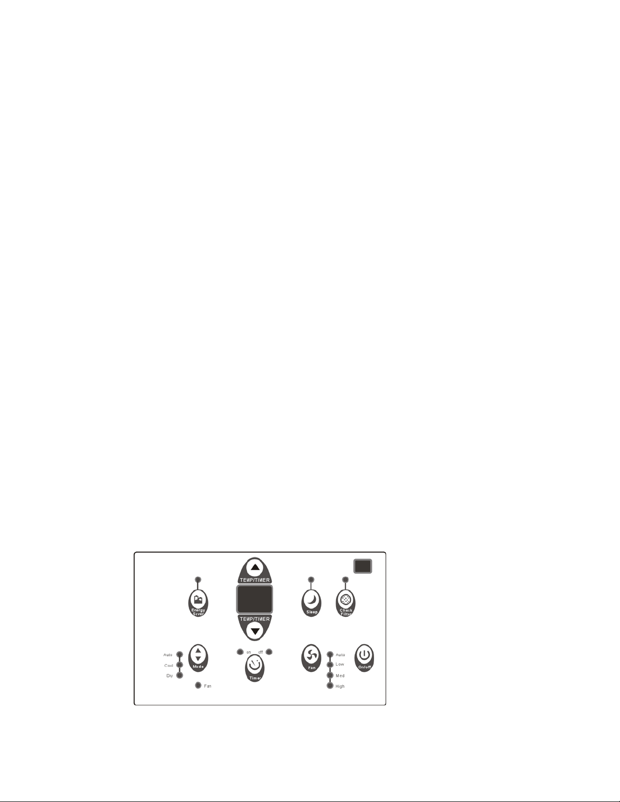
2.2 Control panel illustration
Control panel for cooling only models:
B Panel
Page 5
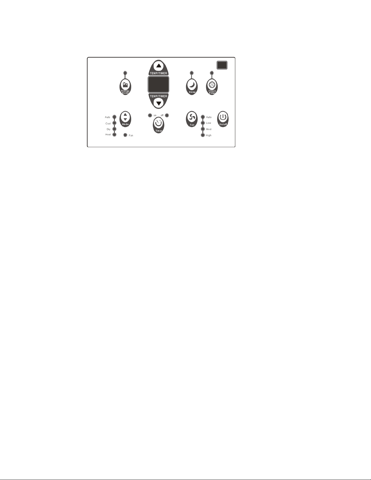
Control panel for cooling and heating models:
Service Manual
Room Air Conditioner with R-410A
Heat Controller, Inc.
4
B Panel
Note: The control panels above are representative of many available models. Your model
may be slightly different.
On/Off (On and Off):
Press this button once to start the unit, press again to stop.
FAN:
Press this button to select appropriate fan speed.
Fan Speed mode has four options - Auto, Low, Med or High. Each time the button is pressed,
the fan speed mode is shifted.
TEMPRATURE UP AND DOWN:
Press the Up(▲)or Down(▼) buttons to change temperature setting.
Press the Up(▲) button to increase the set (operating) temperature of the unit.
Press the Down(▼) button to decrease the set (operating) temperature of the unit.
Press or hold either button until the desired temperature is displayed. This temperature will be
automatically maintained anywhere between 62°F (17°C
) and 86°F (30°C).
MODE:
Pr
ess this button to select operation mode.
Each time you press the button, the operation mode is selected in a sequence that goes from
Auto, Cool, Dry and Fan for cooling only models. and Auto, Cool, Dry, Heat and Fan for electric
heating models.
ENERGY SAVER:
Press this button to activate energy saving. This feature can only function in cooling mode.
SLEEP:
Press this button to save energy and create a more comfortable environment when sleeping. In
this function, the setting temperature will increase by 2° F degrees 30 minutes after the mode is
selected. The temperature will then continue to increase by another 2° F degrees after every 30
minutes. After 7 hours, the unit return to the originally programmed settings. The Sleep mode
program can be cancelled at any time during operation by again pressing the Sleep button.
Page 6

TIMER:
Service Manual
Room Air Conditioner with R-410A
Heat Controller, Inc.
5
Press this button to set the time for unit starting or stopping.
Press or hold the Up (▲) / Down (▼) to set the timer time.
Turning the unit ON or OFF at any time will cancel the Auto Start/Stop function.
CHECK FILTER:
This feature is a reminder to clean the Air Filter for more efficient operation. The “CHECK
FILTER” light will illuminate after 250 hours of operation.
After the filter is cleaned, press this button to confirm that the filter has been cleaned and the
light will go off.
FOLLOW ME (OPTIONAL):
Press the button on the remote controller to activate this feature, which serves as a remote
thermostat allowing for the precise temperature control at its location, rather than using the
thermostat sensor in the unit’s display.
Clean Air (OPTIONAL):
Press this button to start the Clean Air feature, press again to stop.
When this feature is started, the Ionizer is energized to generate abundant anions to fill the
room with refreshing and natural air.
Page 7
Service Manual
Room Air Conditioner with R-410A
Heat Controller, Inc.
6
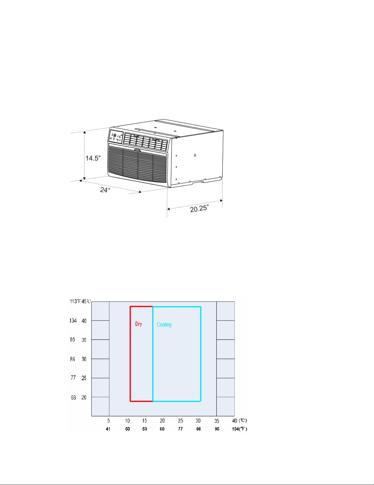
3. UNIT DIMENSION
3.1 Unit dimension:
4. OPERATION LIMITS
4.1 Cooling operation
Outdoor unit air temp DB
Indoor air temp DB
Page 8
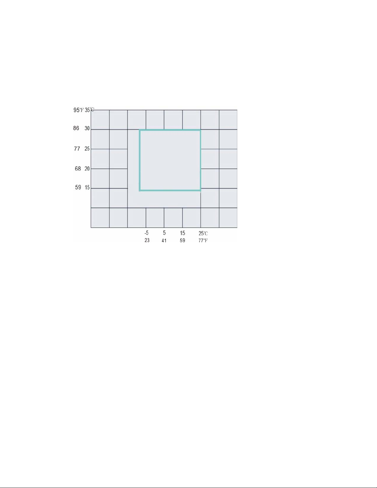
Note: The chart is the result from the continuous operation under constant air
Service Manual
Room Air Conditioner with R-410A
Heat Controller, Inc.
7
temperature conditions. However, the initial pull-down stage is not included.
4.2 Electric heating operation
Indoor air temp DB
Outdoor air temp DB
Note: The chart is the result from the continuous operation under constant air
temperature conditions. However, the initial pull-down stage is not included.
Page 9

5. PROTECTION FUNCTION
Service Manual
Room Air Conditioner with R-410A
Heat Controller, Inc.
8
5.1 Symbol & Meaning
TA: Indoor ambient temperature;
TE: Indoor evaporator temperature;
TS: Setting temperature through the remote controller.
5.2 Protection Function
3 minute compressor time delay
The compressor will wait for 3 minutes before restarting, so as to prevent the pressure
imbalance in refrigerant system from resulting in compressor rotor locking.
Anti-freezing protection in cooling or dry mode
Anti-freezing function is activated according to TE.
If TE is lower than 33.8°F (1℃) for 14 minutes, the evaporator anti-freezing protection will be
activated. The compressor will turn off for 5 minutes. 5 minutes later, if the evaporator pipe
temperature is still lower than 33.8°F (1℃), the compressor remain off; when it gets higher
than 33.8°F (1℃), the compressor will restart and the antifreeze function will be cancelled.
: If the compressor stops operation, the time will be cleared.
Note
If the fan motor turns to High speed or the indoor ambient temperature gets over 78.8°F
(26℃), the time will keep inactive, not be cleared.
Anti-frosting protection and defect at cooling or dry mode
After compressor runs for 3 minutes, if TE is less than 5°F (-15℃) for the subsequent 3
minutes, the anti-frosting protection will be activated and the compressor will stop for the
following 6 minutes. After that time, if the condition for de-frosting function is met again in the
following 10 minutes while the compressor is operating, the unit will display ‘Ed’ to indicate that
the unit is in the defrost mode defect. The compressor and fan motor will turn OFF
Note: The Defect display can be cancelled only by pressing the ON/OFF button on the unit
or the remote controller.
Page 10
Fault Code
Service Manual
Room Air Conditioner with R-410A
Heat Controller, Inc.
9
Defect code Defect explanation
Ed
AS
HS
LO
HI
Evaporator de-frosting defect.
Indoor ambient temperature sensor failure in heating, cooling, dry and auto
mode.
DAHT sensor failure in heating mode.
Sensor disconnection malfunction in fan only mode
Sensor short circuit malfunction in fan only mode
6. COMPONENT OPERATION & TESTING
WARNING:
DISCONNECT THE POWER CORD FROM THE POWER PLUG BEFORE SERVICING OR
TESTING.
6.1 COMPRESSORS
Compressors are single phase, 115 or 230/208 volt, depending on the model number. All
compressor motors are permanent split capacitor type using only a running capacitor across
the start and run terminal.
All compressors are internally spring mounted and externally mounted on rubber isolators.
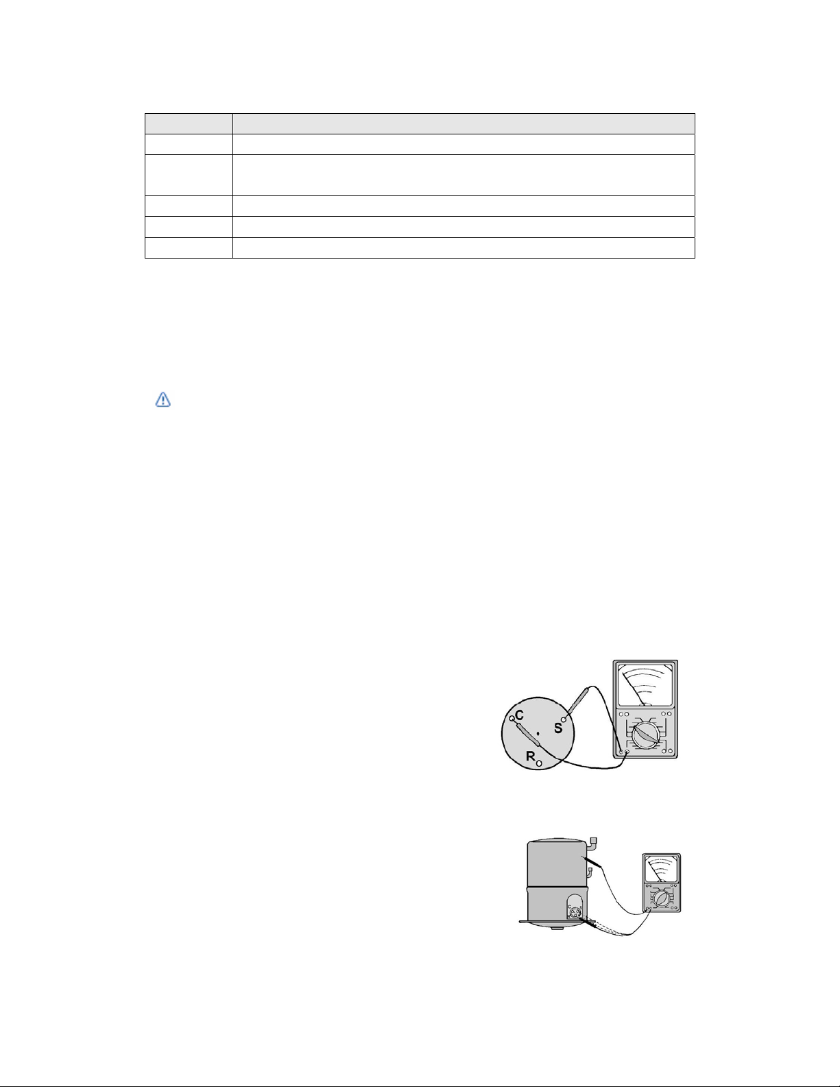
COMPRESSOR WINDING TEST (See Figure 1)
Remove compressor terminal box cover and disconnect
wires from terminals. Using an ohmmeter, check
continuity across the following:
1. Terminal "C" and "S" - no continuity
- open winding - replace compressor.
2. Terminal "C" and "R" - no continuity
- open winding - replace compressor.
3. Terminal "R" and "S" - no continuity
- open winding - replace compressor. Figure 1: Compressor winding test
GROUND TEST
Use an ohmmeter set on its highest scale. Touch
one lead to the compressor body (clean point of
contact as a good connection is a must) and the
other probe in turn to each compressor terminal
(see Figure 2.) If a reading is obtained, the
compressor is grounded and must be replaced. Figure 2: Typical ground test
Page 11
CHECKING COMPRESSOR EFFICIENCY
Service Manual
Room Air Conditioner with R-410A
Heat Controller, Inc.
10
The reason for compressor inefficiency is normally due to broken or damaged suction and/or
discharge valves, reducing the ability of the compressor to pump refrigerant gas.
This condition can be checked as follows:
1. Install a piercing valve on the suction and discharge or liquid process tube.
2. Attach gauges to the high and low sides of the system.
3. Start the system and run a “cooling performance test.”
If test shows:
A. Below normal high side pressure.
B. Above normal low side pressure.
C. Low temperature difference across coil.
The compressor valves are faulty - replace the compressor.
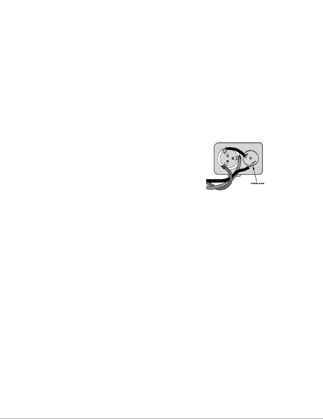
THERMAL OVERLOAD (External)
Some compressors are equipped with an external overload which
is located in the compressor terminal box adjacent to the
compressor body (see Figure 3.) The overload is wired in series
with the common motor terminal. The overload senses both major
amperage and compressor temperature. High motor temperature
or amperage heats the disc causing it to open and break the
circuit to the common motor terminal. Figure 3: External overload
Heat generated within the compressor shell is usually due to:
1. High amperage.
2. Low refrigerant charge.
3. Frequent recycling.
4. Dirty condenser.
TERMINAL OVERLOAD – TEST (Compressor - External Type)
1. Remove overload.
2. Allow time for overload to reset before attempting to test.
3. Apply ohmmeter probes to terminals on overload wires. There should be continuity through
the overload.
TERMINAL OVERLOAD (Internal)
Some model compressors are equipped with an internal overload. The overload is embedded
in the motor windings to sense the winding temperature and/or current draw. The overload is
connected in series with the common motor terminal.
Should the internal temperature and/or current draw become excessive, the contacts in the
overload will open, turning off the compressor. The overload will automatically reset, but may
require several hours before the heat is dissipated.
Page 12

CHECKING THE INTERNAL OVERLOAD (see Figure 4.)
Service Manual
Room Air Conditioner with R-410A
Heat Controller, Inc.
11
1. With no power to unit, remove the leads from the compressor
terminals.
2. Using an ohmmeter, test continuity between terminals C-S
and C-R. If not continuous, the compressor overload is open
and the compressor must be replaced.
Figure 4: Internal overload
6.2 FAN MOTOR
A single phase permanent split capacitor motor is used to drive the evaporator blower and
condenser fan. A self-resetting overload is located inside the motor to protect against high
temperature and high amperage conditions.
FAN MOTOR - TEST
1. Determine that capacitor is serviceable.
2. Disconnect fan motor wires from fan speed switch or system switch.
3. Apply "live" test cord probes on Red wire and common terminal of capacitor. Motor should
run at high speed.
4. Apply "live" test cord probes on Yellow wire and common terminal of capacitor. Motor should
run at mid speed.
5. Apply "live" test cord probes on White wire and common terminal of capacitor. Motor should
run at low speed.
6. Apply "live" test cord probes on each of the remaining wires from the speed switch or
system switch to test intermediate speeds.
6.3 CAPACITOR, RUN
A run capacitor is wired across the auxiliary and main
winding of a single phase permanent split capacitor motor
such as the compressor and fan motor. A single capacitor
can be used for each motor or a dual rated capacitor can
be used for both.
The capacitor's primary function is to reduce the line
current while greatly improving the torque characteristics
of a motor. The capacitor also reduces the line current to
the motor by improving the power factor of the load. The Figure 5: Run capacitor
hook-up line side of the capacitor is marked with a red dot and is
wired to the line side of the circuit (see Figure 5.)
CAPACITOR - TEST
1. Remove capacitor from unit.
2. Check for visual damage such as bulges, cracks, or leaks.
3. For dual rated, apply an ohmmeter lead to common (C) terminal and the other probe to the
Page 13

compressor (HERM) terminal. A satisfactory capacitor will cause a deflection on the pointer,
Service Manual
Room Air Conditioner with R-410A
Heat Controller, Inc.
12
then gradually move back to infinity.
4. Reverse the leads of the probe and momentarily touch the capacitor terminals. The
deflection of the pointer should be two times that of the first check if the capacitor is good.
5. Repeat steps 3 and 4 to check fan motor capacitor.
NOTE: A shorted capacitor will indicate a low resistance and the pointer will move to the "0"
end of the scale and remain there as long as the probes are connected.
An open capacitor will show no movement of the pointer when placed across the
terminals of the capacitor.
6.4 THERMOSTAT ADJUSTMENT
No attempt should be made to adjust thermostat. Due to the sensitivity of the internal
mechanism and the sophisticated equipment required to check the calibration, it is suggested
that the thermostat be replaced rather than calibrated. Thermostat bulb must be straight to
insure proper performance.
6.5 HEATING ELEMENT - See Figure 6
All electric heater models are equipped with a heating element.
The heating element contains a fuse link and a heater limit
switch. The fuse link is in series with the power supply and
will open and interrupt the power when the temperature
reaches 183.2°F (84°C) or 199.4°F (93°C) depending on series
model, or a short circuit occurs in the heating element.
Once the fuse link separates, a new fuse link must
be installed. NOTE: Always replace with the exact replacement.
The heater element has a high limit control. This control is a
bimetal thermostat mounted in the top of the heating element. Figure 6: Heating element
Should the fan motor fail or filter become clogged, the high limit
control will open and interrupt power to the heater before reaching an unsafe temperature
condition.
The control is designed to open at 104°F (40°C). Test continuity below 104°F (40°C). and for
open above 104°F (40°C)..
Press the “Mode” button, select “Heat” mode, to bring on the heating element and turn off the
compressor. The room temperature sensor will then control the cycling of the element when
the selected indoor temperature is reached.
Testing of the elements can be done using an ohmmeter across the terminals after the
connecting wires have been removed. A cold resistance reading of approximately 10.2 ohms
for the 4.7 KW heater should be registered.
Page 14

6.6 VALVE, DRAIN PAN (see Figure 7)
Service Manual
Room Air Conditioner with R-410A
Heat Controller, Inc.
13
During the cooling mode of operation, condensate which
collects in the drain pan is picked up by the condenser
fan blade and sprayed onto the condenser coil. This
assists in cooling the refrigerant plus evaporating the
water.
During the heating mode of operation, it is necessary
that water be removed to prevent it from freezing due to
cold outside temperatures. This could cause the
condenser fan blade to freeze in the accumulated water
and prevent it from turning.
To provide a means of draining this water, a bellows type Figure 7: Drain pan valve
drain valve is installed over a drain opening in the Chassis.
This valve is temperature sensitive and will open when the outside temperature reaches 40°F
(4.4°C). The valve will close gradually as the temperature rises above 40°F (4.4°C) to fully
close at 68°F (20°C).
6.7 SEALED REFRIGERATION SYSTEM REPAIRS
EQUIPMENT REQUIRED:
1. Voltmeter
2. Ammeter
3. Ohmmeter
4. E.P.A. Approved Refrigerant Recovery System.
5. Vacuum Pump (capable of 200 microns or less vacuum.)
6. Acetylene Welder
7. Electronic Halogen Leak Detector (G.E. Type H-6 or equivalent.)
8. Accurate refrigerant charge measuring device such as:
a. Balance Scales - 1/2 oz. accuracy
b. Charging Board - 1/2 oz. accuracy
9. High Pressure Gauge - (0 - 400 lbs.)
10. Low Pressure Gauge - (30 - 150 lbs.)
11. Vacuum Gauge - (0 - 1000 microns)
EQUIPMENT MUST BE CAPABLE OF:
1. Recovery CFC's as low as 5%.
2. Evacuation from both the high side and low side of the system simultaneously.
3. Introducing refrigerant charge into high side of the system.
4. Accurately weighing the refrigerant charge actually introduced into the system.
5. Facilities for flowing nitrogen through refrigeration tubing during all brazing processes.
Page 15

HERMETIC COMPONENT REPLACEMENT
Service Manual
Room Air Conditioner with R-410A
Heat Controller, Inc.
14
The following procedure applies when replacing components in the sealed refrigeration circuit
or repairing refrigerant leaks. (Compressor, condenser, evaporator, capillary tube, refrigerant
leaks, etc.)
1. Recover the refrigerant from the system at the process tube located on the high side of the
system by installing a line tap on the process tube. Apply gauge from process tube to EPA
approved gauges from process tube to EPA approved recovery system. Recover CFCs in
system to at least 5%.
2. Cut the process tube below pinch off on the suction side of the compressor.
3. Connect the line from the nitrogen tank to the suction process tube.
4. Drift dry nitrogen through the system and unsolder the more distant connection first. (Filter
drier, high side process tube, etc.)
5. Replace inoperative component, and always install a new filter drier. Drift dry nitrogen
through the system when making these connections.
6. Pressurize system to 30 PSIG with proper refrigerant and boost refrigerant pressure to 150
PSIG with dry nitrogen.
7. Leak test complete system with electric halogen leak detector, correcting any leaks found.
8. Reduce the system to zero gauge pressure.
9. Connect vacuum pump to high side and low side of system with deep vacuum hoses, or
copper tubing. (Do not use regular hoses.)
10. Evacuate system to maximum absolute holding pressure of 200 microns or less.
NOTE: This process can be sped up by use of heat lamps, or by breaking the vacuum with
refrigerant or dry nitrogen at 5,000 microns. Pressurize system to 5 PSIG and
leave a minimum of 10 minutes. Recover refrigerant, and proceed with evacuation
of a pressure of 200 microns or a minimum of 10%.
11. Break vacuum by charging system from the high side with the correct amount of refrigerant
specified. This will prevent boiling the oil out of the crankcase.
NOTE: If the entire charge will not enter the high side, allow the remainder to enter the low
Page 16

side in small increments while operating the unit.
Service Manual
Room Air Conditioner with R-410A
Heat Controller, Inc.
15
12. Restart unit several times after allowing pressures to stabilize. Pinch off process tubes, cut
and solder the ends. Remove pinch off tool, and leak check the process tube ends.
SPECIAL PROCEDURE IN THE CASE OF COMPRESSOR MOTOR BURNOUT
1. Recover all refrigerant and oil from the system.
2. Remove compressor, capillary tube and filter drier from the system.
3. Flush evaporator condenser and all connecting tubing with dry nitrogen or equivalent, to
remove all contamination from system. Inspect suction and discharge line for carbon
deposits. Remove and clean if necessary.
4. Reassemble the system, including new drier strainer and capillary tube.
5. Proceed with process as outlined under hermetic component replacement.
ROTARY COMPRESSOR SPECIAL TROUBLESHOOTING AND SERVICE
Basically, troubleshooting and servicing rotary compressors is the same as on the
reciprocating compressor with only a few exceptions.
1. Because of the spinning motion of the rotary, the mounts are critical. If vibration is present,
check the mounts carefully..
2. The electrical terminals on the rotary are in a different order than the reciprocating
compressors. The terminal markings are on the cover gasket. Use your wiring diagram to
insure correct connections.
REFRIGERANT CHARGE
1. The refrigerant charge is extremely critical. Measure charge carefully - as exact as possible
to the nameplate charge.
2. The correct method for charging the a rotary compressor is to introduce liquid refrigerant
into the high side of the system with the unit off. Then start compressor and enter the
balance of the charge, gas only, into the low side.
The introduction of liquid into the low side, without the use of a capillary tube, will cause
damage to the discharge valve of the rotary compressor.
Page 17

Service Manual
Room Air Conditioner with R-410A
Heat Controller, Inc.
16
7. WIRING DIAGRAM
The wiring diagrams listed below are representative of models deployed with full features. Your
model may not offer all these features, accordingly it will slightly differ from your wiring diagram
in these optional features area. Refer to the actual wiring diagram included wit your unit.
Wiring Diagram For TTW Cooling only models:
Wiring Diagram For TTW Cooling and Heating models:
Page 18

8. TROUBLESHOOTING
Service Manual
Room Air Conditioner with R-410A
Heat Controller, Inc.
17
In general, problems are classified by three types. One is called Starting Failure which is
caused from an electrical defect, another is ineffective Air Conditioning caused by a defect in
the refrigeration circuit and improper application, and the other is called Structure Damage.
8.1 Flow Chart
Display keeps showing "AS" or "HS".
Check the wiring.
No
Check the resistance of room temperature sensor,
according to the characteristic table.
No
Replace the main control board.
Display keeps showing "LO" or "HI".
Check whether the room ambient temperature is over 31C (90F) or lower than 16C (60F).
No
Check the resistance of room temperature sensor,
according to the characteristic table.
No
Replace the control board.
Ye s
Correct or repair the wires.
Ye s
Ye s
Replace the room temperature sensor.
Replace the room temperature sensor.
Page 19

(op
Service Manual
Room Air Conditioner with R-410A
Heat Controller, Inc.
18
The "filter check" lamp is on.
Press "filter check" button several times and check whether the problem stops.
No
Replace the main control board.
Button of remote controller doesn’t work.
Check the power supply.
No
Check whether the voltage of battery is lower than 2.2V.
Ye s
Replace with new batteries.
No
Check whether the failure button is locked by button holder.
No
Check whether the buttons on the unit work normally.
Ye s
Replace the remote controller.
No
Check the wiring.
No
Check whether the transformer damaged
en circuit or short circuit).
No
Ye s
Replace the transformer.
Check whether other modes work normally.
No
Replace the display board.
No
Replace the main control board.
Page 20

Service Manual
Room Air Conditioner with R-410A
Heat Controller, Inc.
19
Operation panel doesn’t work.
Check the power supply.
No
Press the "LED" button of remote controller several times and
check whether the problem stops.
No
Check the wiring of display board.
Ye s
Repair the wiring.
No
Replace the display board.
No
Replace the main control board.
Follow me mode doesn’t work.
Check the power supply.
No
Press "follow me" button several times and check whether this mode can work.
(Pay attention to the position of Remote controller)
No
Check w hether other functions of r emote
work or not.
No
Replace the remote controller.
Ye s
Check the batteries. Replace it if failed.
No
Replace the display board.
No
Replace the main control board.
Page 21

Service Manual
Room Air Conditioner with R-410A
Heat Controller, Inc.
20
Display keeps showing "Ed".
Check whether the evaporator frosts.
No
Check whether the indoor air inlet is blocked.
No
Check whether the indoor ambient temperature is too low.
No
Check whether the indoor dust filter is too dirty.
No
Check whether there is too much water on the chassis.
No
Check the wiring of pipe temperature sensor.
No
Check the pipe temperature sensor. Replace the pipe temperature sensor.
Replace the main control board.
Page 22

Service Manual
Room Air Conditioner with R-410A
Heat Controller, Inc.
21
Compressor doesn’t work.
Check whether the indoor temperature is lower than 59F (15°C).
No
Check the power supply.
No
Check whether the voltage is too high or too low.
No
Check the wiring.
No
Check whether the compressor is in overload protection mode.
No
Check whether the relay of compressor in PCB works normally (Start the uni t, wait 3 m inutes
for the compressor to turn on, and set the unit in the cool mode and 26F (17C). Then check the
output of relay and replace the PCB if failed.
No
Check whether the external
protector works normally.
Remove t he overl oad p rotector a nd cool t o
normal temperature. Then che ck whether it is
open circuit. Replace if failed.
Comparing with compressor specification, check the resistance of compressor.
No
Replace the compressor.
Page 23

Service Manual
Room Air Conditioner with R-410A
Heat Controller, Inc.
22
The fan motor doesn’t work.
Check the power supply.
Check whether the indoor (outdoor) fan is locked.
No
Check the wiring.
No
Check whether the relays on PCB for motor work normally.
No
Comparing w ith f an m otor spec ification, check
the resistance of fan motor.
No
Cooling mode doesn’t work or not cooling not enough.
Check the operation mode.
Check the set temperature.
Check whether the filter is dirty/clogged.
No
Start t he unit in t he cool m ode and check w hether the
temperature of compressor’s discharge pipe is between 176°F
(80℃) to 194°F (90℃). If no, recharge refrigerant.
Replace the capillary tube.
Replace the fan motor.
Page 24

Service Manual
Room Air Conditioner with R-410A
Heat Controller, Inc.
23
The air conditioner doesn’t work.
Check the power supply.
No
Check the wiring.
No
Check whether the transformer has failed. Measure the output voltage of transformer and
check whether it is the range from +5V to 12V. If not, replace the transformer.
No
Replace the PCB.
The compressor doesn’t stop, after the set temperature is reached.
Check the wiring.
No
Check whether the unit can turn off using the remote controller.
No
Check whether all te mperature sensors a re n ormal, comparing
with the resistance table. If not, replace the sensor.
No
Replace the PCB.
Page 25

Service Manual
Room Air Conditioner with R-410A
Heat Controller, Inc.
24
The compressor cycles on/off frequently.
Check whether the airflow is blocked.
No
Check if the fan motor isn’t working.
No
Check whether capacitor of compressor is working normally.
No
Check whether the relay of compressor on PCB works normally.
No
Replace the PCB.
No
Check whether the capillary tube is blocked.
No
Replace the capillary.
No
Replace the compressor.
Temperature controller doesn’t work or is unstable.
Check whether the set temperature is reached.
No
Test the several higher temperature set points and check whether unit works normally.
No
Check the wiring.
No
Check whether the unit is correctly installed.
No
Check the temperature controller. Replace if failed.
Page 26

Service Manual
Room Air Conditioner with R-410A
Heat Controller, Inc.
25
Water drips from the unit.
Check whether the ambient humidity is too high.
No
Check whether the indoor outlet airflow foam is wet if water is dripping from the louvers.
No
Check whether the unit is correctly installed.
No
Check whether the air outlet foam is installed normally.
No
Check whether the foam of evaporator base is damaged.
No
Check whether the drain passage of evaporator is blocked. Replace if failed.
Temperature controller interrupts frequently.
Check whether the set temperature is reached.
No
Check the wiring.
No
Check whether the compressor is in the protection mode or 3 minute time delay.
No
Check the specification of temperature controller. Replace if failed
Page 27

Service Manual
Room Air Conditioner with R-410A
Heat Controller, Inc.
26
Not heating or not heating enough. (Cooling and Electric Heater)
Check the mode.
No
Check whether the airflow speed is too low.
No
Check the heat load of the room.
No
Check the specification of PTC-heater.
Fan motor speed can’t change. (Electric Control)
Check the wiring.
No
Check the capacitor of fan motor. Replace if failed.
No
Replace the PCB.
No
Check the resistance of fan motorand replace the motor if failed.
Fan motor speed can’t change. (Mechanical Control)
Check whether the selector is damaged.
No
Check whether the ca pacitor of fan motor is in the rang e from 95 % to
105% of rated capacity. Replace the capacitor if failed.
No
Check the resistance of fan motor and replace if failed.
Page 28

Service Manual
Room Air Conditioner with R-410A
Heat Controller, Inc.
27
8.2 General Troubleshooting
PROBLEM P OSSIBLE CAUSE REMARK
Check voltage at electrical outlet. Correct if
none.
Check voltage at the power cord terminal.
Replace the power cord if none.
Connect wire. Refer to wiring diagram for
terminal identification. Repair or replace
loose terminal.
Test capacitor. Replace if not within +/-10%
of manufacturer's rating. Replace if
shorted, open or damaged.
Fan blade hitting shroud or blower hitting
scroll. Realign assembly. Check fan motor
bearings. Replace the motor if motor shaft
do not rotate.
Check voltage. Call an electrician if not
within limits.
Test capacitor. Replace if not within +/-10%
of manufacturer's rating.
Check bearings. Replace the motor if the
fan blade cannot rotate freely.
Pay attention to any change from high
speed to low speed. Replace the motor if
the speed does not change.
Replace the fan if cracked, out of balance,
or partially missing.
Replace the blower if cracked, out of
balance, or partially missing.
Fan motor doesn’t
run.
Fan motor runs
intermittently
Fan motor noise.
No power
Power supply cord
Wire disconnected or
connection loose
Main switch failure Check and replace the main switch if failure.
Capacitor (Discharge
capacitor before testing)
Will not rotate
Cycles on overload.
Fan
Blower
Loose screws Tighten them.
Compressor does
not to stop although
room temperature
has reached set
temperature.
Replace the motor if knocking sounds continue
Worn bearings
when running or loose, or the motor hums or
noise appears to be internal while running.
Thermostat Check and replace the thermostat.
Page 29

PROBLEM P OSSIBLE CAUSE REMARK
Service Manual
Room Air Conditioner with R-410A
Heat Controller, Inc.
28
Air filter Clean or replace if restricted.
Vent door Close if open.
Unit undersized
Determine if the unit is properly sized for
the area to be cooled or heated.
Condenser and Evaporator Clean if restricted.
Fan motor
Room structure
Check the fan capacitor and replace if not
within +/-10% of manufacturer’s rating.
Take proper measures to make sure doors
and windows are sealed well.
Clean or remove if any barrier is found to
Air flow
block the inlet/outlet wind flow of the unit
(drapes, shrubs, etc.).
Add a awning if the unit is exposed to direct
Sunlight
sunlight or move the unit to another window
that’s not exposed to direct sunlight.
Check the tubes for leakage. Reclaim the
Insufficient cooling
or heating.
Refrigerant loss
refrigerant, correct the leakage points and
recharge.
Regulate the flow of capillary tube and
Capillary tube
ensure the evaporating temperature is
appropriate, if the evaporator is frosted.
Replace if blocked. Repair joint if leaking.
The inlet and outlet valve of the
compressor may be damaged, making the
low pressure connected with the high
Compressor
pressure. The refrigerating system can not
produce high pressure and low pressure.
Replace the compressor after checking for
the reason of failure.
Heat sources
Reduce if too many (dryers, electric
heaters, small appliances, etc.)
If drainage is blocked it will increase the
Drainage
efficiency in cooling mode, but will cause
the condenser to frost in heating mode.
Remove any obstacles.
If the amount of the refrigerant is too large,
making the compressor load too large.
Reclaim and recharge the refrigerant after
checking for the reason of failure.
The compressor is seized. Replace after
checking for the reason of failure.
Stop instantly after
startup.
Refrigerant
Compressor
Page 30

PROBLEM P OSSIBLE CAUSE REMARK
Service Manual
Room Air Conditioner with R-410A
Heat Controller, Inc.
29
Check the voltage. Call an electrician if not
No power
within correct limits of +/- 10% of nominal
voltage rating required.
Wiring Check terminals. Repair and correct if loose.
No cooling or
heating.
Temperature setting Check and adjust the thermostat.
Main switch setting Check and adjust the main switch setting.
Reversing valve wire
Check the resistance of reversing valve wire.
Replace the wire if short, open or damaged.
If the reversing valve is blocked, the heating
Reversing valve
mode will not operate. Replace the reversing
valve after checking the reason for failure.
Check voltage. Call Supply Authority if not
Voltage
within limits of +/- 10% of nominal voltage
rating required.
Check the wire connections, if loose, repair
or replace the terminal. If wires are off,
Wiring
refer to wiring diagram for identification,
and replace. Check wire locations. If not
per wiring diagram, correct.
Compressor will not
run while fan motor
runs.
Main switch failure Check and replace the main switch if failed.
Check the capacitor.
Capacitor (Discharge
capacitor before testing)
Replace if not within +/-10% of
manufacturer’s rating. Replace if shorted,
open, or damaged.
Check the thermostat setting if not at the
Thermostat
coolest (in cooling mode) or the warmest (in
heating mode). Try adjusting these settings.
Check the compressor for open circuit or
Compressor
ground. If open or grounded, replace the
compressor.
If copper tubing is rubbing against the cabinet
Excessive noise. Copper tubing
and vibrating while operating, remove the
cabinet and carefully rearrange tubing to not
contact cabinet, compressor, shroud and barrier.
The input power supply voltage is too low or
Power supply
The unit starts and
stops frequently.
Outdoor temperature
not within +/- 10% of nominal voltage rating
required. Call an electrician if not within limits.
When the outdoor temperature is too high,
the compressor will go into a protection
mode or 3 minute time delay.
Page 31

8.3 Troubleshooting Cooling
Service Manual
Room Air Conditioner with R-410A
Heat Controller, Inc.
30
PROBLEM POSSIBLE CAUSE TO CORRECT
Compressor
does not run.
Fan motor
does not run.
Does not
cool, or cools
only slightly.
Low voltage. Check for voltage at compressor. 115 volt
Thermostat not set cold enough
or inoperative.
Compressor hums but cuts off on
overload.
Open or shorted compressor
windings.
Open overload. Test overload protector and replace if
Open capacitor. Test for continuity in all positions.
Inoperative system switch. Replace if inoperative.
Broken, loose or incorrect wiring. Refer to appropriate wiring diagram to check
Inoperative system switch. Test switch and replace in inoperative.
Broken, loose or incorrect wiring. Refer to applicable wiring diagram.
Open capacitor. Test capacitor and replace if inoperative.
Fan speed switch open. Test switch and replace if inoperative.
Inoperative fan motor.
Undersized unit. Refer to Sizing Charts.
Thermostat open or inoperative. Set to coldest position. Test thermostat and
Dirty filter. Clean as recommended in Owner’s Manual.
Dirty or plugged condenser or
evaporator coil.
Poor air circulation in area being
cooled.
Fresh air or exhaust air door
open on applicable models.
Low capacity – undercharge. Check for leak and make repair.
Compressor not pumping
properly.
and 230 volt units will operate at 10%
voltage variance
Set thermostat to coldest position. Test
thermostat and replace if inoperative.
Hard start compressor. Direct test
compressor. If compressor starts, add
starting components.
Check for continuity and resistance.
inoperative.
Test capacitor and replace if inoperative.
wiring.
Test fan motor and replace if inoperative.
(Be sure internal overload has had time to
reset.)
replace if necessary.
Use steam or detergents to clean.
Adjust discharge air louvers. Use high fan
speed.
Close doors. Instruct customer on use of this
feature.
Check amperage draw against nameplate. If
not conclusive, make pressure test.
Page 32

Service Manual
Room Air Conditioner with R-410A
Heat Controller, Inc.
31
PROBLEM POSSIBLE CAUSE TO CORRECT
Unit does
not run.
Thermostat
does not
turn unit off.
Evaporator
coil freezes
up.
Compressor
runs
continually,
does not
cycle off.
Fuse blown or circuit tripped. Replace fuse, reset breaker. If repeats,
check fuse or breaker size. Check for shorts
in unit wiring and components.
Power cord not plugged in. Set switch correctly.
System switch in "Off" position. Test for continuity in each switch position.
Inoperative system switch. Check wiring and connections.
Loose or disconnected wiring at
Reconnect per wiring diagram.
switch or other components.
Thermostat contacts stuck. Replace thermostat.
Thermostat set at coldest point. Turn to higher temperature setting to see if
the unit cycles off.
Incorrect wiring. Refer to appropriate wiring diagram.
Unit undersized for area to be
Refer to Sizing Chart.
cooled.
Dirty filter. Clean as recommended in Owner’s Manual.
Restricted air flow. Check for dirty or obstructed coil - clean as
required or remove obsticales.
Inoperative thermostat. Test for shorted thermostat or stuck
contacts.
Short of refrigerant. De-ice coil and check for leak.
Inoperative fan motor. Test fan motor and replace if inoperative.
Partially restricted capillary. De-ice coil. Check temperature differential
across coil. Touch test coil return bends for
same temperature. Test for low running
current.
Excessive heat load. Unit undersized. Test cooling performance
of unit. Replace with larger unit.
Restriction in line. Check for partially iced coil. Check
temperature split across coil.
Refrigerant leak. Check for oil at silver soldered connections.
Check for partially iced coil. Check split across
coil. Check for low running amperage.
Thermostat contacts stuck Check operation of thermostat. Replace if
contacts remain closed.
Thermostat incorrectly wired. Refer to appropriate wiring diagram.
Page 33

PROBLEM POSSIBLE CAUSE TO CORRECT
Service Manual
Room Air Conditioner with R-410A
Heat Controller, Inc.
32
Compressor
attempts to
start, or runs
for short
periods only.
Cycles on
overload.
soon.
Compressor attempts to start
before system pressures are
equalized.
Low or fluctuating voltage. Check voltage with unit operating. Check for
Check operation of unit. Replace overload if Overload inoperative. Opens too
system operation is satisfactory.
Allow a minimum of 2 minutes for pressures
to equalize before attempting to restart.
other appliances on circuit. Air conditioner
should be on separate circuit for proper
voltage, and be fused separately.
8.4 Troubleshooting Heating (Cooling/Electric Heater Models)
PROBLEM P OSSIBLE CAUSE TO CORRECT
Fan
Operates –
heating
element does
not come on.
Heating
inadequate.
Fan operates
in "Constant"
speed, but
not in "Auto"
Long "off"
and "on"
cycles.
Heater relay or contactor coil open. Check continuity of coil. Inspect, test
continuity with ohmmeter.
Heater relay or contactor stuck
open, pitted or burned.
High limit control open. Check continuity. Check reason for failure.
Open thermal fuse. Check voltage across heater terminals.
Open or shorted element. Check amperage draw of heater.
Loose connections. Tighten all terminals.
Restricted filter. Clean as recommended in Owner’s Manual.
Cycling high limit control. Control is set to open at 155°F± 5°F (68.3°C
Exhaust or fresh air door open. Check position of fresh air door control slide.
Fan relay contacts open. Check continuity of fan relay.
Inoperative system switch. Check connections on system switch and
Loose connection. Check connections on system switch and
Heat anticipator (resistor)
shorted.
Defective temperature sensor. Replace temp. sensor and check operation.
Check continuity – if open, replace.
+/- 15°C) and close at 130°F± 8°F (54.4°C +/-
13°C). If cycling prematurely, replace control.
Adjust cable if door does not close properly.
NOTE: Some models have fan relay energized
during heating cycle while others do not.
fan relay.
fan relay.
Disconnect power to unit. Remove resistor
from thermostat bulb block. Plug in unit and
allow to operate. Feel resistor for heat. If no
heat is felt, replace resistor.
Page 34

Service Manual
Room Air Conditioner with R-410A
Heat Controller, Inc.
33
PROBLEM POSSIBLE CAUSE TO CORRECT
Fan motor
does not
operate in
"Constant"
speed or
"Auto” speed.
Unit does not
heat.
Defective motor. Check and replace.
Open or shorted capacitor. Replace capacitor and check.
Condenser fan frozen to Chassis. Check if drain pan valve is open. If not,
replace.
Loose connections. Check all connections. Check voltage to fan
motor.
Fuse link. Check fuse link for continuity. If defective,
replace.
Heating element shorted. Check amperage draw of element. If no
amperage, replace.
Incorrect wiring. Check voltage to element. If voltage is okay,
check wiring.
Heat relay or heater contactor coil
Defective coil. Test coil for continuity.
open.
Page 35

9. INSTALLATION ACCESSORY LIST
Service Manual
Room Air Conditioner with R-410A
Heat Controller, Inc.
34
▌ Part list for CD Series:
No. Part No. Part Name Quantity
1 202921890000 Grille(Aluminum) 1
2 201121890009 Grille(plastic) 1
3 201121890006 Stuffer seal 1
4 201121890007 Trim Frame(side legs) 2
5 201121890008 Trim Frame(top & bottom legs) 2
10. CHARACTERISTIC OF TEMPERATURE SENSOR
Temp.°F (°C) Resistance KΩ Temp.°F (°C) Resistance KΩ Temp.°F (°C) Resistance KΩ
14 (-10) 62.2756 62.6 (17) 14.6181 111.2 (44) 4.3874
16 (-9) 58.7079 64.4 (18) 13.918 113 (45) 4.2126
18 (-8) 56.3694 66.3 (19) 13.2631 114.8 (46) 4.0459
194. (-7) 52.2438 68 (20) 12.6431 116.6 (47) 3.8867
21.2 (-6) 49.3161 69.8 (21) 12.0561 118.4 (48) 3.7348
23 (-5) 46.5725 71.6 (22) 11.5000 120.2 (49) 3.5896
25 (-4) 44.0000 73.4 (23) 10.9731 122 (50) 3.4510
26.6 (-3) 41.5878 75.2 (24) 10.4736 123.8 (51) 3.3185
28.4 (-2) 39.8239 77 (25) 10.0000 125.6 (52) 3.1918
30.2 (-1) 37.1988 78.8 (26) 9.5507 127.4 (53) 3.0707
32 (0) 35.2024 80.6 (27) 9.1245 129.2 (54) 2.959
33.8 (1) 33.3269 82.4 (28) 8.7198 131 (55) 2.8442
35.6 (2) 31.5635 84.2 (29) 8.3357 132.8 (56) 2.7382
37.4 (3) 29.9058 86 (30) 7.9708 134.6 (57) 2.6368
39.2 (4) 28.3459 87.8 (31) 7.6241 136.4 (58) 2.5397
41 (5) 26.8778 89.6 (32) 7.2946 138.2 (59) 2.4468
42.8 (6) 25.4954 91.4 (33) 6.9814 140 (60) 2.3577
44.6 (7) 24.1932 93.2 (34) 6.6835 141.8 (61) 2.2725
46.4 (8) 22.5662 95 (35) 6.4002 143.6 (62) 2.1907
48.2 (9) 21.8094 96.8 (36) 6.1306 145.4 (63) 2.1124
50 (10) 20.7184 98.6 (37) 5.8736 147.2 (64) 2.0373
51.8 (11) 19.6891 100.4 (38) 5.6296 149 (65) 1.9653
53.6 (12) 18.7177 102.2 (39) 5.3969 150.8 (66) 1.8963
55.4 (13) 17.8005 104 (40) 5.1752 152.6 (67) 1.830
57.2 (14) 16.9341 105.8 (41) 4.9639 154.4 (68) 1.7665
57 (15) 16.1156 107.6 (42) 4.7625 156.2 (69) 1.7055
60.8 (16) 15.3418 109.4 (43) 4.5705 158 (70) 1.6469
Page 36

03/2010
 Loading...