

Heartland 2612 User Instructions

Installation
Operation
and
Maintenance
Instructions
Woodburning Cookstove
Model
2612 Blackwood
CONTENTS
Safety Instructions ..............................................................3
Warranty Registration ........................................................4
Unpacking ...........................................................................5
Installation Instructions ........................................................6
Shelf Installation ..............................................................6
Cooking surface lift handle installation ............................7
Installation ...........................................................................7
Clearances .......................................................................7
Rough in Diagram for Blackwood ....................................8
Chart of Clearances .........................................................9
Clearance Reductions ....................................................10
Floor protection ..............................................................10
Chimneys and Draft ...........................................................10
Recommended Chimney Clearances .............................11
Chimney Connection Requirements ...............................11
Chimney Connector Systems .........................................12
Optioinal Accessories .......................................................13
Heat Shield Kit ................................................................13
Fresh Air kit .....................................................................13
Water Jacket ...................................................................14
Understanding Combustion .............................................15
Woodburning ..................................................................15
Getting Acquainted .........................................................15
Starting the Stove ..........................................................16
Break in Fire .................................................................17
Your First Fire ................................................................17
Summer Burning ...........................................................18
Coal Burning .....................................................................19
Blackwood Coal Grate ...................................................19
Fire Door Damper ..........................................................19
Starting Up a Coal Fire ..................................................19
Recharging a Fire ...........................................................20
Disposal of Ashes (Wood and Coal) ...............................20
Using the Oven and Cooking Surface .............................21
Stove Top Cooking .........................................................21
Oven Cooking ................................................................22
Troubleshooting .................................................................23
Chimneys and Draft .......................................................23
How Chimneys Work .....................................................23
Factors that Affect Draft ................................................23
Checking an Existing Chimney ......................................23
Safety Practices .............................................................24
Flue Pipes ......................................................................24
Maintenance ......................................................................25
Oven Flue passage .........................................................25
Flue Boot Inspection .......................................................26
Oven Damper ..................................................................26
Maintenance Continued ........................................................
Chimney Maintenance ...................................................26
Cooking Surface .............................................................26
Door Gaskets ..................................................................27
Firebox ...........................................................................27
Terms of Reference and Function ....................................28
Overring Caution .............................................................29
Obtaining Service ...............................................................30
Warranty ............................................................................31
CONTACT LOCAL BUILDING OR FIRE OFFICIALS BEFORE INSTALLATION ABOUT
RESTRICTIONS AND INSTALLATION INSPECTION REQUIREMENTS IN YOUR AREA AND
THE NEED FOR OBTAINING A PERMIT.
!
CAUTION
DO NOT USE CHEMICALS OR FLUIDS TO START THE
FIRE. DO NOT BURN GARBAGE OR FLAMMABLE
FLUIDS
!
CAUTION
Read this entire manual before you install and use your
new room heater. If this room heater is not properly in-
stalled, a house re may result. To reduce the risk of re,
follow the installation instructions. Failure to follow instruc-
tions may result in property damage, bodily injury, or even
death.
The Blackwood cookstove is listed to
CSA Standard B366.2MULC Standard
S-627 & UL 1482 by Warnock Hersey
Professional Services Ltd.
is committed to building a quality product
in an environmentally friendly manner. Our processes are
tightly controlled and closely monitored. We have achieved
certications in ISO 9001 for quality assurance, ISO 14001
for environmental management, and OHSAS 18001 for oc-
cupational health and safety from Lloyd’s Register Quality
Assurance.
2
SAFETY INSTRUCTIONS
Important Safety Instructions
Warnings and safety instructions appearing in this guide
are not meant to cover all possible conditions and situa-
tions that may occur. Common sense, caution, and care
must be exercised when installing, maintaining, or operat-
ing this appliance.
Recognize Safety Symbols,
Words, and Labels.
!
WARNING
WARNING-Hazards or unsafe practices with
high probability of personal injury or property / product damage.
!
WARNING
DO NOT STORE OR USE GASOLINE
OR OTHER FLAMMABLE VAPORS
OR LIQUIDS IN THE VICINITY OF
THIS STOVE.
Stove Location - If the range must be located near a
window, avoid using long curtains which could blow
over the stove top, causing a re hazard.
Any openings in the wall behind the stove or in the
oor under the range must be sealed.
Do not set unopened glass or metal containers in the
oven, on the warming shelf, or on the cooking surface.
!
CAUTION
CAUTION-Hazards or unsafe practices which could
result in personal injury or property or product damage.
NOTE
NOTE-Important information to help assure a problem
free installation and operation.
Grease accumulation is the cause of many cooking
res. Clean the oven compartment regularly.
Do not attempt to extinguish a grease re with water.
Cover grease res with a pot lid or baking soda.
Avoid the use of aerosol containers near the range.
Never place pans, cookie sheets or roasters directly
on the oven bottom but use the oven rack in its lowest
position.
3
WARRANTY REGISTRATION
Warranty Registration
It is important you send in your warranty registration card
immediately after taking delivery of your woodburning cookstove.
The following information will be required when registering
your unit.
Serial Number
Date of Manufacture
Date of Purchase
Dealer’s name and address
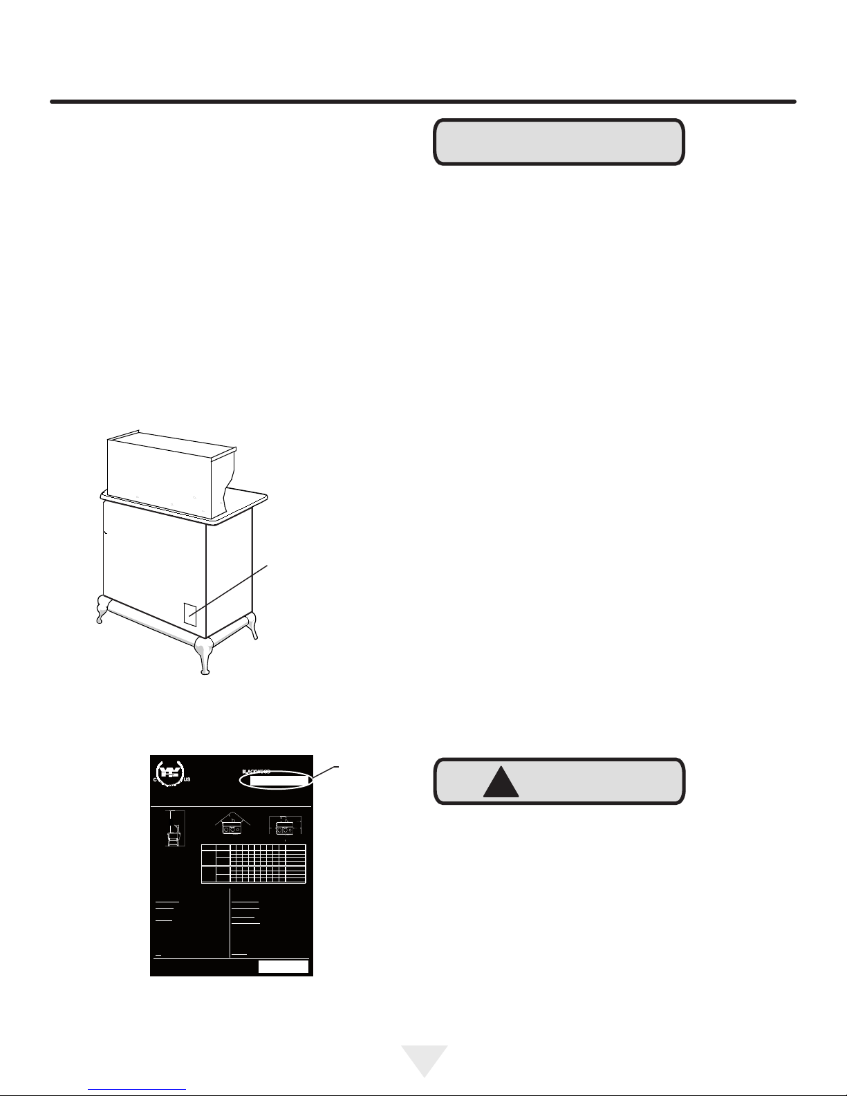
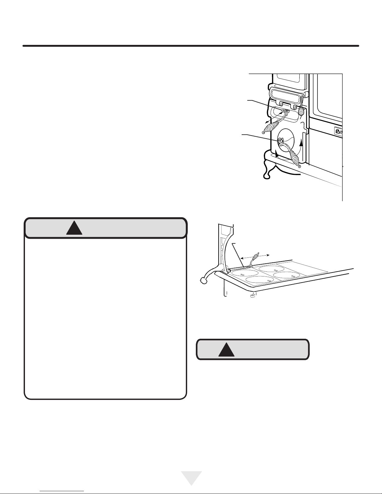
The serial number and date of manufacture can be found
on the serial plate located on the back of the stove. See
Figure 1 and 2.
NOTE
Please read these instructions thoroughly before attempting
to install this stove.
Your woodburning cookstove is a time proven design of
North American heritage. Our cookstoves were rst made
in 1906 and many originals are still in use today. With proper operation and maintenance, your woodburning cookstove will give your family generations of warmth, delightful
meals and untold pleasures.
Take the opportunity to read this manual thoroughly to be-
come familiar with all the installation, operation and maintenance procedures for your stove. You will nd it offers valu-
able insight into how a cookstove functions.
Save These Instructions
Keep the manual available for future reference. The manual
is an important part of your stove. If your stove is sold, de-
liver the manual to the new owner along with the stove.
-Serial plate,
see Figure 2
Figure 1
R
T
E
E
T
K
N
I
LISTED SOLID FUEL BURNING COOKSTOVES
POELE A AIR RADIANT
MODELS/MODELES -
TESTED TO: / MIS A L'EPREUVE SELON:
Contact local building officials about restrictions and installation inspection in your area.
Renseignez-vous aupres des autorites locales de la construciton et de la prevention
des incendies au sujet des restrictions et inspections d’installation dans votresecteur.
ceiling
plafond
G
Minimum clearance
to combustible
materials/
Degagements
minimaux des
materiaux combus-
tibles.Rear flue - mur
de tete
When a heatshield is installed clearances are taken from the
heatshield.
Prevent house fires: Install and use only in accordance with
the manufacturer’s instructions and local building codes.
Floor protection: Unit must be placed on a continuous non combustible pad (floor tile with grouting or sheet metal pad) extending 18" (457mm) in front and 8" (203mm) to the sides and back
of the unit.
Chimney type: Minimum 6" or 7" (153 or 178mm) diameter approved residential type.
Chimney connector: 6" or 7" (153 or178mm) diameter minimum 24 gauge steel.
Do not obstruct space under cookstove. Special methods are
required when passing through a wall or ceiling. See instructions and building codes. Do not connect this unit to a chimney
flue serving another appliance.
For safe operation, install in accordance with manufacturers
instructions.Keep doors closed while in operation, operate only
with firebox lining in place. Inspect and clean chimney frequently.
Fuel: For use with wood or anthracite coal only.
Made in USA by:
AGA Marvel
1260 E. Van Deinse St.,
Greenville, Michigan
Part No.
48838
BLACKWOOD
UL 1482/ULCS627/CSAB366.2M
s/w (m/a)
Status Model A B C D E F G H J Measure
NO HEAT
SHIELD
WITH HEAT
SHIELD
WH -
JULY 1993
s/w (m/a)
F
C C
25 69 66 66 50 58 132 61 121 Centimeters
BLACKWOOD
10 27 26 26 20 23 52 24 48 Inches
25 8 61 61531 132 61 121 Centimeters
BLACKWOOD
10 3 24 24 2 12½ 52 24 48 Inches
Lorsque vous installez un pare-chaleur les clairances se mesurent
a partir du pare-chaleur.
Prevenez les incendies: purt installation et utilisation conformement
aux instruciton du fabricant et aux codes locaux du batiment.
Protection du plancher: l’unite devras etre placer sur une planche
isolante continuelle devacant l"unite, de 18 po (457mm) a l’avant et
8 po (203mm) a l’arriere et sur les cotes.
Type de cheminee: diametre minimal 6 ou 7 po (153 ou 178mm)
approuvee pour usage residentiel
Raccord de cheminee: diametre 6 ou 7 po (153 ou 178mm)
d’eppaisseur calibre 24 acier.
Ne rien entreposer sous l’appareil.
Des methodes speciales sont requires lors du percage d’un mur ou
d’un plafond. Verifier les instrcitions et les codes du batiment. Ne
pas raccorder a la chminee d’un autre appareil pour une utilisation
de securite, installer l’appareil selon les instructions du fabricant.
Tenir les portes fermees lorsque le poele fonctionne.
Ne pas utiliser si la tole du foyer n’est pas en place. Inspecter la
cheminee et la ramover frequemment.
Combustible: Pour usage avec bois ou de l’anthracite seulement.
Date of Manufacture:
Date de Fabrication:
b/w (m/a)
E
B
H
J
D
Figure 2
The quality of the installation (especially the chimney connector and chimney), and the quality of the fuel being
burned will affect the performance of your stove, but the
most important factor is the way you operate the stove.
With the help of this manual, you will learn how to effectively heat and cook with your stove. Be sure to read it entirely,
including the terms of reference and function.
In addition, your own experience will help you to learn the
role that the chimney plays in stove performance. The
cookstove has been tested and is listed by Underwriters’
Laboratories of Canada and Underwriters’ Laboratories in
the U.S. The test standards are ULC S-627 and UL 1482.
Serial
number
A
The cookstove is listed for burning wood or coal (with the
!
CAUTION
optional coal grate). Do not burn other fuels. The cookstove
is not listed for installation in mobile homes. Do not install
the stove in mobile homes.
Preparing the installation site before moving the stove into
it will save you from having to move the stove more than
once. See page 9 for information on "Clearances" and
"Floor Protection" page 10.
4
UNPACKING
!
WARNING
WARNING- Safety Notice: If your stove is not
properly installed and maintained, a house re may
result. For your safety, follow all installation, operation
and maintenance directions. Contact local building
ofcials about restrictions and installation inspection
requirements in your area. ("Makeshift" compromises
in the installation may result in hazardous conditions,
including a house re.)
Spend some time becoming familiar with the various parts
by operating them before you burn your stove.
After a few weeks of operating the stove re-read this manual. Many of the procedures will become clearer after you
have had some experience with the stove.
!
WARNING
EXCESSIVE WEIGHT HAZARD
Use three or more people to move product.
Failure to do so can result in back or other injury.
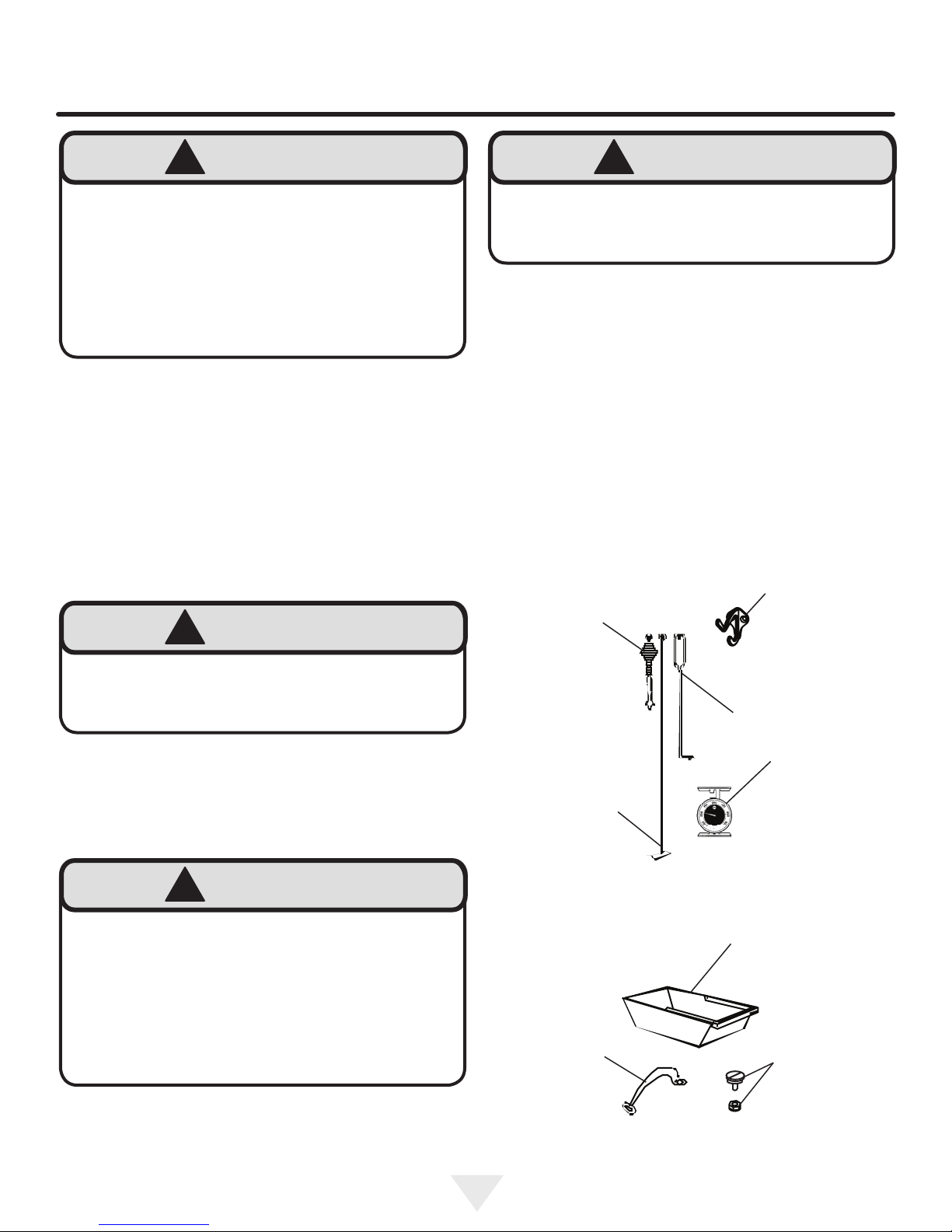
Unpacking
The warming shelf is secured to the skid with 2 screws and
a banding strap. The main stove body is strapped to the
skid. Smaller component parts are packaged as follows:
In the rebox:
1 ash scraper
The ash pan contains the following parts:
1 poker
1 tool rack
1 lid lifter
1 cooking surface lift handle w/screw and nut
1 interior oven thermometer
-Tool rack
!
WARNING
OVERFIRING CAUTION
Repeated or extended overring will void warranty on
this appliance. See page 29 for details.
!
WARNING
IMPORTANT:
Check around oven chamber on a weekly basis for
soot and creosote accumulation. Clean the chamber
thoroughly from the top, side and bottom with the ash
scraper provided. Burn the stove hot daily to reduce
creosote accumulation. Use only dry wood aged for
one year. Failure to do so could result in a chim-
ney re and void warranty.
Lid lifter-
Ash scraper-
Cooking surface
lift handle-
-Poker
-Interior oven
thermometer
Figure 3
-Ash pan
-Screw and nut
Figure 4
5

INSTALLATION INSTRUCTIONS
!
WARNING
WARNING- The stove is very heavy. Since
the legs may dig into a soft oor, do not locate the
stove, or even set it to rest, on a surface that could
be imprinted. We recommend that 3 or 4 persons be
available to assist in the lifting of the stove, and that
gloves should be worn to protect hands from cuts.
Unpacking:
1) Cut the banding holding the stove to the skid.
2) Remove the 3 screws at each corner which hold the
crate to the skid. (See crate diagram fastened to crate).
Lighten the stove by removing the keyplate and lids.
3) With 2 persons minimum on the heavier, rebox side
(left), and one person on the other side, lift the stove up,
off of the skid and onto its new location.
4) If possible, have a fourth person remove the skid while
the others lift.
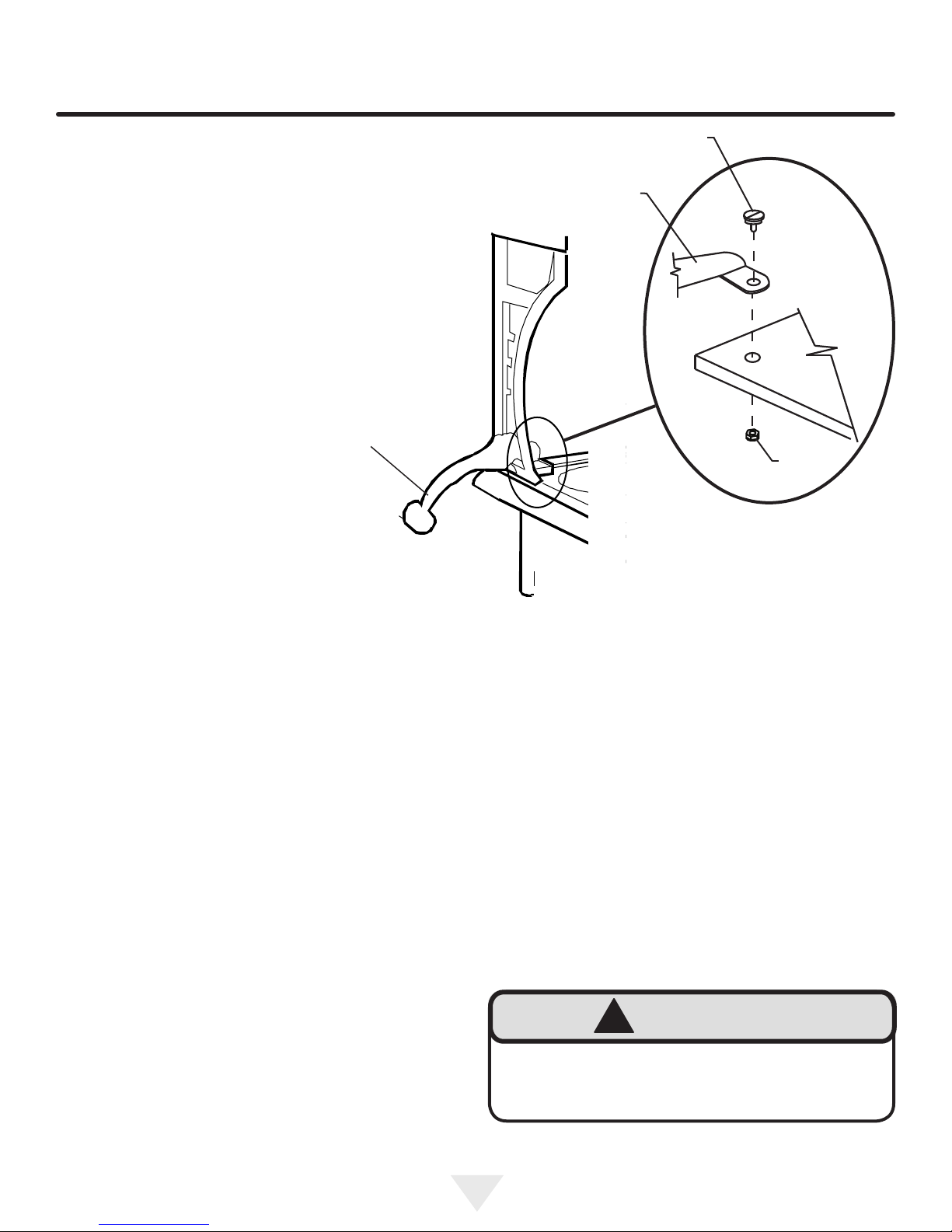
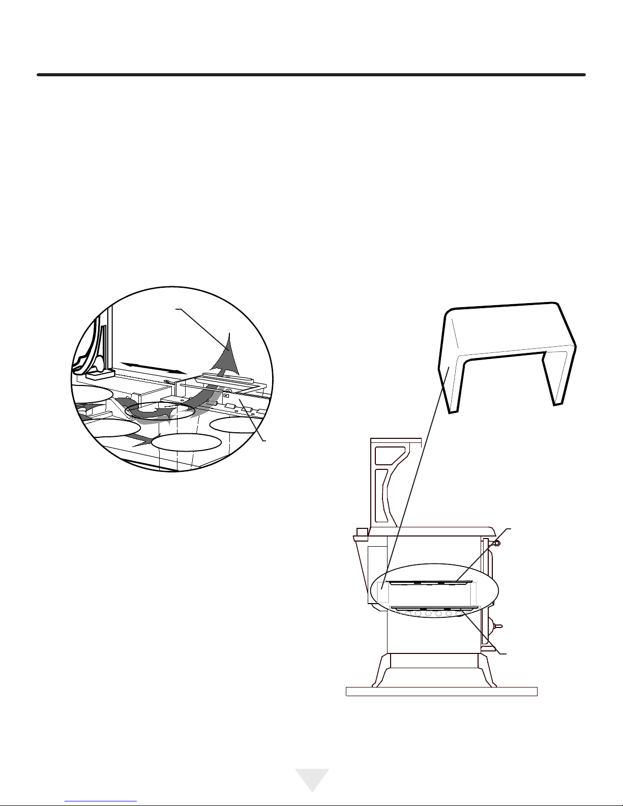
Shelf assembly to stove top:
Remember when working with the shelf it is top heavy.
Use your hand to support it during installation. Remove the
shelf assembly from the skid by removing the 2 screws and
cutting the banding strap. Lift the shelf assembly by the
bracket area that is circled and set on the oor or a table
top. Unwrap the shelf assembly.
Remove the washers and screws from the rear edge of the
stove top. (2 places). Also remove the 4 machine screws
from the top of the stove top.
With a helper lift the shelf assembly (by the circled bracket
area and supporting the top of the shelf) and place the shelf
into position on the stove top (see diagram above). Line up
the bracket holes with the 4 holes in the stove top while a
helper supports the shelf.
Secure the shelf to the stove top with the 4 machine screws
and the 2 screws and washers. To prevent chipping do not
overtighten screws or use power tools.
Tool Rack- fasten
to rear of shelf
using screws and
nuts provided.
Remove screws and
washers from top
back ange of top,
2 places
Remove machine
screws from the
top (2 each side)
Machine
Screw
Shelf
Bracket
Figure 5
6
INSTALLATION
Cooking Surface Lift handle installation:
Insert the lift handle through the left side shelf bracket and
secure it to the cooking surface with the screw and locknut
provided. (See gure 6).
Lift handle-
Screw
Lift
handle
Nut
Installation:
Be sure to read the sections on clearances, oor protection,
and chimneys before actively starting the installation.
Contact local building or re ofcials about restrictions and
installation in your area.
Clearances:
A woodburning stove radiates heat in all directions. Heat
directed toward living areas in front of the stove is usually
very welcome. However, heat radiating in other directions
will not be as welcome if it results in overheating nearby
walls, ceilings and oors.
An important part of planning a safe installation is to be
sure that combustible material located near your stove
does not overheat. Clearance is the distance between your
stove and stovepipe and nearby walls, ceilings, and oors.
If there is adequate clearance, then the nearby surfaces will
not overheat.
The clearance distance should be empty except for non-
combustible heat shields. Air owing between the stove and
stovepipe and nearby surfaces carries away heat. Do not
ll the empty space with any insulating material.
Figure 6
Be aware that as wood is exposed to continuous heat it
dries out, eventually lowering the temperature at which it
will start on re. Maintain the clearances outlined in this
manual, particularly with respect to nearby combustible
surfaces.
Your Heartland cookstove has been tested for safe operation providing that these guidelines are followed.
An optional heat shield kit is available for our woodstoves
for reduced clearances. See page 13 on "Heat Shield Kit"
!
WARNING
CLEARANCES must be maintained to all com-
bustible material. These include doors, trim, furniture,
drapes, newspapers, clothes, coal, and wood.
7
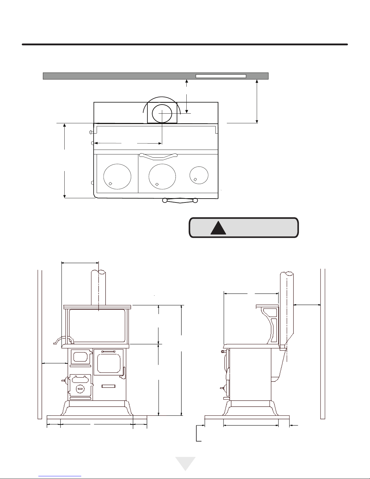
ROUGH IN AND DIMENSION DIAGRAMS
101⁄4" (26 cm) with heat shield kit #4241 (from wall to center of pipe)
23" (58.4cm) without heat shield (from wall to center of pipe)
181⁄4"
(46.4cm)
221⁄2" (57.2cm)
Combustible Wall
141⁄4" (36.2 cm) with heat
shield. 27" (68.6cm)
without heat shield to the
back of the stove top.
COMBUSTIBE WALL
(61cm)
24"
181⁄4"
(46.4cm)
Figure 7
(48.3cm)
(81.0cm)
19"
317⁄8"
These drawings are for reference only, showing approxi-
mate dimensions for rough in purposes. Make sure that no
oor or ceiling supports will be cut due to chimney installation.
507⁄8"
(129.2cm)
!
CAUTION
235⁄8"
(60.0cm)
20"
(51.0cm)
COMBUSTIBE WALL
HEARTH HEARTH
8"
(20.3cm)
30"
(76.2cm)
8"
(20.3cm)
Figure 8
21"
(53.3cm)
8"
(20.3cm)
16" (40.6cm) in U.S.
18" (45.7cm) in Canada
8
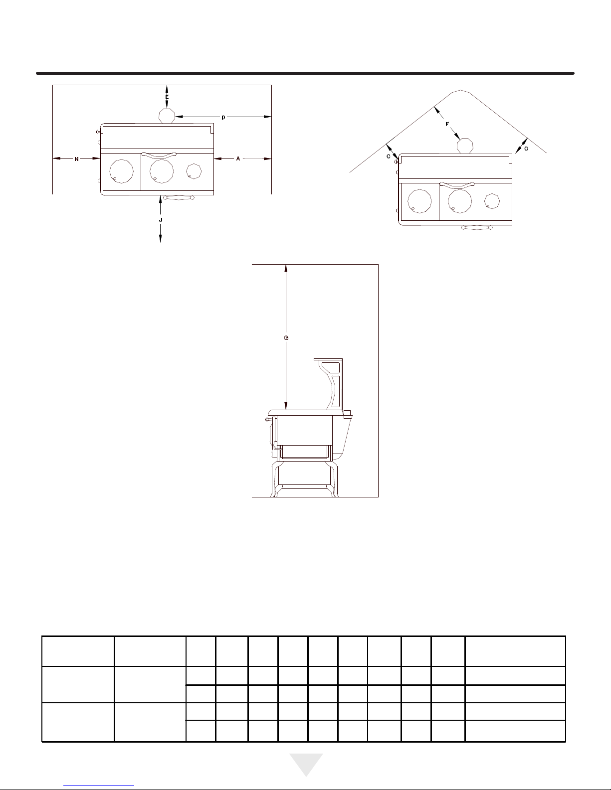
CHART OF CLEARANCES
When a heat shield is installed dimensions D, E and F are
taken from the heat shield. Dimensions A, C, G and H re-
main the same with or without a heat shield.
When two or more clearances to combustible walls
contradict each other, the clearance with the greater
numerical value must be maintained.
Status Model A C D E F G H J Measure
NO HEAT
SHIELD
WITH HEAT
SHIELD
BLACKWOOD
BLACKWOOD
25 66 66 51 58 132 61 121 Centimeters
10 26 26 20 23 52 24 48 Inches
25 66 132 61 121 Centimeters
10 26 52 24 48 Inches
Figure 9
61 5 31
24
2
9
12½

INSTALLATION
Clearance Reductions
There are many alternate decorative methods to reduce
clearances to combustible materials. See your dealer,
or local re or building ofcial to assure the appropriate
standards are being met with these alternatives. In Canada,
refer to the Installation Code for Solid Fuel Appliances
and Equipment. CAN3-B365-M84. In the U.S., refer to the
National Fire Protection Association Standard 211.
Floor Protection
When installing your woodstove on a combustible oor, a
non-combustible oor protector is required under the stove
to protect the oor from hot embers that may fall when
reloading. The oor pad must be a continuous, non-combustible pad (oor tile with grouting or a sheet metal pad). A
oor pad should not be placed on top of a carpet. Pad must
extend 18" (458mm) in front of the stove in Canada and
16" (407mm) in front of stove in U.S. Pad must extend 8"
(203mm) to the sides and back of the stove.
Pad must extend fully to the wall if using side and back
clearances less than these dimensions. Pad extension
must be fabricated from non-combustible materials:
1/2" (13mm) thick minimum with thermal conductivity factor
"K" of 0.43 or lower (units of K = btu/h/F/in).
To determine thickness of equivalent material required
use formula ("K" x 0.5) / 0.43 = thickness required ("K" value can be obtained from manufacturer of oor material).
Chimneys and Draft
The chimney is the most important element of successful
stove operation. (See also page 24 "Flue Pipes")
Performance of your woodburning system depends
more on the chimney than on any other single
component.
The chimney 'drives' the system by producing the draft that
draws in combustion air and exhausts smoke and gases to
the outdoors.
When installing a new woodburning system or upgrading
an existing one, give as much attention to the chimney as
you do to the appliance that it serves.
DO NOT CONNECT THIS UNIT TO A CHIMNEY FLUE
SERVING ANOTHER APPLIANCE.
This room heater must be connected to:
(1) a listed Type HT (2100°F) chimney per UL 103 or ULC
S629, or
(2) a code-approved masonry chimney with a ue liner.
The chimney size should not be less than or more than
three times greater than the cross-sectional area of the ue
collar.
Follow the chimney manufacturer’s directions for installation. We recommend that prior to installing your stove into a
masonry chimney, you have the chimney inspected by a
qualied mason. An unlined masonry chimney should not
be used without the installation of a liner.
The chimney and installation will have to be inspected by
your local building inspector.
10
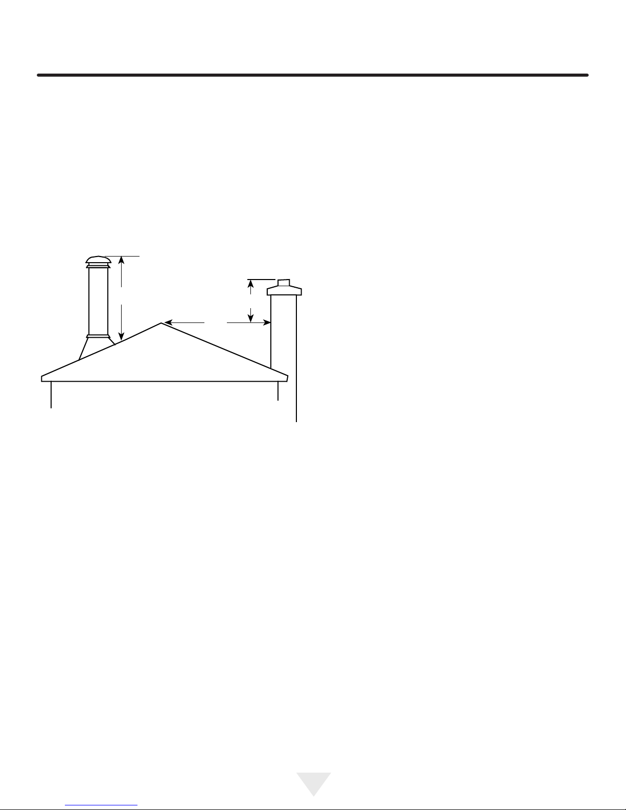
CHIMNEYS AND DRAFT
Recommended Chimney Clearances
The chimney must:
• extend at least 14 ft. (4.27m) above the collar of the
stove;
• extend at least 3 ft. (92 cm) above the point where it
passes through the roof;
• be at least 2 ft. above anything within a 10 ft. (3.048m)
radius of the top of the pipe.
Good draft in a cold chimney should be between
0.01" and 0.15" "water column" (your dealer may be
able to check this for you).
36" (900mm)
Figure 10
Illustration showing minimum heights required,
depending on the chimneys location.
24" (600mm)
10 Feet
(3 meters)
Stovepipe Chimney
Connection Requirements
1) The stovepipe chimney connector should be made of 24
gauge or thicker sheet metal and should be 6" in
(15.24cm) diameter.
2) The last section of the chimney connector starting from
the stove should be screwed to the ue collar of the
stove. Individual sections of the chimney connector must
be screwed together with at least three sheet metal
screws. The last section should be securely attached to
the chimney. Be sure there are no "weak links" in the
system.
3) The crimped ends of pipe sections should point down-
ward toward the stove so that any soot or creosote that
falls from the inside of the pipe will be funnelled into a
clean out or fall into the stove.
4) The chimney connector should be at least the height of
the warming shelf before a 90 degree turn is installed,
with no more than two 90 degree turns.
5) A horizontal run of stovepipe should be no longer than 4
ft (1.22m). A vertical run of stovepipe to a prefabricated
metal chimney should be no longer than 8 ft (2.44m).
6) Do not pass the stovepipe chimney connector through
a combustible wall if it can be avoided. If this cannot
be avoided, follow the recommended in CSA B365 in
Canada and NFPA 211 in the U.S., recommendation on
Wall Pass-Throughs.
7) Do not use single wall smokepipe as an outside chim-
ney.
8) Never pass stovepipe chimney connector through a
combustible ceiling.
9) The whole chimney connector should be exposed and
accessible for inspection and cleaning.
10) Galvanized stovepipe should not be used. When ex-
posed to the temperatures reached by smoke and
exhaust gases, galvanized pipe may release toxic
fumes.
11) Horizontal runs of chimney connector should slope
upward 1⁄4" (6.35 mm) per foot going from the stove
toward the chimney.
12) During a chimney re, the chimney connector may
vibrate violently. The connector must be securely
attached to the pipe and chimney, and individual
sections must be securely attached together.
13) This stove is not to be connected to an air distribution
duct.
11
CHIMNEYS AND DRAFT
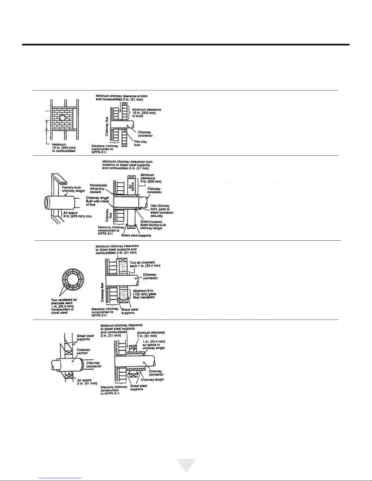
Chimney Connector Systems and Clearances
from Combustible Walls for Residential
Heating Appliances:
Figure 11
Minimum 31⁄2" thick brick masonry all framed into combustible wall with a minimum of 12" brick separation from clay
liner to combustibles. The reclay liner shall run from outer
surface of brick wall to, but not beyond, the inner surface of
chimney ue liner and shall be rmly cemented in place.
Figure 12
Solid-insulated, listed factory-built chimney length of the
same inside diameter as the chimney connector and hav-
ing 1" or more of insulation with a minimum 9" air space
between the outer wall of the chimney length and combustibles.
Figure 13
Sheet steel chimney connector, minimum 24 gauge in thick-
ness, with a ventilated thimble, minimum 24 gauge in thickness, having two 1" air channels, separated from combustibles by a minimum of 6" of glass ber insulation. Opening
shall be covered, and thimble supported with a sheet steel
support, minimum 24 gauge in thickness.
Figure 14
Solid insulated, listed factory-built chimney length with an
inside diameter 2" larger than the chimney connector and
having 1" or more of insulation, serving as a pass-through
for a single wall sheet steel chimney connector of minimum
24 gauge thickness, with a minimum 2" air space between
the outer wall of chimney section and combustibles. Mini-
mum length of chimney section shall be 12" chimney section spaced 1" away from connector using sheet steel sup-
port plates on both ends of chimney section. Opening shall
be covered, and chimney section supported on both sides
with sheet steel supports securely fastened to wall surfaces
of minimum 24 gauge thickness. Fasteners used to secure
chimney section shall not penetrate chimney ue liner.
12
OPTIONAL ACCESSORIES
Accessories may be obtained from your dealer or call us
direct at 800-223-3900. Our ofce hours are from 8:00 a.m.
to 5:00 p.m. est.
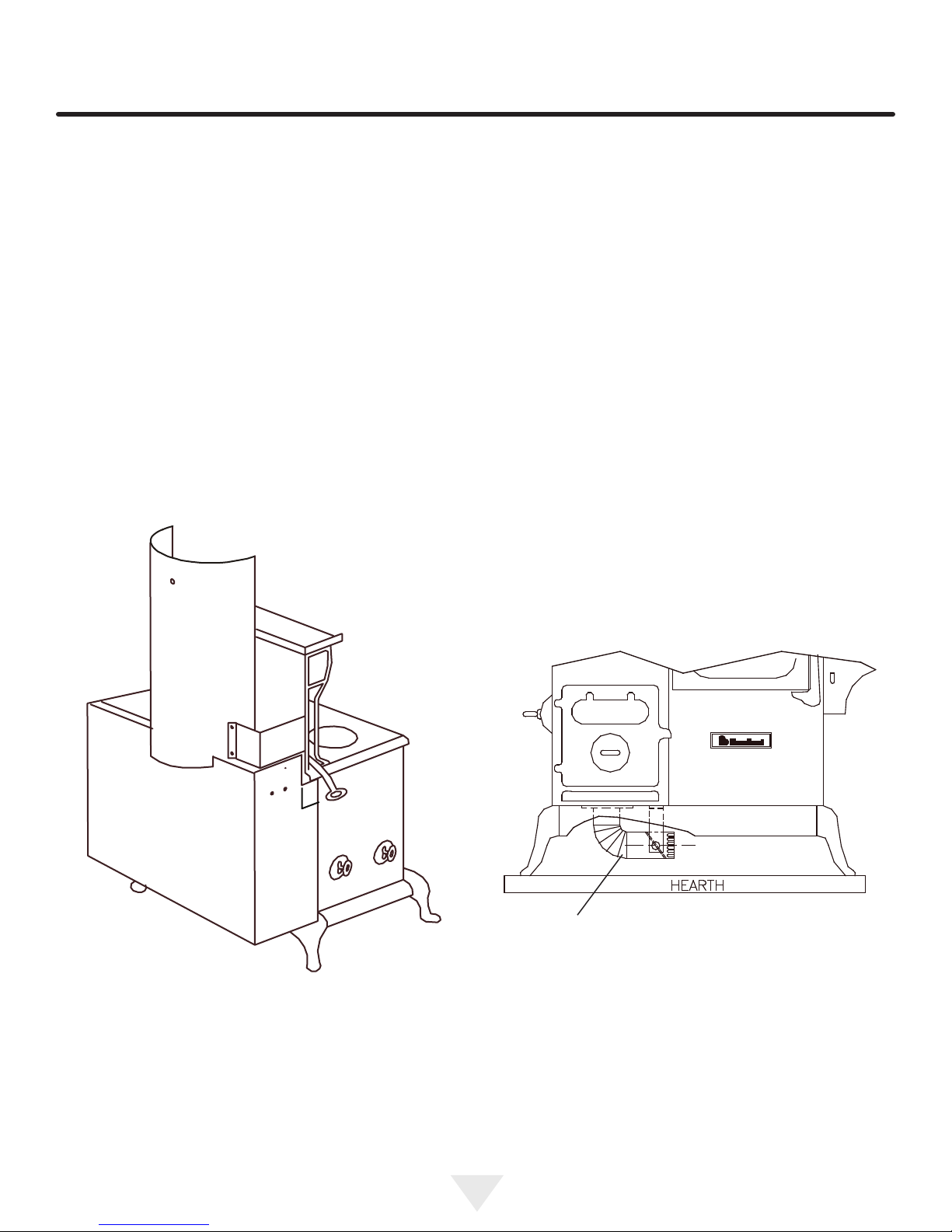
Heat Shield Kit #4241
A space saving heat shield kit enables you to install your
cookstove as close as 2" (5.1cm) to a combustible wall!
Installation is Easy
The heat shield kit is available for the cookstove and
mounts directly on the rear of the stove. The main section
of the shield covers the rebox and oven of the cookstove,
while the upper section covers the u pipe to a height
above the warming shelf.(See illustration, Figure 15.) An
installation and operating manual is packed with every heat
shield kit. Extra copies may be obtained from your dealer or
by contacting AGA Marvel.
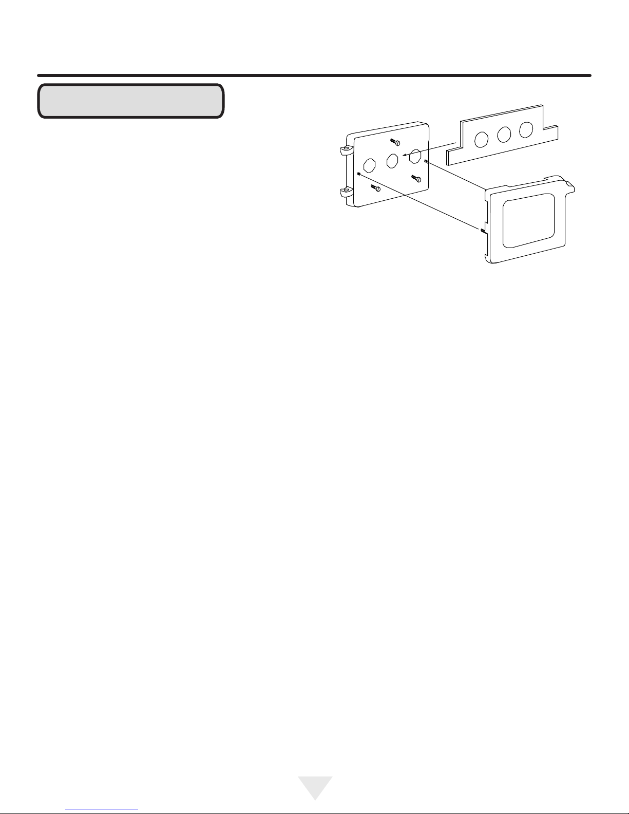
Fresh Air Kit #1017
A fresh air kit enables you to use outside air, instead of
room air to fuel the re. Using an outside source for com-
bustion air has its advantages. If your home is tight and
well insulated, then the re in the stove may be "starved" of
combustible air, it will be difcult maintaining a re, and you
may have back drafting problems.
During the heating season, cold air, (which is more dense
than warm air), will cause the re to burn a little hotter, resulting in more BTU’s from your wood, and less creosote
build-up.
Installation is Easy
Mounting holes and airways are all pre-punched on the
cookstove.(See gure 16). Simply remove the cover plates
on the bottom of the rebox. Now you are ready for installation. A complete set of diagrams and instructions are included with each fresh air kit. Please note that some States
require a fresh air source to be installed with wood burning
appliances. Please check your local, and state, building
codes.
Figure 15
Illustration of heat
shield kit
s
Fresh air kit-
Figure 16
Illustration of Fresh air kit
13
OPTIONAL ACCESSORIES
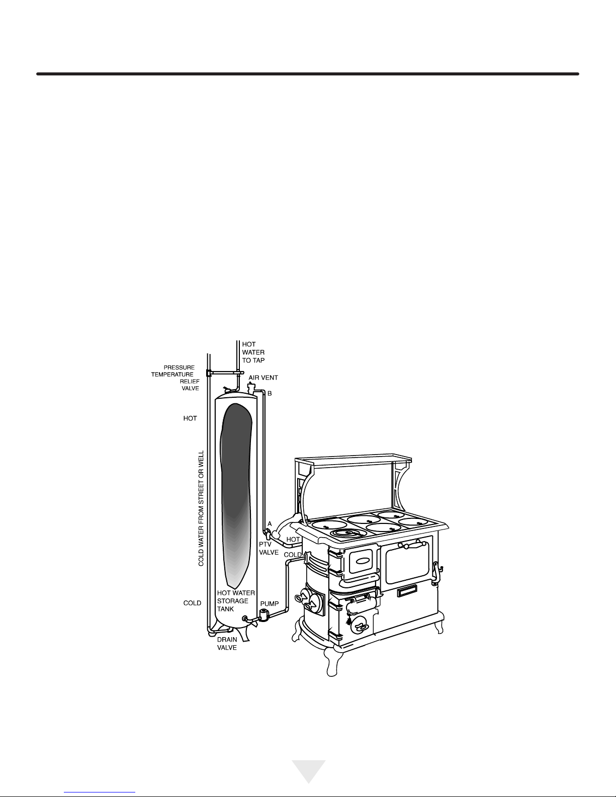
Water Jacket Kit #4506
The average family spent about one quarter of their utility
bill to heat water last year. By installing the water jacket in
your cookstove, you can reduce or virtually eliminate your
hot water utility bill.
Installation is Easy
The water jacket can be installed in the stove using only a
slot screwdriver. The water jacket is a hollow bafed chamber that ts in the rebox. Two pipes and a pump installed
from the water jacket to the electric or gas water heater,
circulate heated water from the stove to the storage tank.
(See illustration, Figure 17.)
You can expect from 6 to 8 gallons (22.7 to 30.3L) or more
hot water per hour (about 8,000 BTUs) from your water
jacket.
Because cold water cools the water jacket in the rebox,
creosote will be attracted to its cool surface, like humidity
being attracted to a cold window.
These deposits will quickly burn off thus reducing creosote
formation in the stove and chimney.
An installation and operating manual is packed with every
water jacket. Extra copies may be obtained from your dealer or by contacting AGA Marvel. (See page 30).
This is an illustration of an active or pumped
Figure 17
A Sample Water Jacket Installation
circulating hot water system.
14
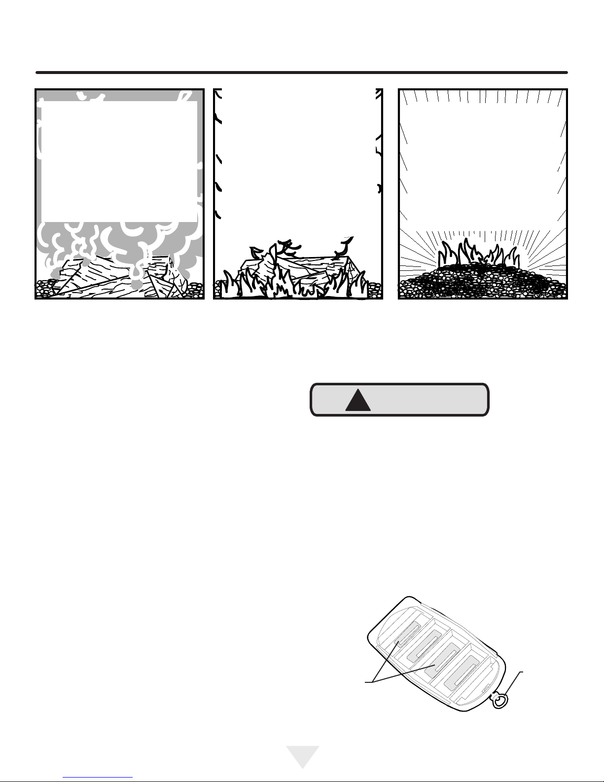
Water: Up to half the weight of
freshly cut logs is water. After
proper seasoning only about 20%
of the weight is water. As the wood
is heated in the rebox, this water
boils off, consuming heat energy in
the wood, the more heat energy is
consumed. That is why wet wood
hisses and sizzles while dry wood
ignites and burns easily.
UNDERSTANDING COMBUSTION
Smoke (or ame): As the wood
heats up above the boiling point
of water, it starts to smoke. The
hydrocarbon gases and tars that
make up the smoke are combustible if the temperature is high
enough and oxygen is present.
When the smoke burns, it makes
the bright ames that are characteristic of a wood re. If the smoke
does not burn, it will condense in
the chimney forming creosote or
exit the chimney as air pollution.
Figure 18
Charcoal: As the re progresses
most of the gases have vapor-
ized, charcoal remains. Charcoal
is almost 100% carbon and burns
with very little ame or smoke.
Charcoal is a good fuel that burns
easily and cleanly when enough
oxygen is present. Of the total
energy content of the wood you
burn, about half is in the form of
smoke, and half is charcoal.
Break In Fires for New Stoves:
If this is your rst re, OR you have installed a replacement
set of brick, read the procedure for break-in res. Proper
seasoning ensures longer stove life.
Woodburning:
The rewood you use will make an important contribution
to successful operation. You will achieve the best perfor-
mance and overall efciency by burning rewood that has
been split, stacked and air-dried undercover from rain for
at least one year. Burning improperly seasoned or "green"
wood can be a frustrating experience leading to poor per-
formance, smoky res and a build-up of creosote. Do not
burn saltwater driftwood refuse, rubber tires, etc. Use of
improper fuels can cause a re hazard and lead to a premature deterioration of the stove components, voiding the
warranty. (See Figure 18, Understanding Combustion.)
Burn dry wood because:
• It gives up to 25% higher efciency;
• It produces less creosote;
• It ignites faster and smokes less;
• Valuable heat is lost in the re as it dries out wet wood.
Before starting the stove, lift the key plate handle and rest
the arm in the top hook of the shelf bracket. Open both
the top loading and ash pan doors. The doors open by lifting slightly over the hook and pulling towards you.
!
CAUTION
Always use the lid lifter to open doors and bell dampers and when adjusting the oven damper.
In the cookstove, looking into the rebox through the top
you will see rebrick liners on the left and right side of the
rebox.
At the bottom of the rebox is the wood grate, looking in
through the ash pan door, you will see the wood grate
pull—slide it back and forth and looking down into the re-
box you will see the slots open and close.
Getting Acquainted:
This cookstove is a time proven heating and cooking appliance. Take your time to acquaint yourself with the principles
on which your new stove operates as a heater and cooking
stove.
Understanding the primary principles of the air intake
controls, the oven damper, the ame path for the re and
the relationship to the chimney will give you a very comprehensive understanding of what you are trying to accomplish
with the stove.
15
Slots, open
and close
Wood
grate pull
Figure 19
UNDERSTANDING COMBUSTION
The stove is burned with the slots open which allows the
combustion air to enter underneath the re. As ash and
coals build up on the grate these slots ll and will require
the occasional "shaking".
It is a good policy to shake the grate or stir the coals with
the poker before loading a new charge of wood.
You will notice that with the ash door closed the ash ap
may be lifted to access the wood grate pull without having
to open the door.
Burning skid wood or construction materials with nails is not
recommended as anything in the rebox that will not burn
has the potential to get caught in the grate.
The ash pan is directly below the grate.
Starting the Stove:
Good safety practices:
Wood grate pull
Bell damper
Lid Lifter Functions
Figure 20
!
WARNING
Educate your family members:
• Before burning the stove, have each family member
read this manual and be aware of safety practices.
• Keep children, clothing and furniture away from the
stove.
• The stove is HOT while in operation – DO NOT
TOUCH the stove, contact may cause burns.
• Open the redoor, ash pan door, woodgrate pull,
bell dampers and oven damper with the 1415 lid lifter
only—these surfaces get hot; (see gure 20 and 21).
• Keep a class A re extinguisher nearby and have a
clearly understood plan on how to extinguish a re.
• Make sure you have a high quality smoke detec-
tor in your home. Check with your local building
code authority for more information.
Oven damper slide
Figure 21
!
CAUTION
Never use gasoline, gasoline-type lantern fuel, kerosene,
charcoal lighter uid, or similar liquids to start or 'freshen
up' a re in this heater. Keep all such liquids well away
from the heater while it is in use.
16

UNDERSTANDING COMBUSTION
Break-In Fire
(Refer to page 15 gure 18)
The rebox of your stove is made of superior materials—
cast iron and rebrick lining.
Both materials could be broken by a sharp blow or thermal
shock. A little extra care and thoughtfulness during the
breakin period will help promote a long life for your stove.
The cast iron and rebrick will have picked up moisture during shipping and storage.
During the break-in period it is important to let the cast iron
and rebrick slowly dry out and avoid thermal shock,
caused by strong hot res.
• Build a small kindling re (following the instructions
below for the rst re) and add small pieces of
kindling. Let the stove burn for approximately one
hour on the rst ring.
• Let the stove cool keeping the doors closed.
• Repeat the process for a few days or until you have
had six break-in res. You may notice some smoke
or "burnoff" during your initial ring. This is normal
and is caused by the curing of the paint nish.
Your First Fire
It is advisable to read and understand this section thor-
oughly before starting the re (Refer to page 15 gure 18).
1. Open the oven damper (see Figure 22) and air intake
controls (bell dampers). On damp cold days, it may help
to open the ash door slightly until a good draw develops
in the chimney.
Light the paper at the bottom of the load and then light
the paper at the top, shut the key plate immediately. You
may nd it helps to hold the key plate open just slightly
for a few seconds to give some extra air and establish
the re.
3. To Fuel the Fire. After a couple of minutes open the front
loading door slowly. When the kindling is established add
larger pieces, perhaps 2"x2"x10" (5cm by 5 cm by
25.4 cm) long.
Continue this process until the re is established when
split logs can be added.
Dampering the stove. Tighten the bell dampers to
approximately 1⁄4" (6.35 mm) opening. This will slow
the re down. Wait momentarily and close the oven
damper.
The smoke and heat is now being routed around the
oven. Remember, by closing the oven damper resistance
has been put on the system.
If the stove/chimney is not yet heated enough or there
is too much volume of re going through, this additional
resistance will cause backpufng.
Close the oven damper slowly (Fig. 18) to allow the oven
ue chamber to absorb the smoke and heat.
4. Reloading the stove—Stove tending time will be greatly
reduced if you reload your stove while the system is still
hot and there is plenty of hot embers to rekindle the re
quickly. Including some smaller pieces of wood in the
new fuel load will help the stove regain temperatures
quickly.
2. To kindle a re. Lift the key plate lift handle and rest it
in the top slot of the closet bracket. Crumple six to eight
single sheets of newspaper into loose balls and place
them on the wood grate. Cut 10-15 pieces of kindling into
strips approximately 1/2" by 1/2" by 10" long (1.27 cm by
1.27 cm by 25.4 cm).
Place the kindling on the newspaper. Place 2 or 3 more
pieces of crumpled newspaper on top of the kindling.
Ensure that the wood grate slides are open.
Lighting the ‘charge’ is of your personal preference. One
method is to roll a piece of newspaper into a torch, light-
ing one end and using it to start the paper.
When reloading, open the oven damper and wait
momentarily—if loading from the top—slowly lift the key
plate or if loading from the front, open the door slowly.
Load wood—smaller, split pieces rst.
Close the door or key plate.
Open the bell dampers slightly.
The stove must rebuild its thermal momentum before
closing the oven damper.
As you become more experienced you will gain knowl-
edge on what settings of bell dampers and oven damp ers can be used at the different stages of the woodburn-
ing cycle (see Combustion Process, page 15 gure 18).
17
UNDERSTANDING COMBUSTION
An "Airtight" House:
If your home is well insulated or especially well sealed, the
inltration air supply to the interior of the house may be in-
adequate. This phenomenon of air starvation can be exac-
erbated if exhaust fans (such as clothes dryers, bathroom
fans, or cook stove exhaust fans) are used in your home.
Outtting your stove with the optional fresh air kit adapter,
connected to an air duct leading to the outside of your
home, should correct this problem.
Flue Gases
Oven
Damper
Figure 22
Oven Damper Open
Summer Burning:
The cookstove features a utility which allows you to use
your stove during the summer months with less heat radiat-
ing from the rebox.
To use the summer position in the Blackwood you will need
to purchase the optional #4271 summer grate support. Call
your dealer to order, or call direct to AGA Marvel.
1. Remove the wood grate from the lower rebox position
by pulling the grate up, back end rst, and out of the
rebox.
2. Remove the wood grate slide from the wood grate. Place
the "summer position wood grate stand" at the back of
the rebox on the rebox extension.
3. Place the re grate so the back of the re grate rests on
the stand, and the front rests on the top of the front brick.
You are now ready for summer cooking.
Blackwood
summer
grate stand
Upper "Summer
position".
Lower "Standard position".
Figure 23
Wood grate positions
for the blackwood stove
18
NOTE
COAL BURNING
NOTE-A series of wood "break in" res should be done
before attempting to burn coal (see page 17).
Coal Burning:
Do not burn coal on the wood grate. An optional coal grate
kit is available for the cookstove (#4500) to burn coal. An
installation and operating manual is packed with every
Blackwood Coal Kit. Extra copies may be obtained from
your dealer or by contacting AGA Marvel. Below is a brief
description of the coal kit installation.
Storage of Coal:
Store coal in a dry, well ventilated area.
Coal Grate Installation:
To install the optional coal grate, remove the lift handle, the
key plate and lids. Lift the wood grate out through the top
of the rebox and replace it with the coal grate. Remove
small front brick in rebox by unscrewing bolt & nut that
holds brick in place. Replace with large brick in coal kit.
Gently tap the coal grate down until it ts snugly into the
steel track. Replace the key plate, lift handle and lids. Then
proceed with redoor damper installation.
Firedoor Damper
(Coal burning only, see Figure 24.)
O
C
Figure 24
Illustration showing
redoor
damper installation
Starting Up a Coal Fire
A chimney 6" (15.25 cm) in diameter is imperative for the
Coal Burning process. A chimney larger than 6" (15.25
cm) in diameter will cause poor ignition of the coal due to
inadequate draft.
It is possible to burn coal with a large diameter chimney,
but banking a new bed of coals will require a greater mix of
wood to create and maintain an adequate draft.
The minimum draft required to maintain an oven tempera-
ture of 350º F (175C) is around .04" (1.016 mm) on a water
column. For drafts under .04" (1.016 mm) on a water column, closing the oven draft damper more than half way, will
cause back pufng.
The redoor damper comes with each coal kit and must be
installed. Remove the black redoor frame from the re-
door. Loosen the three screws that hold the cover plate
over the damper holes. Replace the cover plate with the
coal damper, lettered side out. Tighten screws just enough
to hold the damper plate on but also allow it to slide freely
back and forth. Lock screws in position with a nut on each
screw thread.
During the recharge phase of a new bank, a draft of .08"
(2.03mm) should be maintained for at least 10-15 minutes
or until a substantial bed of red embers is built up.
We recommend burning anthracite coal, which is relatively
clean to handle, burns evenly with a low ame, has a low
sulphur content and produces relatively little smoke.
Use a "chess nut" or "nut" size of coal, which is 13⁄16 to 15⁄8
in (3 cm to 4.13 cm) diameter. However, other coal, such as
bituminous, can be burned, but is inferior to anthracite.
To Start a Coal Fire:
1. Use paper and dry wood kindling to start the re.
2. Add small, compact pieces of hardwood when the kin dling is burning hot. Keep the primary damper controls
fully open to establish a hot re quickly. The ash door
also may be opened during start-up to accelerate the
initial burn.
3. When a substantial bed of red embers is built up, start
adding coal – small amounts at a time. Keep the draft
control open.
19
COAL BURNING
4. Continue adding small amounts of coal until there is a
solid bed of burning coal. Do not add too much at one
time. Allow sufcient time between each small loading (at
least ve to ten minutes), so that each loading has time
to ignite thoroughly before the next load is put in.
When a substantial bed of burning coals has been
established, ll the stove to the highest possible level,
no higher than the bottom of the redoor – be careful not
to overload! A deep bed of coal will always burn more
satisfactorily than a shallow bed.
5. When most of the wood is burned and the coal is com pletely ignited (usually ve to ten minutes or less after
lling the stove), the draft control should be turned down
to the proper operating level. (If the ash door has been
opened, it must be closed to prevent overring, which
can severely damage the stove.)
Recharging the Fire:
If the re is burning hot and there is a deep bed of coals,
add coal a hand full at a time.
Allow enough time between each addition for the combustion process to start. As the bank becomes larger, the
amount of coal added at a time can be increased.
Soot - Formation and Need for Removal:
When coal is burned, the products of combustion combine
with moisture to form a soot residue, which accumulates
on the ue lining. When ignited, this soot makes an extremely hot re. When burning coal, the chimney connector
and chimney should be inspected at least once every two
months during the heating season to determine if a soot
buildup has occurred.
Disposal of Ashes (wood and coal):
Do not remove the ash pan when the stove is hot. Carry
the ash pan with one hand on the handle in the upright
position and the other on the front edge of the pan to balance the pan.
Empty the ash pan before ashes build up over the top.
Improper disposal of ashes is the most common cause of
wood stove related res.
If the coal bed is under 5" (12.7cm) before a recharge is
started, it may be necessary to add kindling wood to in-
crease the combustion level so that more coal can be
added.
1. Coal never should be added unless there is a reasonably
hot re. The coal bed should be bright and vigorous.
2. If the re is burning hot and there is a deep bed of coals,
full loads of coal can be added at any time. However, if
there is not a deep bed of coals, it is best to add small
amounts of coal at rst.
NOTE
When burning coal, the redoor damper must be kept open.
The secondary air is required to aid in burning off coal
gases. The coal damper is not required when burning wood
and should be kept closed when burning wood.
Coal grates are not to be used in upper (summer) position.
Do NOT ll rebox with coal higher than the bottom of the
redoor opening.
Disposal of Ashes - Ashes should be placed in a metal
container with a tight tting lid. The closed container of
ashes should be placed on a noncombustible oor or on
the ground, well away from all combustible materials, pending nal disposal. If the ashes are disposed of by burial in
soil or otherwise locally dispersed, they should be retained
in the closed container until all cinders have thoroughly
cooled.
!
CAUTION
• Don’t carry hot ashes through the house.
• Even though the stove may be cool, the ashes in the pan
may still be hot.
• Never place the ash pan on a combustible oor.
• Never leave the ashes near combustible material or com-
bustible liquids.
• Always dispose of ashes in a closed metal container with
a tight tting lid—if an unexpected gust of wind fan the
ashes, a re could result.
20
 Loading...