

Page 1
HEARTLAND
1050 Fountain St N. Cambridge, Ontario, Canada N3H-4R7 Phone: 1-877-650-5775
Cabinet Installation Instructions
For Gas, Electric, Combination and Wood
Stoves
For 48" Models: 7200, 6200, 6210, 5200, 5210,
30" Models: 9200, 8200, 8210, 4200, 4210
Wood Stove Models: 1903, 1902, 2603, 2602
Please Read These Instructions Thoroughly
Before Installing Your Cabinet.
English Edition
Note: If you plan to vent your exhaust hood to the outside, please refer to your range's Owner
Installation and Operating Instructions under Exhaust Hood section before completing this
installation. Note: maximum run of ducting is 25 linear feet (subtract 5' per 90 deg
elbow added to the exhaust line and 2.5' per 45 deg elbow)
Before proceeding, check for damage that may have occurred during shipping. If the
contents are damaged, inform the freight company or your dealer immediately!
Please refer to the "Installation and Operating Instructions" manual to complete your range installation
101507
#1719
© 2007 AGA-HEARTLAND
Page 2

T ABLE OF CONTENTS
1. Removing Cabinet from Box........................................................... 2
2. Assembly of Cresting panel............................................................ 3
3. Installing Cabinets for Electric and Combination Stoves ............... 4
4.Installing Cabinets for Gas Stoves ................................................ 5
5. Installing Cabinet for Wood Stoves................................................ 6
6. Venting .......................................................................................... 7
7. Connecting Power to the Cabinet for
Electric and Combination Stoves ....................................................... 8
8.Connecting Power to the Cabinet for Gas Stoves .......................... 9
1
Page 3
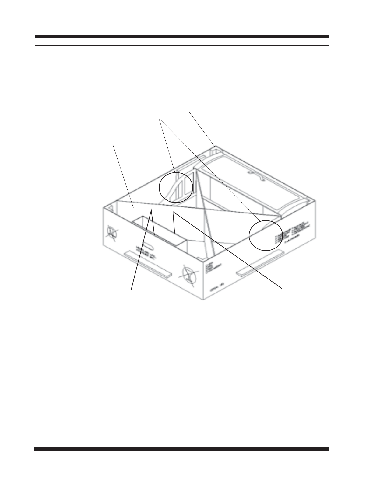
Please read through these instuctions before installing the cabinet on the stove base.
TWO PEOPLE ARE REQUIRED TO DO THE INSTALLATION
Cardboard
corners
Lift here
Cardboard
Cross brace
Small boxcontains:
- hardware package
- deflector ( not included with woodstove
cabinets.)
- 3 1/2"x10 exhaust adapter ( not included with
woodstove cabinets.)
The cabinet comes assembled , except cresting panel (see next page for assembly
instructions) and only requires attachment (installation) to the base of the stove. Further
assembly of optional venting of the exhaust fan may be required.
Before removing the cabinet assembly from the box, make sure you :
- Remove the 4 cardboard corners.
- Remove small box and its contents.
- Remove the cardboard cross brace.
- Remove the plastic wrapped cresting panel.
Cresting panel
packed in plastic
bubble wrap
Fig. 1
2
Page 4

Main Cabinet
Assembly of Cresting Panel.
view of top of cabinet
Wingnut
Cresting Panel
Locate cresting panel packed in bubble wrap.
Unwrap the cresting panel and remove the wingnuts.
Place the cresting panel on the rear of the top of the cabinet.
Take the wingnuts and fasten the cresting panel to the cabinet through the holes at each
end of the cabinet. For:
WOOD STOVES - go through the cabinet door.
GAS, ELECTRIC & COMBINATION STANDARD OR SELF CLEAN STOVES - go through
the filter openings.
(NOTE: if your cupboards are too low the cresting panel may be left off).
3
Page 5

ELECTRIC AND COMBINATION STOVES ONLY
Sheet metal
screw
Steel washer
STOVE
Machine screw
Bracket
Gasket - Peel off backing
and stick on.
Steel Washer Machine screw
-Remember when working with the cabinet, the cabinet is top heavy. Use your hand to support it during
installation.
-Place box on the floor close to stove. (See Fig. 1 Page 2).
-With a helper,lift cabinet assembly from box by area that is circled.(See Fig.1 Page 2).
-Rest the cabinet assembly on the carton,while your helper steadies the cabinet,peel the cabinet backing off the
gasket and stick one on each bracket.
-Place cabinet assembly onto stove body.(See diagram above)
Caution: In the case of the Glass cooktop models 8200, 8210, 6200, 6210:
DO NOT REST CLOSET CORNER BRACKETS ON GLASS, to prevent damage to glass top
-Line up holes in the bottom (foot) of the bracket with the holes in the stove top,while one person supports the
cabinet, fasten the cabinet brackets to the stove top with machine screws .
-To fasten the splashback to the rear of stove, with the Models 5200, 5210, 6200, 6210 use 5 sheet metal
screws and washers. For Models 4200, 4210, 8200, 8210 use 4 sheet metal screws and washers. To prevent
chipping do not overtighten or use power tools.
Sheet metaI
screw (black)
(Nickel Plated)
TOP
Gasket
4
Page 6

GAS STOVES ONLY
(WOOD STOVES SEE NEXT PAGE)
Sheet metal
screw
Steel washer
48" models only-right
brackel front screw
attachment:machine
screw attached to stove
top without use of nut.
STOVE
Machine screw
TOP
Bracket
Gasket - Peel off backing
and stick on.
Nut
Steel Washer Nut Machine screw
-Remember when working with the cabinet, the cabinet is top heavy. Use your hand to support it during
installation.
-Place box on the floor close to stove. (See Fig. 1 Page 2).
-With a helper,lift cabinet assembly from box by area that is circled.(See Fig.1 Page 2).
-Rest the cabinet assembly on the carton,while your helper steadies the cabinet,peel the cabinet backing off the
gasket and stick one on each bracket.
-Place cabinet assembly onto stove body.(See diagram above)
-Line up holes in the bottom (foot) of the bracket with the holes in the stove top,while one person supports the
cabinet, fasten the cabinet brackets to the stove top with machine screws and nuts.
-To fasten the splashback to the rear of stove, with the Model 7200 use 5 sheet metal screws and washers.
For Model 9200 use 4 sheet metal screws and washers. To prevent chipping do not overtighten or use
power tools.
Sheet metaI
screw (black)
(Nickel Plated)
Gasket
5
Page 7

WOOD STOVES ONLY
Remove machine screws
from the top (2 each side)
Machine screw
STOVE
TOP
Bracket
Screwdriver
-Place box on the floor close to stove. (See Fig. 1 Page 2).
-Remove the nuts, washers and screws located at rear edge of stove top (2 on SWEETHEART,4 on
OVAL) and the 4 machine screws from the stove top.
-With a helper, lift cabinet assembly from box by area that is circled. (See Fig. 1 Page 2).
-Place cabinet assembly onto stove body. (See diagram above).
-Line up holes in the bottom (foot) of the bracket with the stove top holes while one person supports
cabinet, fasten the cabinet brackets to the stove with machine screws (2 each side). (See diagram
above).
-Re-insert screws from the inside of the lip at the back of stove through the splashback , then
assemble the nuts and washers to each screw (2 on a SWEETHEART 4 on OVAL). Tighten nuts to
a snug fit. To prevent chipping do not overtighten or use power tools.
6
Page 8

GAS, ELECTRIC AND COMBINA TION STOVES ONL Y
Deflector
Back of cabinet
Sheet metal
screw
If you are not venting outside, attach the deflector to the rear of cabinet with 4, sheet metal
screws. If you are venting outside, attach the 3 1/2" x 10" exhaust adaptor with 4, sheet metal
screws. Fasten your exhaust ducting to the adaptor.
Note: maximum run of ducting is 25 linear feet (subtract 5' per 90 deg elbow added to
the exhaust line and 2.5' per 45 deg elbow)
3 1/2" x 10" Exhaust adaptor
7
Page 9

CONNECTING POWER TO THE CABINET
COMBINATION AND ELECTRIC SELF CLEAN OR STANDARD STOVES ONLY
(SEE NEXT PAGE FOR GAS STOVES)
After your exhaust hood has been installed the very last thing to do is to connect the multipin
plug to the range. The receptacle is located at the rear of the stove by the main power cord.
5200, 5210,
6200, 6210,
When installing the multi-pin plugs,
make sure the flat sided pins are
aligned with flat sided holes. Each plug
is coded for proper fit. Do not force
plug into receptacle.
Back of
stove
Exhaust Hood Recptacle Locations
4200, 4210,
8200, 8210,Back of
stove
Insert themulti-pin plugs into corresponding receptacles- each plug is coded to
match its receptacle.
Loop power cord on back and attach
power cord to stove back with supplied
cable tie and screw
Plug the stove into wall receptacle.
Check all electrical functions of the
cabinet (fan,light, clock, etc.) and check
againthat ALL screws have been tightened before completeing the installation.
8
Page 10

GAS STOVES ONLY
Back of stove
Exhaust Hood In
(f em ale rec eptac le,
from cabinet
)
Power In
(m ale rec e pt acle )
Model 9200
Back of stove
Power In
(male receptacle)
Exhaust Hood In
(fe male r ec epta c le,
from cabinet)
Model 7200
Exhaust Hood Receptacle Locations
female receptacle
male end of the
cabinet power cord
Models 7200, 9200 only
After your exhaust hood has been installed, connect the plug to the range.The female receptacle for the exhaust hood is located at the rear of the stove by the main power (male) receptacle. Simply plug the male end of the cabinet power cord into the female receptacle.
Plug the stove into wall receptacle.
Check all electrical functions of the cabinet (fan,light,clock,etc.) and check again that ALL
screws have been tightened before completing the installation.
9
 Loading...