

Heartland 16660 Assembly Manual
STOP!
STOP!
16660
Call Us First!
DO NOT RETURN TO STORE.
For immediate help with assembly or product information
call our toll free number:
1-800-577-9663
or email:
customerservice@backyardproductsllc.com
Our staff is ready to provide assistance
April through October M-F 8:00 AM to 6:00 PM EST
Saturday 8:30 AM to 4:30 PM EST
November through March M - F 8:00 AM to 5:00 PM EST

(This page intentionally left blank.)
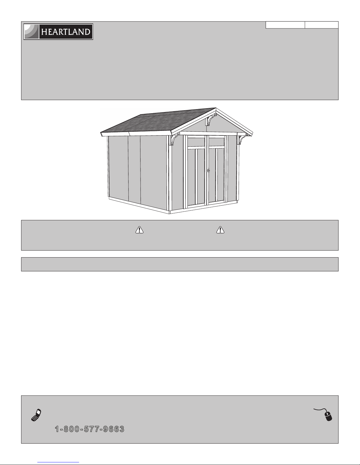
ASSEMBLY MANUAL
A Backyard Products Company
ARCHITECTURAL SERIES
PRESTWICK 8' x 10' (244 x 304,8 cm)
ACTUAL FLOOR SIZE IS: 96" x 120" (243,8 x 304,8 cm)
KEEP THIS MANUAL FOR FUTURE REFERENCE
16660
01/13/2016
IMPORTANT!
READ INSTRUCTIONS THOROUGHLY PRIOR TO BEGINNING ASSEMBLY.
BEFORE YOU BEGIN
• BUILDING RESTRICTIONS AND APPROVALS
Be sure to check with local building department and homeowners association for speci c restrictions and/ or requirements before building.
• ENGINEERED DRAWINGS
Contact our Customer Service Team if engineered drawings are needed to pull local permits.
• SURFACE PREPARATION
To ensure proper assembly you must build your shed on a level surface. Recommended methods and materials to level your shed are
listed on page 8.
• CHECK ALL PARTS
Inventory all parts listed on pages 3 - 4. Contact our Customer Service Team if any parts are missing or damaged.
• ADDITIONAL MATERIALS
You will need additional materials to complete your shed. See page 5 for required and optional materials and quantities.
- CUSTOMER SERVICE -
Call: 1- 800- 577- 9663 email: customerservice@backyardproductsllc.com
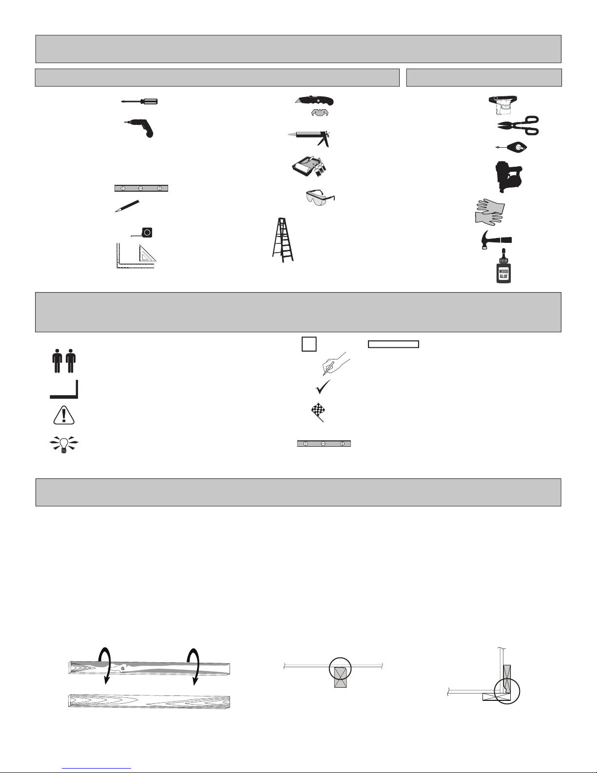
TOOLS
OptionalRequired
Phillips
Screwdriver
Drill / Driver
5/16" Drill Bit
1/8" Drill Bit
#2 Philips Drive Bit
Level
Pencil
Tape Measure
Square
or
Safety! Always use approved safety glasses during assembly.
HELPFUL REMINDER SYMBOLS
Look for these symbols for helpful reminders throughout this manual.
= Assistance Required; two or more people.
Utility Knife
Shingle Blades
Caulk Gun
Paint Tools
Safety Glasses
Ladder
x3
PLA
= Mark part with pencil.
Tool Belt/
Nail Pouch
Tin Snips
(for drip edge)
Chalk Line
Nail Gun
• gun nails
Gloves
Hammer
Wood Glue
2 x 2 x 10-3/8" (5,1 x 5,1 x 26,4 cm)
= Ensure squareness.
= Important required step or operation.
= Helpful assembly hint.
BEGIN
FINISH
= Beginning of steps for assembly or installation.
= You have nished the assembly or installation.
= Level
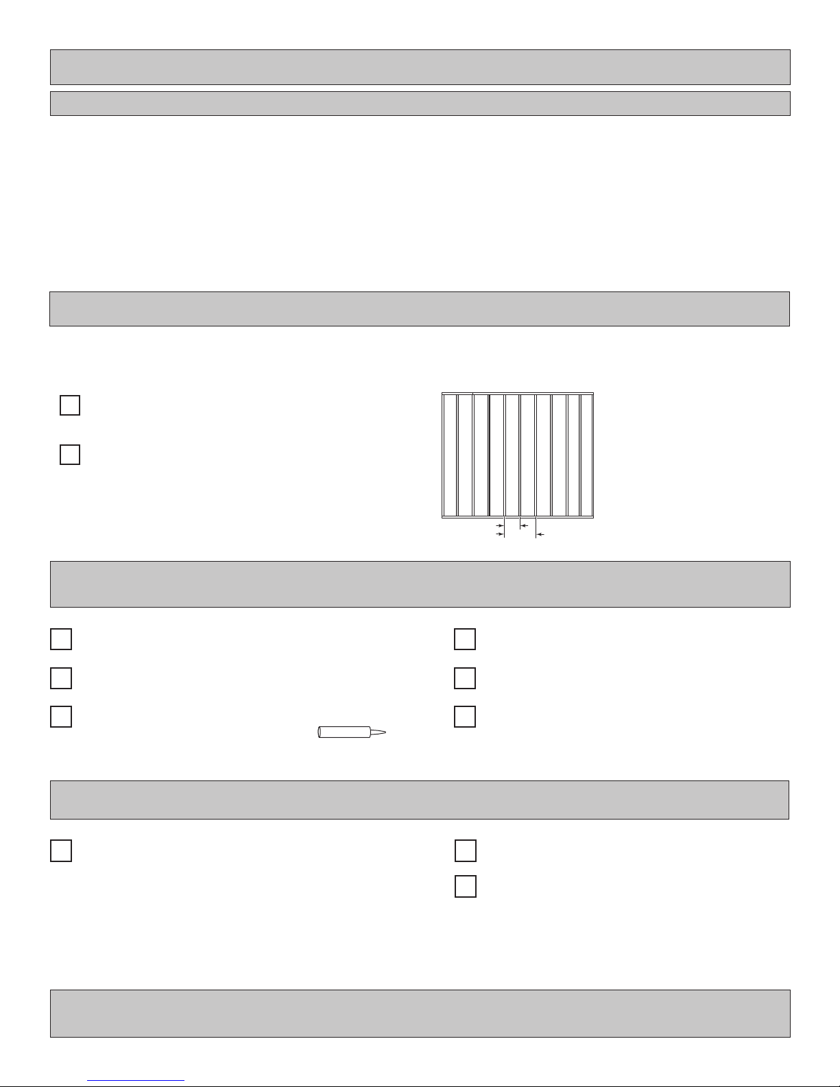
ORIENT LUMBER AND TRIM FOR BEST APPEARANCE
Framing lumber is graded for structural strength and not appearance. Exterior trim is graded for one good side.
Always install the material leaving the best edge and best surface visible. Please remember that these blemishes in no way
negatively affect the strength or integrity of our product. (See Fig. A, B, C.)
A
B C
2
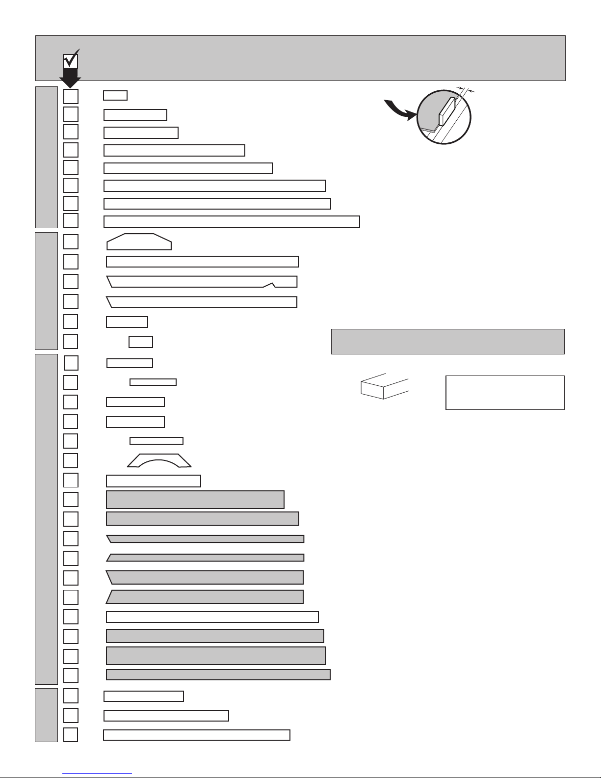
2" x 4"..............1-1/2" x 3-1/2" (3,8 x 8,9 cm)
WALLS
3/4"
PARTS LIST
INVENTORY YOUR PARTS before you begin.
We suggest sorting parts by the category they are listed in.
1 x 3 x 5" (2,5 x 7,6 x 12,7 cm) Gauge Block for 3/4" (1,9 cm) measurement
GAA
x1
x1
x1
x4
x1
x16
x3
YG
SBA
SP
QU
TM
THA
2 x 4 x 17-1/2" (2,5 x 10,2 x 44,5 cm)
2 x 4 x 21" (5,1 x 10,2 x 53,3 cm)
2 x 4 x 48" (5,1 x 10,2 x 122 cm)
2 x 4 x 56" (5,1 x 10,2 x 142,2 cm)
2 x 4 x 72" (5,1 x 10,2 x 182,9 cm)
2 x 4 x 73-1/2" (5,1 x 10,2 x 186,7 cm)
(1,9 cm)
RAFTERSDOOR
x2
x9
x1
x10
x4
x8
x4
x6
x3
x4
x2
x3
x3
x2
x2
SZ
JF
QJA
QHA
RCO
PVA
GCA
PRO
NGO
FJ
PKA
LPA
LV
6 x 24" (15,2 x 61 cm)
2 x 4 x 8-7/8" (5,1 x 10,2 x 22,5 cm)
2 x 4 x 5-7/8" (5,1 x 10,2 x 14,9 cm)
1 x 3 x 9-1/2" (2,5 x 7,6 x 24,17 cm)
2 x 2 x 10-3/8" (5,1 x 5,1 x 26,4 cm)
1 x 3 x 11-7/8" (2,5 x 7,6 x 30,2 cm)
1 x 4 x 11-7/8" (2,5 x 10,2 x 30,2 cm)
2 x 2 x 12" (5,1 x 5,1 x 30,5 cm)
2 x 4 x 14" (5,1 x 10,2 x 35,6 cm)
2 x 3 x 22-1/2" (5,1 x 7,6 x 57,1 cm)
2 x 4 x 89" (5,1 x 10,2 x 226,1 cm)
1 x 4 x 60" (2,5 x 10,2 x 152,4 cm)
2 x 4 x 59-7/8" (5,1 x 10,2 x 152,1 cm)
2 x 4 x 59-7/8" (5,1 x 10,2 x 152,1 cm)
PARTS IDENTIFICATION AND SIZES
Part identication
letters are stamped on some parts.
RS
RS
Check these locations for
part stamp.
3/8 x 5-7/8 x 47-7/8" (1 x 12,1 x 121,6 cm)
WOOD SIZE CONVERSION CHART
Nominal Board Size Actual Size
1" x 4".................3/4" x 3-1/2" (1,9 x 8,9 cm)
2" x 3"..............1-1/2" x 2-1/2" (3,8 x 6,3 cm)
1" x 3".................3/4" x 2-1/2" (3,8 x 6,3 cm)
x2
TRIM
x1
x1
x2
x2
x1
WR
x2
x2
x8
x2
x2
x2
GI
FDA
OO
19/32 x 2-1/2 x 23" (1,5 x 6,3 x 58,4 cm)
3/8 x 4-3/4 x 61-1/2" (1 x 12,1 x 156,2 cm)
3/8 x 2-1/2 x 61" (1 x 6,4 x 154,9 cm)
3/8 x 2-1/2 x 61" (1 x 6,4 x 154,9 cm)
3/8 x 4-3/4 x 61" (1 x 12,1 x 154,9 cm)
3/8 x 4-3/4 x 61" (1 x 12,1 x 154,9 cm)
19/32 x 2-1/2 x 63" (1,5 x 6,4 x 160 cm)
3/8 x 4-3/4 x 72" (1 x 12,1 x 182,9 cm)
3/8 x 5-7/8 x 73-5/8" (1 x 14,9 x 187,6 cm)
3/8 x 2-13/16 x 73-7/8" (1 x 7,1 x 187,6 cm)
19/32 x 2-1/2 x 55-1/8" (1,5 x 6,3 x 140 cm)
1-1/4 x 2-1/2 x 69" (3,2 x 6,3 x 175,3 cm)
3
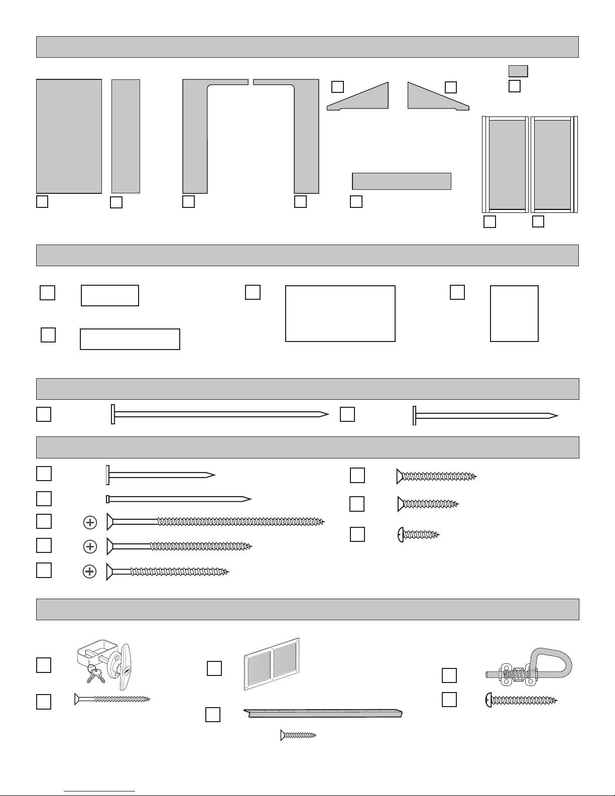
WALL PANELS, OVERHANG, SOFFIT & DOORS
NOTE: Panel parts are not stamped.
x6
3/8 x 48 x 76"
(1 x 121,9 x 193 cm)
Roof panels are 7/16" (1,1 cm) thick.
x2
3/8 x 23-7/8 x 76"
(1 x 60,6 x 193 cm)
3/8 x 48 x 76"
(1 x 121,9 x 193 cm)
x2
7/16 x 11-7/8 x 48"
(1,1 x 30,2 x 121,9 cm)
x2
7/16 x 11-7/8 x 84"
(1,1 x 30,2 x 213,4 cm)
x1
x2
3/8 x 24-3/8 x 48"
(1 x 61,9 x 121,9 cm)
x1
3/8 x 48 x 76"
(1 x 121,9 x 193 cm)
ROOF PANELS
x2
7/16 x 48 x 96"
(1,1 x 121,9 x 243,8 cm)
3/8 x 24-3/8 x 48"
(1 x 61,9 x 121,9 cm)
3/8 x 11-7/8 x 58-1/4"
x2
(1 x 30,2 x 148 cm)
x2
LEFT DOOR
NOTE: Panel par ts are not stamped.
x2
3/8 x 3-1/2 x 5-7/8"
(1 x 8,9 x 14,9 cm)
x1
RIGHT DOOR
x1
x2
7/16 x 36 x 48"
(1,1 x 91,4 x 121,9 cm)
x1
x125
x305
x96
x12
x42
T-Handle
x1
BOXES
3" (7,6 cm)
1-1/2" (3,8 cm)
2" (5,1 cm)
3" (7,6 cm)
2" (5,0 cm)
1-5/8" (4,1 cm)
DOOR & WINDOW HARDWARE / VENT
NAIL BOXES
BOXES
x3
FASTENER/HARDWARE BAG
x8
x70
x12
Vent
x2
2" (5,1 cm)
1" (2,5 cm)
3/4" (1,9 cm)
1/2" (1,3 cm)
Spring-Bolt
x2
x2
1-1/2" (3,8 cm)
(2 screws in each package)
x1
56" Metal Threshold
Bagged seperately / special coating
3/4" (1,9 cm) x18
4
x8
1" (2,5 cm)
(4 screws in each package)
ADDITIONAL MATERIALS
FOUNDATION OR FLOOR MATERIALS
• This shed does not include any oor or leveling materials. Use our optional oor kit with building instructions and nails included.
• See the FLOOR LEVELING section on page 8 for recommended methods and suggested materials to properly level your oor,
as this will vary depending on your specic site.
• If you choose to install your kit on a concrete slab refer to page 6.
• If you choose to build your own wood oor foundation refer to page 7.
REINFORCED WOOD FLOOR FRAME (OPTIONAL)
IMPORTANT! Depending on your specic use you may want to construct a heavy duty oor frame by adding additional oor joists
(shown below as shaded). Below is a list of additional materials (not included):
2 x 4 x 8' (5 x 10 x 244 cm) Treated Lumber
x5
Cut to (3) 2 x 4 x 93" (5 x 10 x 236 cm)
ea. 3" (7,6 cm) Hot Dipped Galvanized Nails
x20
Optional 12" (30,5 cm) spacing
Standard 16" (40,7 cm) spacing
COMPLETING YOUR SHED
You will need these additional materials:
3-TAB SHINGLES ............................. 5 Bundles
PAINT FOR SIDING .......................... 2 Gallons
Use 100% acrylic latex exterior paint. (2) coats recommended.
CAULK ................................................. 2 Tubes
Use acrylic latex exterior caulk that is paintable.
1" GALVANIZED ROOFING NAILS.... 3 Lbs
For shingles.
PAINT FOR TRIM ........................... 2 Quarts
Use 100% acrylic latex exterior paint.
WOOD GLUE ....................... Exterior Rated
OPTIONAL MATERIALS
DRIP EDGE ..................... 43 Feet #15 ROOFING FELT
To cover 110 Sq. Ft. of roof area.
1" GALVANIZED ROOFING NAILS.........1/4 Lb
For roong felt.
REFER TO THE BACK OF THIS MANUAL AND THE MANUFACTURER’S INSTRUCTIONS
FOR INSTALLATION OF SHINGLES, DRIP EDGE AND FELT.
5
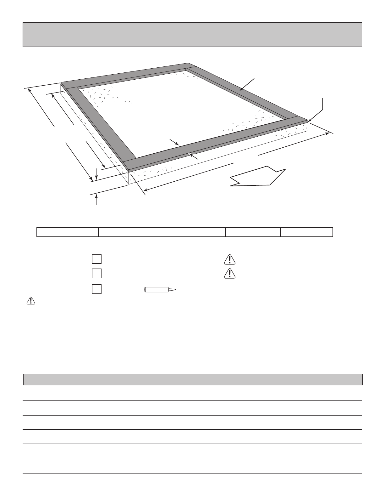
CONCRETE FOUNDATION
D
O
O
R
If you choose to install your kit on a concrete slab refer to the diagram below.
Treated Sill Plate
Caulk between sill plate
and concrete.
B
8' x 10' (243,8 x 304,8 cm)
Allow new concrete slabs to cure for at least seven (7) days.
C
4"
(10,2 cm)
Requires:
8' x 10' (235 x 304,8 cm)
ACTUAL FLOOR SIZE IS: 96" x 120" (243,8 x 304,8 cm)
x2
2 x 4 x 8' (5,1 x 10,2 x 243,8 cm)
x2
2 x 4 x 10' (5,1 x 10,2 x 305 cm)
Caulk
x2
3-1/2"
(8,9 cm)
A B CActual Floor SizeBuilding Size
96" (243,8 cm)
A
120" (304,8 cm)
MUST be treated lumber.
MUST be treated lumber.
113" (287 cm)
• A treated 2 x 4" (5,1 x 10,2 cm) sill plate is required when installing your shed on concrete.
• Use a high quality exterior grade caulk beneath all sill plates.
• Fasten 2 x 4" (5,1 x 10,2 cm) sill plates to slab using approved concrete anchors (fasteners not included).
• Check local code for concrete foundation requirements.
NOTES
6
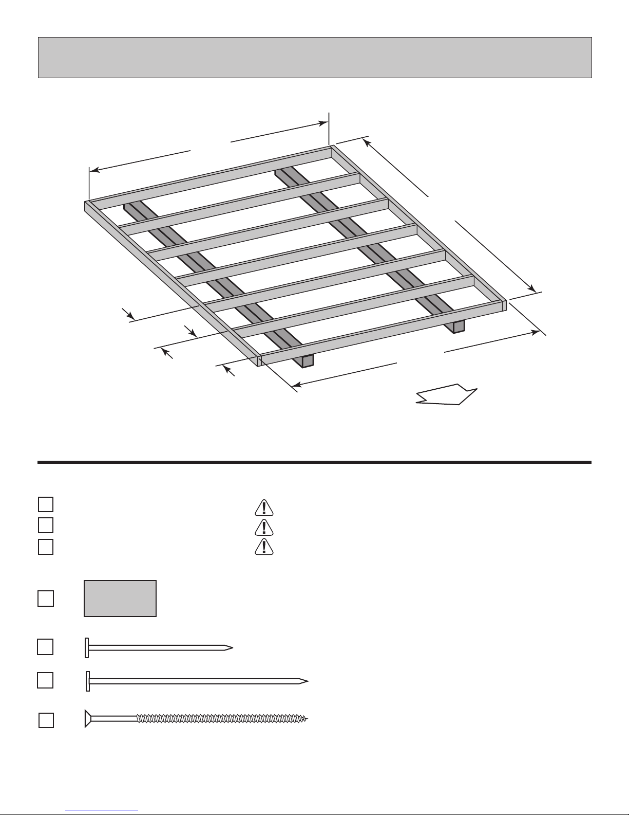
BUILD YOUR OWN WOOD FLOOR OPTION
(Materials not included.)
93"
(236,2 cm)
16"
(40,6 cm)
16"
(40,6 cm)
(243,8 cm)
120"
(304,8 cm)
96"
MATERIAL REQUIRED
x2
2" x 4" x 10' (5,1 x 10,2 x 304,8 cm)
2" x 4" x 8' (5,1 x 10,2 x 243,8 cm)
x7
4" x 4" x 10' (10,2 x 10,2 x 304,8 cm)
x2
x3
x1
2" (5,1 cm)
x28
5/8" x 48" x 96" (1,6 x 121,9 x 243,8 cm)
3" (7,6 cm)
R
O
O
D
MUST be treated lumber
MUST be treated lumber
MUST be treated lumber
1 lb. of 2" (5,1 cm) Hot Dipped Galvanized Box-Type Nails
40 Nails - 3" (7,6 cm) Hot Dipped Galvanized Box-Type Nails
x28
3" (7,6 cm)
Screws for Frame to 4"x 4"
Minimum 3" screws / exterior grade.
7
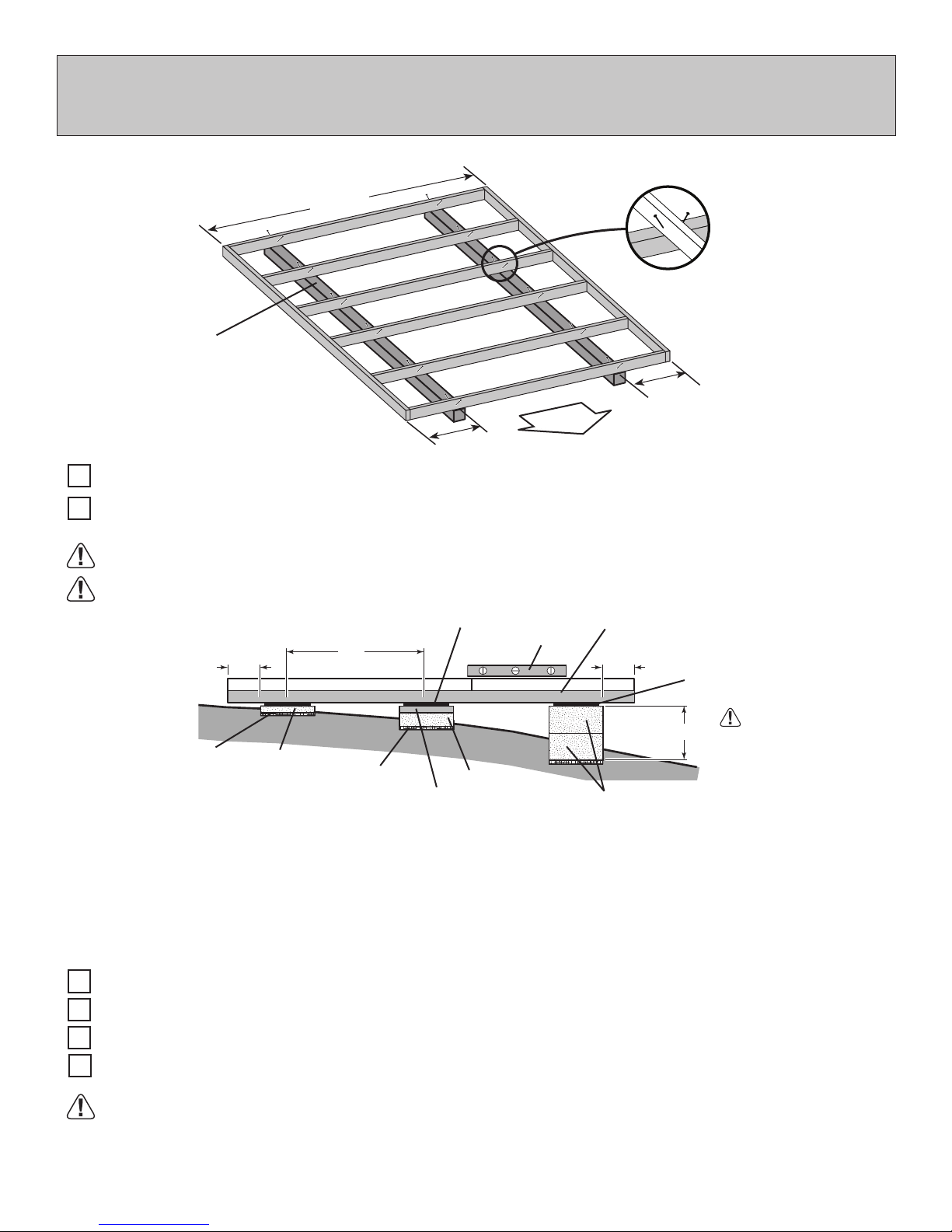
OPTIONAL WOOD FRAME FLOOR LEVELING OPTIONS
There are multiple ways to level your oor frame. Our recommended leveling method is shown below.
Leveling materials are not included in this kit.
PREFERRED METHOD - 4x4 TREATED RUNNERS (Typical for 8' x 10' Kit)
96"
(243,8 cm)
• 3" Screw angled into 4x4.
• (2) at each point frame
and 4x4 touch.
Runners are generally 12"
(30,5 cm) from ends of oor
4x4 Runners
(not included).
MATERIAL REQUIRED
4" x 4" x 10' (10,2 x 10,2 x 304,8 cm) Treated Lumber
x2
12"
(30,5 cm)
Fasteners for Frame to 4"x 4".
(3" Screws shown as one option.) Minimum (24) 3" screws / exterior grade.
D
O
O
R
frame and under seams.
12"
(30,5 cm)
Measurements to
centers of 4x4's.
Use only wood treated for ground contact and fasteners approved for use with treated wood.
Always support frame seams.
Shingle
Level
4" Block
2x4 Treated Lumber
4x4 Runner
12"
8" Block
Shingle
Do not exceed 16".
12"
Gravel
LEVELING METHODS
Maximum between leveling
material locations.
48"
2" Block
Gravel
• Level under 4x4 runners only.
• Locate leveling material 12" from ends of runners and no more than 48" apart.
• Asphalt shingles should be used between 4x4 runners and blocks or treated lumber. Never use
shingles in direct contact with ground.
• For best results and aiding in water drainage use gravel under each concrete block.
LEVELING MATERIALS
Gravel
Solid Masonry Blocks in 1", 2", 4" or 8" thickness
2x4 Treated Lumber
Asphalt Shingles
Leveling higher than 16" not recommended.
CONCRETE
• If you are building your shed on a concrete foundation see the following page.
8
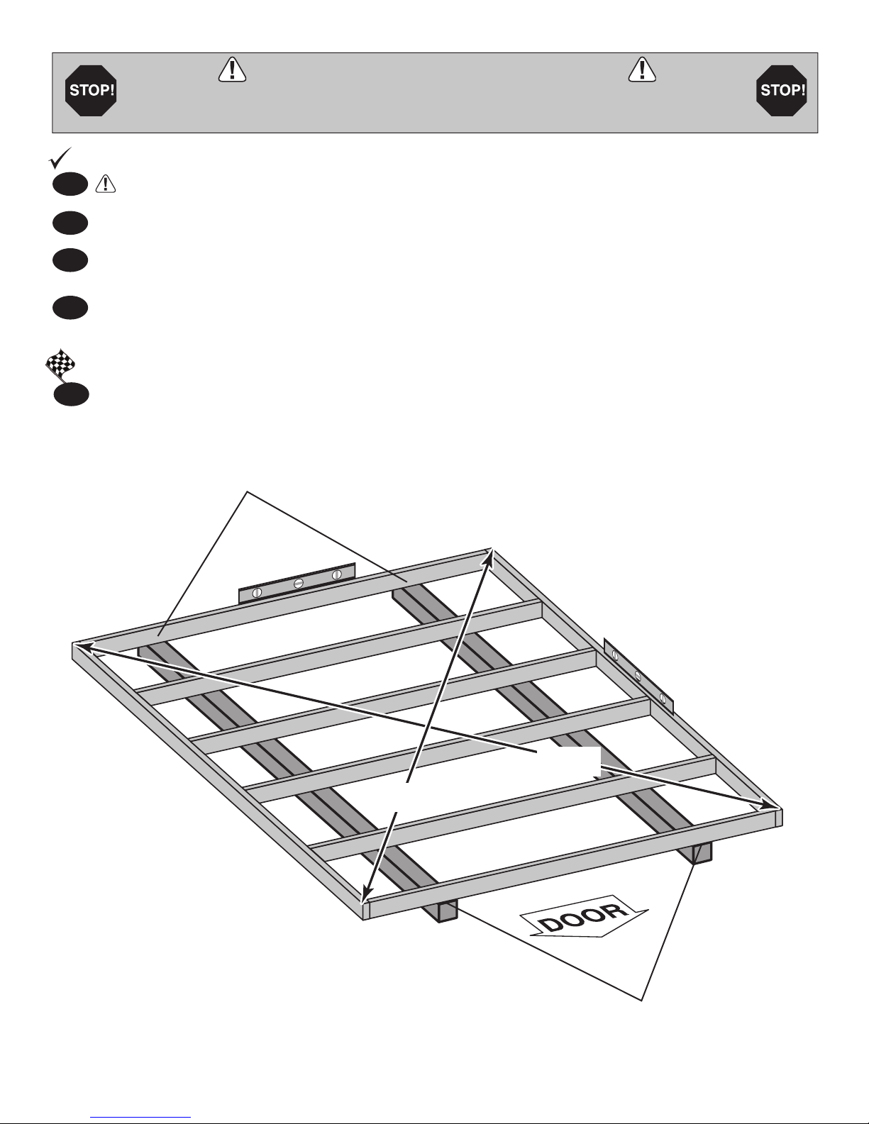
LEVEL AND SQUARE FLOOR FRAME
Before attaching oor decking, it is important to level and square the oor frame.
A level and square oor frame is required to correctly construct your shed.
BEGIN
1
See page 8 for the preferred oor leveling method.
2
Use level and check the frame is level before applying oor panels.
Check for frame squareness by measuring diagonally across corners. If the measurements are the
3
same, the frame is square. The diagonal measurement will be approximately 150-5/16" (383,4 cm).
4
When the frame is level and square secure one side of frame to the 4x4 runners using one fastener at
ends of each runner. At the opposite end of the frame, secure the frame to 4x4 runners with one fastener
at ends of each runner making sure the frame remains square (Fig. A).
FINISH
Once the oor frame is level and square fasten the frame at each point the frame contacts the 4x4
5
runners.
Second, secure at ends
with one fastener.
Fig. A
150-15/16"
(383,4 cm)
150-15/16"
(383,4 cm)
First, secure at ends
with one fastener.
9
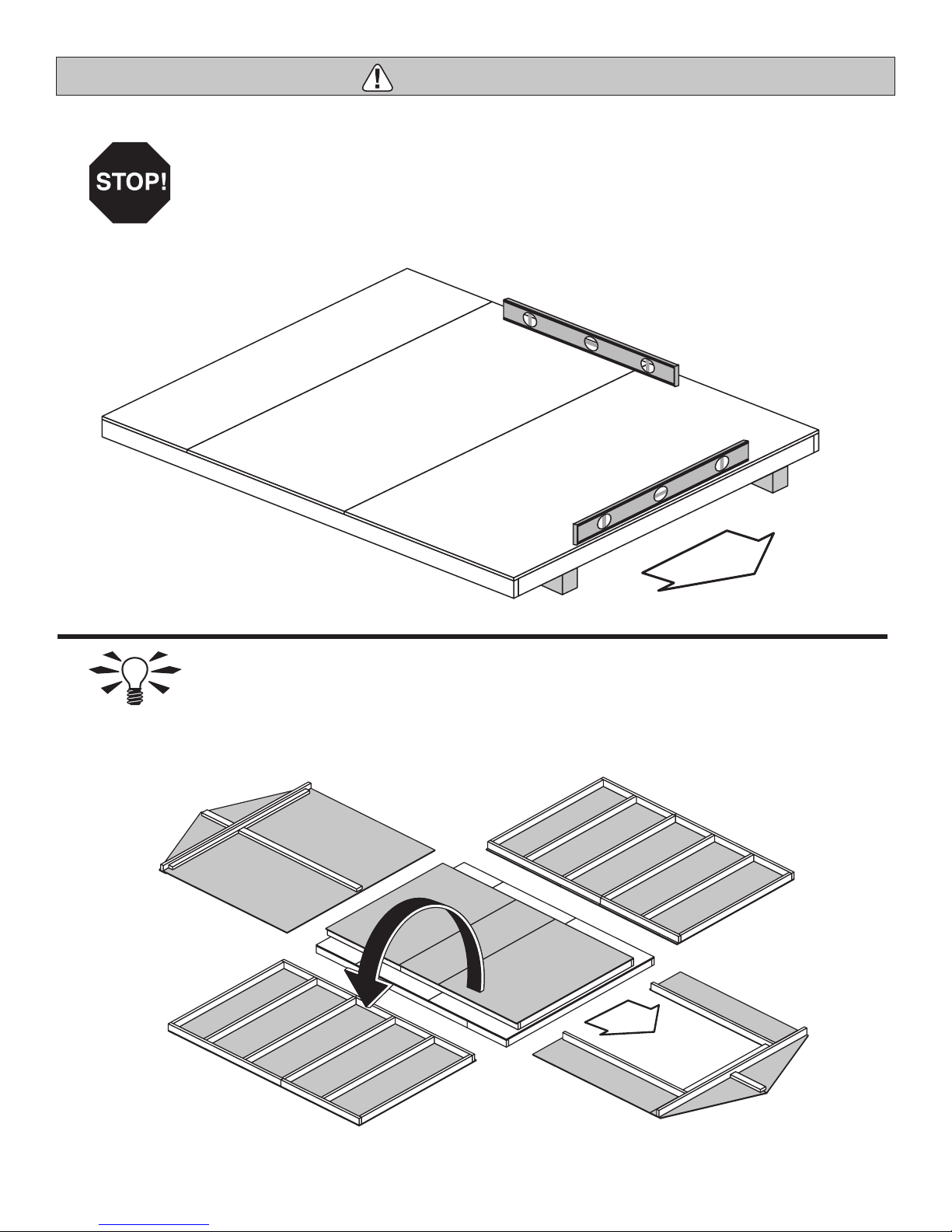
IMP ORTANT!
IMPORTANT!
Check the oor frame is level after installing oor panels. Re-level if needed.
HINT:
BACK WALL
DOOR
• The oor should be used as a stable work surface for wall construction.
• Organize your assembly procedure during the build process
to avoid over-handling of the walls.
EAVE WALL
DOOR
EAVE WALL
FRONT WALL
10
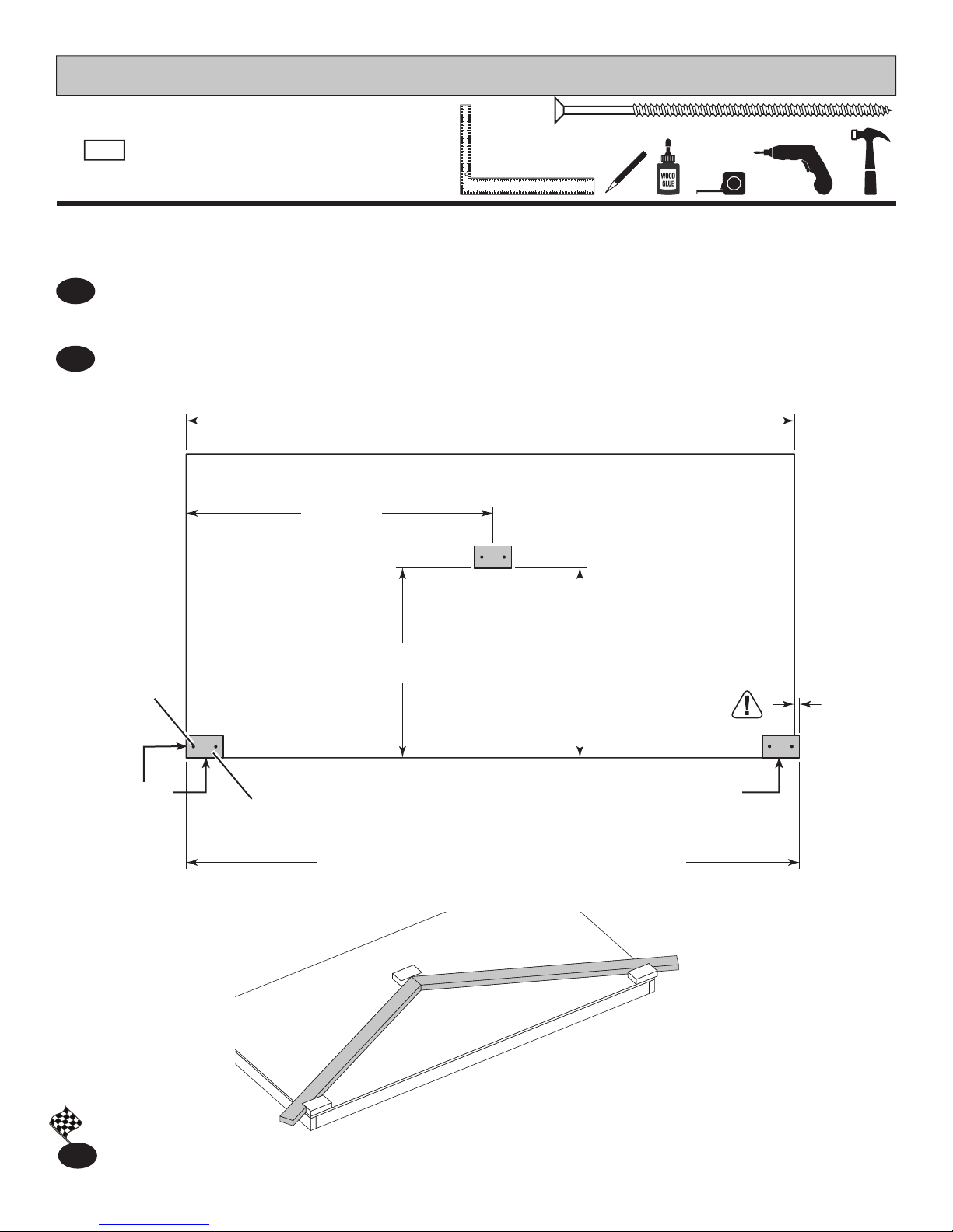
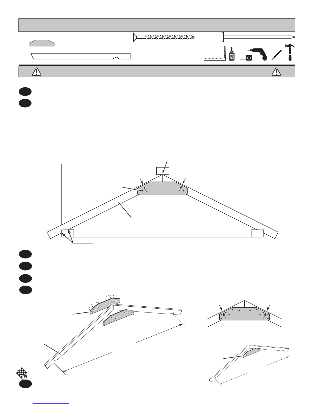
RAFTER ASSEMBLY
PARTS REQUIRED:
x3
2 x 4 x 5-7/8" (5,1 x 10,2 x 14,9 cm)
PVA
x6
3" (7,6 cm)
It is very important to assemble your rafters using the following method for an even and at roof.
You will build a rafter jig using the oor and three PVA parts as shown.
BEGIN
¸
Secure one PVA ush to the oor deck using two 3" screws.
1
Measure over 96-3/4" and install a second PVA ush to the oor deck. PWA will overhang the oor.
Secure using two 3" screws.
Measure over 48-1/8" and up 22-1/4" from the oor edges and secure the third PWA using two 3" screws.
2
Check this PVA is 22-1/4" at both ends for squareness.
96"
(243,8 cm)
Floor Width
Fig. A
48-1/8"
(122,2 cm)
(2) 3" (7,6 cm)
Screws
in each PWA
Flush Flush
Fig. B
PVA x3
(56,5 cm)
96-3/4"
(245,7 cm)
22-1/4"
22-1/4"
(56,5 cm)
IMPORTANT MEASUREMENT !!
There will be an
overhang on
this end.
3/4"
(1,9 cm)
FINISH
3
You have nished rafter jig. Proceed to assemble your rafters.
11
RAFTER ASSEMBLY
¸
FINISH
PARTS REQUIRED:
x9
6 x 24" (15,2 x 61 cm)
x10
QJA
2 x 4 x 59-7/8" (5,1 x 10,2 x 152,1 cm)
BEGIN
Place two rafters QJA into the jig as shown.
1
Keep QJA rm against outside PVA's as shown (Fig.A) and push rafters tight to the middle PVA. Rafters should
2
touch at tips (Fig. A).
Apply glue to rafters where gusset will attach (Fig. B).
Place gusset onto QJA holding a 1/4" gap from edge (Fig. C) and keeping rafters rm as instructed. Secure
gusset using one 1-5/8" screw into each rafter. HINT: These screws will help hold the measurements when you
nail on gussets.
Use ten 2" nails to nish securing the gusset to the rafters to pattern shown in Fig. C.
Fig. A
OSB OR WOOD GRAIN
YOU WILL BUILD 5 RAFTERS - ONE OF WHICH WILL HAVE ONLY 1 GUSSET
1-5/8" (4,1 cm)
Screw
x 10
1/4" (1,9 cm)
GAP
1-5/8" (4,1 cm)
Keep rafters tips rmly against
1/4" (1,9 cm)
GAP
x 108
2" (5,1 cm)
PVA when securing gusset.
QJA x2
Keep rafters rmly against PVA at both ends when securing gusset.
Flip rafters over and attach a second gusset using glue and (12) 2" nails. No need to use jig for this step.
3
Repeat steps 1 - 3 to assemble three more rafters with two gussets.
4
Repeat steps 1 - 2 to assemble one rafter with only one gusset (Fig. D).
5
6
Remove PVA's from oor.
Fig. B
Glue where
gusset installs
QJA x2
96-3/4"
(245,7 cm)
FINISH
You have nished assembling your rafters.
7
1/4" (1,9 cm)
GAP
Glue where
gusset installs
Fig. C
Fig. D
1/4" (1,9 cm)
GAP
96-3/4"
(245,7 cm)
12
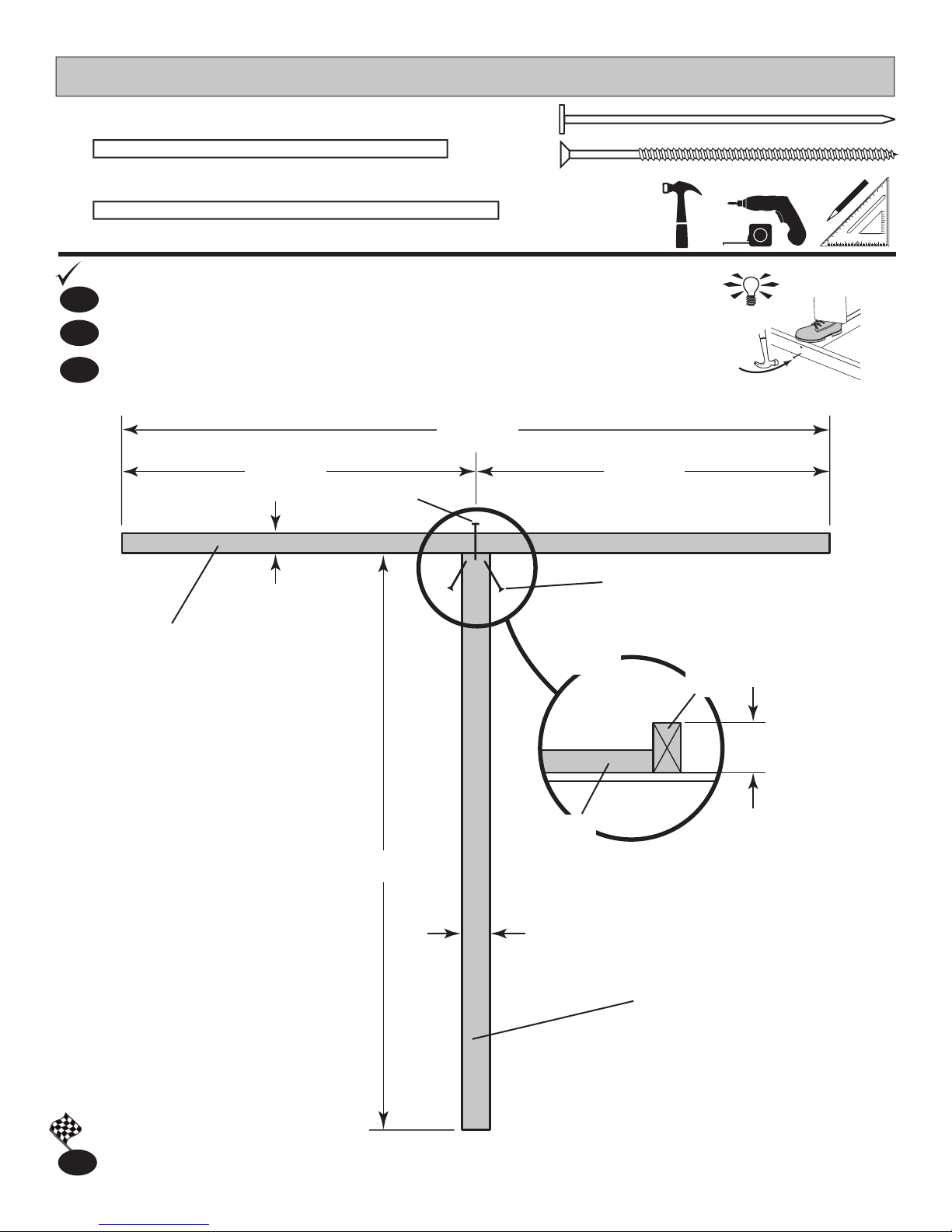
BACK WALL FRAME
PARTS REQUIRED:
x1
x1
THA
2 x 4 x 73-1/2" (5,1 x 10,2 x 186,7 cm)
SZ
2 x 4 x 89" (5,1 x 10,2 x 226,1 cm)
BEGIN
1
Orient parts on oor as shown (Fig. A). Measure and mark.
2
Fasten SZ to THA with one 3" nail as shown.
3
Toe-screw up through THA into SZ with two 3" screws.
44-1/ 2"
(113 c m)
x1
3" (7,6 cm)
x2
3" (7,6 cm)
HINT:
89"
(2 2 6 ,1 cm)
44-1/ 2"
(113 c m)
3" (7,6 cm)
Nail
SZ
1-1/2"
(3,8 c m)
(2) 3" (7,6 cm)
Screws
Fig. A
SZ
3-1/2 "
(8,9 cm)
THA
73 -1/2"
(186,7 cm)
3-1/2 "
(8,9 cm)
THA
FINISH
You have nished building your back wall frame.
4
13
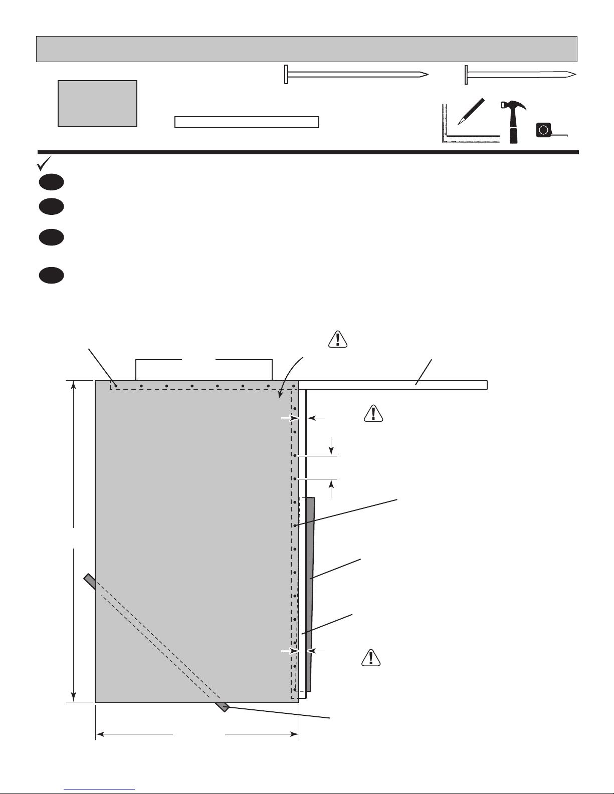
BACK WALL PANELS
PARTS REQUIRED:
x1
3/8 x 48 x 76"
(1 x 121,9 x 193 cm)
BEGIN
Carefully ip the back wall frame over.
1
2
Place SP on at under THA for temporary support as shown.
Place 48" x 76" panel on frame with primed side facing up.
3
Use SP on edge to support the panel as shown.
Hold panel ush against top plate SZ and keep 1-3/4" measurement along middle stud.
4
Nail using 1-1/2" and 2" nails spaced 6" apart.
2" (5,1 cm)
Nails
x2
x8
SP
Temporary Support
2 x 4 x 48" (5,1 x 10,2 x 122 cm)
Flush
2" (5,1 cm)
Primed side UP
x21
1-1/2" (3,8 cm)
SZ
76"
(193 cm)
1-3/4
(4,4 cm)
6"
(15,2cm)
1-3/4
(4,4 cm)
1-1/2" (3,8 cm)
Nails
SP (on at)
Temporary Support
THA
For squareness maintain 1-3/4"
measurement along panel edge.
48"
(121,9 cm)
SP (on edge)
Temporary Support
14

BACK WALL PANELS
PARTS REQUIRED:
x1
3/8 x 48 x 76"
(1 x 121,9 x 193 cm)
5
Place panel on frame as shown with primed side facing up and ush to installed panel.
x1
SP
Temporary Support
2 x 4 x 48" (5,1 x 10,2 x 122 cm)
x8
2" (5,1 cm)
Use SP to support frame and panel while nailing.
Hold panel tight to the installed panel and tight against top plate.
6
Nail using 1-1/2" and 2" nails spaced 6" apart.
FINISH
You have nished installing your back wall panels.
7
For squareness hold panel tight
against left panel and top plate.
Primed side UP
x21
1-1/2" (3,8 cm)
2" (5,1 cm)
Nails
1-1/2" (3,8 cm)
Nails
To draw panels tight
angle nail at seam.
SP (on edge)
Temporary Support
6"
(15,2cm)
76"
(193 cm)
48"
(121,9 cm)
15
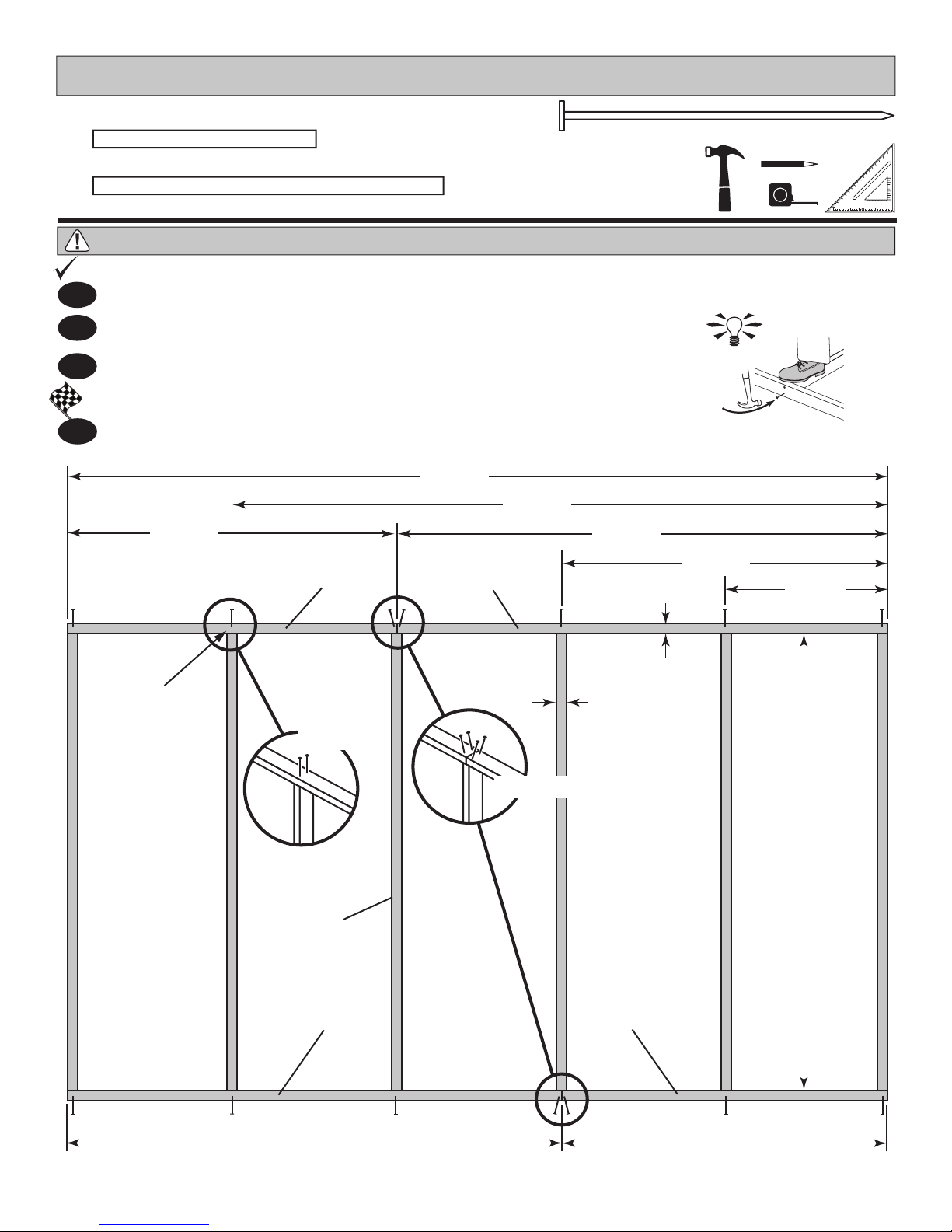
EAVE SIDE WALL FRAMING
PARTS REQUIRED:
x4
x16
SP
2 x 4 x 48" (5,1 x 10,2 x 122 cm)
TM
2 x 4 x 72" (5,1 x 10,2 x 182,9 cm)
x56
IMPORTANT! YOU WILL BUILD TWO IDENTICAL EAVE SIDE WALLS.
BEGIN
Orient parts on edge on oor. Measure and mark.
1
2
Use two 3" nails at each mark.
3
Repeat STEPS 1 - 2 to build the second eave wall frame.
FINISH
4
You have nished building your eave wall frames.
120"
48"
(121,9 cm)
SP
(304,8 cm)
TM
96"
(24 3, 8 c m)
(182,9 cm)
3" (7,6 cm)
HINT:
72"
48"
(121,9 cm)
24"
(61 cm)
Center on
marks.
3" (7,6 cm)
Nails
TM x6
TM
1-1/2"
(3,8 c m)
1-1/2"
(3,8 c m)
TOENAILING
72"
(182,9 cm)
SP
72"
(182,9 cm)
48"
(121,9 cm)
16
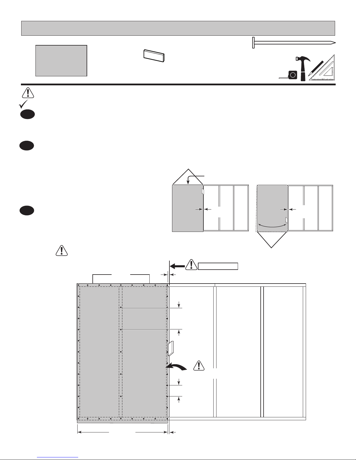
EAVE SIDE WALL PANELS
PARTS REQUIRED:
GAA
x45
3/4"
x1
3/8 x 48 x 76" (1 x 121,9 x 193 cm)
Ensure your wall frame is square by installing one panel and squaring frame.
BEGIN
1
Place a 48 x 76" panel onto wall frame with primed side up as shown.
Use the GAA gauge block to mark the 3/4" side measurement on the wall stud.
Keep panel ush along top of frame. Secure panel with two 2" nails in the corners (Fig. A).
2
Move to the opposite end. Using the long edge
of the panel as a lever, move the panel sideto-side until you have a 3/4" measurement on
the wall stud. Secure corner with two 2" nails
(Fig. B).
GAUGE BLOCK
2 Nails
Flush
Fig. A
2" (5,1 cm)
Fig. B
3
Nail the panel using 2" nails 6" apart
on edges and 12" apart inside panel.
For squareness maintain Flush and
3/4" measurement along panel edge.
Flush
3/4"
(1,9 cm)
12"
(30,5 cm)
3/4" Gauge
Block
Primed side UP
3/4"
(1,9 cm)
BEGIN HERE
3/4"
(1,9 cm)
2 Nails
48"
(121,9 cm)
6"
(15,2 cm)
3/4"
(1,9 cm)
17
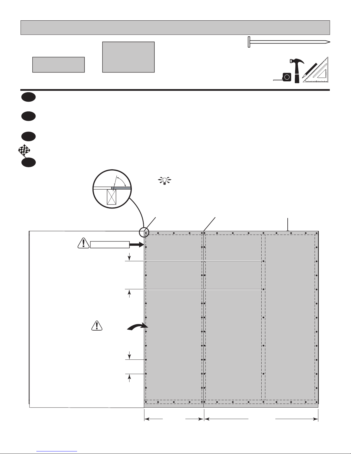
EAVE SIDE WALL PANELS
PARTS REQUIRED:
3/8 x 23-7/8 x 76"
(1 x 60,6 x 193 cm)
4
Place 23-7/8" x 76" panel on frame as shown with primed side facing up ush with rst
panel. Nail using 2" nails 6" apart on edges and 12" apart inside panel.
Place 48" x 76" panel on frame as shown with primed side facing up ush with 23-7/8"
5
panel. Nail using 2" nails 6" apart on edges and 12" apart inside panel.
Repeat STEPS 1 - 5 to install second eave side wall panels.
6
FINISH
7
You have nished building your eave walls.
x1x1
3/8 x 48 x 76"
(1 x 121,9 x 193 cm)
To draw panels tight
at seams angle nail.
x77
2" (5,1 cm)
BEGIN HERE
(30,5 cm)
Primed side UP
(15,2 cm)
Flush Flush Flush
12"
6"
23 -7/ 8"
(60,6 cm)
18
48"
(121,9 cm)
 Loading...