

Heartland 16657-NG Assembly Manual
STOP!
STOP!
16657-NG
Call Us First!
DO NOT RETURN TO STORE.
For immediate help with assembly or product information
call our toll free number:
1-800-577-9663
or email:
customerservice@backyardproductsllc.com
Our staff is ready to provide assistance
April through October M-F 8:00 AM to 4:30 PM EST
Saturday 8:30 AM to 4:30 PM EST
November through March M - F 8:00 AM to 5:00 PM EST

(This page intentionally left blank.)
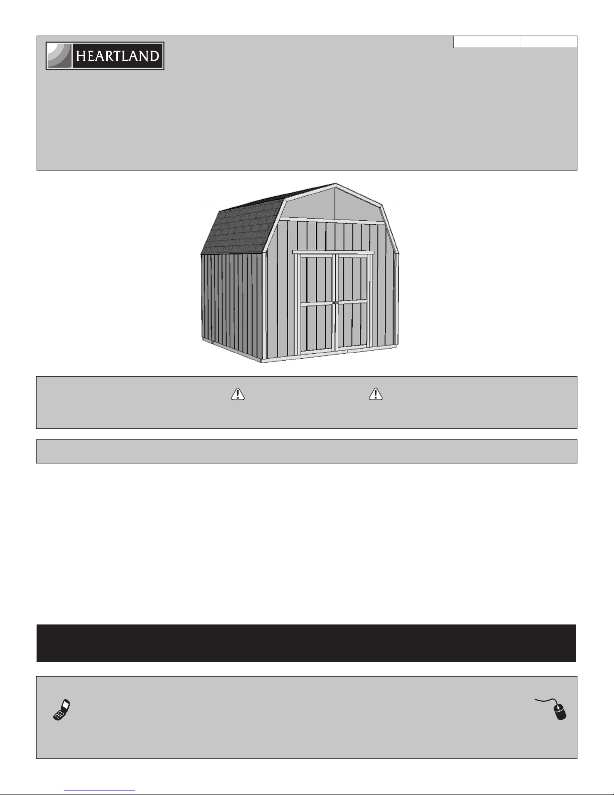
ASSEMBLY MANUAL
A Backyard Products Company
VALUE SERIES
RAINIER 10' x 10' (305 x 305 cm)
ACTUAL FLOOR SIZE IS 120 x 116-5/8" (305 x 296,2 cm)
KEEP THIS MANUAL FOR FUTURE REFERENCE
16657-NG
10/13/2017
IMPORTANT!
READ INSTRUCTIONS THOROUGHLY PRIOR TO BEGINNING ASSEMBLY.
BEFORE YOU BEGIN
•BUILDINGRESTRICTIONSANDAPPROVALS
Be sure to check with local building department and homeowners association for specic restrictions and/ or requirements before building.
•ENGINEEREDDRAWINGS
Contact our Customer Service Team if engineered drawings are needed to pull local permits.
•SURFACEPREPARATION
To ensure proper assembly you must build your shed on a level surface. Recommended methods and materials to level your shed are
listed on page 8.
•CHECKALLPARTS
Inventory all parts listed on pages 4 - 6. Contact our Customer Service Team if any parts are missing or damaged.
· ADDITIONAL MATERIALS
You will need additional materials to complete your shed. See page 3 for required and optional materials and quantities.
Call: 1-800-577-9663 email: customerservice@backyardproductsllc.com
- CUSTOMER SERVICE -
TOOLS
BEGIN
OptionalRequired
q Phillips
Screwdriver
q Drill Driver
q 3/8" Drill Bit
q #2 Philips Drive Bit
q Hammer
q Level
q Pencil
q Tape Measure
q Square
Safety! Always use approved safety glasses during assembly.
HELPFUL REMINDER SYMBOLS
Look for these symbols for helpful reminders throughout this manual.
= Assistance Required; two or more people.
= Ensure squareness.
= Important required step or operation.
= Helpful assembly hint.
q Utility Knife
q Shingle Blades
q Caulk Gun
q Paint Tools
q Safety Glasses
q Ladder
FINISH
q Tool Belt/
Nail Pouch
q Tin Snips
(for drip edge)
q Chalk Line
q Nail Gun
• gun nails
q Gloves
= Mark part with pencil.
= Beginning of steps for assembly or installation.
= You have nished the assembly or installation.
= Level
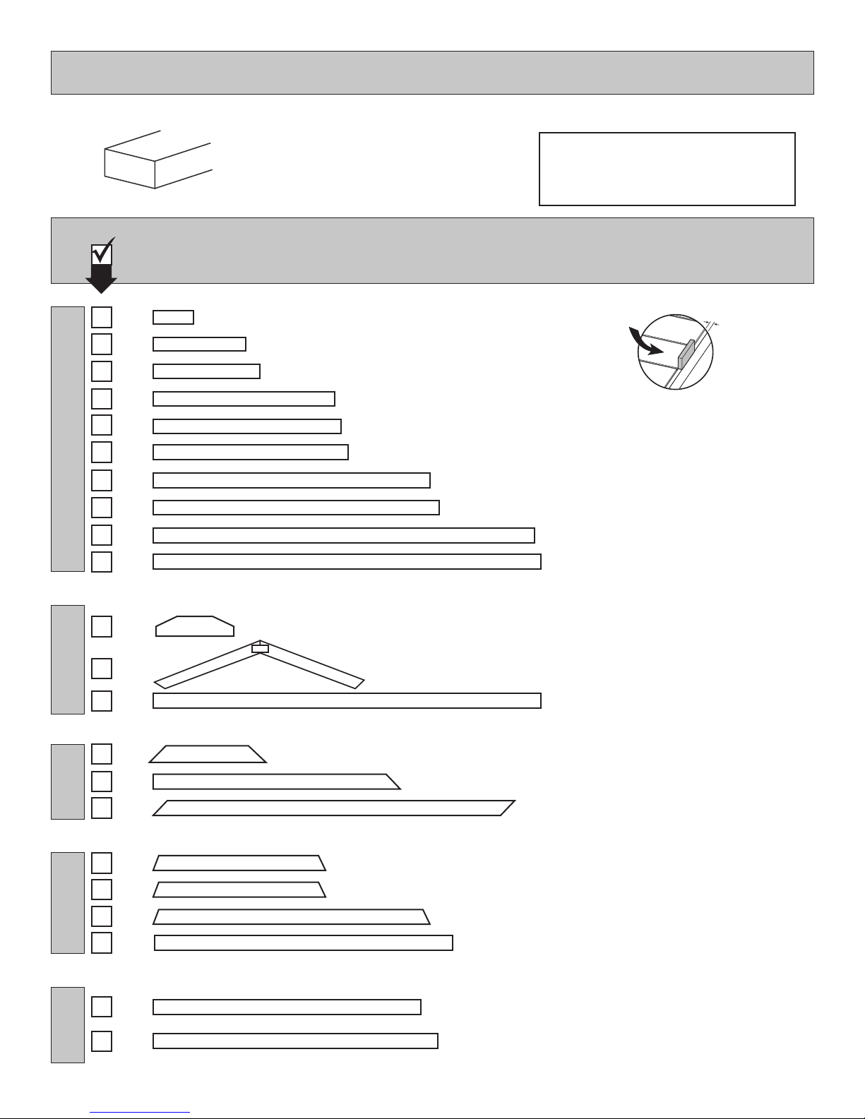
ORIENT LUMBER AND TRIM FOR BEST APPEARANCE
Framing lumber is graded for structural strength and not appearance. Exterior trim is graded for one good side.
Always install the material leaving the best edge and best surface visible. Please remember that these blemishes in no way
negatively affect the strength or integrity of our product. (See Fig. A, B, C.)
A
B C
2
ADDITIONAL MATERIALS FOR BUILDING YOUR SHED
OPTIONAL MATERIALS
FOUNDATION OR FLOOR MATERIALS
DRIP EDGE ..................... 30 Feet #15 ROOFING FELT
To cover 145 Sq. Ft. of roof area.
1" GALVANIZED ROOFING NAILS.........1/4 Lb
For roofing felt.
REFER TO THE BACK OF THIS MANUAL AND THE MANUFACTURER’S INSTRUCTIONS
FOR INSTALLATION OF SHINGLES, DRIP EDGE AND FELT.
• This shed kit does not include a wood floor frame or floor panels. See pages 10 through 14 for suggested floor construction.
• It does not include ANY leveling materials.
•
•
See the FLOOR LEVELING section on page 8 for recommended methods
See the CONCRETE FOUNDATION section on page 9 for recommended methods to build your shed on a poured concrete slab.
and suggested materials to properly level your
fl oor, as this will vary depending on your specifi c site.
3-TAB SHINGLES ............................ 6 Bundles
PAINT FOR SIDING .......................... 2 Gallons
Use 100% acrylic latex exterior paint. (2) coats recommended.
CAULK ................................................. 3 Tubes
Use acrylic latex exterior caulk that is paintable.
1" GALVANIZED ROOFING NAILS.... 3 Lbs
For shingles.
PAINT FOR TRIM .............................1 Quart
Use 100% acrylic latex exterior paint.
WOOD GLUE ....................... Exterior Rated
REINFORCED WOOD FLOOR FRAME (OPTIONAL)
WOOD FLOOR FRAME (NOT INCLUDED)
IMPORTANT!
x2
x8
2 x 4 x 10' (5 x 10 x 305 cm) Treated Lumber
x11
2 x 4 x 10' (5 x 10 x 305 cm) Treated Lumber
x9
Cut to: 2 x 4 x 117" (5 x 10 x 297,1 cm)
2 x 4 x 117" (5 x 10 x 297,1 cm)
x2
2 x 4 x 116-5/8" (5 x 10 x 296,2 cm)
ea. 10D 3" (7,6 cm) Hot Dipped Galvanized Nails
Optional 12" (30,5 cm) spacing
FLOOR PANELS (NOT INCLUDED)
x178
x4
MATERIAL LIST: CUT LIST:
MATERIAL LIST: CUT LIST:
5/8 x 23-7/8 x 96" (1,6 x 60,4 x 244 cm)
x1
5/8 x 20-5/8 x 96" (1,6 x 52,4 x 244 cm)
x1
5/8 x 20-5/8 x 23-7/8" (1,6 x 52,4 x 60,4 cm)
x1
Depending on your specific use, you may want to construct a heavy
duty floor frame by adding additional floor joists. Below is a list in
addition to the framing materials above (not included):
x36
5/8 x 48 x 96” (1,6 x 122 x 243,8 cm) OSB Panels
10D 3” (7,6 cm) Hot Dipped Galvanized Nails
(Recommend 5/8” (1,6 cm) (minimum) thick OSB panels)
Use Treated Lumber For
Floor Framing
6D 2” (5,0 cm) Hot Dipped Galvanized Nails
3
Part identication
1" x 4".................3/4" x 3-1/2" (1,9 x 8,9 cm
2" x 4"..............1-1/2" x 3-1/2" (3,8 x 8,9 cm)
2" x 3"..............1-1/2" x 2-1/2" (3,8 x 6,3 cm)
1" x 3".................3/4" x 2-1/2" (3,8 x 6,3 cm)
is stamped on some parts.
PARTS IDENTIFICATION AND SIZES
Nominal Board Size Actual Size
RS
• Check these locations for part stamp.
RS
INVENTORY YOUR PARTS before you begin.
We suggest sorting parts by the category they are listed in.
1 x 3 x 5" (2,5 x 7,6 x 12,7 cm) GAUGE BLOCK FOR 3/4" (1,9 CM) MEASUREMENT.
GAA
x1
x1
x2
x1
x4
x1
x8
LV
CO
NC
NH
NK
OU
x4
x4
x4
PT
)
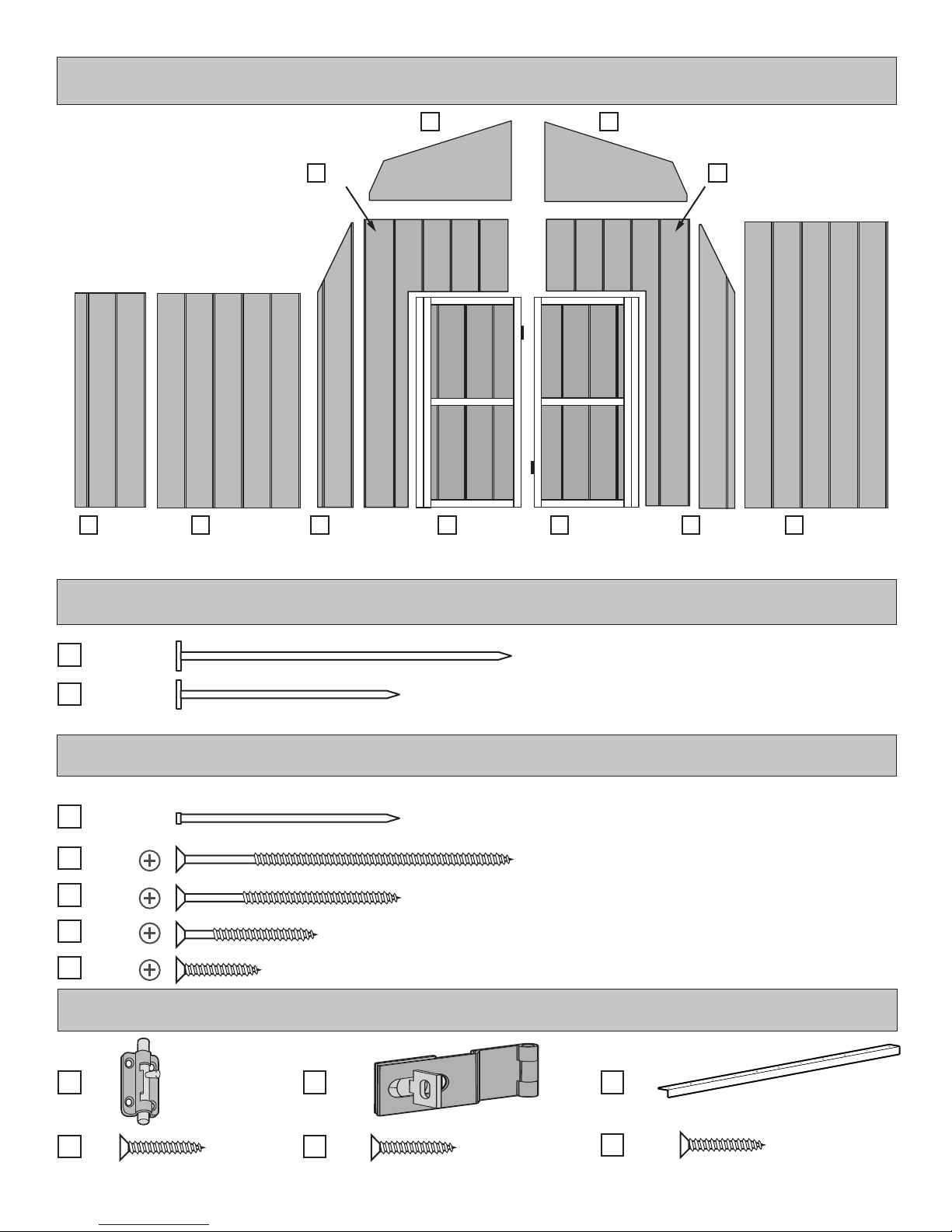
PARTS LIST
3/4" (1,9 cm)
2 x 3 x 22-1/2" (5 x 7,6 x 57 cm)
2 x 3 x 25" (5 x 7,6 x 63,5 cm)
2 x 3 x 45" (5 x 7,6 x 114,3 cm)
2 x 3 x 46-1/4" (5 x 7,6 x 117 cm)
2 x 3 x 48" (5 x 7,6 x 122 cm)
2 x 3 x 68-3/4 " (5 x 7,6 x 174,6 cm)
2 x 3 x 70-1/4" (5 x 7,6 x 178 cm)
2 x 3 x 94-1/2" (5 x 7,6 x 240 cm)
2 x 3 x 96" (5 x 7,6 x 244 cm)
x8
x8
x2
x4
x2
x4
x4
x4
x2
x4
x2
KP
HHP
SU
JRA
PD
PF
HQ
OB
OO
6 x 24" (15 x 61 cm)
Pre-assembled
1 x 4 x 96" (2,5 x 10 x 244 cm)
2 x 4 x 28-3/4" (5 x 10 x 70 cm)
2 x 4 x 59-3/4" (5 x 10 x 152 cm)
2 x 4 x 92-5/16" (5 x 10 x 234 cm)
2 x 3 x 45-1/8" (5 x 7,6 x 115 cm)
2 x 3 x 41" (5 x 7,6 x 104 cm)
1 x 3 x 94-1/2" (2,5 x 7,6 x 240 cm)
2 x 3 x 72-5/8" (5 x 7,6 x 184,5 cm)
2 x 3 x 69" (5 x 7,6 x 175,3 cm)
DOOR RAFTERSTRIM WALLSLOFT
x1
ZJ
5/8 x 3 x 72" (1,6 x 7,6 x 183 cm)
4
x1
x2
PANEL PARTS LIST
NOTE: Panel parts are not stamped with part identifi cation.
7/16 x 48 x 96"
(1,1 x 122 x 244 cm)
Loft panel is
7/16" (1,1 cm) thick.
7/16 x 23-7/8 x 41-7/8"
(1,1 x 61 x 106 cm)
ROOF PANELS LOFT
x2
x2
x2
7/16 x 23-7/8 x 45-1/8"
(1,1 x 61 x 115 cm)
7/16 x 41-7/8 x 96"
(1,1 x 106 x 244 cm)
Roof panels are
7/16" (1,1 cm) thick.
7/16 x 45-1/8 x 96"
(1,1 x 115 x 244 cm)
NOTES
5
WALL PANEL & DOORS PARTS LIST
x2x2
x1 x1
x2
3/8 x 23-7/8 x 72"
(1 x 61 x 183 cm)
BOXES
x2
BOXES
x5
x28
x57
x18
x84
x50
x4
3/8 x 48 x 72"
(1 x 122 x 183 cm)
x2
x1
LEFT DOOR
x1
RIGHT DOOR
x2
NAIL BOXES (Shown Actual Size)
3" (7,6 cm)
2" (5,0 cm)
FASTENER/HARDWARE BAG (Shown Actual Size)
2" (5,0 cm)
3" (7,6 cm)
2" (5,0 cm)
1-1/4" (3,2)
3/4" (1,9 cm)
x2
3/8 x 48 x 96"
(1 x 122 x 244 cm)
DOOR HARDWARE (Not Actual Size)
x1 x1 x1
x4 x7
3/4" (1,9 cm) 3/4" (1,9 cm)
64" Metal Threshold
x11
Bagged seperately / special coating
3/4" (1,9 cm)
6
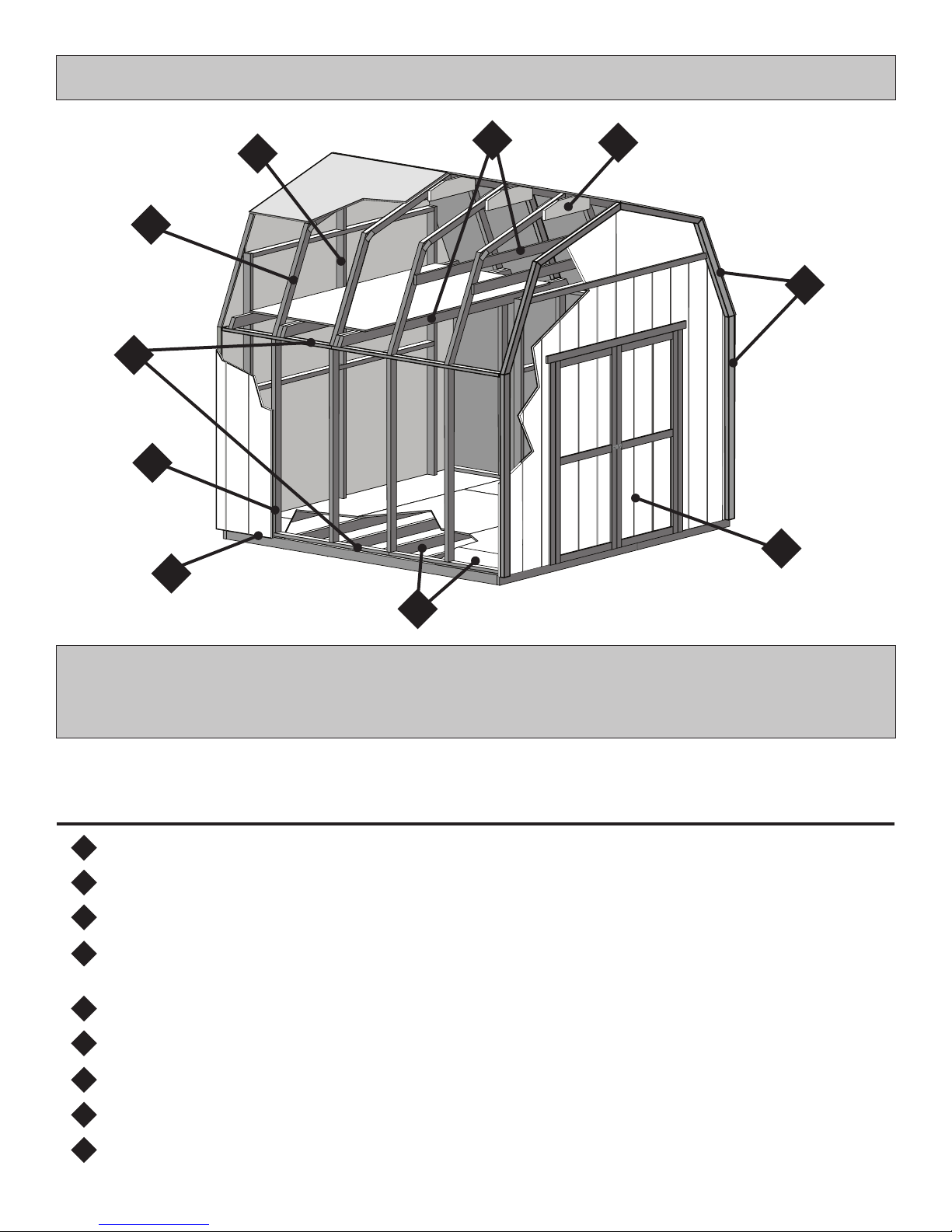
BUILDING ANATOMY
3
4
2
5
8
6
4
7
1
9
This building has been designed using our patented EZ Frame construction method.
EZ Frame is a unique construction method which has been engineered to use fewer
framing members. This reduces assembly time and cost by as much as 30% compared to
conventional construction methods. EZ Frame patent no. 5,666,766
All of our buildings have been engineered to withstand demanding wind and snow loads.
If you live in an area with extreme wind/snow load requirement, contact
us and we can assist with engineering to meet your local codes.
1 Sub-assembled doors.
2
2. 2x3 wall studs have been engineered to support roof load and to meet demanding wind loads.
3
3. Sidewall top and bottom plates tie wall studs together and provide nailing support for top and bottom edge of siding.
4
4. Rafters line up over wall studs to effectively transfer roof load to the oor and eliminate need for double top plate.
Oversized wood gussets at peak provide a strong connection for rafter halves.
5. Treated siding overhangs the wall framing and oor to keep the elements out.
5
6
6. Collar ties and storage loft tie sidewalls together to prevent spreading under heavy roof loads.
7. Corner studs & end rafters are positioned to the outside of the siding where they serve the dual purpose of framing and trim.
7
8 The EZ Frame design transfers the roof load to the side walls allowing for reduced framing at the front and back wall.
9
9. Treated oor frame and Oriented Strand Board (OSB) oor (not included).
7
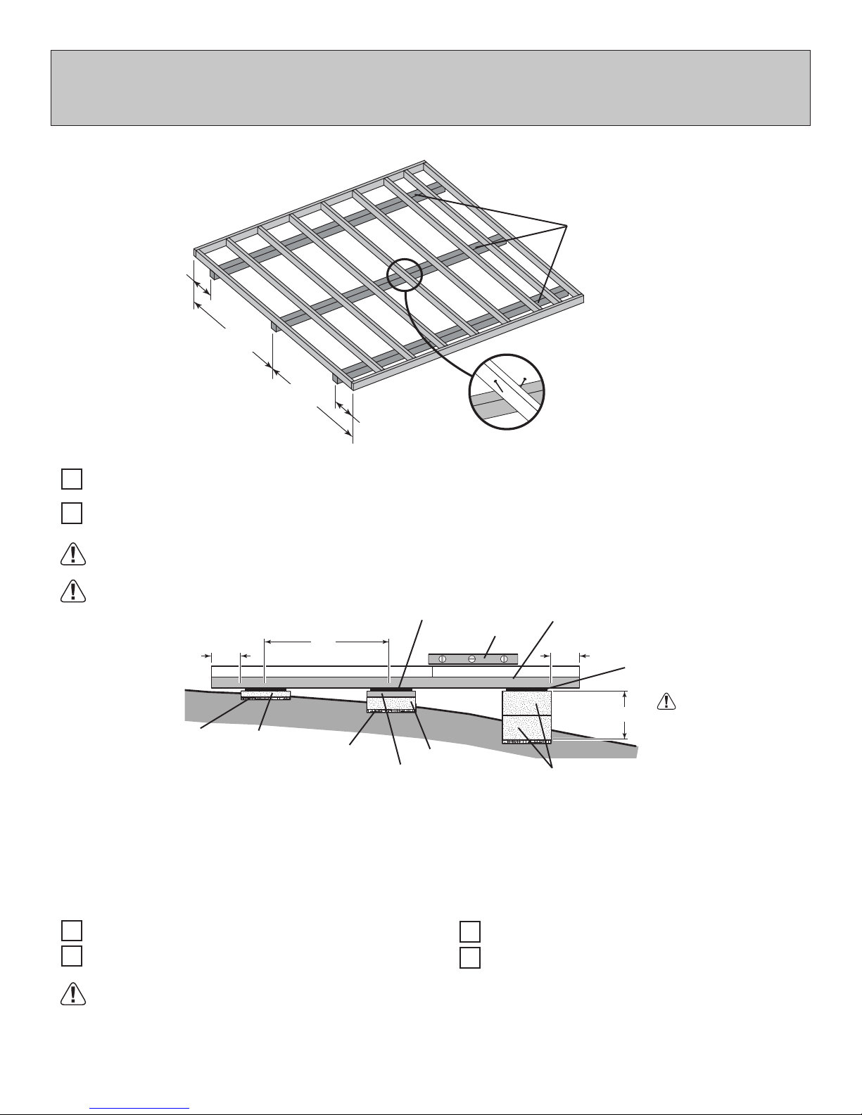
FLOOR LEVELING OPTIONS
There are multiple ways to level your oor frame. Our recommended leveling method is shown below.
Leveling materials are not included in this kit.
PREFERRED METHOD - 4x4 TREATED RUNNERS
4x4 Runners
(not included).
12"
(30,4 cm)
60"
(152,4 cm)
60"
(152,4 cm)
12"
(30,4 cm)
• 3" Screw angled into 4x4.
• (2) at each point frame and 4x4 touch.
MATERIAL REQUIRED
4" x 4" x 116-5/8" (10 x 10 x 296,2 cm) Treated Lumber
x3
Fasteners for Frame to 4"x 4"
(3" Screws shown as one option.) Minimum (48) 3" screws / exterior grade.
Use only wood treated for ground contact and fasteners approved for use with treated wood.
Always support frame seams.
Shingle
Level
4" Block
2x4 Treated Lumber
12"
Gravel
LEVELING METHODS
Maximum between leveling
material locations.
48"
2" Block
Gravel
• Level under 4x4 runners only.
• Locate leveling material 12" from ends of runners and no more than 48" apart.
• Asphalt shingles should be used between 4x4 runners and blocks or treated lumber. Never use
shingles in direct contact with ground.
• For best results and aiding in water drainage use gravel under each concrete block.
4x4 Runner
12"
8" Block
Shingle
Do not exceed 16".
LEVELING MATERIALS
Gravel
Solid Masonry Blocks in 1", 2", 4" or 8" thickness
Leveling higher than 16" not recommended.
CONCRETE
• If you are building your shed on a concrete foundation see the following page.
2x4 Treated Lumber
Asphalt Shingles
8
If you choose to install your kit on a concrete slab refer to the diagram below.
Treated Sill Plate
Caulk between sill plate
and concrete.
CONCRETE FOUNDATION
3-1/2"
(8,9 cm)
B
C
A
DOOR
4"
(10 cm)
A B CActual Floor SizeBuilding Size
10'x 10' (305 x 305 cm)
Allow new concrete slabs to cure for at least seven (7) days.
• A treated 2 x 4" (5 x 10 cm) sill plate is required when installing your shed on concrete. Hint: Purchase full length treated lumber.
• Use a high quality exterior grade caulk beneath all sill plates.
• Fasten 2 x 4" (5 x 10 cm) sill plates to slab using approved concrete anchors (fasteners not included).
• Check local code for concrete foundation requirements.
10'x 9'-8-5/8" (305 x 296,2 cm)
Requires:
2 x 4 x10' (5 x 10 x 305 cm)
x4
Caulk
x1
120" (305 cm)
109-5/8" (278,4 cm)
MUST be treated lumber.
116-5/8" (296,2 cm)
NOTES
9
[40,6 cm]
32”
16”
[81,2 cm]
48” [121,9 cm]
64” [162,5 cm]
80” [203,2 cm]
96” [243,8 cm]
106” [269,2 cm]
116
5
8
" [296,2 cm]
10 "
5
8
[27 cm]
117"
[297.18 cm]
120"
[3048 cm]
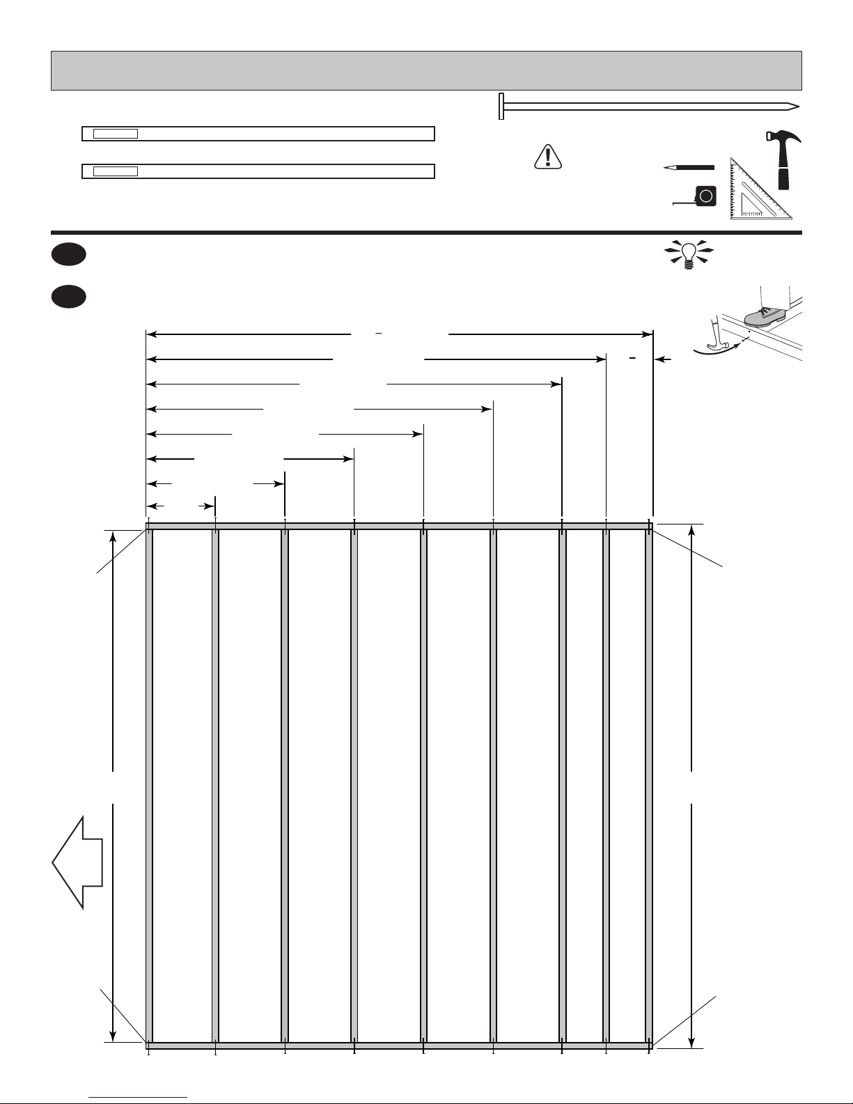
FLOOR FRAME (NOT INCLUDED)
PARTS REQUIRED (Not Included In Kit):
TREATED
x2
2 x 4 x 116-5/8" (5 x 10 x 296,2 cm) Treated Wood
TREATED
x9
2 x 4 x 117" (5 x 10 x 297,2 cm) Treated Wood
NOTE:
Use Treated Lumber For Floor Framing
Cut treated 2 x 4 x 120" lumber down to lengths and quantities as shown.
1
Orient parts as shown on at surface. Measure and mark from end of boards.
2
Use two 3" nails at each mark.
Floor framing materials
not included. See page 3
for sizes and quantities.
3" (7,6 cm) x36
HINT:
For easier nailing
stand on frame.
Flush
at ends
DOOR
Flush
at ends.
Flush
at ends
Flush
at ends.
10
FLOOR FRAME (NOT INCLUDED)
3" (7,6 cm) x6
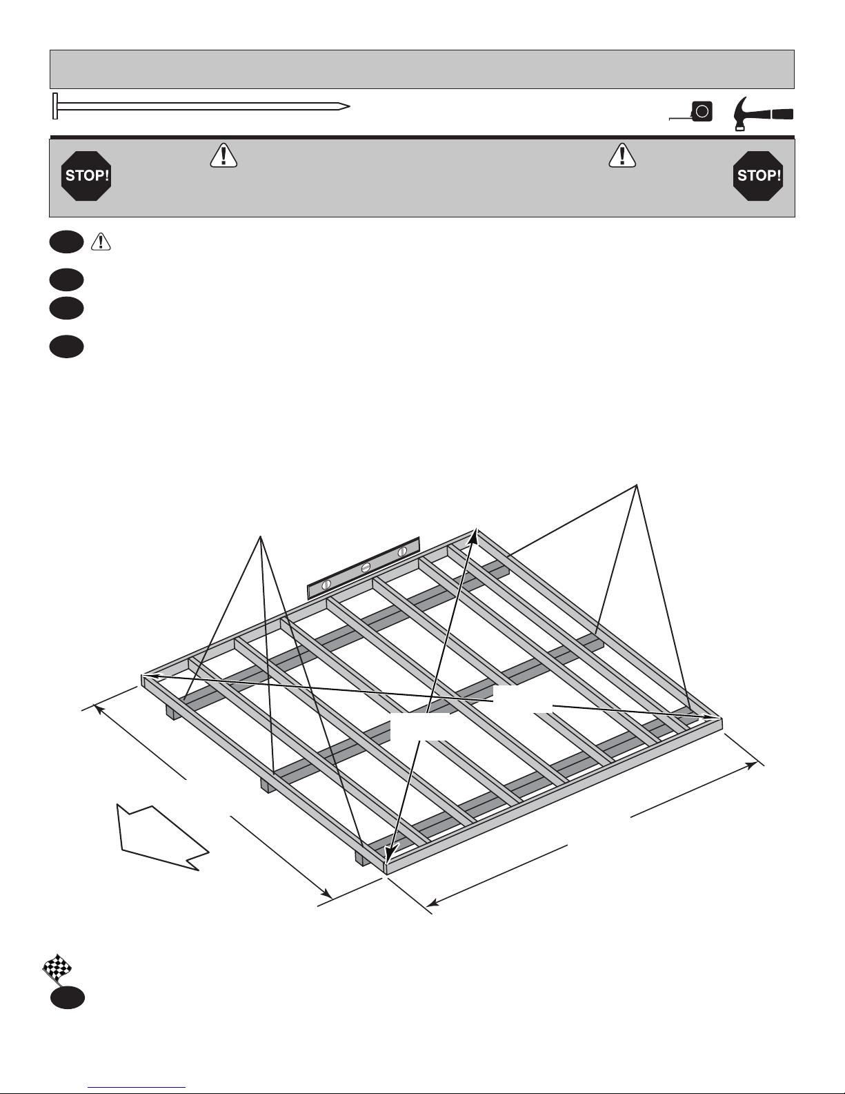
LEVEL AND SQUARE FLOOR FRAME
Before attaching oor decking, it is important to level and square the oor frame.
A level and square oor frame is required to correctly construct your shed.
3
See page 8 for the preferred oor leveling method.
4
Use level and check the frame is level before applying oor panels.
Check for frame squareness by measuring diagonally across corners. If the measurements are the
5
same, the frame is square. The diagonal measurement will be approximately 167-3/8" (425 cm).
6
When the frame is level and square secure one side of frame to the 4x4 runners using one fastener at
ends of each runner. At the opposite end of the frame, secure the frame to 4x4 runners with one fastener
at ends of each runner making sure the frame remains square (Fig. A).
Second, secure
at ends with
one fastener.
First, secure at ends with
one fastener.
120"
(305 cm)
DOOR
167-3/8"
(425 cm)
167-3/8"
(425 cm)
116-5/8"
(296 cm)
Fig. A
FINISH
Once the oor frame is level and square, fasten the frame at each point the frame contacts the 4x4
7
runners.
11
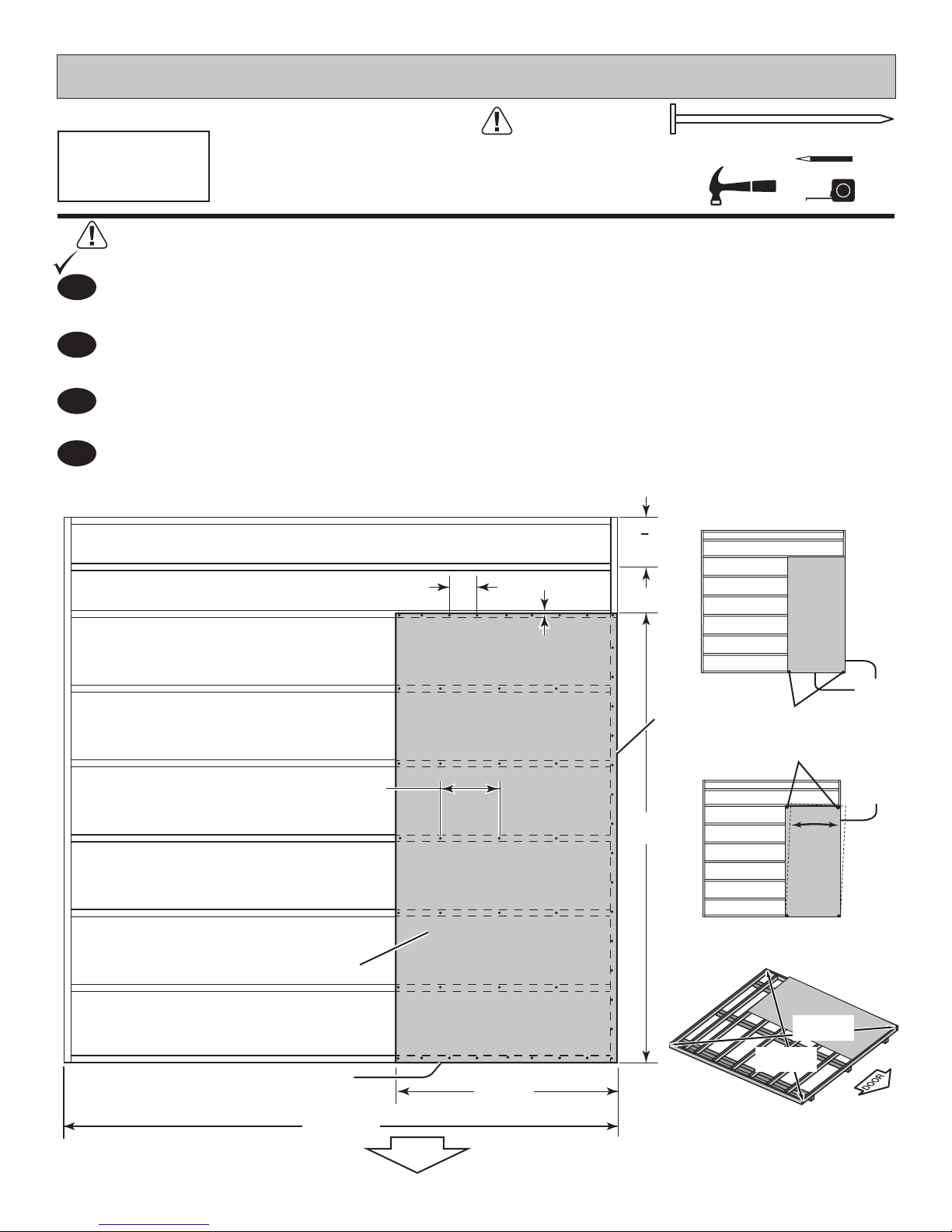
FLOOR PANELS (NOT INCLUDED)
PARTS REQUIRED:
x1
Ensure your fl oor frame is square by installing one panel and squaring frame.
BEGIN
Attach the 5/8 x 48 x 96” panel with the rough side up (painted grid lines side) with the 48”
1
edge and corner flush to the floor frame (Fig A). Secure panel with two 2” nails in the corners
Move to the opposite end. Using the long edge of the panel as a lever, move the panel side-to-side until the
2
top corner is flush to the floor frame (Fig. B). Secure panel with two 2" nails in the corners.
Check the floor frame is square by measuring diagonally across the frame corners. If the measurements are the
3
same your floor frame is square. The measurement will be approximately 167-3/8" (425 cm) (Fig. C).
4
Continue attaching the panel using 2" nails 6" apart on edges and 12" apart inside panel. Use a chalk line or use
pre-painted grid lines to nail into joists under panel.
5/8 x 48 x 96"
(1,6 x 122 x 243,8 cm)
Floor Panels not included
See page 3 for panel sizes
and quantities.
5
10 "
8
[27 cm]
2" (5 cm) x45
6" (15 cm) edges of panel.
12" (30,5 cm) inside panel
Grid lines UP
Flush
120"
(305 cm)
DOOR
48"
(122 cm)
3/4" (1,9 cm)
Flush
96"
(243,8 cm)
(2) Nails
(2) Nails
167-3/8"
(425 cm)
Fig. A
Flush
Flush
at top
corner
edge.
Fig. B
167-3/8"
(425 cm)
Fig. C
12
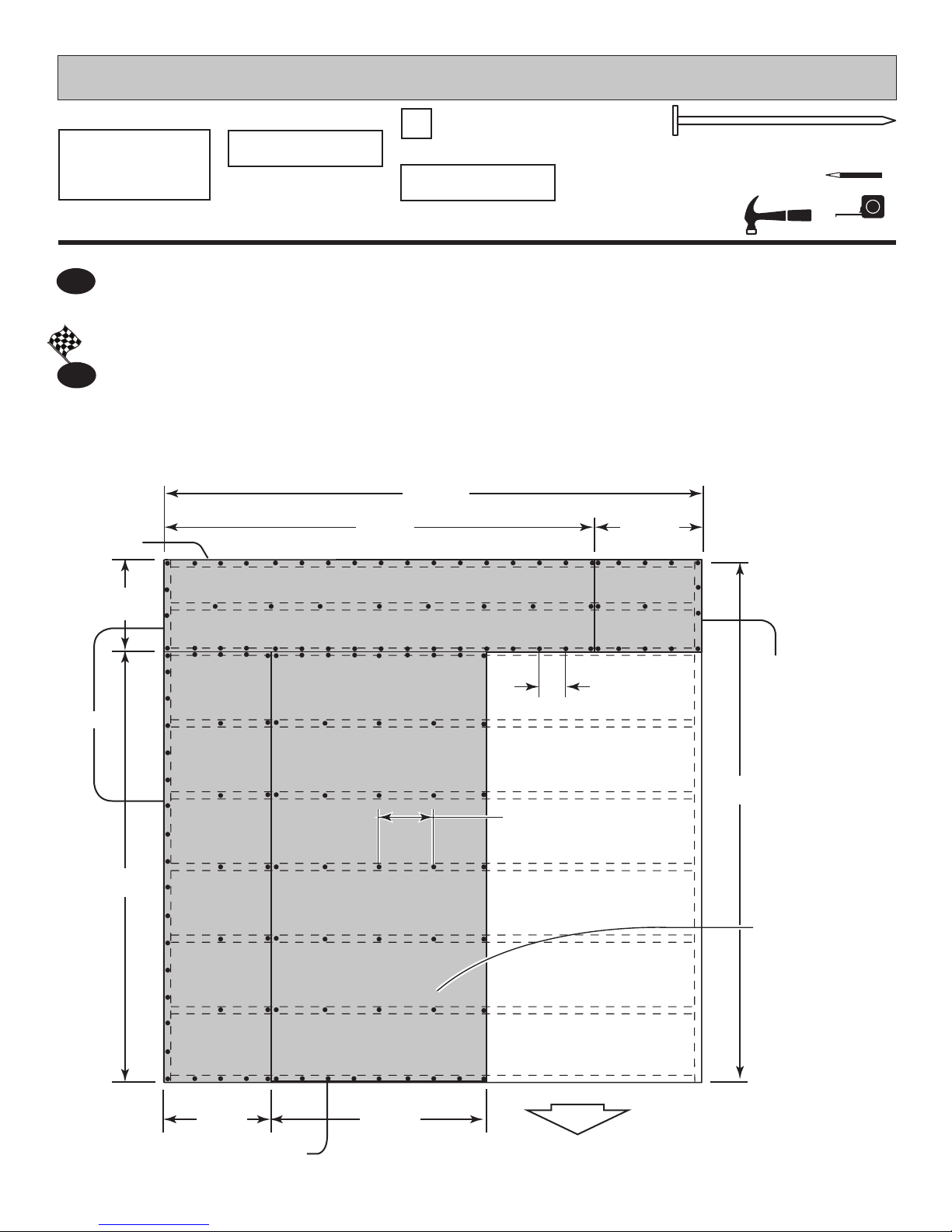
FLOOR PANELS (NOT INCLUDED)
PARTS REQUIRED:
x1
5/8 x 48 x 96"
(1,6 x 122 x 243,8 cm)
Continue installing panels with rough side up (painted grid lines).
4
Use a chalk line or grid lines on panels for 2" nails 6" apart on edges and 12" apart inside panel.
FINISH
5
You have finished Installing your floor panels.
Flush
5/8 x 20-5/8 x 96"
(1,6 x 52,4 x 243,8 cm)
x1
x1
5/8 x 23-7/8 x 96"
(1,6 x 60,4 x 243,8 cm)
120"
(305 cm)
96"
(244 cm)
5/8 x 20-5/8 x 23-7/8"
(1,6 x 52,4 x 60,4 cm)
x1
2" (5 cm) x137
23-7/8"
(60,6 cm)
20-5/8"
(61 cm)
Flush
(243,8 cm)
Flush
6" (15 cm)
.
116-5/8"
(296 cm)
12" (30,5 cm)
96"
Grid lines UP
23-7/8"
(61 cm)
Flush
48"
(122 cm)
DOOR
13
IMPORTANT!
IMPORTANT!
Check the oor frame is level after installing oor panels. Re-level if needed.
HINT:
BACKWALL
DOOR
• The oor should be used as a level work surface for wall construction.
• Organize your wall sections during subassembly
to avoid over-handling of the walls.
SIDEWALL
SIDEWALL
DOOR
FRONTWALL
14
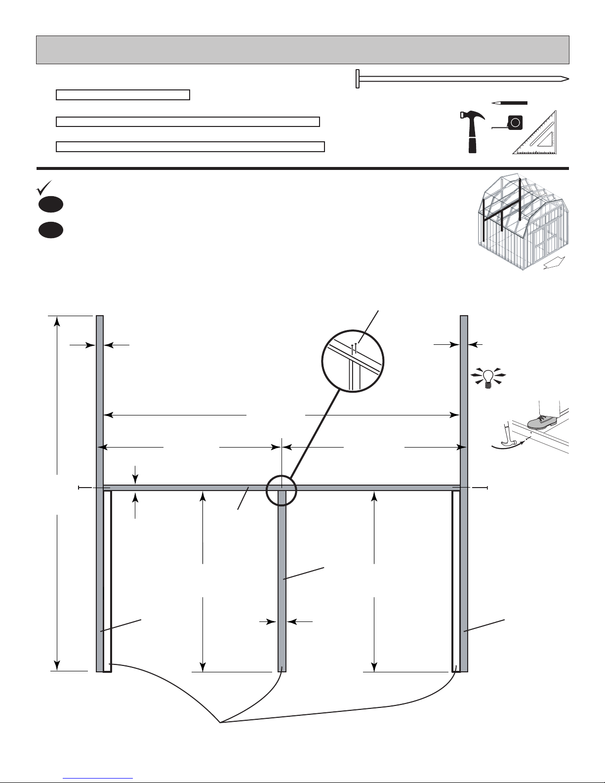
BEGIN
(244 cm)
BACK WALL FRAME
PARTS REQUIRED:
x1
x1
x2
NK
2 x 3 x 48" (5 x 7,6 x 122 cm)
PR
2 x 3 x 94-1/2" (5 x 7,6 x 240 cm)
PT
2 x 3 x 96" (5 x 7,6 x 244 cm)
Orient parts on edge on oor as shown.
1
Nail using two 3" nails at each connection.2
1-1/2"
(3,8 cm)
3" (7,6 cm) x6
DOOR
(2) 3" (7,6 cm) Nails
1-1/2"
(3,8 cm)
96"
94-1/2"
(240 cm)
48-3/4"
(124 cm)
48-3/4"
(124 cm)
PR
1-1/2"
(3,8 cm)
48"
(122 cm)
PT PT
NK
1-1/2"
(3,8 cm)
48"
(122 cm)
HINT:
For easier nailing
stand on frame.
Use NK as a guide to locate PR. (Do not nail.)
15
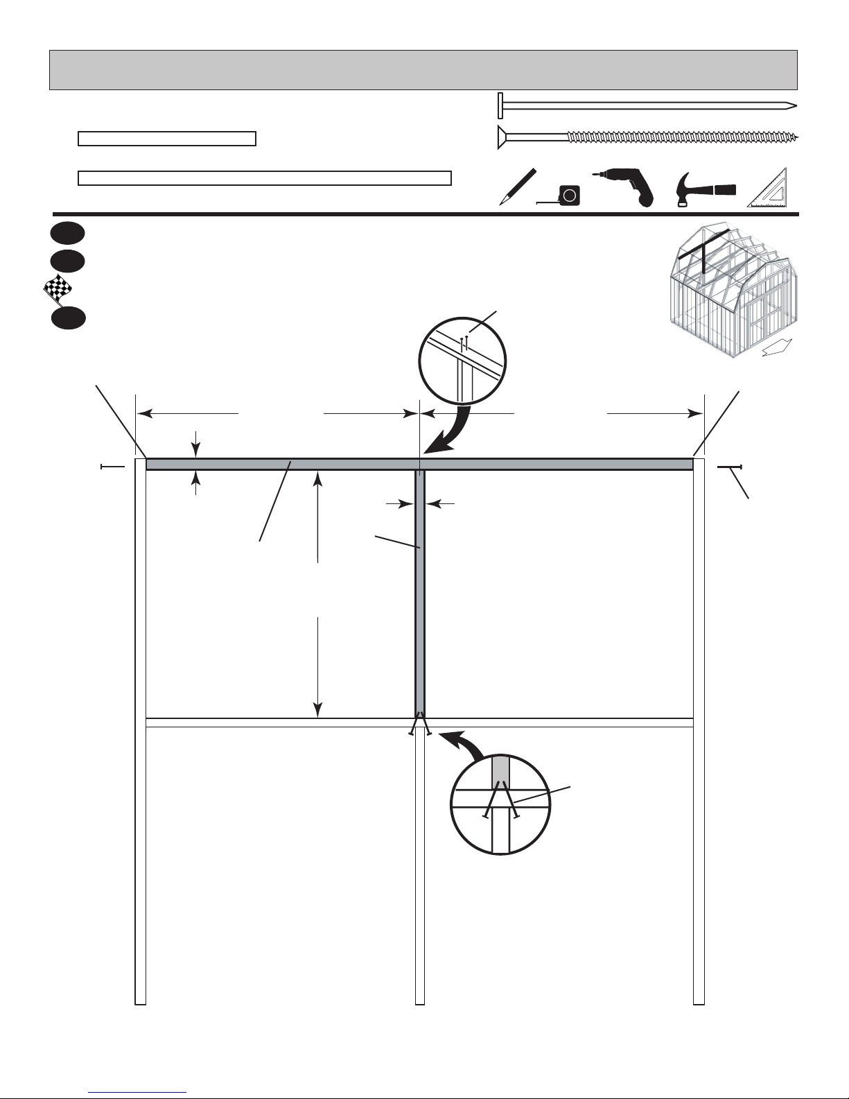
48-3/4"
BACK WALL FRAME
PARTS REQUIRED:
x1
x1
3
4
FINISH
NC
2 x 3 x 45" (5 x 7,6 x 114,3 cm)
PR
2 x 3 x 94-1/2" (5 x 7,6 x 240 cm)
Orient parts on edge on oor as shown.
Nail using two 3" nails at each connection and two 3" screws at middle connection.
You have nished building your back wall frame.
5
1-1/2"
(3,8 cm)
(124 cm)
PR
(2) 3" (7,6 cm) Nails
48-3/4"
(124 cm)
1-1/2"
(3,8 cm)
3" (7,6 cm) x6
3" (7,6 cm) x2
DOOR
Flush
(2) 3"
(7,6 cm)
Nails
45"
(114 cm)
(2) 3" (7,6 cm)
Screws
16
(1,9 cm
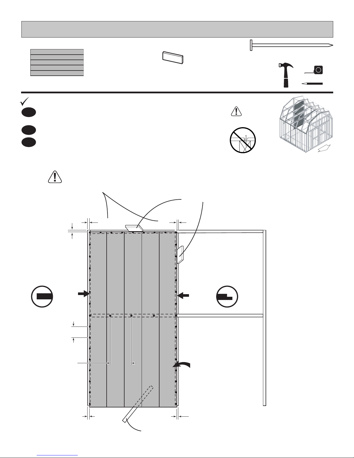
BEGIN
PARTS REQUIRED:
BACK WALL PANELS
2" (5 cm) x44
x1
3/8 x 48 x 96"
(1 x 122 x 244 cm)
3/4"
GAUGE
BLOCK
Place panel on back frame as shown with primed side facing up.
1
Note: Orient square and lip edges as shown.
Use a 3/4" gauge block at edges of panel.
2
3
Nail using 2" nails 6" apart on edges and 12" apart inside panel. .
For squareness maintain
3/4" measurement along
panel edges.
3/4" Gauge Block
3/4"
(1,9 cm)
3/4"
(1,9 cm)
Do not nail
in groove.
DOOR
3/4"
SQUARE
EDGE
6" (15 cm)
12" (30,5 cm)
)
LIP EDGE
Install with primed
side facing up.
3/4"
(1,9 cm)
3/4"
(1,9 cm)
Use a 2x3" for support.
17
 Loading...