

Heartland 16019 Assembly Manual
STOP!
STOP!
16019
Call Us First!
DO NOT RETURN TO STORE.
For immediate help with assembly or product information
call our toll free number:
1-800-577-9663
or email:
customerservice@backyardproductsllc.com
Our staff is ready to provide assistance
April through October M-F 8:00 AM to 4:30 PM EST
Saturday 8:30 AM to 4:30 PM EST
November through March M - F 8:00 AM to 5:00 PM EST

(This page intentionally left blank.)
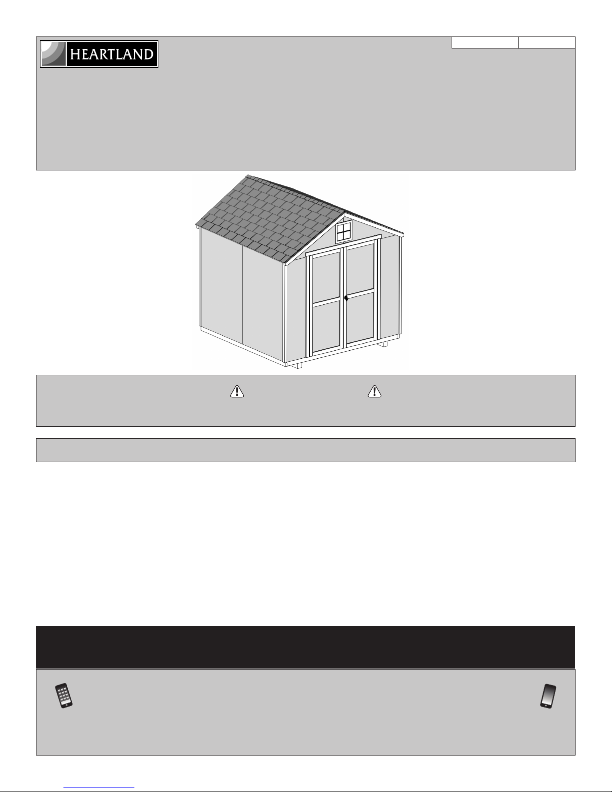
ASSEMBLY MANUAL
• BUILDING RESTRICTIONS AND APPROVALS
.
You will need additional materials to complete your shed. See page 4 for required and optional materials and quantities.
A Backyard Products Company
VALUE SERIES
BELMONT 8' x 8' (244 x 244 cm)
ACTUAL FLOOR SIZE IS: 96 x 92-5/8" (243,8 x 235,2 cm)
KEEP THIS MANUAL FOR FUTURE REFERENCE
16019
10/13/2017
READ INSTRUCTIONS THOROUGHLY PRIOR TO BEGINNING ASSEMBLY.
Be sure to check with local
• ENGINEERED DRAWINGS
Contact our Customer Service Team if engineered drawings are needed to pull local permits.
• SURFACE PREPARATION
To ensure proper assembly you must build your shed on a level surface. Recommended methods and materials to level your shed are
listed on page 7.
• CHECK ALL PARTS
Inventory all parts listed on pages 5 - 6. Contact our Customer Service Team if any parts are missing or damaged.
• ADDITIONAL MATERIALS
Call: 1- 800- 577- 9663 email: customerservice@backyardproductsllc.com
building department and homeowners association for specifi c restrictions and/ or requirements before building
IMPORTANT!
BEFORE YOU BEGIN
- CUSTOMER SERVICE -
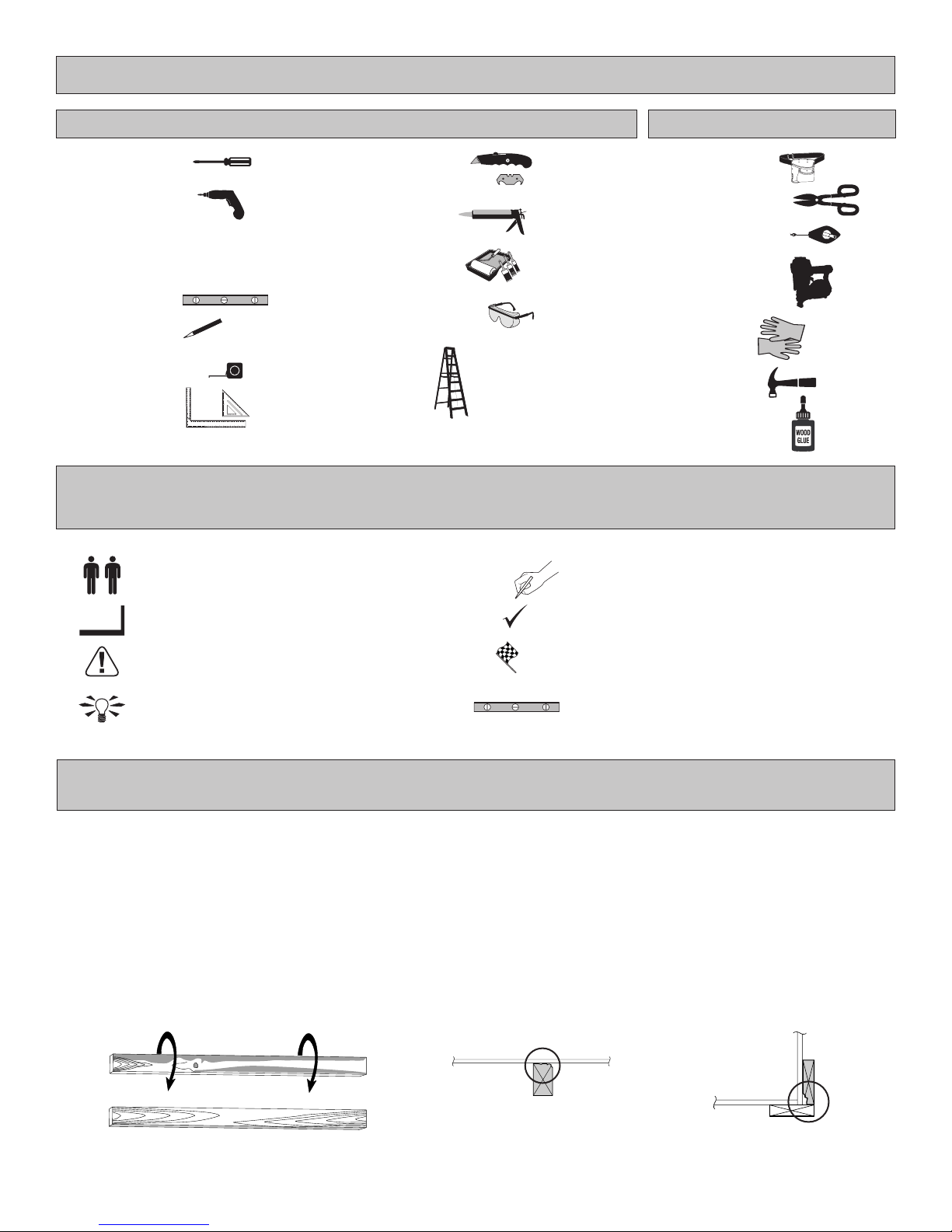
TOOLS
BEGIN
OptionalRequired
q Phillips
Screwdriver
q Drill / Driver
q 5/16" Drill Bit
q 1/8" Drill Bit
q #2 Philips Drive Bit
q Level
q Pencil
q Tape Measure
q Square
or
Safety! Always use approved safety glasses during assembly.
HELPFUL REMINDER SYMBOLS
Look for these symbols for helpful reminders throughout this manual.
= Assistance Required; two or more people.
= Ensure squareness.
= Important required step or operation.
= Helpful assembly hint.
q Utility Knife
q Shingle Blades
q Caulk Gun
q Paint Tools
q Safety Glasses
q Ladder
FINISH
q Tool Belt/
Nail Pouch
q Tin Snips
(for drip edge)
q Chalk Line
q Nail Gun
• gun nails
q Gloves
q Hammer
q Wood Glue
= Mark part with pencil.
= Beginning of steps for assembly or installation.
= You have nished the assembly or installation.
= Level
ORIENT LUMBER AND TRIM FOR BEST APPEARANCE
Framing lumber is graded for structural strength and not appearance. Exterior trim is graded for one good side.
Always install the material leaving the best edge and best surface visible. Please remember that these blemishes in no way
negatively affect the strength or integrity of our product. (See Fig. A, B, C.)
A
B C
2
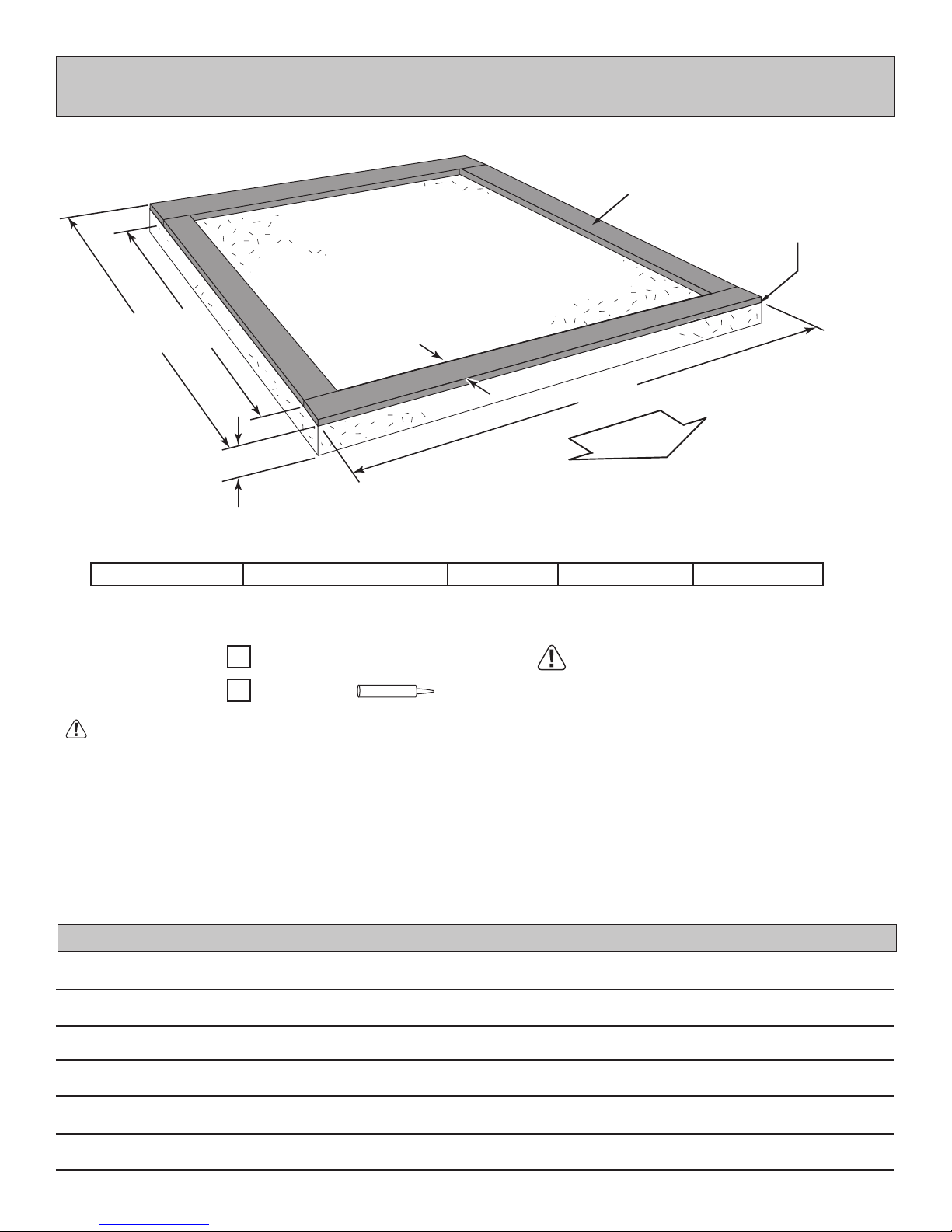
CONCRETE FOUNDATION
D
O
O
R
If you choose to install your kit on a concrete slab refer to the diagram below.
Treated Sill Plate
Caulk between sill plate
and concrete.
B
8'x 8' (243,8 x 243,8 cm)
Allow new concrete slabs to cure for at least seven (7) days.
C
4"
(10,2 cm)
Requires:
8'x 7'-8-5/8" (243,8 x 235,2 cm)
x4
2 x 4 x 8' (5,1 x 10,2 x 243,8 cm)
Caulk
x1
3-1/2"
(8,9 cm)
A B CActual Floor SizeBuilding Size
96" (243,8 cm)
A
92-5/8" (235,3 cm)
MUST be treated lumber.
85-5/8" (217,5 cm)
• A treated 2 x 4" (5,1 x 10,2 cm) sill plate is required when installing your shed on concrete. Hint: Purchase full length treated lumber.
• Use a high quality exterior grade caulk beneath all sill plates.
• Fasten 2 x 4" (5,1 x 10,2 cm) sill plates to slab using approved concrete anchors (fasteners not included).
• Check local code for concrete foundation requirements.
NOTES
3
ADDITIONAL MATERIALS FOR BUILDING YOUR SHED
ethods to build your shed on a poured concrete slab.
3-TAB SHINGLES ............................ 4 Bundles
PAINT FOR SIDING .......................... 2 Gallons
Use 100% acrylic latex exterior paint. (2) coats recommended.
CAULK ................................................. 2 Tubes
Use acrylic latex exterior caulk that is paintable.
1" GALVANIZED ROOFING NAILS.... 2 Lbs
For shingles.
PAINT FOR TRIM .............................1 Quart
Use 100% acrylic latex exterior paint.
WOOD GLUE ....................... Exterior Rated
FOUNDATION
• This shed kit does not include a wood floor frame or floor panels. See pages 8 through 11 for suggested floor construction.
• It does not include ANY leveling materials.
See the FLOOR LEVELING section on page 7 for recommended methods and suggested materials to properly level your
•
floor, as this will vary depending on your specific site.
See the CONCRETE FOUNDATION section on page 3 for recommended m
•
WOOD FLOOR FRAME (NOT INCLUDED)
MATERIAL LIST: CUT LIST:
2 x 4 x 96” (5 x 10 x 243,8 cm)
x9
10D 3” (7,6 cm) Hot Dipped Galvanized Nails
x28
Treated Lumber
2 x 4 x 93" (5 x 10 x 236,2 cm)
x7
x2
2 x 4 x 92-5/8" (5 x 10 x 235,2 cm)
Use Treated Lumber For
Floor Framing
FLOOR PANELS (NOT INCLUDED)
MATERIAL LIST: CUT LIST:
5/8 x 48 x 96” (1,6 x 122 x 243,8 cm) OSB Panels
x2
(Recommend 5/8” (1,6 cm) (minimum) thick OSB panels)
x106
6D 2” (5,0 cm) Hot Dipped Galvanized Nails
x2
5/8 x 48 x 92-5/8" (1,6 x 122 x 235,2 cm)
REINFORCED WOOD FLOOR FRAME (OPTIONAL)
IMPORTANT!
Depending on your specific use, you may want to construct a heavy
duty floor frame by adding additional floor joists. Below is a list in
addition to the framing materials above (not included):
2 x 4 x 96” (5 x 10 x 243,8 cm)
x2
Cut to: 2 x 4 x 93" (5 x 10 x 236,2 cm)
ea. 10D 3" (7,6 cm) Hot Dipped Galvanized Nails
x8
Treated Lumber
OPTIONAL MATERIALS
DRIP EDGE ..................... 40 Feet #15 ROOFING FELT
To cover 75 Sq. Ft. of r oof area.
1" GALVANIZED ROOFING NAILS.........1/4 Lb
For roofing felt.
Optional
12" (30,5 cm)
spacing
REFER TO THE BACK OF THIS MANUAL AND THE MANUFACTURER’S INSTRUCTIONS
FOR INSTALLATION OF SHINGLES, DRIP EDGE AND FELT.
4

stamped on some parts.
RS
• Check these locations for part stamp.
RS
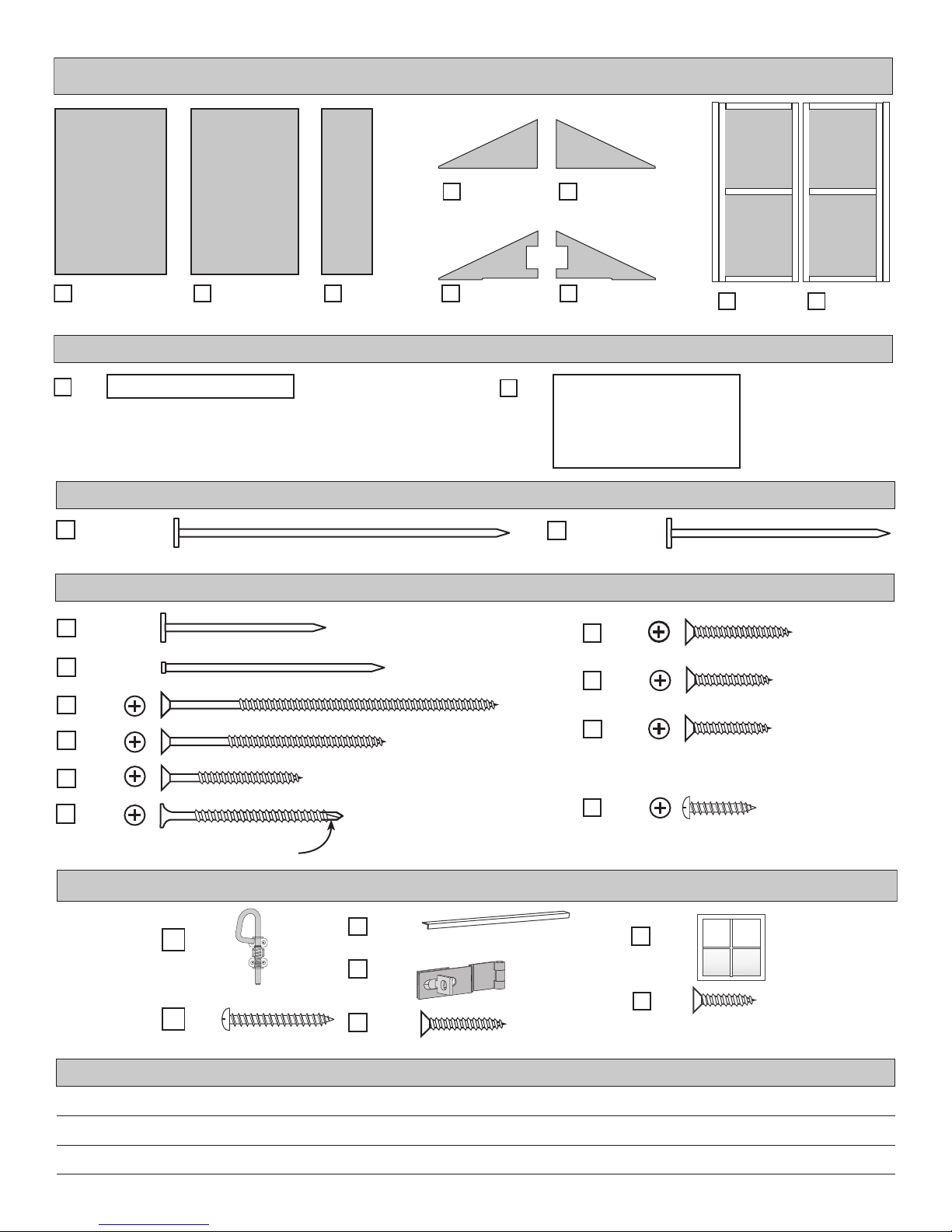
INVENTORY YOUR PARTS before you begin.
We suggest sorting parts by the category they are listed in.
GAA
x1
x2
1 x 3 x 5" (2,5 x 7,6 x 12,7 cm) GAUGE BLOCK FOR 3/4" (1,9 cm) MEASUREMENT
DQ
2 x 3 x 11-7/8" (2,5 x 7,6 x 30,2 cm)
PARTS IDENTIFICATION AND SIZES
WOOD SIZE CONVERSION CHART
Nominal Board Size Actual Size
2" x 4"..............1-1/2" x 3-1/2" (3,8 x 8,9 cm)
1" x 4".................3/4" x 3-1/2" (1,9 x 8,9 cm)
2" x 3"..............1-1/2" x 2-1/2" (3,8 x 6,3 cm)
1" x 3".................3/4" x 2-1/2" (3,8 x 6,3 cm)
PARTS LIST
3/4"
(1,9 cm)
x2
x1
x2
WALL
x11
x1
x4
x2
x6
x6
TRUSS
x2
BV
LW
CI
FZ
PS
PNA
PT
WI
WQ
2 x 3 x 17-1/2" (2,5 x 7,6 x 44,5 cm)
2 x 3 x 23-7/8" (2,5 x 7,6 x 60,6 cm)
2 x 3 x 34" (5,1 x 7,6 x 86,4 cm)
2 x 3 x 66-1/2" (5,1 x 7,6 x 168,9 cm)
2 x 3 x 91 " (5,1 x 7,6 x 231,1 cm)
2 x 3 x 92-1/2" (5,1 x 7,6 x 235 cm)
2 x 3 x 96" (5,1 x 7,6 x 243,8 cm)
6 x 24" (15,2 x 61 cm)
2 x 4 x 54-1/16" (5,1 x 10,2 x 129,8 cm)
1 x 2 x 11" (2,5 x 5,1 x 27,9 cm)
x2
x4
TRIM
x1
WO
WX
WR
1 x 2 x 14" (2,5 x 5,1 x 35,6 cm)
x4
x4
x2
OO
DOOR
2 x 3 x 55-3/4" (5,1 x 7,6 x 141,6 cm)
19/32 x 3 x 63" (1,5 x 7,6 x 160 cm)
3/8 x 1-3/4 x 71-1/4" (1 x 4,4 x 181 cm)
3/8 x 1-3/4 x 71-3/4" (1 x 4,4 x 182,2 cm)
1-1/4 x 2-1/2 x 69" (3,2 x 7,6 x 175,3 cm)
5
5
WALL PANELS, AND DOORS
x2
3/8 x 48 x 72"
(1 x 121,9 x 182,9 cm)
x2
x1 BOXES
x70
x64
x41
x20
x42
x8
x4
3/8 x 46-1/8 x 72"
(1 x 117,2 x 182,9 cm)
1-1/2" (3,8 cm)
2" (5,1 cm)
3" (7,6 cm)
2" (5,1 cm)
1-1/4" (3,2 cm)
1-5/8" (4,1 cm)
NOTE POINT
x2
3/8 x 20 x 72"
(1 x 50,8 x 182,9 cm)
x1
x1
x1
x1
x1
LEFT DOORx1RIGHT DOOR
ROOF PANELS
7-7/8" x 96"
(20 x 243,8 cm)
x2
48" x 96"
(121,9 x 243,8 cm)
Roof panels are
7/16" (1,1 cm)
thick.
NAIL BOXES
x3 BOXES
3" (7,6 cm) 2" (5,1 cm)
FASTENER/HARDWARE BAG
Bagged seperately /
For Window
x8
x70
x8
Bagged seperately / special coating
x12
1" (2,5 cm)
3/4" (1,9 cm)
3/4" (1,9 cm)
1/2" (1,3 cm)
DOOR HARDWARE / WINDOW
x1
x4
1" (2,5 cm)
x1
56" (142,2 cm) Metal Threshold
x1
x7
3/4" (1,9 cm)
NOTES
6
x1
x8
1/2" (1,3 cm)
FLOOR LEVELING OPTIONS
There are multiple ways to level your oor frame. Our recommended leveling method is shown below.
Leveling materials are not included in this kit.
PREFERRED METHOD - 4x4 TREATED RUNNERS
96"
(243,8 cm)
• 3" Screw angled into 4x4.
• (2) at each point frame
and 4x4 touch.
4x4 Runners
(not included).
12"
(30,5 cm)
D
O
O
R
12"
(30,5 cm)
Measurements to
centers of 4x4's.
MATERIAL REQUIRED
4" x 4" x 8' (10,2 x 10,2 x 243,8 cm) Treated Lumber
x2
Fasteners for Frame to 4"x 4".
(3" Screws shown as one option.) Minimum (20) 3" screws / exterior grade.
Use only wood treated for ground contact and fasteners approved for use with treated wood.
Always support frame seams.
Shingle
Level
4" Block
2x4 Treated Lumber
4x4 Runner
12"
8" Block
Shingle
Do not exceed 16".
12"
Gravel
LEVELING METHODS
Maximum between leveling
material locations.
48"
2" Block
Gravel
• Level under 4x4 runners only.
• Locate leveling material 12" from ends of runners and no more than 48" apart.
• Asphalt shingles should be used between 4x4 runners and blocks or treated lumber. Never use
shingles in direct contact with ground.
• For best results and aiding in water drainage use gravel under each concrete block.
LEVELING MATERIALS
Gravel
Solid Masonry Blocks in 1", 2", 4" or 8" thickness
2x4 Treated Lumber
Asphalt Shingles
Leveling higher than 16" not recommended.
CONCRETE
• If you are building your shed on a concrete foundation see the following page.
7
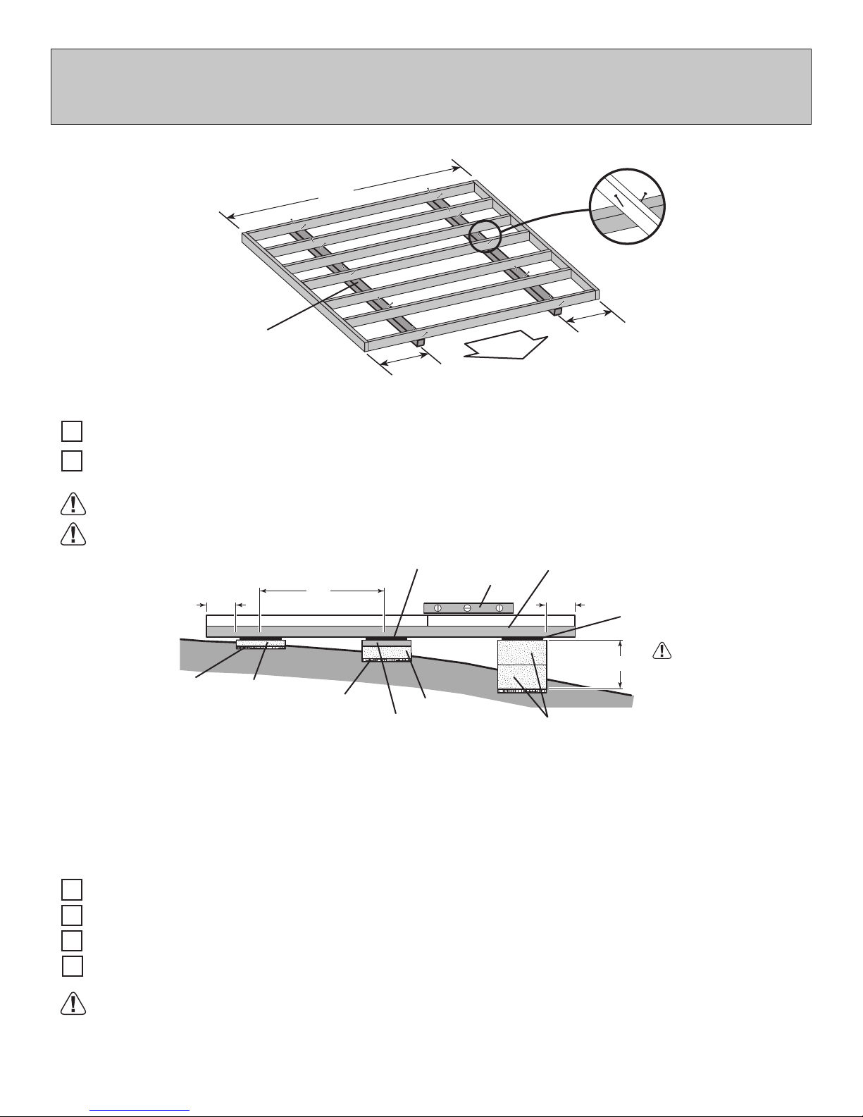
FLOOR FRAME (NOT INCLUDED)
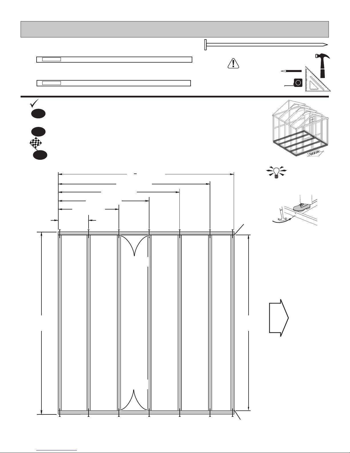
BEGIN
PARTS REQUIRED:
x5
x2
TREATED
2 x 4 x 96" (5,1 x 10,2 x 243,8 cm)
TREATED
2 x 4 x 92-5/8" (5,1 x 10,2 x 235,2 cm)
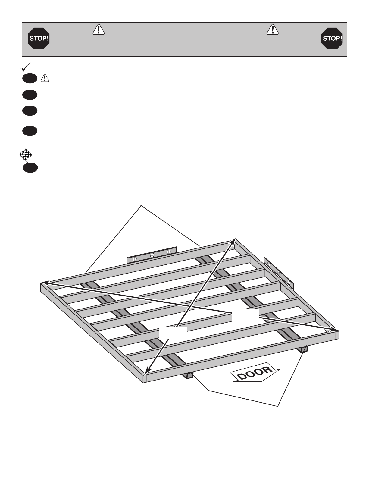
Orient parts as shown on at surface. Measure and mark each
1
dimension from end of boards
Use two 3" nails at each mark
2
FINISH
3
You have nished your oor frame. Proceed to level and square frame.
48" [121.9 cm]
32" [81.3 cm]
16"
[40.6 cm]
92
80" [203.2 cm]
64" [162.6 cm]
x28
Floor framing materials
not included. See page 4
for sizes and quantities.
• FOR 10' x 12', SKIP TO PAGE 16
5
" [235.2 cm]
8
3" (7,6 cm)
HINT:
For easier nailing
stand on frame.
Flush
at ends.
96"
[243.8 cm]
Center
on marks.
Center
on marks.
DOOR
93"
[236.2 cm]
Flush
at ends.
8
LEVEL AND SQUARE FLOOR FRAME
BEGIN
Before attaching oor decking, it is important to level and square the oor frame.
A level and square oor frame is required to correctly construct your shed.
1
See page 7 for the preferred oor leveling method.
2
Use level and check the frame is level before applying oor panels.
Check for frame squareness by measuring diagonally across corners. If the measurements are the
3
same, the frame is square. The diagonal measurement will be approximately 133-5/16" (338,6 cm).
4
When the frame is level and square secure one side of frame to the 4x4 runners using one fastener at
ends of each runner. At the opposite end of the frame, secure the frame to 4x4 runners with one fastener
at ends of each runner making sure the frame remains square (Fig. A).
FINISH
Once the oor frame is level and square fasten the frame at each point the frame contacts the 4x4
5
runners.
Second, secure at ends
with one fastener.
Fig. A
133-5/16"
(338,6 cm)
133-5/16"
(338,6 cm)
First, secure at ends
with one fastener.
9
5/8 x 48 x 92-5/8"
(1,6 x 122 x 235,2 cm)
PARTS REQUIRED:
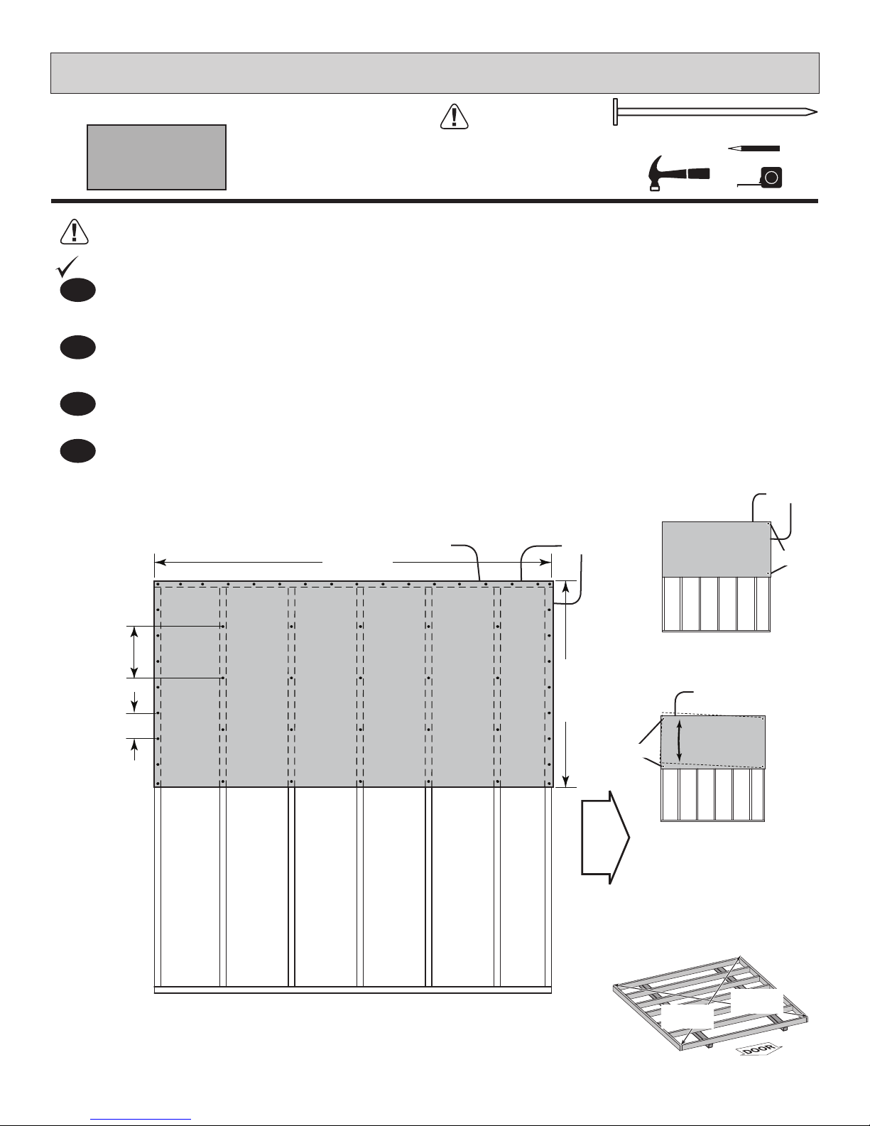
Ensure your fl oor frame is square by installing one panel and squaring frame.
FLOOR PANELS (NOT INCLUDED)
x1
2" (5,1 cm)
Fig. C
Flush
Fig. A
Flush at top
corner edge.
Fig. B
x53
Attach the 5/8 x 48 x 92-5/8" panel with the rough side up (painted-grid lines
side) with the 48" edge and corner fl ush to the fl oor frame (Fig A).
Secure panel with two 2" nails in the corners.
Move to the opposite end. Using the long edge of the panel as a lever move the
panel side-to-side until the top corner is fl ush to the fl oor frame (Fig. B).
Secure panel with two 2" nails in the corners.
2
BEGIN
1
3
4
Continue attaching the panel using 2" nails 6" apart on edges and 12" apart inside panel.
Use a chalk line or use pre-painted grid lines to nail into joists under panel.
Check the fl oor frame is square by measuring diagonally across the frame corners. If the measurements
are the same, your fl oor frame is square. The measurement will be approximately 133-5/16" (Fig. C).
133-5/16"
(338,6 cm)
133-5/16"
(338,6 cm)
92-5/8"
(235,2 cm)
48"
(121,9 cm)
Flush
12" (30,5 cm)
inside panel.
6" (15,2 cm)
edges of panel.
DOOR
Flush
Floor Panels not included
See page 4 for panel sizes
and quantities.
(2) Nails
(2) Nails
10
FLOOR PANELS (NOT INCLUDED)
PARTS REQUIRED:
x1
5/8 x 48 x 92-5/8"
(1,6 x 122 x 235,2 cm)
5
Continue by installing
Use a chalk line or grid lines on panels for 2" nails 6" apart on edges
and 12" apart inside panel.
FINISH
You have fi nished Installing your fl oor panels.
6
5/8 x
48 x 92-5/8" panel
with rough side up (painted grid lines).
x53
2" (5,1 cm)
Flush
6" (15,2 cm)
edges of panel.
12" (30,5 cm)
inside panel.
92-5/8"
(235,2 cm)
DOOR
48"
(121,9 cm)
Flush
11
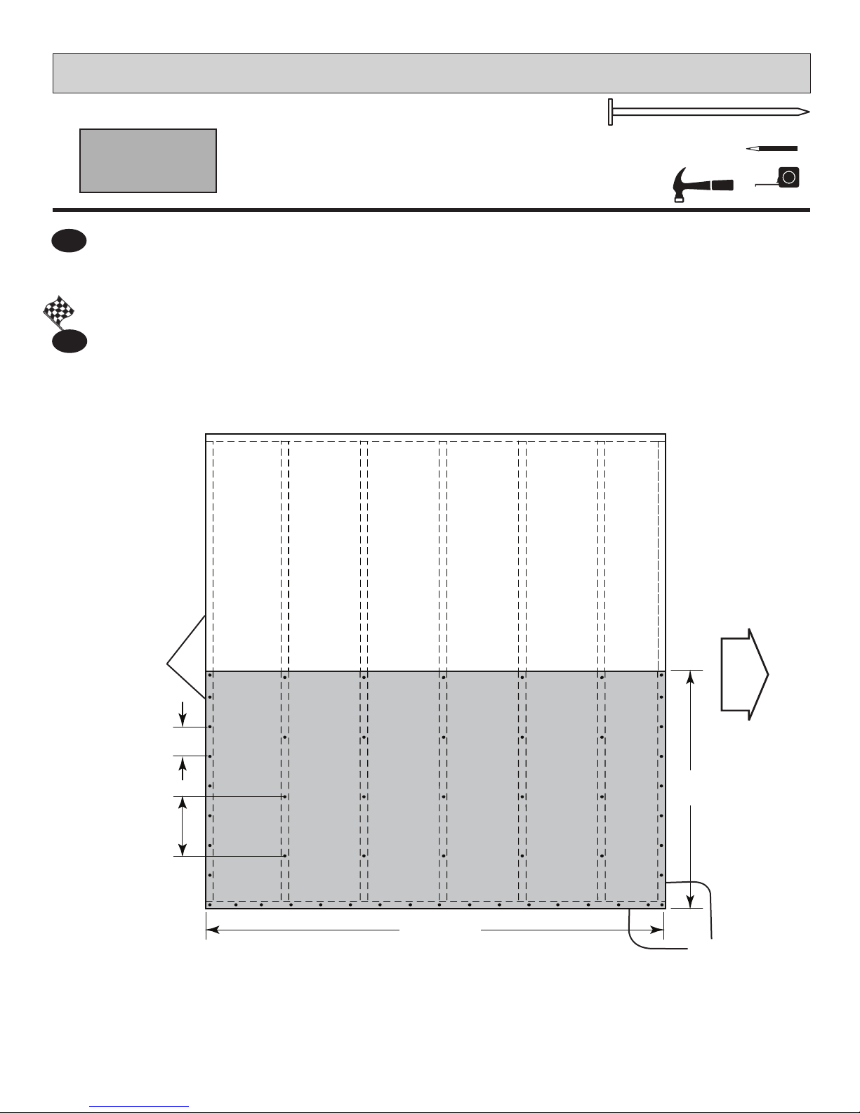
IMPORTANT!
IMPORTANT!
Check the oor frame is level after installing oor panels. Re-level if needed.
HINT:
BACKWALL
DOOR
• The oor should be used as a stable work surface for wall construction.
• Organize your assembly procedure during the build process
to avoid over-handling of the walls.
SIDEWALL
SIDEWALL
DOOR
FRONTWALL
12
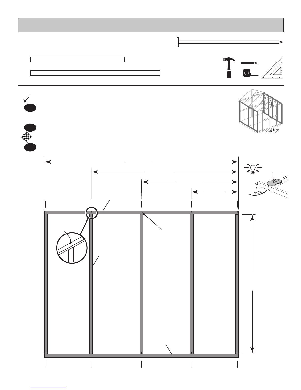
BEGIN
SIDE WALL FRAMES
PARTS REQUIRED:
x10
x4
FZ
2 x 3 x 66-1/2 " (5,1 x 7,6 x 168,9 cm)
PNA
2 x 3 x 92-1/2" (5,1 x 7,6 x 235 cm)
Orient parts on edge on oor. Measure and mark from end of boards.
1
IMPORTANT! You will build two walls the same.
2
Use two 3" nails at each mark.
FINISH
3
You have nished building one side wall frame. Proceed to attach wall panels.
PNA
92-1/2"
(235 cm)
x40
70-1/4"
(178,5 cm)
46-1/4"
(117,5 cm)
3" (7,6 cm)
HINT:
22-1/4"
(56,7 cm)
3" (7,6 cm)
Nails
Center on
marks.
FZ x5
66-1/2"
(168,9 cm)
PNA
13
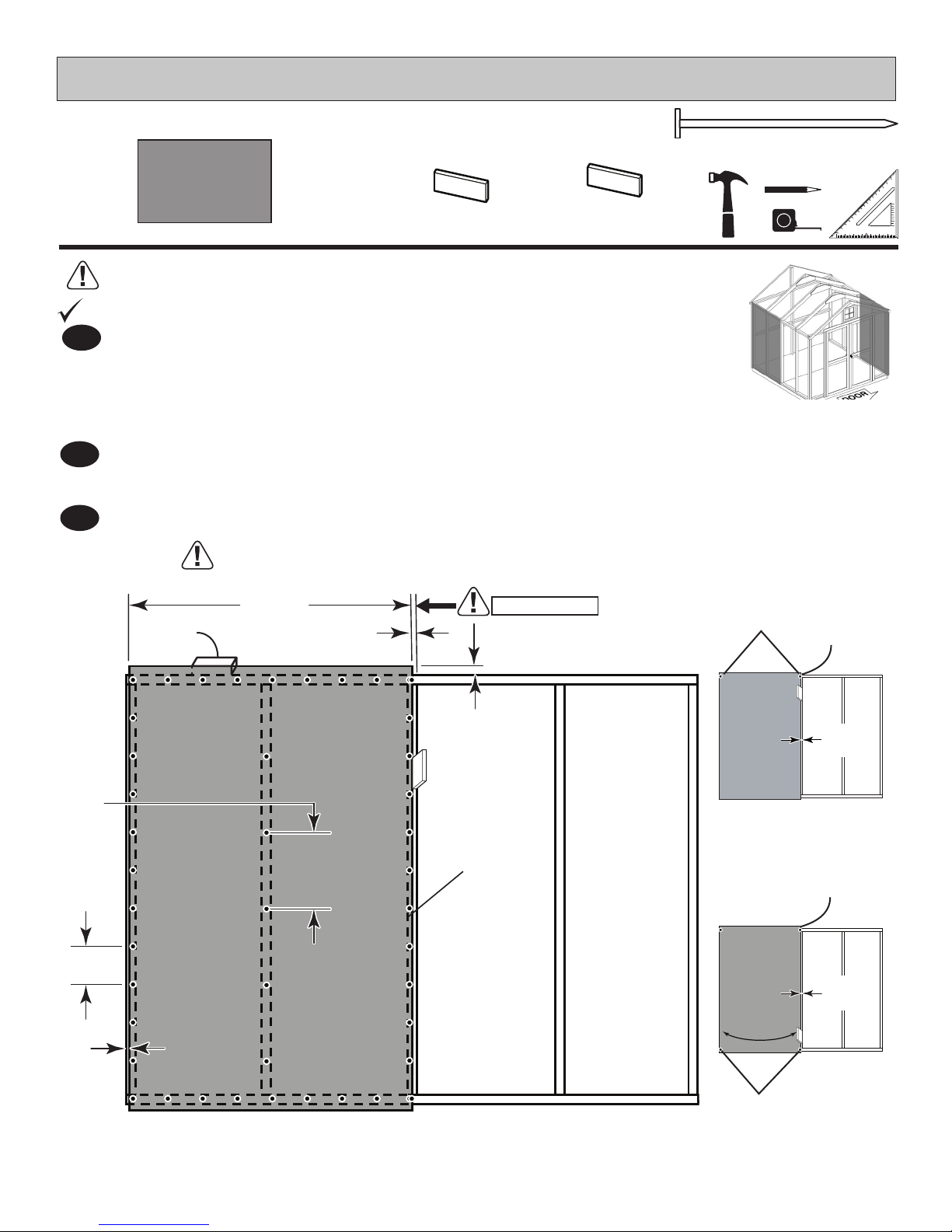
SIDE WALL PANELS
BEGIN
PARTS REQUIRED:
x2
3/8 x 46-1/8 x 72" (1 x 117,2 x 182,8 cm)
Ensure your wall frame is square by installing one panel and squaring frame.
1
Place a 46-1/8 x 72" panel onto wall frame with primed side up as shown.
Locate the panel 1-1/2" above the top plate. Use a DQ as a gauge block for
the 1-1/2" top overhang measurement. Use the GAA gauge block to mark
the 3/4" side measurement on the wall stud. Secure panel with two 2" nails
in the corners (Fig. A).
2
Move to the opposite end. Using the long edge of the panel as a lever, move
the panel side-to-side until you have a 3/4" measurement on the wall stud.
Secure corner with two 2" nails (Fig. B).
3
Nail the panel using 2" nails 6" apart on edges and 12" apart inside panel.
For squareness maintain 3/4" and
1-1/2" measurement along panel edge.
GAA
3/4"
GAUGE BLOCK
x90
DQ
2x3"
GAUGE BLOCK
2" (5,1 cm)
12"
(30,5 cm)
6"
(15,2 cm)
Panel
will be
back from
frame
about 1/8"
2 x 3"
46-1/8 "
(117,2 cm)
3/4"
(1,9 cm)
BEGIN HERE
1-1/2"
(3,8 cm)
3/4" Gauge
Block
Primed side UP
2 Nails
2 Nails
1-1/2"
(3,8 cm)
Overlap
3/4"
(1,9 cm)
Fig. A
1-1/2"
(3,8 cm)
Overlap
3/4"
(1,9 cm)
Fig. B
14
 Loading...