

Page 1
Models:
RH-36 Series
RH-42 Series
Wood Burning Fireplace
Owner’s Manual
Installation and Operation
DO NOT DISCARD THIS MANUAL
• Important operating
and maintenance
instructions included.
• Read, understand
and follow these
instructions for safe
installation and
operation.
WARNING
If the information in these instructions is not followed exactly, a
fi re may result causing property
damage, personal injury, or death.
• Do not store or use gasoline or other fl am-
mable vapors and liquids in the vicinity of
this or any other appliance.
• Do not overfi re. Overfi ring will void your
warranty.
• Comply with all minimum clearances to
combustibles as specifi ed. Failure to
comply may cause house fi re.
NOTICE
DO NOT
DISCARD
• Leave this manual with
party responsible for
use and operation.
WARNING
HOT SURFACES!
Screen/mesh, glass doors
and other surfaces are hot
during operation AND cool
down.
Hot screen/mesh and glass doors will cause burns.
• DO NOT touch screen/mesh or glass doors until
cooled
• NEVER allow children to touch screen/mesh or glass
doors
• Keep children away
• CAREFULLY SUPERVISE children in same room as
fi replace.
• Alert children and adults to hazards of high
temperatures.
High temperatures may ignite clothing or other
fl ammable materials.
• Keep clothing, furniture, draperies and other
fl ammable materials away.
Installation and service of this fi replace
should be performed by qualifi ed personnel.
Hearth & Home Technologies suggests NFI
certifi ed or factory-trained professionals, or
technicians supervised by an
NFI certifi ed professional.
Heat & Glo • RH-36/RH-42 • 4044-153 • Rev W • 11/08
WARNING
Fire Risk
• For use with solid wood fuel or decorative
gas appliance only.
• DO NOT install unvented gas logs.
1
Page 2
Read this manual before installing or operating this fi replace.
Please retain this owner’s manual for future reference.
Congratulations!
Congratulations on selecting a Heat & Glo wood burning
fi replace. The Heat & Glo fi replace you have selected is
designed to provide the utmost in safety, reliability and
effi ciency.
As the owner of a new fi replace, you’ll want to read and
carefully follow all of the instructions contained in this
owner’s manual. Pay special attention to all cautions and
warnings.
This owner’s manual should be retained for future reference. We suggest you keep it with your other important
documents and product manuals.
The information contained in this owner’s manual unless
noted otherwise, applies to all models and gas control
systems.
Your new Heat & Glo wood burning fi replace will give you
years of durable use and trouble-free enjoyment. Welcome to the Heat & Glo family of fi replace products!
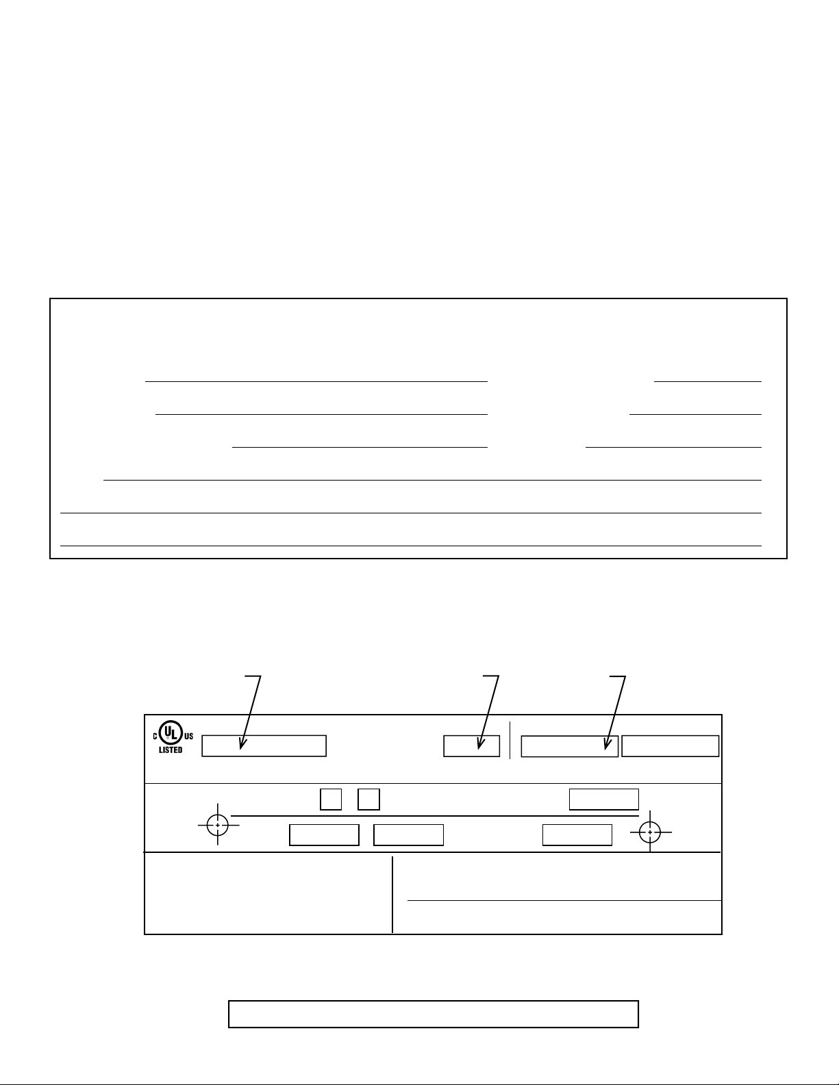
Homeowner Reference Information
We recommend that you record the following pertinent
information about your fi replace:
Model Name: Date purchased/installed:
Serial Number: Location on fi replace:
Dealership purchased from: Dealer phone:
Notes:
Listing Label Information/Location
The model information regarding your specifi c fi replace can be found on the rating plate located on the smoke shield of
the fi replace.
Serial
Number
Grate
Fireplace
Model
FIREPLACE NO.
FIRECHAMBER INTENDED FOR USE WITH HEARTH & HOME TECHNOLOGIES INC. LISTED FIREPLACE PARTS. SEE INSTALLATION AND
OPERATING INSTRUCTIONS FOR THIS MODEL. ONLY HEARTH & HOME TECHNOLOGIES INC. GLASS DOOR KITS CAN BE INSTALLED ON THIS UNIT.
FIREPLACE ALSO FOR USE
IN MANUFACTURED HOMES
FAN KIT
MODEL NO.
DO NOT OVERFIRE. USE ONLY: SOLID WOOD FUEL OR
LISTED DECORATIVE GAS APPLIANCE. DO NOT USE A
FIREPLACE INSERT OR OTHER PRODUCTS NOT
SPECIFIED FOR USE WITH THIS PRODUCT. IF DOORS
ARE USED OPERATE FIREPLACE WITH DOORS FULLY
OPEN OR CLOSED ONLY. WHEN BURNING A
DECORATIVE GAS APPLIANCE IN THE FIREPLACE,
ADJUST DAMPER TO THE FULLY OPEN POSITION.
Note: An arrow ( ) found in the text signifi es change in content.
2
Heat & Glo • RH-36/RH-42 • 4044-153 • Rev W • 11/08
WARNING: RISK OF
FIRE DAMAGE. REPLACE
GRATE WITH HEARTH & HOME
TECHNOLOGIES INC.
YES
NO
Î
&
MODEL NO.
CLEARANCE TO
COMBUSTIBLES:
WARNING! THIS FIREPLACE HAS NOT BEEN TESTED WITH AN UNVENTED
GAS LOG SET. TO REDUCE THE RISK OF FIRE OR INJURY, DO NOT
INSTALL AN UNVENTED GAS LOG SET INTO FIREPLACE.
WARNING! THIS APPLIANCE IS NOT FOR USE AS COOKING EQUIPMENT.
IF INSTALLATION OR OPERATING INSTRUCTIONS ARE MISSING
CONTACT: HEARTH & HOME TECHNOLOGIES INC.,
1915 W. SAUNDERS ST., MT. PLEASANT, IA 52641.
CHIMNEY
2 IN. MIN.
RATED AT
115 VOLTS, 50/60 Hz.,
MODEL NO.
FIREBOX
MFG. DATE
AMP.
IN.
MIN.
Page 3

Safety Alert Key:
!
• DANGER! Indicates a hazardous situation which, if not avoided will result in death or serious injury.
• WARNING! Indicates a hazardous situation which, if not avoided could result in death or serious injury.
• CAUTION! Indicates a hazardous situation which, if not avoided, could result in minor or moderate injury.
• NOTICE: Indicates practices which may cause damage to the fi replace or to property.
Table of Contents
Congratulations! 2
Warranty 4
1 Listing and Code Approvals 6
A. Appliance Certifi cation 6
B. Non-Combustible Materials 6
C. Combustible Materials 6
User Guide
2 Operating Instructions 7
A. Your Fireplace 7
B. Seasoned Wood 8
C. Starting a Fire 8
D. Grate 8
E. Firescreen 8
F. Flue Damper 8
G. Refractory 8
H. Glass Doors 9
I. Outside Air (optional) 9
J. Vented Gas Log Sets & Gas Log Lighters 9
K. Optional Components 9
L. Clear Space 9
M. Wood Fuel 10
3 Maintainance and Service 11
A. Disposal of Ashes 11
B. Chimney Inspection/Cleaning 11
C. Check Firebox Refractory 12
D. Inspect Grate 12
E. Glass Cleaning 12
4 Troubleshooting Guide 13
Installer Guide
5 Getting Started 14
B. Design and Installation Considerations 15
C. Draft 15
D. Negative Pressure 15
E. Locating Fireplace & Chimney 16
F. Tools and Supplies Needed 17
G. Fireplace System Requirements 17
H. Inspect Fireplace and Components 17
6 Framing & Clearances 18
A. Select Fireplace Location 18
B. Clearances 19
C. Sidewalls/Surrounds 20
D. Frame the Fireplace 20
7 Installation of Fireplace 21
A. Things to Consider 21
B. Position the Fireplace 21
C. Place Protective Metal Hearth Strips 21
D. Level Fireplace 21
E. Install Outside Air Kit 23
8 Chimney Assembly 24
A. Chimney Requirements 25
B. Using Offsets/Returns 26
C. Assemble Chimney Sections 27
D. Install Chimney Air Kit 27
E. Install Ceiling Firestops 28
F. Install Attic Insulation Shield 29
G. Cut out Hole in Roof 30
H. Complete Installation 30
I. Install Flashing 30
J. Chimney Termination Requirements 31
9 Chase Installations 32
A. Construct the Chase 32
B. Install Fireplace & Chimney 33
C. Install Chase Top 33
D. Install Termination Cap 34
10 Shrouds 36
A. Radiation Shield 36
B. Field Constructed Shrouds 36
11 Finishing 38
A. Non-Combustible Materials 38
B. Combustible Materials 38
C. Hearth Extension 38
D. Finishing Material 41
E. Combustible Mantel 42
F. Sidewalls/Surrounds 43
12 Accessories 44
A. Gas Log/Lighter Provision 44
B. Wood Burning Inserts 44
13 Reference Materials 45
A. Fireplace Dimensions 45
B. Optional Components 46
C. Chimney Components 47
D. Service Parts 50
E. Contact Information 52
Heat & Glo • RH-36/RH-42 • 4044-153 • Rev W • 11/08
3
Page 4
Î
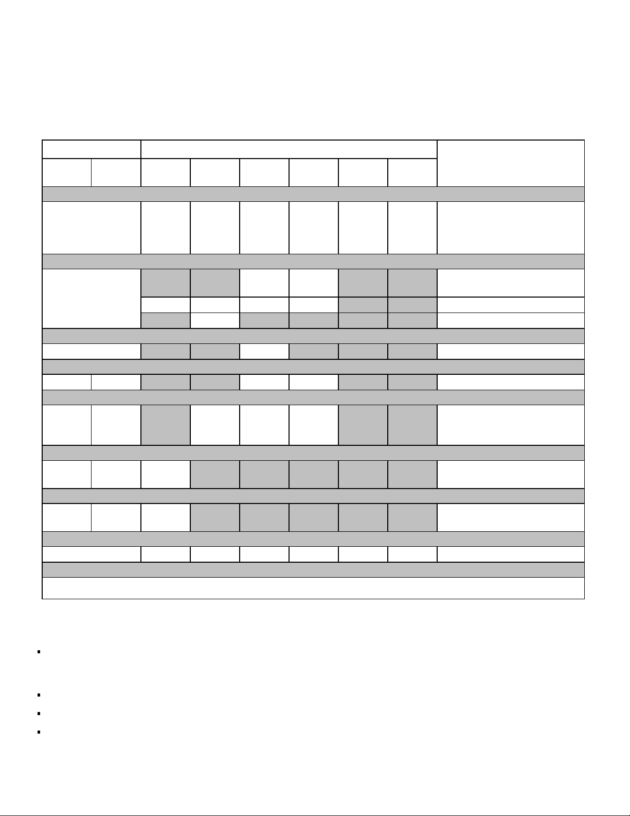
Warranty
Hearth & Home Technologies LIMITED WARRANTY
Hearth & Home Technologies (“HHT”) and its respective brands extends the following warranty for HHT gas, wood,
pellet and electric appliances purchased from an authorized HHT dealer and installed in the United States of America or
Canada. Warranty starts with date of purchase by the original owner (End User) except as noted for replacement parts.
Warranty Period HHT Manufactured Appliances and Venting
Parts Labor Gas Wood Pellet
1Year XXXXXX
EPA
Wood
Electric Venting
Components Covered
All Parts and Material Except as
covered by Conditions, Exclu-
sion, and Limitations listed
XX
2years
7years 3years X X X
10
years
Limited
Lifetime
90Days XXXXXX AllReplacementParts
Igniters, Electronic Compo-
nents, and Glass
srewolBXXXX
stoperiFXsraey3
faB&sgnitsaCXXsraey3sraey5 ?es
Firebox, HHT Chimney, Termi-
nation & Heat
Exchanger
slenaPyrotcarfeRdedloMX
yrotcarfeR&sgoL,srenruBXraey1
regnahcxEtaeH&xoberiFXraey1
See Conditions, Exclusions, and limitations. 9-01-08
CONDITIONS, EXCLUSIONS & LIMITATION OF LIABILITY
This warranty applies to the original owner and is transferable up to two years from date of purchase to the new
homeowner, provided the purchase was made through an authorized dealer or distributor of HHT, and the appliance
remains in its original place of installation.
The maximum amount recoverable under this warranty is limited to the purchase price of the product.
In no event shall HHT be liable for any incidental or consequential damages caused by defects in the product.
Adjustments, regular maintenance, cleaning and temporary repairs, or the failure to duplicate the problem in the home
is not covered under this warranty.
4021-645A 09-01-08 Page 1 of 2
4
Heat & Glo • RH-36/RH-42 • 4044-153 • Rev W • 11/08
Page 5

This limited warranty does not extend to or include surface ?nish on the appliance or terminations, door gasketing, glass
gasketing, glass discoloration, ?rebrick, pellet logs, kaowool or other ceramic insulating materials. Rust and/or corrosion
on any of the metal surfaces, cast iron components, baf?es, ?repots, doors, or ?rebox area are not covered by this
warranty.
Noise resulting from minor expansion, contraction, or movement of certain parts is normal and complaints related to
this noise are not covered by this warranty.
HHT’s obligation under this warranty does not extend to damages resulting from: (1) installation, operation or
maintenance of the appliance not in accordance with the installation instructions; operating instructions and the
listing agent identi?cation label furnished with the appliance; (2) installation which does not comply with local building
codes; (3) shipping, improper handling, improper operation, abuse, misuse, accident or unworkmanlike repairs; (4)
environmental conditions, inadequate ventilation or drafting caused by tight sealing construction of the structure
or handling devices such as exhaust fans or forced air furnaces or other such causes; (5) use of fuels other than
those speci?ed in the operating instructions; (6) installation or use of components not supplied with the appliance or
any other components not expressly authorized and approved by HHT; and/or (7) modi?cation of the appliance not
expressly authorized and approved by HHT in writing.
This warranty does not apply to non-HHT venting components, hearth components or other accessories used in
conjunction with the installation of this product.
This warranty is void if the appliance has been over-?red or operated in atmospheres contaminated by chlorine,
?uorine, or other damaging chemicals the appliance is subject to prolonged periods of dampness or condensation, or
there is any damage to the appliance or other components due to water or weather damage which is the result of, but
not limited to, improper chimney or venting installation.
HHT’s liability under this warranty is limited to the replacement and repair of defective components or workmanship
during the applicable period. HHT may fully discharge all of its obligations under such warranties by repairing the
defective component(s) at HHT’s discretion. Shipping costs are not covered under this warranty.
Some states do not allow exclusions or limitation of incidental or consequential damages, so those limitations may not
apply to you. This warranty gives you speci?c rights; you may also have other rights, which vary from state to state.
EXCEPT TO THE EXTENT PROVIDED BY LAW, HHT MAKES NO EXPRESS WARRANTIES OTHER THAN THE
WARRANTY SPECIFIED HEREIN. THE DURATION OF ANY IMPLIED WARRANTY IS LIMITED TO DURATION OF
THE WARRANTY SPECIFIED ABOVE.
This Limited Warranty is effective on all HHT appliances sold after September 01, 2008 and supersedes any and all
warranties currently in existence.
If warranty service is needed, you should contact your installing dealer. If the installing dealer is unable to provide
necessary parts or components, contact the nearest authorized HHT dealer or supplier.
4021-645A 09-01-08 Page 2 of 2
Heat & Glo • RH-36/RH-42 • 4044-153 • Rev W • 11/08
5
Page 6

1
Listing and Code Approvals
1
A. Appliance Certifi cation
This fi replace system has been tested and listed in accor-
dance with UL 127 and ULC-S610 standards by Underwriters Laboratories Inc. for installation and operation in
the United States and Canada.
This fi replace may be installed in sleeping rooms EX-
CEPT in manufactured homes. If installed with a gas log
set, provisions for the National Fuel Gas Code must be
met.
This fi replace has been tested and listed for use with the
optional components specifi ed in this manual. These op-
tional components may be purchased separately and installed at a later date. Installation of an outside air kit will
require signifi cant reconstruction and is best if installed at
the time of fi replace installation.
Heat & Glo is a registered trademark of Hearth & Home
Technologies Inc.
WARNING! Risk of Fire! Hearth & Home Technologies
disclaims any responsibility for, and the warranty and
agency listing will be voided by the following actions.
DO NOT:
• install or operate damaged fi replace
• modify fi replace
• install other than as instructed by Hearth & Home
Technologies
• operate the fi replace without fully assembling all
components
• overfi re
• install an unvented gas log set
• install any component not approved by Hearth & Home
Technologies
• install parts or components not Listed or approved
Improper installation, adjustment, alteration, service or
maintenance can cause injury or property damage. For
assistance or additional information, consult a qualifi ed
installer, service agency or your dealer.
B. Non-Combustible Materials
• Materials which will not ignite and burn, composed of
any combination of the following:
- Steel - Iron
- Brick - Tile
- Concrete - Slate
- Glass - Plasters
• Materials reported as passing ASTM E 136, Standard
Test Method for Behavior of Metals, in a Vertical Tube
Furnace at 750° C
C. Combustible Materials
• Materials made of or surfaced with any of the following
materials:
- Wood - Compressed paper
- Plant fi bers - Plastic
• Any material that can ignite and burn; fl ame proofed or
not, plastered or un-plastered
NOTICE: This fireplace is tested and approved as a
decorative fi replace. It should not be factored as a primary
heat source in residential heating calculations.
6
Heat & Glo • RH-36/RH-42 • 4044-153 • Rev W • 11/08
Page 7
2
User Guide
Operating Instructions
2
WARNING
HOT SURFACES!
Glass and other surfaces are hot during operation AND cool down.
Hot glass will cause burns.
• DO NOT touch glass until it is cooled
• NEVER allow children to touch glass
• Keep children away
• CAREFULLY SUPERVISE children in same room as fi replace.
• Alert children and adults to hazards of high temperatures.
High temperatures may ignite clothing or other fl ammable materials.
• Keep clothing, furniture, draperies and other fl ammable materials away.
If you expect that children may come into contact with this fi replace, we recommend a barrier such as a decorative
screen. See your dealer for suggestions.
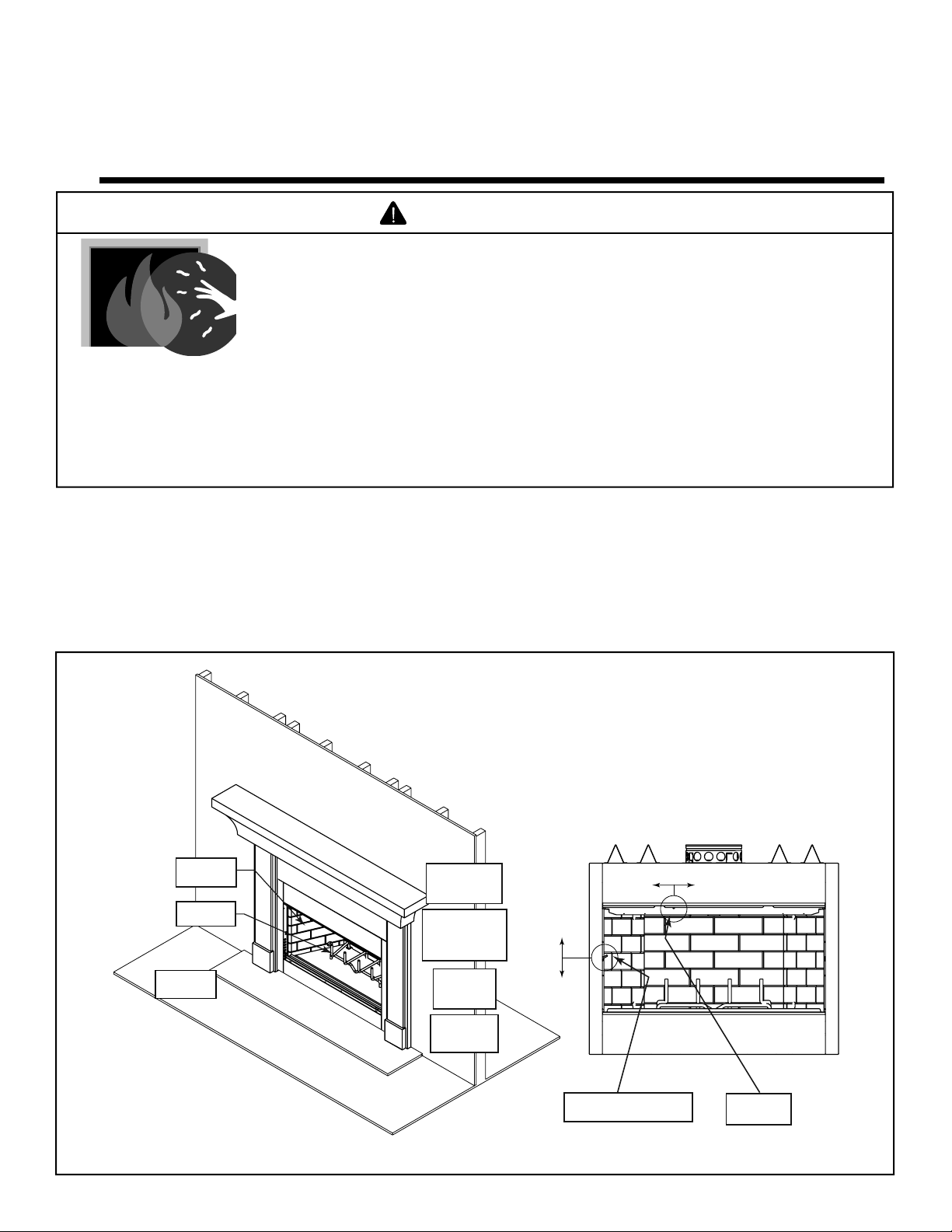
A. Your Fireplace
WARNING! DO NOT operate fi replace before reading and understanding operating instructions. Failure to operate fi replace
according to operating instructions could cause fi re or injury.
Mantel
Refractory
Section 2.G.
Grate
Section 2.D.
Wood Fuel
Section 2.M.
Hearth
Chimney
Air Kit Control
(not shown)
Gas Log Set
Gas Log Lighters
(not shown)
Section 2.J.
Firescreen
(not shown)
Section 2.E.
Glass Doors
(not shown)
Section 2.H.
Close
Open
Close
Open
Figure 2.1 General Operating Parts
Clear Space
Section 2.L.
Outside Air Control Handle
Section 2.I.
Heat & Glo • RH-36/RH-42 • 4044-153 • Rev W • 11/08
Flue Damper
Section 2.F.
7
Page 8

B. Seasoned Wood
Properly seasoned wood is important for successful
operation of your fi replace. Most woodburning fi replace
problems are caused by burning wet, unseasoned wood.
Seasoned fi rewood is wood that is cut to size, split and air
dried to a moisture content of around 20%.
Imagine a wooden bucket that weighs about eight
pounds. Fill it with a gallon of water, put it in the fi replace
and try to burn it. This sounds ridiculous but that is exactly
what you are doing if you burn unseasoned wood.
A tree cut down a year ago and not split is likely to have
almost as high a moisture content now as it did when it
was cut.
Please refer to Section 2.M for more detail.
C. Starting a Fire
NOTICE: You must establish a good draft to prevent smoke
spillage into the room.
WARNING! Risk of Fire! Keep combustible materials,
gasoline and other fl ammable vapors and liquids clear of
the fi replace.
DO NOT:
• store fl ammable materials close to the fi replace
• use gasoline, lantern fuel, kerosene, charcoal lighter
fl uid or similar liquids to start or “freshen up” a fi re in this
fi replace.
Keep all fl ammable liquids well away from the fi replace while
it is in use. Combustible materials may ignite.
D. Grate
This fi replace is designed to be used with the grate sup-
plied with this unit or one approved by HHT. The grate will
break down over time and will need occasional replacement.
WARNING! Risk of Fire!
integral grate.
• Keeps logs in place.
• Allows proper air circulation around the fi re.
Use only the factory-supplied
E. Firescreen
The fi rescreen is provided to control sparks. Keep it
closed when the fi replace is in use.
WARNING! Risk of Fire or Burns!
• Screen will not prevent burning materials from falling
out.
• Screen pulls or handles may be hot.
F. Flue Damper
• Refer to Figure 2.1 for location of control.
• Must be in fully open position (handle up toward the top
of the fi replace) during operation of the fi replace.
• Before lighting the fi replace, verify fully open position by
looking up from the inside of the fi replace.
WARNING! Risk of Fire and Asphyxiation! Open
damper prior to operating fi replace. A closed damper
overfi res the fi replace and spills smoke and fl ames
into the room.
• The fi rst three or four fi res should be of moderate size to
allow the oils and binders to be burned from the fi replace
and the refractory and paint to cure. You may notice
an industrial odor the fi rst few fi res. This is considered
normal.
• Use well-seasoned wood.
• Open the fl ue damper to a fully open position.
• Place crumpled or twisted paper under the fi replace
grate.
• Loosely arrange kindling or small pieces of wood to form
a ‘tent’ on the fi replace grate.
• Pre-warm the fl ue to establish a draft to help reduce
smoke spillage during start-up. Hold a rolled up piece
of burning newspaper under the fl ue damper for a few
moments.
• Light the crumpled paper to ignite the kindling.
• Add small pieces of wood until a hot bed of embers has
been established.
• Add a minimum of three average size pieces of split
fi rewood, placed to allow combustion air and fl ames
between them.
CAUTION! Odors and vapors released during initial
operation may be irritating to sensitive individuals.
Open windows for air circulation.
G. Refractory
• The refractory is supplied to contain heat and provide
an attractive interior.
• It will break down over time and will need occasional
replacement. Small hairline cracks and discoloration are
normal and do not affect its safety.
• (See refractory maintenance Section 3.C.)
WARNING! Risk of Fire! DO NOT burn fi replace with-
out refractory. Use only refractory supplied by Hearth &
Home Technologies, Inc.
8
Heat & Glo • RH-36/RH-42 • 4044-153 • Rev W • 11/08
Page 9
H. Glass Doors
• Glass doors are optional.
• Refer to Figure 2.2 for how to properly use them.
WARNING! Risk of Fire! Install ONLY doors ap-
proved by Hearth & Home Technologies, Inc.
WARNING! Risk of Fire and Smoke! Fireplaces
equipped with doors should be operated only with
doors fully open or doors fully closed. If doors are left
partly open, gas and fl ame may be drawn out of the
fi replace opening.
FULLY OPEN
CORRECT
PARTLY OPEN
INCORRECT
J. Vented Gas Log Sets & Gas Log Lighters
• Optional
• Vented gas logs or gas log lighters can be installed in
this fi replace. Follow the instructions provided with the
accessory for operation.
WARNING! Risk of Fire or Asphyxiation!
• DO NOT install unvented gas logs.
• Damper must be locked open.
• Gas fl ame may generate fumes.
K. Optional Components
• Other options may be available
• Consult your dealer/distributor
WARNING! Risk of Fire! DO NOT install and or use
any component not approved by Hearth & Home Technologies Inc.
FULLY CLOSED
CORRECT
Figure 2.2 Operating Positions of Bi-fold Doors
PARTLY CLOSED
INCORRECT
I. Outside Air (optional)
The outside air kit supplies some combustion air for your
fi replace. It may help reduce the effects of negative air
pressure. (See Section 5.D.)
• Refer to Figure 2.1 for location of control
• Close the inlet to prevent cold drafts when the fi replace
is not being used.
CAUTION! Risk of Burns! The outside air control
handle is HOT when fi replace is in operation. Adjust
BEFORE lighting fi re.
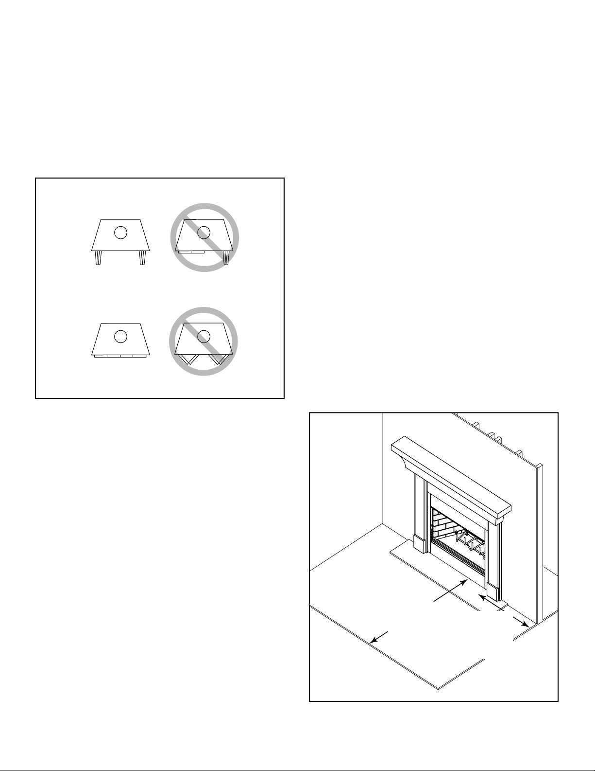
L. Clear Space
• Do not place combustible objects within areas indicated
in Figure 2.3.
WARNING! DO NOT place combustible objects in front
of the fi replace. High temperatures may ignite clothing,
furniture or draperies.
• Mantel - avoid placing candles and other heat-sensitive
objects on mantel or hearth. Heat may damage these
objects.
48 in. (1219 mm)
Clear Space
Front of Fireplace
Figure 2.3 Clear Space
Heat & Glo • RH-36/RH-42 • 4044-153 • Rev W • 11/08
12 in. (305 mm)
Clear Space
Sides of Fireplace
(from the FP
opening)
9
Page 10

M. Wood Fuel
Hardwood vs Softwood
Your fi replace performance depends on the quality of the
fi rewood you use.
• Seasoned wood contains about 8,000 BTUs per pound
.
• Hard woods are more dense than soft woods.
• Hard woods contain 60% more BTUs than soft woods.
• Hard woods require more time to season, burn slower
and are harder to ignite.
• Soft woods require less time to dry, burn faster and are
easier to ignite.
• Start the fi re with soft wood to bring the fi replace up to
operating temperature and to establish draft.
• Add hard wood for slow, even heat and longer burn
time.
Soft woods Hard woods
• Douglas Fir • Oak
• Pine • Maple
• Spruce • Apple
• Cedar • Birch
• Poplar
• Aspen
• Alder
Moisture
WARNING! Risk of Fire!
• DO NOT burn wet or green wood.
• Wet, unseasoned wood can cause accumulation of
creosote.
The majority of the problems fi replace owners experience
are caused by trying to burn wet, unseasoned wood.
• Wet, unseasoned wood requires energy to evaporate
the water instead of heating your home, and
• Evaporating moisture cools your chimney, accelerating
formation of creosote.
Seasoned Wood
• Cut logs to size
• Split to 6 in. (152 mm) or less
• Air dry to a moisture content of around 20%
- Soft wood - about nine months
- Hard wood - about eighteen months
NOTICE: Seasoning time may vary depending on drying
conditions.
Storing Wood
Steps to ensure properly seasoned wood:
• Stack wood to allow air to circulate freely around and
through woodpile.
• Elevate wood pile off ground to allow air circulation
underneath.
• Smaller pieces of wood dry faster. Any piece over 6 in.
(152 mm) in diameter should be split.
• Wood (whole or split) should be stacked so both ends
of each peice are exposed to air. More drying occurs
through the cut ends than the sides.
• Store wood under cover to prevent water absorbtion
from rain or snow. Avoid covering the sides and ends
completely.
WARNING! Fire Risk! DO NOT store wood:
• In front of the fi replace.
• In space required for loading or ash removal.
Processed Solid Fuel Firelogs
Manufactured fi relogs may be used with this fi replace.
Hearth & Home Technologies Inc. recommends the use of
UL Classifi ed processed fuel fi relogs. Follow the manufac-
turer’s lighting and safety instructions.
Using fi relogs may require more frequent chimney inspec-
tion and cleaning.
Do not poke or stir the logs while they are burning. Use
only fi relogs that have been evaluated for the application
in manufactured fi replaces and refer to fi relog warnings
and caution markings on packaging prior to use.
10
Heat & Glo • RH-36/RH-42 • 4044-153 • Rev W • 11/08
Page 11
3
Maintainance and Service
3
A. Disposal of Ashes
Frequency: When they reach bottom of grate
By: Homeowner
WARNING! Risk of Fire! Ashes could contain hot embers.
• Place ashes in a metal container with a tight-fi tting lid.
• The closed container should be placed on a
noncombustible fl oor or on the ground, well away from
all combustible materials, pending fi nal disposal.
• If the ashes are disposed of by burial in soil or otherwise
locally dispersed, they should be retained in the closed
container until all cinders have thoroughly cooled.
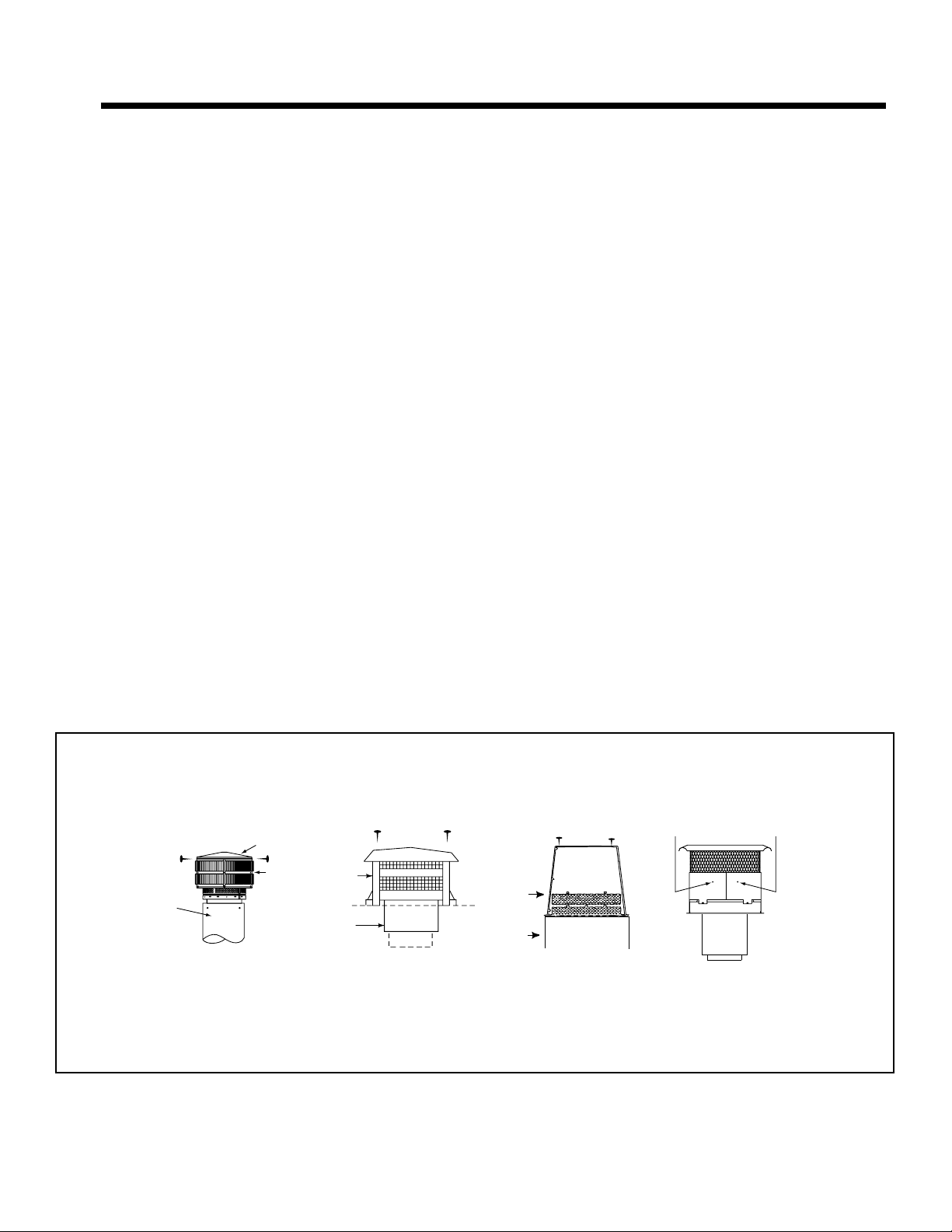
B. Chimney Inspection/Cleaning
Frequency: At least twice a year during heating season
or as recommended by a certifi ed chimney sweep
By: Certifi ed chimney sweep
WARNING! Risk of Fire! Ignited creosote is extremely
HOT. Prevent creosote buildup.
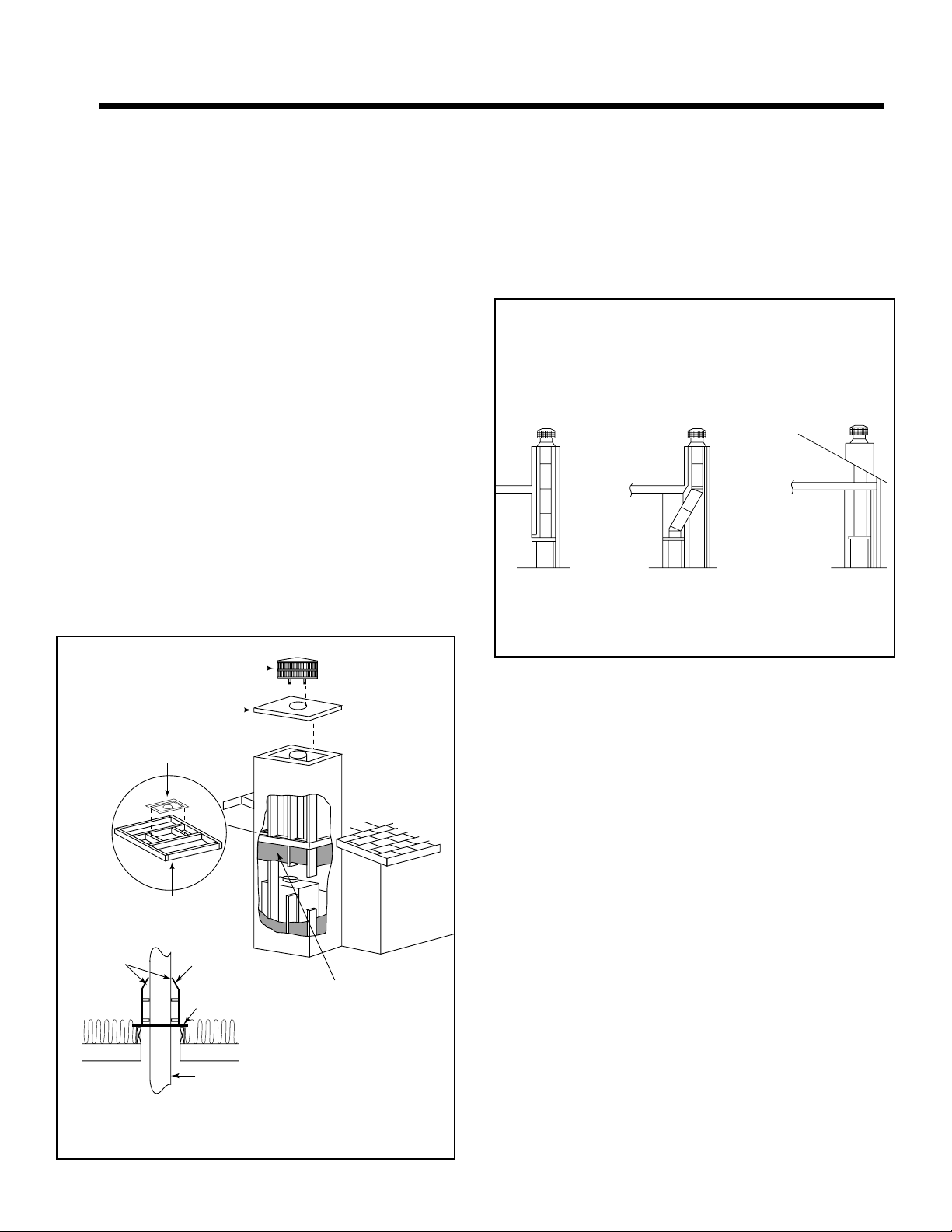
Refer to Figure 3.1 to remove/reinstall termination caps.
Creosote - Formation and Need for Removal
When wood is burned slowly, it produces tar and other
organic vapors, which combine with expelled moisture to
form creosote. The creosote vapors condense in the relatively cool chimney fl ue of a slow-burning fi re. As a result,
creosote residue accumulates on the fl ue lining. When
ignited this creosote makes an extremely hot fi re.
WARNING! Risk of Fire! A chimney fi re can permanently
damage your chimney system and nearby structures.
In the event of a chimney fi re, Hearth & Home Technolo-
gies Inc. recommends
• replacement of the chimney, and
• inspection of the adjacent structure to the provisions of
NFPA Level III inspection criteria.
The chimney shall be inspected at least twice a year
during the heating season to determine when a creosote
buildup has occurred.
When creosote has accumulated it shall be removed to
reduce the risk of a chimney fi re.
Remove screws,
lift top cover.
Top Cover
Cap
Chimney
TR344/TR342
Round
Termination Cap
Figure 3.1 Chimney & Termination Cap Cleaning
Cap
Slip
Section
Heat & Glo • RH-36/RH-42 • 4044-153 • Rev W • 11/08
Remove 4 screws
and lift top pan off.
ST375
Square
Termination Cap
1. Remove the 4 screws.
2. Remove the screen.
3. Remove the baffle.
Cap
Chase
TS345/TS345P
Square
Termination Caps
Remove 2 screws from
the front and back and
lift the top off.
TCT375
Terra Cotta
Termination Cap
11
Page 12

C. Check Firebox Refractory
Frequency: After each ash removal
By: Homeowner
WARNING! Risk of Fire!
Crumbling, deteriorated refractory can allow overheating
of surrounding materials.
Expansion and contraction will cause minor cracking of
the refractory. This is normal. The refractory will require
periodic replacement depending on use.
The panels should be replaced if
• Cracks exceed ¼ inch (6 mm) in width,
• Metal is exposed behind the refractory,
• Large pieces of refractory fall out.
Inspect fi replace refractory.
D. Inspect Grate
Frequency: After each ash removal
By: Homeowner
Inspect grate for:
• Warping or sagging 1-1/2 in. (38 mm) or more
• Broken welds
• Burn-through of grate bars
For safe operation, replace only with an approved grate
from Hearth & Homes Technologies Inc.
E. Glass Cleaning
Frequency: As desired
By: Homeowner
CAUTION! Handle glass assembly with care. Glass is
breakable.
• Avoid striking, scratching or slamming glass
• Avoid abrasive cleaners
• DO NOT clean glass while it is hot
Clean glass with a non-abrasive commercially available
cleaner or ashes:
• Light deposits
- Use household glass cleaner
• Heavy deposits
- Use wood ash on damp cloth or,
- Use commercial fi replace glass cleaner (consult with
your dealer)
12
Heat & Glo • RH-36/RH-42 • 4044-153 • Rev W • 11/08
Page 13
4
Troubleshooting Guide
4
Start Fire Problems Possible Cause Solution
Can’t get fi re started
Excessive smoke or spillage
Burns too slowly
Smolders, sizzles
Not enough kindling/paper or no
kindling/paper
Damper closed/not fully open Open damper.
Not enough air for fi re to ignite Check for restricted cap/shroud.
Wood condition is too wet, too
large
Use dry kindling, more paper. Arrange kindling &
wood for air movement.
Open air kit (if installed).
Check for fl ue blockage.
Pre-warm fl ue before starting fi re (refer to starting
fi re section).
Check for adequate vent height (refer to chimney
assembly section).
Open window below the fi replace towards the
wind.
Use dry, seasoned wood (refer to wood fuel
section).
Bed of coals not established
before adding wood
Flue blockage such as birds’
nests or leaves in termination
cap
Down draft or negative pressure
Competition with exhaust
devices
Fire burns too fast Extremely dry or soft wood Mix in hardwood.
No glass doors Add glass doors to slow down air fl ow.
Overdrafting Check for correct vent height; too much vertical
Start with paper & kindling to establish bed of
coals (refer to starting fi re section).
Have chimney inspected for creosote and cleaned
by a certifi ed chimney sweep.
Do not use exhaust fans during start-up (refer to
negative pressure section).
Open window below the fi replace towards the
wind.
Mix in less seasoned wood after fi re is established
(refer to wood fuel section).
height creates overdrafting.
Check location of vent termination (refer to
chimney assembly section).
Heat & Glo • RH-36/RH-42 • 4044-153 • Rev W • 11/08
13
Page 14
5
Getting Started
5
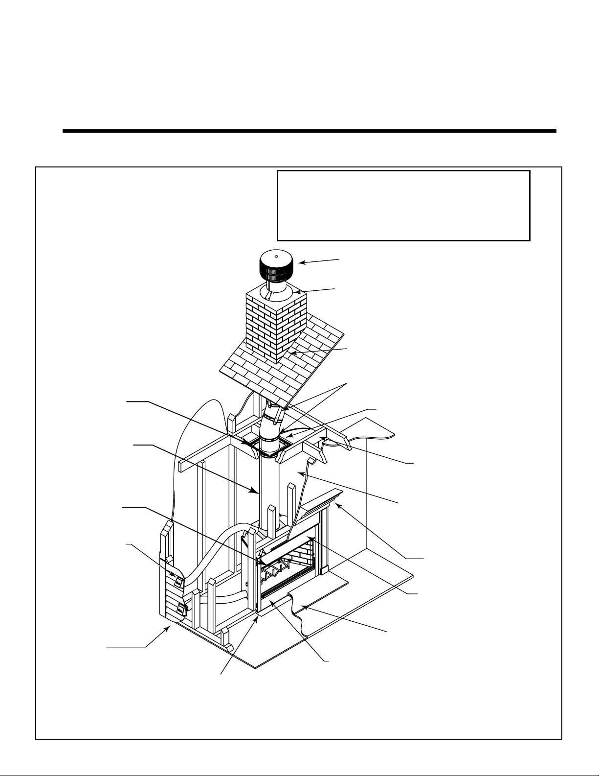
Installer Guide
Additional lateral
support for chimney
above roof (or enclosed
in chase) if needed
(Section 8.A.)
Non-combustible
roof flashing maintains
minimum clearance
around chimney
Support straps
on rafter support
chimney (not shown)
Ceiling firestop
on floor of attic
(Section 8.E.)
Chimney system
(Section 8)
Combustible framing/header
on top of V-shaped standoffs
(Section 6.D.)
Chimney Air Kit
(Section 8.D.)
Required in
Canada. Outlet
must be no
less than 6 ft.
(1.83m) off
ground level.
Outside
combustion air
(Section 7.E.)
Protective metal
hearth strip(s)
(Section 7.C.)
NOTICE:
• Illustrations and photos reflect typical installations
and are for design purposes only.
• Illustrations/diagrams are not drawn to scale.
• Actual product may vary from pictures in manual.
Termination cap
(Section 8.J. & 9.D.)
Storm Collar
(Section 8.H. & 9.C.)
Chimney penetrates roof
preferably without affecting
roof rafters (Section 8.E.)
Offset & Return (with hanger straps)
(Section 8.B.)
Attic insulation shield (not shown)
must be used here to keep
insulation away from chimney
if attic is insulated (Section 8.F.)
Framing headed off
in ceiling joists
(Section 8.E.)
Enclosed space above
and around fireplace
)
)
)
)
)
)
)))
)
)
)
)
)
)
)
)
)
)
)
)
)
)
)
)
)
)
)
)
)
)
)
)
)
)
)
)
)
)
)
)
)
)
)
)
)
)
)
)
)
)
)
)
)
)
)
)
)
)
)
)
(Section 6.B.)
Mantel and surround
(Section 11.E. & 11.F.)
Decorative facing
and trim
(Section 11.D.)
Hearth extension
(Section 11.C.)
Factory-built fireplace
Figure 5.1 Typical Fireplace System
14
Heat & Glo • RH-36/RH-42 • 4044-153 • Rev W • 11/08
Page 15

D. Negative PressureB. Design and Installation Considerations
NOTICE: Check building codes prior to installation.
• Installation MUST comply with local, regional, state and
national codes and regulations.
• Consult insurance carrier, local building inspector, fi re
offi cials or authorities having jurisdiction over restrictions,
installation inspection and permits.
Before installing, determine the following:
• Where the fi replace is to be installed
• The vent system confi guration to be used
• Gas supply piping
• Electrical wiring
• Framing and fi nishing details
• Whether optional accessories—devices such as a fan,
wall switch or remote control —are desired
NOTICE: Junction box should be installed during initial
setup to avoid major reconstruction.
C. Draft
Draft is the pressure difference needed to vent fi replaces
successfully. When a fi replace is drafting successfully, all
combustion byproducts are exiting the home through the
chimney.
Considerations for successful draft include:
• Preventing negative pressure
• Location of fi replace and chimney
NOTICE: Hearth & Home Technologies assumes no
responsibility for the improper performance of the fi replace
system caused by:
• Inadequate draft due to environmental conditions
• Downdrafts
• Tight sealing construction of the structure
• Mechanical exhausting devices
• Improper location of the chimney
WARNING! Risk of Asphyxiation! Negative pressure
can cause spillage of combustion fumes and soot. Fire
must draft properly for safe operation.
Negative pressure results from the imbalance of air available for the fi replace to operate properly. It can be stron-
gest in lower levels of the house.
Causes include:
• Exhaust fans (kitchen, bath, etc.)
• Range hoods
• Combustion air requirements for furnaces, water heaters
and other combustion appliances
• Clothes dryers
• Location of return-air vents to furnace or air
conditioning
• Imbalances of the HVAC air handling system
• Upper level air leaks such as:
- Recessed lighting
- Attic hatch
- Duct leaks
To minimize the effects of negative air pressure:
• Install the outside air kit with the intake facing prevailing
winds during the heating season
• Ensure adequate outdoor air for all combustion
appliances and exhaust equipment
• Ensure furnace and air conditioning return vents are not
located in the immediate vicinity of the fi replace
• Avoid installing the fi replace near doors, walkways or
small isolated spaces
• Recessed lighting should be a “sealed can” design
• Attic hatches weather stripped or sealed
• Attic mounted duct work and air handler joints and seams
taped or sealed
• Basement installations should be avoided
NOTICE: Hearth & Home Technologies Inc. recommends
the use of direct vent fi replaces in basements.
Heat & Glo • RH-36/RH-42 • 4044-153 • Rev W • 11/08
15
Page 16
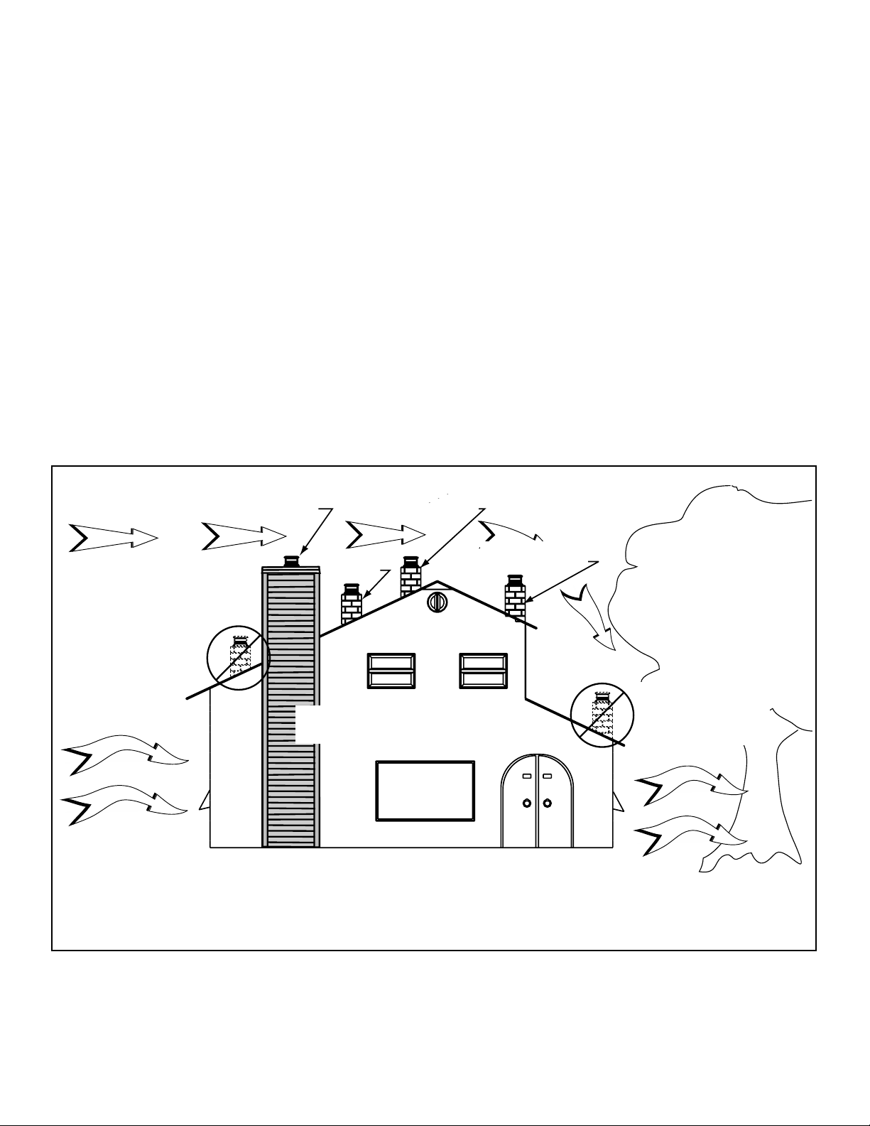
E. Locating Fireplace & Chimney
Location of the fi replace and chimney will affect perfor-
mance.
• Install within the warm airspace enclosed by the building
envelope. This helps to produce more draft, especially
during lighting and die-down of the fi re.
• Penetrate the highest part of the roof. This minimizes
the effects of wind loading.
• Locate termination cap away from trees, adjacent
structures, uneven roof lines and other obstructions.
• Minimize the use of chimney offsets.
• Consider the fi replace location relative to fl oor and ceiling
and attic joists.
• Take into consideration the termination requirements in
Section 8 and Section 9.
NOTICE: Locating the fi replace in a basement or in a location
of considerable air movement can cause intermittent smoke
spillage from fi replace. Do not locate fi replace near
• frequently open doors
• central heat outlets or returns
Location NOT recommended:
• Not the highest point of the roof
• Wind loading possible
Windward
Recommended Location:
• Above peak
Marginal Location:
• Below peak
Recommended:
• Insulated exterior chase
in cooler climates
Recommended Location:
• Above peak
• Inside heated space
Marginal Location:
• Wind loading possible
Location NOT recommended:
• Too close to tree
• Below adjacent structure
• Lower roof line
• Avoid outside wall
Leeward
Multi-level Roofs
Figure 5.2 Recommended Chimney Locations
16
Heat & Glo • RH-36/RH-42 • 4044-153 • Rev W • 11/08
Page 17

F. Tools and Supplies Needed H. Inspect Fireplace and Components
Before beginning the installation be sure the following
tools and building supplies are available:
Reciprocating saw Framing material
Pliers Non-combustible sealant
Hammer Gloves
Phillips screwdriver Framing square
Flat blade screwdriver Electric drill and bits
Plumb line Safety glasses
Level Tape measure
1/2-3/4 in. length, #6 or #8 self-drilling screws
Misc. screws and nails
G. Fireplace System Requirements
This fi replace system requires:
• Fireplace
• Hearth Refractory
• Grate Assembly
• Hearth Extension (required, sold separately)
• Chimney Air Kit (required in Canada)
• Chimney System (required, sold separately)
• Termination Cap (required, sold separately)
WARNING! Risk of Fire and/or Explosion! Damaged
parts could impair safe operation. DO NOT install damaged, incomplete or substitute components. Keep fi re-
place dry.
• Remove fi replace and components from packaging and
inspect for damage.
• Vent system components and doors are shipped in
separate packages.
• Report to your dealer any parts damaged in shipment.
• Read all the instructions before starting the
installation. Follow these instructions carefully
during the installation to ensure maximum safety
and benefi t.
Heat & Glo • RH-36/RH-42 • 4044-153 • Rev W • 11/08
17
Page 18

6
Framing & Clearances
6
A. Select Fireplace Location
G
F
A
B
In an exterior chase
C
A
Across a
corner
H
A
E
As a
room
divider
D
48 in.
(1219 mm)
minimum
or projecting into a
garage
Along a wall
B
A
I
H
Note:
1/2 in. (13 mm) min. air
space from fireplace to
combustible materials.
Note:
In addition to these
I
H
framing dimensions,
also reference the
following sections:
• Clearances (Section
6.B.)
• Mantel Projections
(Section 11.E.)
• Fireplace Dimensions
(Section 13.A.)
5/8 in. (16 mm) all
configurations
Note: Measurements are FRAMING dimensions only and do
not include drywall either in the cavity or on the interior walls.
Model A B C D E F G H I
RH-36
RH-42
Figure 6.1 Fireplace Locations (Framing dimensions shown)
18
inches 42 50 67 7/8 59 1/2 34 14 48 21 1/2 12 in. (305 mm)
mm 1067 1270 1724 1511 864 356 1219 546
inches 48 56 73 7/8 65 1/2 37 1/4 14 52 1/4 21 1/2
mm 1219 1422 1876 1664 946 356 1327 546
Heat & Glo • RH-36/RH-42 • 4044-153 • Rev W • 11/08
Minimum from FP
opening to any
perpendicular wall.
Page 19
B. Clearances
WARNING! Risk of Fire! You must comply with all minimum air space clearances to combustibles as specifi ed in Fig-
ure 6.2. DO NOT pack required air spaces with insulation or other materials.
Storm Collar
Roof Flashing
(roof)
Shaded areas
represent
2 in. (51 mm) min.
air space clearance
required around pipe
(insulation)
2 in. (51 mm) min.
Ceiling Firestop
48 in.
1219 mm
(attic)
Attic
Insulation
Shield
(ceiling)
Offset/Return (secured
with hanger straps)
(ceiling)
Must have 2 in. (51 mm)
minimum clearance
to header
0 in. to level
of standoffs
1/2 in. (13 mm) to back &
sides of appliance
0 in.
Combustible Object
Figure 6.2 Clearances to Combustible Materials
to floor
Note: Chimney air kit is not shown, but is required in Canada.
Heat & Glo • RH-36/RH-42 • 4044-153 • Rev W • 11/08
19
Page 20
C. Sidewalls/Surrounds
• Adjacent combustible sidewalls must be located a minimum of 12 in. (305 mm) from the fi replace opening.
• Combustible and noncombustible mantel legs, surrounds and stub walls may be constructed within the gridded area,
Figure 6.3.
4 in.
11 1/4 in.
[286 mm]
FLUSH
FRONT
A
50° angle
BRICK
FRONT
39° angle
[102 mm]
9 3/4 in.
[248 mm]
B
A
Fireplace
12 in.
[305 mm]
Figure 6.3 Mantel Leg or Wall Projections (Acceptable on both sides of opening)
12 in.
[305 mm]
Model #
RH-36
RH-42
D. Frame the Fireplace
Figure 6.4 shows typical framing using combustible materials (2x4 lumber shown).
• Observe all required air space clearances to combustible materials as shown in Figure 6.1 & 6.2.
• Framing across the top of fi replace must be above top standoffs.
Opening
in. 36 41
mm 914 1041
in. 42 47
mm 1067 1194
B
Outside Di-
mensions
2 in. (51 mm)
min. air space
clearance
from chimney.
C
B
Figure 6.4 Framing the Fireplace
20
Note: Framing must be
extended straight up,
all the way to the ceiling.
Header MUST NOT be notched!
D = extra space needed for outside air connection.
If outside air duct has no bend, this dimension may be
reduced as long as minimum clearances are met.
D
A
Model A B* C** D
RH-36
RH-42
* If interior of chase will be drywalled, add the thickness to
this measurement.
** Adjust header height for a raised fl oor under fi replace.
in. 42 21 1/2 39 3/4 8
mm 1067 546 1010 203
in. 48 21 1/2 39 3/4 8
mm 1219 546 1010 203
Heat & Glo • RH-36/RH-42 • 4044-153 • Rev W • 11/08
Page 21
7
Installation of Fireplace
7
CAUTION! Risk of Cuts/Abrasions. Wear protective
gloves and safety glasses during installation. Sheet metal
edges are sharp.
A. Things to Consider
• Location of chimney air kit (see Figure 7.4)
• Location(s) of outside air kit
• Electrical connections and/or wall switch
• Gas line piping
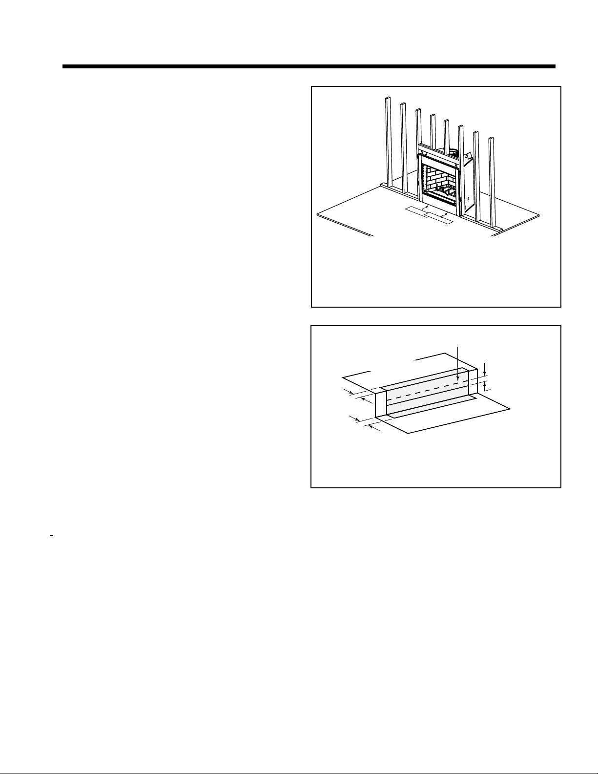
B. Position the Fireplace
• Place the fi replace on a continuous fl at surface.
• Follow framing instructions in Section 6.
WARNING! Risk of Fire! Prevent contact with sag-
ging, loose insulation.
• DO NOT install against vapor barriers or exposed
insulation.
• Secure insulation and vapor barriers.
• Provide minimum air space clearances at the sides
and back of the fi replace assembly as outlined in
Section 6.
Protective metal strips are placed 2 in. (51 mm) under the
front of the fireplace and must extend beyond the front
and sides of fireplace opening by 2 in. (51 mm)
Figure 7.1 Position the Protective Metal Hearth Strips
Top piece must overlap
bottom piece
Raised Platform
C. Place Protective Metal Hearth Strips
WARNING! Risk of Fire! Protective metal hearth strips
MUST be installed. DO NOT cover metal strips with combustible materials. Sparks or embers may ignite fl ooring.
• Refer to Figures 7.1 and 7.2.
• Locate the two protective metal hearth strips measuring
approximately 26 in. x 4 in. (660 mm x 102 mm) included
with this fi replace.
• Slide each metal strip 2 in. (51 mm) under front edge of
fi replace.
• Overlap strips in the middle of fi replace opening by 1 in.
(25 mm) minimum..
• Metal strips must extend beyond the front and sides of
the fi replace opening by at least 2 in. (51 mm).
• Protect the front of a platform elevated above the hearth
extension with metal strips (not included with fi replace)
per Figure 7.2. See Section 11 for hearth extension
instructions.
2 in.
(51 mm)
Floor
2 in.
(51 mm)
Figure 7.2 Protect the Front of an Elevated Platform
1 in. (25 mm) min.
overlap
D. Level Fireplace
• Level fi replace side-to-side and front-to-back.
• Shim with non-combustible material as necessary.
• Secure fi replace to framing with nailing fl anges with a
minimum of two fasteners per nailing fl ange.
• Check fi replace opening for square to ensure proper fi t
of glass doors. Measure diagonals of fi replace opening
to make sure they are equal.
Heat & Glo • RH-36/RH-42 • 4044-153 • Rev W • 11/08
21
Page 22
3 ft min. from
top of uppermost
chimney section
to air inlet.
)
)
)
)
)
)
)
)
)
)
)
)
)
)
)
)
)
)
)
)
)
)
))
)
)
))))
)))))))))))))))
)
)))))))))))))))))
)))))))
)
)
)
)
)
)
)
)
)
)
)
)
)
)
)
)
)
)
)
)
)
)
)
)
)
)
)
Note: Chimney air kit is
not shown, but is required
in Canada.
Figure 7.3 Possible Outside Air Inlet Locations
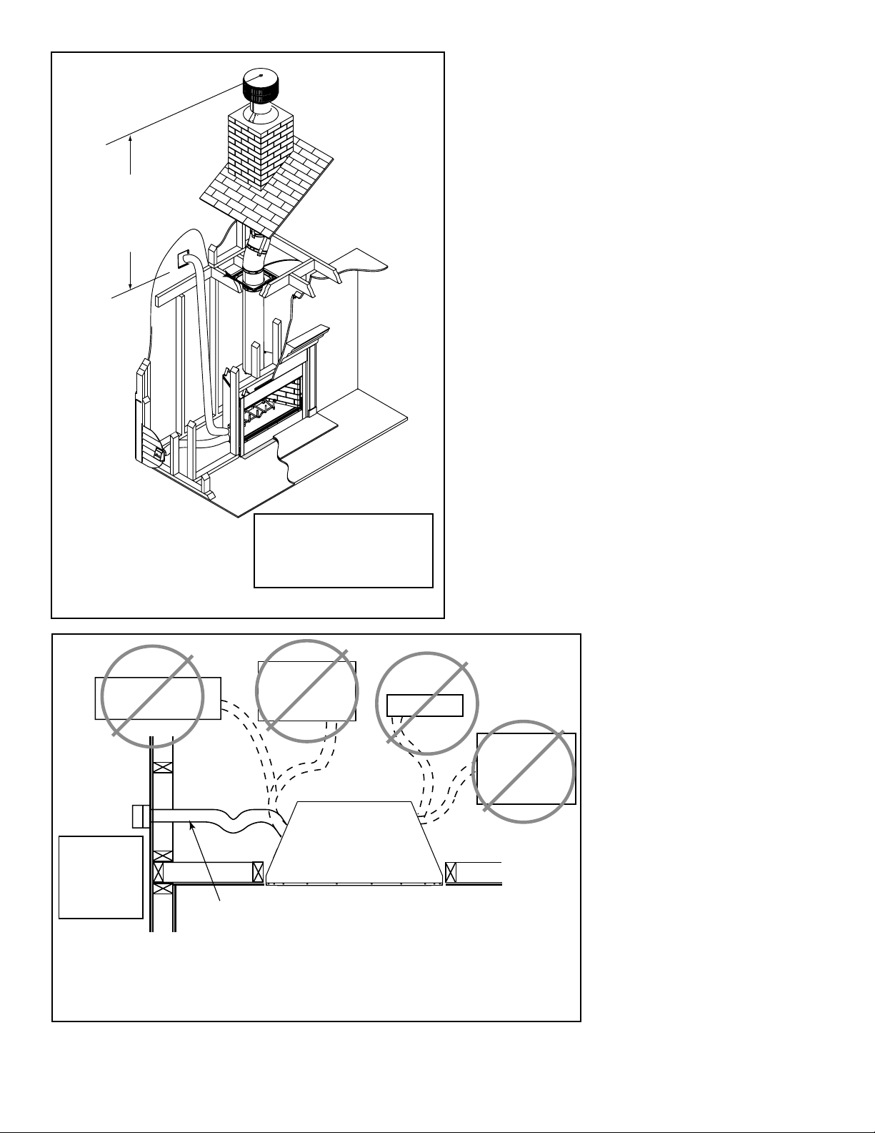
NO
NO
Outlet blocked by
snow, leaves, etc.
Garage or
combustible
liquids storage
YES
Clear area
outside
house or in
ventilated
crawl space
Use only duct materials specified
by manufacturer (preferably with
short run or mainly straight duct,
except small dip for cold air trap
which will help prevent flow of cold air).
Figure 7.4 Outside Combustion Air Placement
NO
Attic space
NO
Outlet placed
higher than 3 ft
below the
termination cap
Factory-built
fireplace
22
Heat & Glo • RH-36/RH-42 • 4044-153 • Rev W • 11/08
Page 23
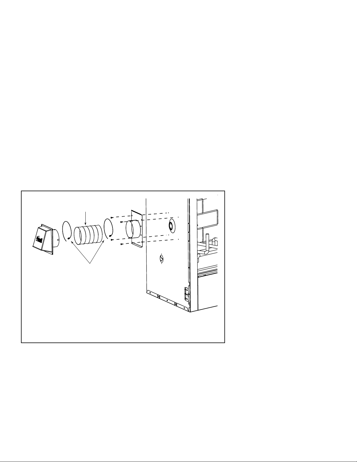
E. Install Outside Air Kit
• Optional.
• Keep duct runs short and straight to minimize restriction.
A small dip is acceptable for a cold air trap.
• The outside air kit must be installed on the left hand side
of the fi replace.
• Locate the outside air hood in a clear area, preferably
into prevailing wind during the heating season. Refer to
Figure 5.2.
• Install as shown in Figures 7.3, 7.4 and 7.5.
• The air duct may be run vertically.
• The outside air hood must be at least 3 ft (.91 m) below
the top of the uppermost chimney section.
CAUTION! Risk of Fire or Asphyxiation! DO NOT
draw outside combustion air from wall, fl oor or ceiling
cavity, or enclosed spaces such as an attic or garage.
• DO NOT place outside air hood close to exhaust
vents or chimneys. Fumes or odor could be drawn
into the room through the fi replace.
• Locate outside air inlet to prevent blockage from
leaves, snow/ice, or other debris. Blockages could
cause combustion air starvation.
Flexible Duct
(not supplied)
Outside Air
Hood
Figure 7.5 Outside Air Installation
2 Wire Ties
Outside Air
Plate
Assembly
Heat & Glo • RH-36/RH-42 • 4044-153 • Rev W • 11/08
23
Page 24
8
Chimney Assembly
8
NOTICE: Chimney performance may vary.
• Trees, buildings, roof lines and wind conditions affect
performance.
• Chimney height may need adjustment if smoking or
overdraft occurs.
Chimney must extend
beyond combustible
roof structure
Maintain minimum
height of chimney
above roof
Install roof flashing
according to minimum
requirements
Offsets/returns
may not exceed
30° from vertical
Lock chimney
sections together
firmly to resist
movement
Termination Cap
Additional
support for
tall chimneys
Storm Collar
Maintain minimum
clearances to
combustibles as
specified
Support straps for returns
must be secured to
adequate framing
Offsets and returns must
be secured with the screws
provided (outer pipe only)
24
Ceiling firestops
are required where
chimney passes
through ceiling or
floor
Figure 8.1 Typical Chimney System - Guidelines for Chimney System Installation
Heat & Glo • RH-36/RH-42 • 4044-153 • Rev W • 11/08
Page 25
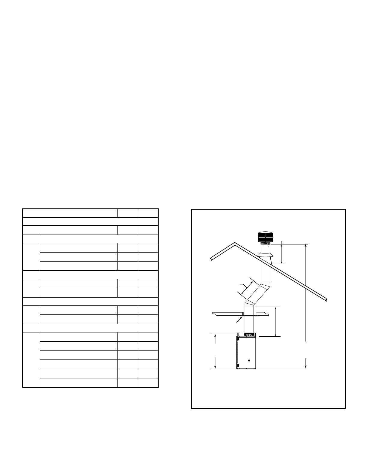
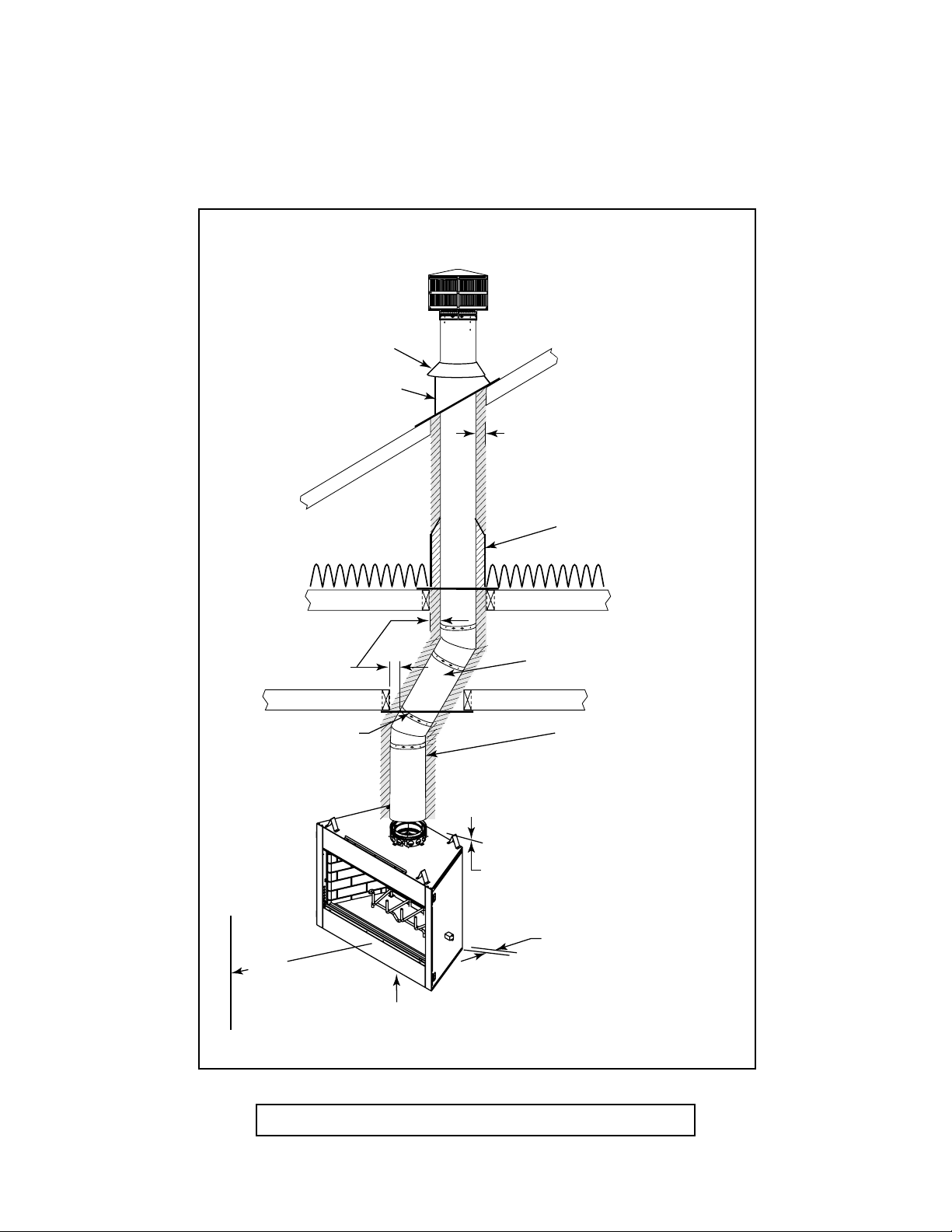
A. Chimney Requirements
Measure vertical distances from the base of the fi replace
as shown in Figure 8.2.
• Minimum overall straight height 13 (3.96 m)
• Minimum height with offset/return 14.5 ft (4.42 m)
• Maximum height 90 ft (27.43 m)
• Maximum chimney length between an offset
and return
• Maximum distance between chimney
stabilizers
• Double offset/return minimum height 20 ft (6.1 m)
• Maximum unsupported chimney length
between the offset and return
• Maximum unsupported chimney height above
the fi replace
• Maximum unsupported chimney above roof 6 ft (1.83 m)
20 ft (6.1 m)
35 ft (10.67 m)
6 ft (1.83 m)
35 ft (10.67 m)
WARNING! Risk of Fire! You must maintain 2 in. (51
mm) air space clearance to insulation and other combustible materials around the chimney system. Failure to do
so may cause overheating and fi re.
Table 8.1
Determine the chimney components needed to complete
your particular installation:
• Measure the total vertical height of the fireplace
installation from the base of the fi replace assembly to
the approximate location of the bottom of the termination
cap.
• Subtract the effective height of the fi replace assembly
(see Figure 8.2) from the total vertical height to determine
the overall height of the chimney installation.
• Create a schematic for your application similar to Figure
8.2 showing components required (referring to Table
8.1). Figure 8.1 identifi es those components and where
used.
• Install a ceiling fi restop whenever the chimney penetrates
a fl oor/ceiling.
NOTICE: A maximum of two pairs of offsets and returns
may be used.
CAUTION! Risk of Fire and/or Asphyxiation! DO
NOT connect this fi replace to a chimney fl ue servicing
another appliance. DO NOT connect to any air distribution duct or system. These actions could cause overheating/fi re in the chimney fl ue, or release of exhaust
fumes into the living areas.
HEIGHT OF CHIMNEY COMPONENTS in. mm
Chimney Stabilizer
SL3 4-3/4 121
Ceiling Firestops
FS338 0 0
FS339 0 0
FS340 0 0
Offsets/Returns
SL315 13-3/8 340
SL330 15-1/2 394
Roof Flashing
RF370 0 0
RF371 0 0
Chimney Sections*
SL306 4-3/4 121
SL312 10-3/4 273
SL318 16-3/4 425
SL324 22-3/4 578
SL336 34-3/4 883
SL348 46-3/4 1187
* Dimensions refl ect effective height.
20 ft (6.10 m) max.
pipe between an
offset & return
Ceiling Firestop
39 1/2 in. (1003 mm)
Effective Height
Figure 8.2 Chimney Requirements
14.5 ft (4.42 m) min. height/single offset-return
20 ft. (6.1 m) min. height/double offset-return
6 ft (1.83 m) max.
unsupported chimney
above roof
35 ft (10.67 m)
max. straight
unsupported
chimney height
90 ft (27.43 m) max. height
Heat & Glo • RH-36/RH-42 • 4044-153 • Rev W • 11/08
25
Page 26

B. Using Offsets/Returns
• Use an offset/return to bypass overhead obstructions.
• An offset and return can be used as a single entity or separated by chimney section(s).
WARNING! Risk of Fire! DO NOT use offset/returns greater than 30°. Chimney draft will be restricted and could cause
overheating and fi re.
• Measure the shift needed to avoid the overhead obstruction. Refer to dimension A in Figure 8.3.
• Find the appropriate A dimension listed in Table 8.2.
• The B dimension coinciding with the A dimension measurement in Table 8.2 represents the required vertical clearance
needed to complete the offset/return.
• Read across the chart to fi nd the number of chimney sections/model numbers needed between the offset and return.
A
Example:
Your “A” dimension from Figure 8.3 is 14 1/2 in. (368
mm). Using Table 8.2 the dimension closest to, but
not less than 14 1/2 in. (368 mm) is 14 1/2 in. (368
mm) using a 30° offset/return.
B
You determine from the table that you need 34 1/8 in.
(867 mm) (Dimension “B”) between the offset and
return.
1-1/4 in. (32 mm)
OVERLAP
Figure 8.3 Chimney Offset/Return
The chimney component that best fi ts your applica-
tion is one SL324.
Table 8.2
15-degree
A
Offset
in. mm in. mm in. mm in. mm
1-5/8 41 13-3/8 340 - -----3-5/8 92 15-1/2 394
2-7/8 73 17-3/4 451 1 -----5-1/2 140 18-5/8 473
4-1/8 102 22-3/8 568 2 -----7-1/4 184 21-3/4 552
4-1/2 114 23-5/8 600 - 1 - - - - 8-1/2 216 23-3/4 603
5-3/4 146 28-1/4 718 1 1 - - - - 10-1/4 260 27 686
6 152 29-3/8 746 - - 1 - - - 11-1/2 292 29 737
7-1/4 184 34 864 - 2 - - - - 13-1/4 337 32-1/8 816
7-3/4 197 36-1/8 918 - - - 1 - - 14-1/2 368 34-1/8 867
8-3/4 222 39-3/4 1010 1 - - 1 - - 16-1/4 413 37-3/8 949
10-3/8 264 45-5/8 1159 - - 2 - - - 19-1/4 489 42-1/2 1080
10-5/8 270 46-3/4 1187 - - - - 1 - 20-1/2 521 44-5/8 1133
11-7/8 302 51-3/8 1305 1 - - - 1 - 22-1/4 565 47-3/4 1213
13-1/2 243 57-1/4 1454 - - - 2 - - 25-1/4 641 52-7/8 1343
13-3/4 349 58-3/8 1483 - ----126-1/2 673 55 1397
15 381 63 1600 1 ----128-1/4 718 58-1/8 1476
16-1/2 419 68-3/4 1746 - 1 - - - 1 31-1/4 794 63-1/4 1607
18 457 74-5/8 1895 - - 1 - - 1 34-1/4 870 68-1/2 1740
19-5/8 498 80-3/8 2042 - - - 1 - 1 37-1/4 946 73-3/4 1873
20-5/8 524 84-1/8 2137 1 - - 1 - 1 39-1/8 994 76-7/8 1953
22-3/4 578 91-7/8 2334 - - - - 1 1 43-1/4 1099 84-1/8 2137
24 610 96-1/2 2451 1 - - - 1 1 45-1/8 1146 87-1/4 2216
25-7/8 657 103-1/2 2629 - ----249-1/4 1251 94-1/2 2400
Proper assembly of air-cooled chimney parts result in an overlap at chimney joints of 1-1/4 in. (32 mm). Effective length is built
into this chart.
B
Height
SL306 SL312 SL318 SL324 SL336 SL348
A
Offset
30-degree
B
Height
26
Heat & Glo • RH-36/RH-42 • 4044-153 • Rev W • 11/08
Page 27

C. Assemble Chimney Sections
WARNING! Risk of Fire! DO NOT install substitute or
damaged chimney components.
• Use only those components described in this manual.
Substitute or damaged chimney components could impair
safe operation and cause overheating and fi re.
• Support the pipe during construction and check to be
sure inadvertent loading has not dislodged the chimney
section from the fi replace or at any chimney joint.
• Attach a straight chimney section or an offset to the top
of the fi replace.
• Place inner fl ue to the inside of the chimney section below
it. Place the outer casing outside the outer casing of the
chimney section below it. Refer to Figure 8.4.
NOTICE: Chimney sections cannot be disassembled
once locked together. Plan ahead!
• Lock chimney sections and/or offsets/returns together by
pushing downward until the top section meets the stop
bead on the lower section.
• Pull on the top section to make sure it is fully engaged
and will not separate.
• You may use #6 or #8 sheet metal screws no longer than
1/2 in. (13 mm) to fasten chimney sections together. Do
NOT penetrate inner fl ue.
Figure 8.4 Assembling Chimney Sections
WARNING! Risk of Fire! You MUST use screws (pro-
vided) to fasten offset/returns to chimney sections to
keep the chimney parts from twisting. Failure to do so
could cause fi re.
• Fasten offset/returns to chimney sections. Insert the
screws (provided) through the predrilled holes. Do NOT
penetrate inner fl ue.
• Secure chimney returns with hanger straps provided;
fasten to studs or joists.
• Vertical straight runs of chimney must be supported every
35 ft (10.7 m).
D. Install Chimney Air Kit
• Required in Canada.
• Follow instructions provided with this accessory.
Heat & Glo • RH-36/RH-42 • 4044-153 • Rev W • 11/08
27
Page 28

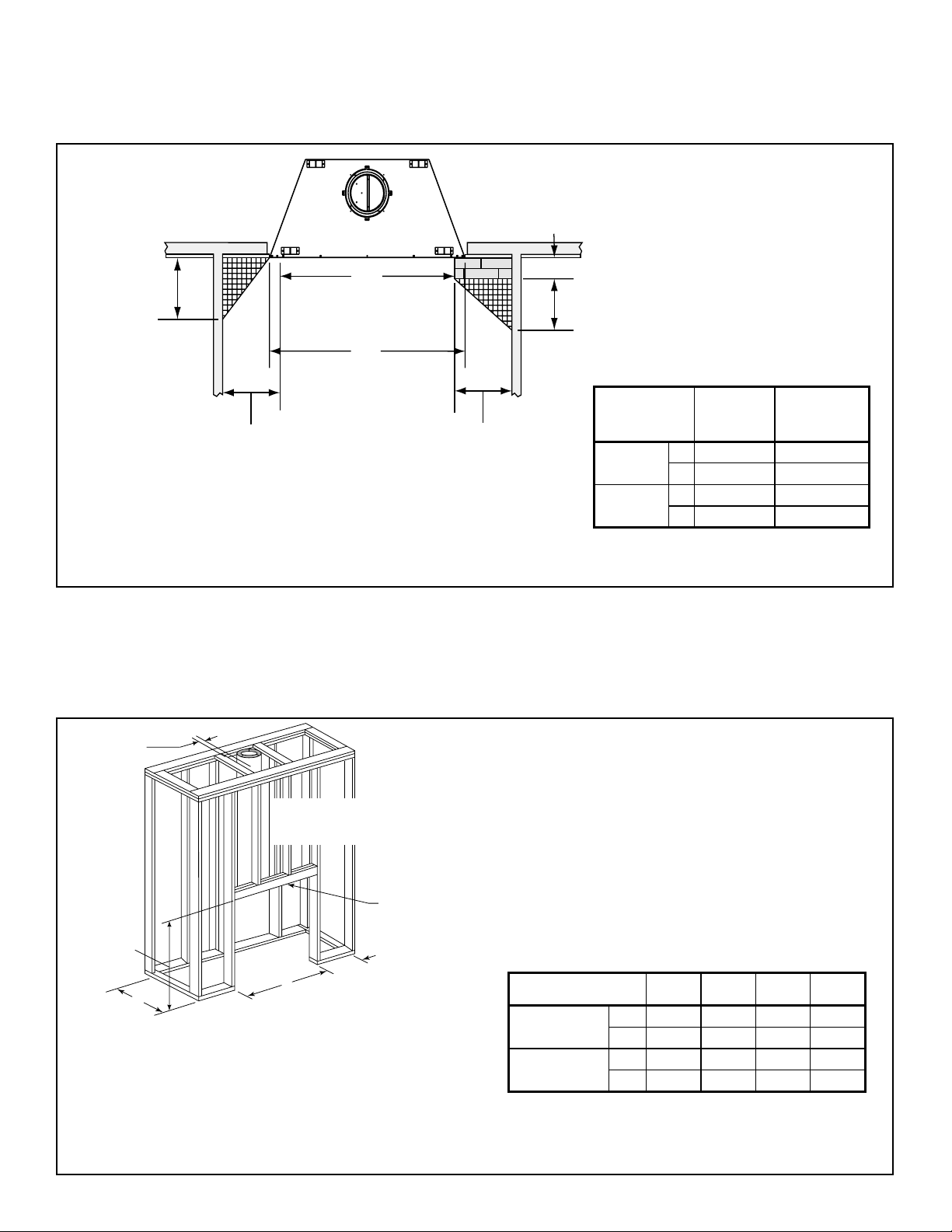
E. Install Ceiling Firestops
ROOM ABOVE (non-insulated ceiling)
CAUTION! Risk of Fire! Ceiling fi restops must be used
whenever the chimney penetrates a ceiling/fl oor.
• Chase construction requires ceiling fi restops at each
fl oor or every 10 ft (3.05 m) of clear space.
• The ceiling fi restop slows spread of fi re and reduces cold
air infi ltration.
• Install a ceiling fi restop whenever chimney penetrates
ceiling/fl oor.
• Mark and cut an opening in ceiling as shown in
Figure 8.5.
• Frame the opening with the same size lumber used in
the ceiling joists.
• Nail the ceiling fi restop to the bottom of the ceiling joists
when there is a room above.
• Use an attic insulation shield if the ceiling is insulated.
The ceiling fi restop may then be attached above or below
the joists.
WARNING! Risk of Fire! DO NOT seal area between
fi restop opening and chimney pipe except where they
enter the attic or leave the warm air envelope of the
home (use 600° F sealant).
B
A
Ceilng firestop from
bottom
ATTIC ABOVE (insulated ceiling)
Ceiling firestop from
top
Note:
Use same dimensional lumber for framing
ceiling firestop and joists.
AB
Catalog #
FS338 14-1/2 368 14-1/2 368 0°
FS339 14-1/2 368 18-3/8 467 15°
FS340 14-1/2 368 23 584 30°
Anglein. mm in. mm
Figure 8.5 Installing the Ceiling Firestop
28
Heat & Glo • RH-36/RH-42 • 4044-153 • Rev W • 11/08
Page 29

F. Install Attic Insulation Shield
WARNING! Risk of Fire! You MUST install an attic insulation shield when there is any possibility of insulation or
other combustible material coming into contact with the
chimney.
• DO NOT pack insulation between the chimney and the
attic insulation shield.
• Failure to keep insulation and other materials away from
chimney pipe could cause fi re.
• DO NOT offset chimney inside insulation shield.
Installation of a ceiling fi restop is required
• Refer to Figures 8.6 - 8.8.
• Roll the shield (around the chimney if already installed)
until you have a 3 in. (76 mm) overlap and the three
holes on each side match up (large holes on top).
• Insert three screws into the matching holes to form a
tube.
• Bend three tabs on the bottom of the tube inward to 90°
to maintain chimney air space (refer to Figure 8.6).
• Rest the insulation shield on the ceiling fi restop below.
• Bend the three short tabs at the top of the shield inward
to 90° to maintain the 2 in. (51 mm) air space from the
chimney.
• Bend the remaining top tabs to just meet the pipe.
Bend remaining tabs
to rest against pipe to
Bend inward
90°
prevent insulation
from falling in.
Insert three
3 in. (76 mm)
overlap
Figure 8.6 Prepare Attic Insulation Shield
Pipe
6 Tabs bent
in 90°
rest against pipe
screws
Tabs bent in to
Attic Insulation Shield
14-1/2 in. (368 mm)
diameter
Ceiling Firestop
If you wish to make a custom shield or barrier, follow
these guidelines:
• Metal is preferred, although any material stiff enough to
hold back the insulation can be used.
WARNING! Risk of Fire! Use of cardboard or other
materials that can defl ect under humidity or other envi-
ronmental conditions is not recommended.
• The shield or barrier must be tall enough to extend
above the insulation and prevent blown-in insulation
from spilling into the cavity.
• Maintain specifi ed air spaces around chimney.
• Check instructions and local codes for further details.
Insulation
10-1/2 in.
(267 mm)
Figure 8.7 Install Attic Insulation Shield (fi restop above ceiling)
10-1/2 in.
(267 mm)
Pipe
Pipe
6 Tabs bent
in 90°
Pipe
Insulation
Tabs bent in to
rest against pipe
Attic Insulation Shield
14-1/2 in. (368 mm)
diameter
InsulationInsulation
Ceiling Firestop
Figure 8.8 Install Attic Insulation Shield (fi restop below ceiling)
Heat & Glo • RH-36/RH-42 • 4044-153 • Rev W • 11/08
29
Page 30

G. Cut out Hole in Roof
• Refer to Figure 8.9.
• Plumb from roof to center of chimney.
• Drive a nail up through roof to mark center of pipe.
• Measure to either side of nail and mark the 14-1/2 in. x
14-1/2 in. (368 mm x 368 mm) opening required.
• Measure opening on the horizontal; actual length may
be larger depending on roof pitch.
• Cut out and frame opening.
• Refer to Chapter 25 of the Uniform Building Code for
roof framing details.
H. Complete Installation
WARNING! Risk of Fire! You MUST maintain 2 in.
(51 mm) air space to insulation and other combustible
materials around the chimney system. Failure to do so
could cause overheating and fi re.
• Keep chimney sections from separating or twisting.
• You may secure straight chimney sections at the joints
with screws no longer than 1/2 in. (13 mm).
The following steps should be skipped if using a
chase.
• Install roof fl ashing appropriate to roof pitch.
• Install round termination cap and storm collar.
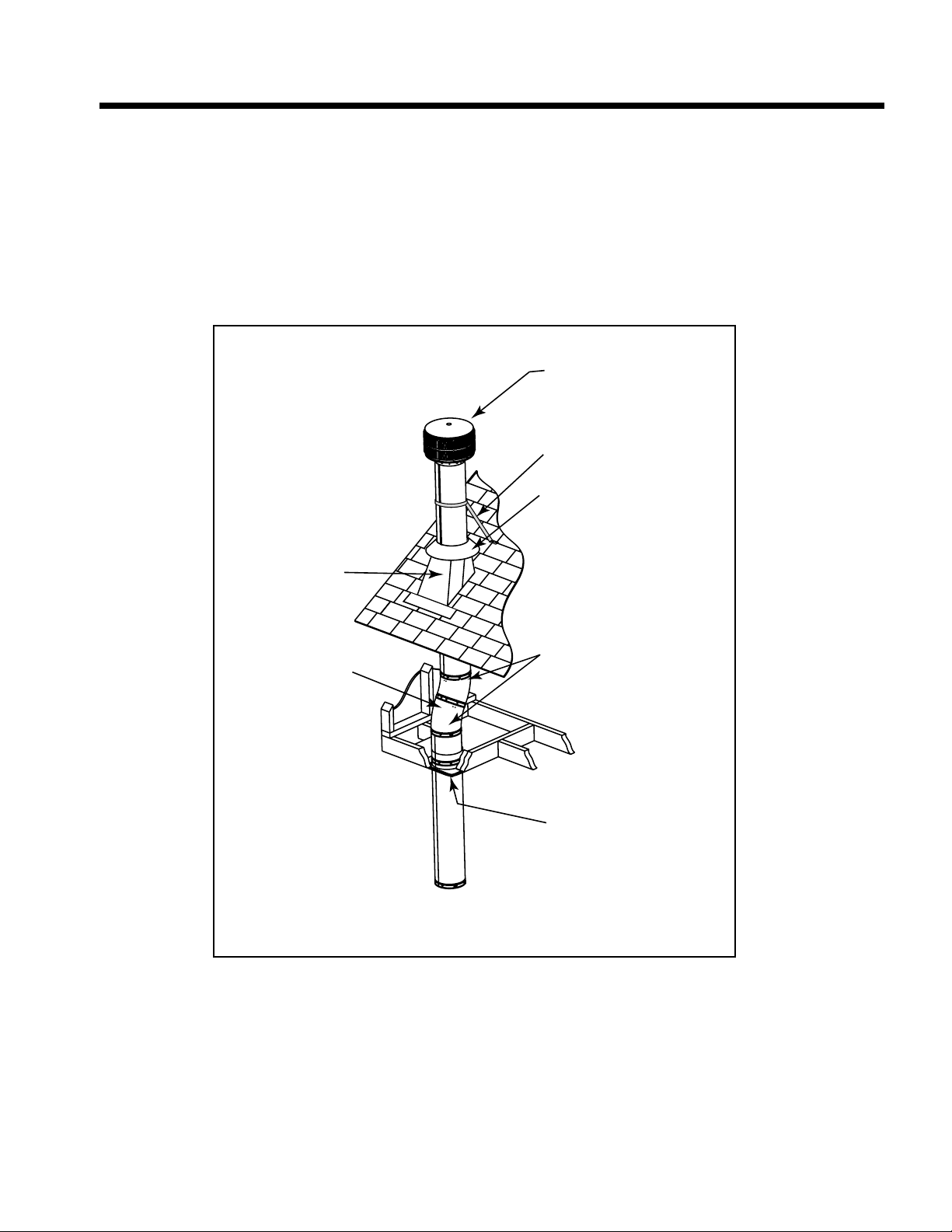
I. Install Flashing
• Assemble chimney so it passes through the framed
opening.
• Slip the fl ashing over the chimney.
NOTICE: Roofi ng shingles must be below the fl ashing
plate on the lower side of a sloped roof and over the
fl ashing plate on the sides and top.
• Nail the fl ashing to the roof. Keep gaps between the
fl ashing plate and the roof to a minimum.
• Caulk the fl ashing plate and roof junction as well as the
vertical seam on the fl ashing. All nail heads must be
caulked with a roofi ng sealant.
Figure 8.9 Ceiling/Attic Construction
30
Heat & Glo • RH-36/RH-42 • 4044-153 • Rev W • 11/08
Page 31

J. Chimney Termination Requirements
• Install a cap approved and listed for this fi replace system.
• Locate cap where it will not become plugged by snow or other materials.
• Locate cap away from trees or other structures.
• The bottom of the termination cap must be at least 3 ft (.91 m) above the roof AND at least 2 ft (.61 m) above any portion
of roof within 10 ft (3.05 m) as shown in Figure 8.10.
• The distance required between caps is shown in Figure 8.10.
Slanted Roofs
Chimney must extend 2 ft (.6 m)
Chimney must
extend 3 ft (.9 m)
above the roof
above any portion of the roof or
adjacent structures within
10 ft (3 m) of the chimney
Flat Roofs
Chimney must
extend 3 ft (.9 m)
above the roof
Multiple Chimney Locations
AB
6in.(minimum)upto20in.
152 mm/508 mm
20 in. and over 0 in. minimum
18 in. minimum
457 mm
Gas
Termination
Cap **
Chimney must extend 2 ft (.6 m)
above any portion of the roof or
adjacent structures within
10 ft (3 m) of the chimney
Gas, Wood or Fuel Oil
Termination Cap
B
A *
Wood
Minimum
(See
illustration
above)
Perpendicular Wall
Figure 8.10 Multiple Chimney Locations
Î
Ifusingdecorativecapcover(s),thisdistancemayneedtobe
*
increased. Refer to the installation instructions supplied with the
decorative cap cover.
In a staggered installation with both gas and wood terminations, the
**
wood termination cap must be higher than the gas termination cap.
Heat & Glo • RH-36/RH-42 • 4044-153 • Rev W • 11/08
31
Page 32
9
Chase Installations
9
A. Construct the Chase
A chase is a vertical boxlike structure built to enclose the
fi replace and/or its vent system. Vertical chimneys that
run on the outside of a building must be installed inside a
chase.
Construction of the chase may vary with the type of building. These instructions are not substitutes for the requirements of local building codes. Local building codes MUST
be checked.
A chase should be constructed in the manner of all
outside walls of the home to prevent cold air drafting
problems. The chase should not break the outside building envelope in any manner. All outer walls need to be
insulated.
Building codes require false ceiling and ceiling fi restops
at each fl oor of the chase or every 10 ft (3.05 m) of clear
space to control spread of fi re.
Walls, ceiling, base plate and cantilever fl oor at the fi rst
level of the chase should be insulated. See Figure 9.1.
Vapor and air infi ltration barriers should be installed in the
chase as per regional codes for the rest of the home. Additionally, Hearth & Home Technologies recommends that
the inside surfaces be sheet rocked and taped (or the use
of an equivalent method) for maximum air tightness.
Gas line holes and other openings should be caulked with
high temperature caulk or stuffed with unfaced fi berglass
insulation. If the fi replace is being installed on a cement
slab, we recommend that in cold climates, a sheet of
plywood or other raised platform be placed underneath to
prevent conducting cold up into the room.
Three examples of chase applications are shown in Figure 9.2.
1. Fireplace and chimney enclosed in an exterior chase.
2. Chimney offset through exterior wall and enclosed in chase.
3. Chase constructed on roof.
Note: In cooler climates, all chase walls should be insulated.
1 2 3
Round Termination Cap
Metal Chase Top
Firestop
False Ceiling
Tabs
Insulation
False Ceiling
Ceiling
Attic
Insulation
Shield
Ceiling
Firestop
Insulation
False Ceiling
Chimney
Insulation in the
outside walls
of the chase
Figure 9.2 Chase Constructions
WARNING! You must install false ceilings and ceiling
fi restops at each fl oor of the chase or every 10 ft (3.05 m)
to control spread of fi re.
WARNING! Risk of Fire! DO NOT seal area between fi re
stop opening and chimney pipe. Restricting air fl ow around
chimney may cause fi re.
WARNING! Risk of Fire! You must maintain a minimum
2 in. (51 mm) air space clearance to insulation and other
materials surrounding the chimney system.
• Insulation and other materials must be fi rmly secured to
prevent accidental contact with chimney system.
• The chase must be properly blocked to prevent blown
insulation or other combustibles from entering and
making contact with fi replace or chimney.
• Failure to prevent contact between insulation or other
materials and chimney system may cause overheating
and fi re.
Figure 9.1 Chase Assembly
32
Heat & Glo • RH-36/RH-42 • 4044-153 • Rev W • 11/08
Page 33

B. Install Fireplace & Chimney
Install as per Sections 7 and 8.
C. Install Chase Top
• You MUST use a chase top in a chase installation. Chase
tops are available from your Heat & Glo dealer or may
be fi eld constructed.
• Include a turndown and drip edge to prevent water from
seeping into the chase.
• Include a 2 in. (51 mm) soldered, caulked or spun collar
around pipe opening to keep water out.
• Provide a 1/8 in. (3 mm) gap around the fl ue pipe.
• Slope the chase top downward away from the
opening.
CAUTION! DO NOT caulk the pipe to the chase
top collar.
• Caulk all seams to prevent leaks.
• Refer to Figure 9.4.
Slope Downward
(1/4 in. per foot
minimum)
Figure 9.3 Chase Top Construction
2 in. (51 mm) Collar
on Chase Top
Turn-down
Drip Edge
Chase
.018 (26 ga) min.
Galvanized
Chase Top
Heat & Glo • RH-36/RH-42 • 4044-153 • Rev W • 11/08
33
Page 34
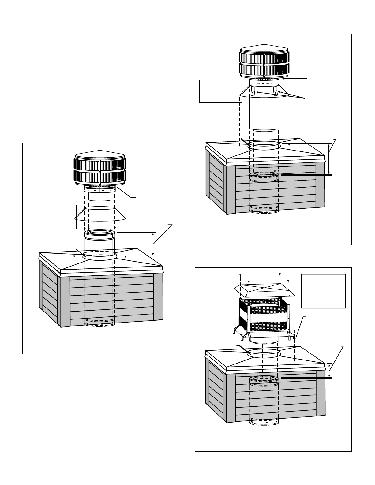
D. Install Termination Cap
Install the chimney sections up through the chase enclosure.
• Refer to termination cap instructions.
WARNING! Risk of Fire! The minimum overlap of cap
to pipe (as shown in the following illustrations) MUST
be met or chimney may separate from cap. Separation
allows sparks, heat and embers to escape.
NOTICE: Paint the termination cap with a rust-resistant
paint to protect against the effects of corrosion on those
parts exposed to the weather.
• TR344 Round Termination Cap
Termination
Cap
Slip
storm collar
around chimney pipe
before termination
cap pipe is snapped
into the chimney
pipe.
Caulk gaps between
storm collar & pipe,
and storm collar
& chase top.
Collar
2 in. (51 mm)
Minimum Height
Storm
Collar
Chimney
Pipe
Do NOT
block air holes
6 in. (153 mm)
Minimum top of
chase to top of
chimney pipe
• TR342 Round Telescoping Termination Cap
Assemble
storm collar
around extended
termination cap
pipe
once cap is
installed.
Caulk gaps between
storm collar & pipe,
and storm collar
& chase top.
Collar
2 in. (51 mm)
Minimum Height
Chase Top
Termination cap pipe and chimney section must overlap 1-1/2 in. (38 mm)
Figure 9.5 Installing a TR342 Round Telescoping Termination
Cap
Termination
Cap
Storm
Collar
Chimney
Pipe
Do NOT
block air
holes
3 clip brackets.
Slip over chase collar
and attach with screws
provided.
14 1/2 in. (368 mm)
Maximum
Chase
Chase Top
Chase
Termination cap pipe and chimney section must be snapped
together to maintain an overlap of 1-1/2 in. (38 mm).
Figure 9.4 Installing a TR344 Round Termination Cap
• ST375 Square Termination Cap
Place waterproof
caulk or sealer under
each flange of the
termination cap and
on top of each screw
to help prevent leaks.
Termination Cap
Collar
2 in. (51 mm)
Minimum Height
Chase Top
Chimney
Pipe
Termination cap pipe and chimney section must overlap 1-1/2 in. (38 mm)
Flange
4 3/4 in. (121 mm)
Maximum
top of chase to
top of
chimney section
Chase
34
Figure 9.6 Installing an ST375 Square Termination Cap
Heat & Glo • RH-36/RH-42 • 4044-153 • Rev W • 11/08
Page 35
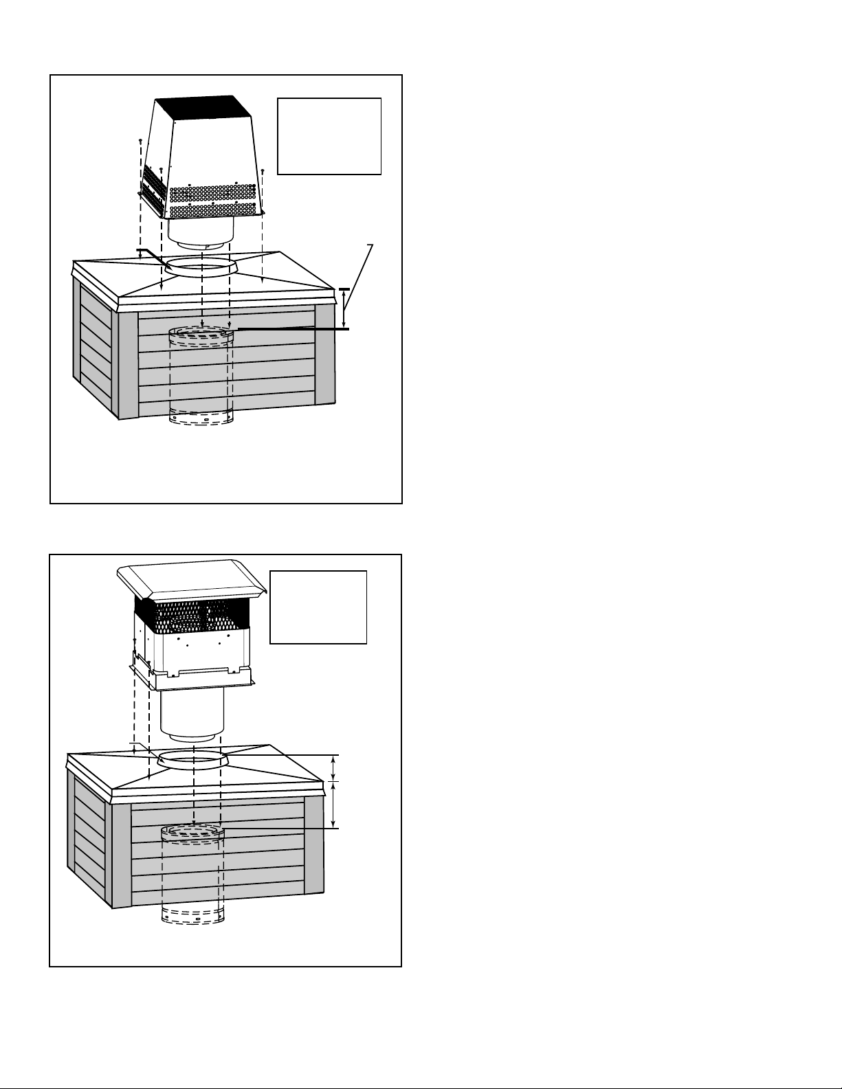
• TS345/TS345P Square Termination Cap
Place waterproof
sealer under each
flange of the termination cap and on top of
Termination Cap
Collar
2 in. (51 mm)
Minimum Height
Chase Top
Chimney
Pipe
Termination cap pipe and chimney section must overlap 1-1/2 in. (38 mm).
each screw to help
prevent leaks.
3 in. (76 mm)
Maximum
top of chase to
top of
chimney section
Chase
Figure 9.7 Installing a TS345/TS345P Square Termination Cap
• TCT375 Terra Cotta Cap
Place waterproof
sealer under each
flange of the termination cap and on top of
each screw to help
prevent leaks.
Termination Cap
The last section of pipe
must stop between 2 in.
(51 mm) above top of
Collar
2 in. (51 mm)
Minimum Height
Chase Top
Chimney
Pipe
chase and 7 in. (178
mm) below top of chase
2 in. (51 mm)
7 in. (178 mm)
Chase
Termination cap pipe and chimney section must overlap 1-1/2 in. (38 mm)
Figure 9.8 Installing a TCT375 Terra Cotta Cap
Heat & Glo • RH-36/RH-42 • 4044-153 • Rev W • 11/08
35
Page 36
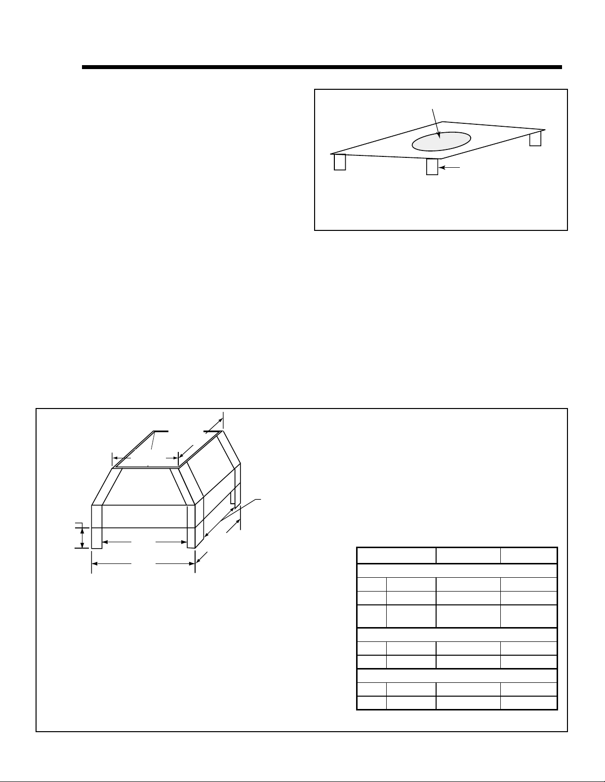
10
10
Shrouds
A. Radiation Shield
• Some shrouds require a radiation shield. Use where
specifi ed.
• Radiation shield must be constructed of minimum 26 ga
sheet metal.
B. Field Constructed Shrouds
WARNING! Risk of Fire! Shrouds must be constructed
as specifi ed. Improper construction may overheat chase
top.
• Chase top shrouds may be fi eld constructed where
permitted by regional building codes.
NOTICE: Some regional codes require an agency-Listed
shroud. Consult your local building offi cials.
• Hearth & Home Technologies Inc. supplies UL listed
shrouds. See your dealer for details.
• The following fi eld constructed shroud designs have
been tested for Hearth Technologies fi replace systems
and termination caps.
• The shrouds must be constructed from a minimum .018
in. (26 ga) thick aluminized steel.
Ø 17 1/2 in. (444.5 mm) Round Hole to fit over cap
3 in. (76 mm) tall legs
Length x Width to fit inside shroud
Figure 10.1 Radiation Shield
• The wire mesh is optional but recommended and must
be .018 in. thick minimum, 1/2 in. mesh.
Open Top Shroud (TR342 caps require radiation shield)
Min.
Top Dim.
Min.
Top Dim.
Min. Opening
Width
3 in (76 mm)
minimum
Min. Opening
Width
Min.
Base Dim.
Min.
Base Dim.
TS345 TR342 TR342/344TV
Min. Base Dims.
in 23 x 23 28 x 28 26 x 26
mm 584 x 584 711 x 711 660 x 660
Radiation Shield
Required
Min. Top Dims.
in 20 x 20 25 x 25 23 x 23
mm 508 x 508 635 x 635 584 x 584
Min. Opening Width
in 17 x 17 22 x 22 20 x 20
mm 432 x 432 559 x 559 508 x 508
Figure 10.2 Open Top Shroud Dimensions
36
Heat & Glo • RH-36/RH-42 • 4044-153 • Rev W • 11/08
Page 37
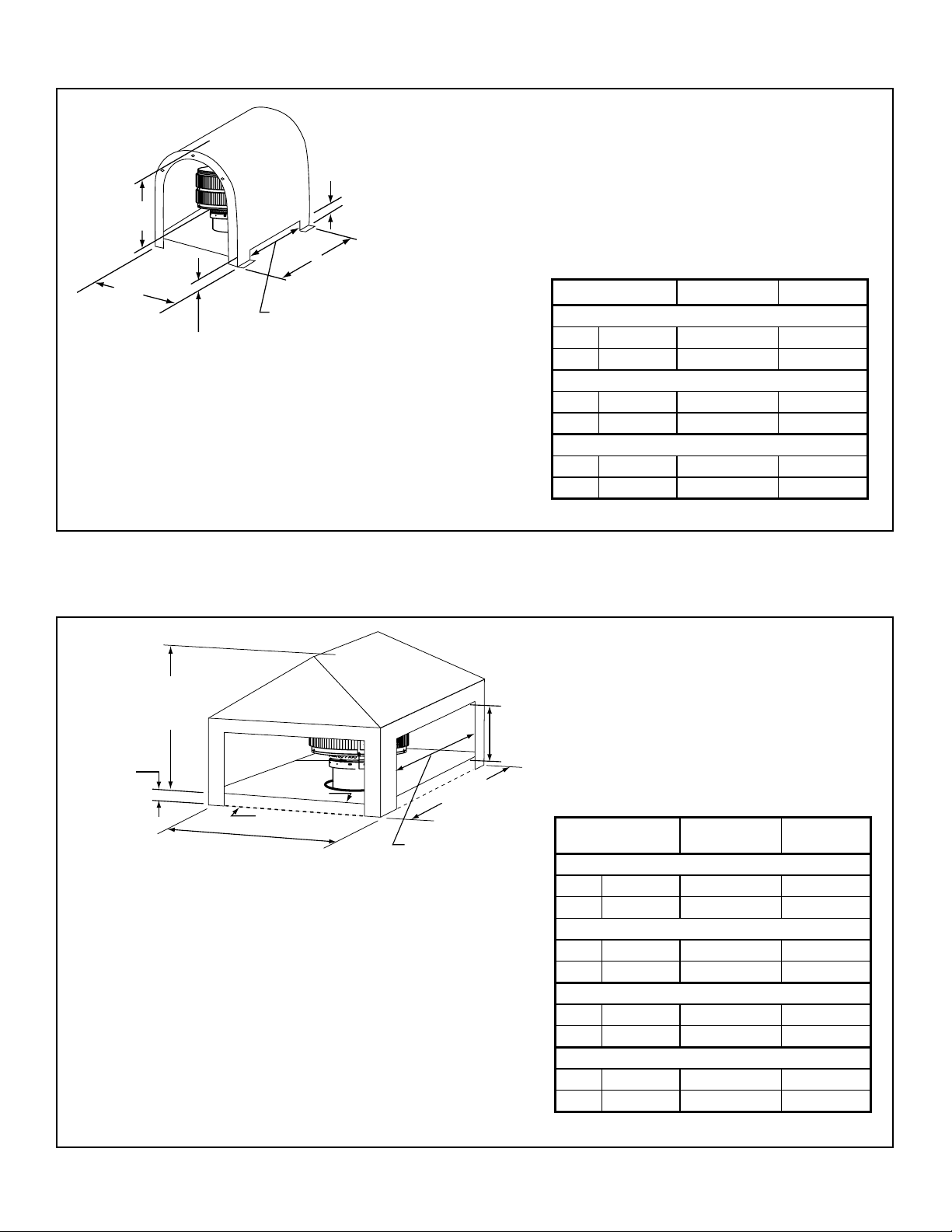
Mailbox Style Shroud (radiation shield required)
3 in. (76 mm)
Min. Opening Height
Min. Height
above radiation
shield
Min. Base Dim
Min.
Base Dim
Min. Opening Width
3 in. (76 mm) Min.
Radiation Shield Height
from top of Chase
Figure 10.3 Mailbox Style Shroud Dimensions
Roofed Style Shroud (radiation shield required)
Minimum
Height above
Radiation Shield
Termination
3 in. (76 mm)
Radiation
Shield Height
Min
. Base Dimension
Cap
Radiation Shield
Chase Top
Min. Opening Width
Minimum
Opening
Height
Minimum
Base Dimension
TS345 TR342 TR342/344TV
Min. Base Dims.
in N/A 26-1/2 x 28 28 x 30
mm N/A 673 x 711 711 x 762
Min. Height Above Radiation Shield
in N/A 21-1/4 20-1/2
mm N/A 540 521
Min. Opening Width
in N/A 20-1/2 x 22 22 x 24
mm N/A 521 x 559 559 x 610
TS345/445
in N/A 27 x 27 27 x 27
mm N/A 686 x 686 686 x 686
Min. Height Above Radiation Shield
in N/A 16 16
mm N/A 406 406
in N/A 21 21
mm N/A 533 533
Min. Opening Height
in N/A 12 12
mm N/A 305 305
TR342/344
TR442/444 TR342/344TV
Min. Base Dims.
Min. Opening Width
Figure 10.4 Roofed Style Shroud Dimensions
Heat & Glo • RH-36/RH-42 • 4044-153 • Rev W • 11/08
37
Page 38
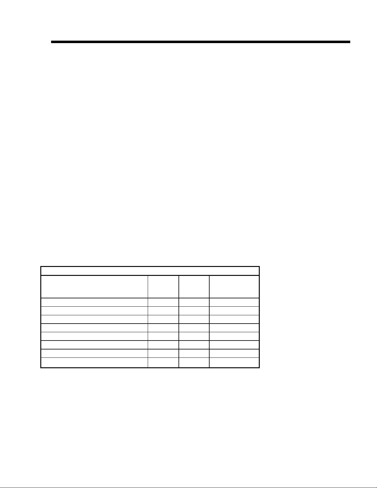
11
11
Finishing
A. Non-Combustible Materials
• Materials which will not ignite and burn, composed of
any combination of the following:
- Steel - Iron
- Brick - Tile
- Concrete - Slate
- Glass - Plasters
• Materials reported as passing ASTM E 136, Standard
Test Method for Behavior of Metals, in a Vertical Tube
Furnace at 750° C
B. Combustible Materials
• Materials made of or surfaced with any of the following
materials:
- Wood - Compressed paper
- Plant fi bers - Plastic
• Any material that can ignite and burn; fl ame proofed or
not, plastered or un-plastered
Table 11.1
R = 1/k x inches of thickness
C. Hearth Extension
WARNING! Risk of fi re! High temperatures, sparks,
embers or other burning material falling from the fi replace
may ignite fl ooring or concealed combustible surfaces.
• Protective metal hearth strips MUST be installed.
• Hearth extensions MUST be installed exactly as
specifi ed.
• You MUST use a hearth extension with this fi replace.
• Refer to Figure 11.1 for minimum dimensions.
• This fi replace has been tested and approved for use with
a hearth extension insulated to a minimum R value of
1.03.
• The hearth extension material MUST be covered with
tile, stone or other non-combustible material.
• Manufactured hearth materials will usually have a
published R value (resistance to heat) or k value
(conductivity of heat). Refer to the formula in Table 11.1
to convert a k value to an R value,
• Refer to Table 11.2 for hearth extension insulation
alternatives.
Table 11.2
Hearth Extension Insulation Alternatives-Total minimum R Value must equal 1.03
Material
Hearth & Home HX3, HX4 (Micore 300™) 0.49 2.06 1/2 in.
USG Micore 160™ 0.39 2.54 1/2 in.
USG Durock™ Cement Board 1.92 0.52 2 in.
Cement Mortor 5.0 0.20 5-1/8 in.
Common Brick 5.0 0.20 5-1/8 in.
Ceramic Tile 12.50 0.08 12-1/4 in.
Armstrong™ Privacy Guard Plus 0.46 2.18 1/2 in.
Marble 14.3-20.0 0.07-0.05 14-5/8 in. - 20-3/8 in.
k per inch
thick
r per inch
thick
Minimum
thickness
required
38
Heat & Glo • RH-36/RH-42 • 4044-153 • Rev W • 11/08
Page 39

4 in. (102 mm)
minimum between
bottom of fireplace opening
and finished surface of hearth extension
C
A
Raised Hearth Extension Framing
WARNING! Risk of Fire. A raised hearth extension built
fl ush with the fi replace opening (Figure 11.3) or less than
4 in. (102 mm) below the fi replace opening requires the
fi replace be installed on a non-combustible surface.
The hearth framing must be constructed of non-combustible materials (Figure 11.2) and placed on 1/2 in. Micore,
or equivalent material (Figure 11.4). When creating the
platform, allow for the thickness of the non-combustible
fi nishing materials (Figure 11.5).
IMPORTANT! Hearth extension design must be
determined before installation of fi replace.
Noncombustible
Material
B
Figure 11.1 Hearth Extension Dimensions
Continuous, noncombustible sealant
1/2 in. Micore Hearth
Extension (or
equivalent insulation)
See Table 11.2.
Floor constructed of wood or
other combustible material
Figure 11.2 Hearth Extension Construction
Tile, stone or other
non-combustible material
2 in. (51 mm) of the Protective
Metal Hearth Strip is required
under the front of the fireplace
C
D
Fireplace
Opening
(102 mm) min.
4 in.
Noncombustible
Finishing Material
Noncombustible
Framing Material
1/2 in. Micore
or equivalent
insulation
Figure 11.3 Raised Platform Hearth Extension Detail
Protective Metal
Hearth Strips
Floor
Noncombustible
Framing Material
Figure 11.4 Raised Platform Hearth Extension-Framing Materials
Heat & Glo • RH-36/RH-42 • 4044-153 • Rev W • 11/08
1/2 in. Micore or
equivalent insulation
39
Page 40
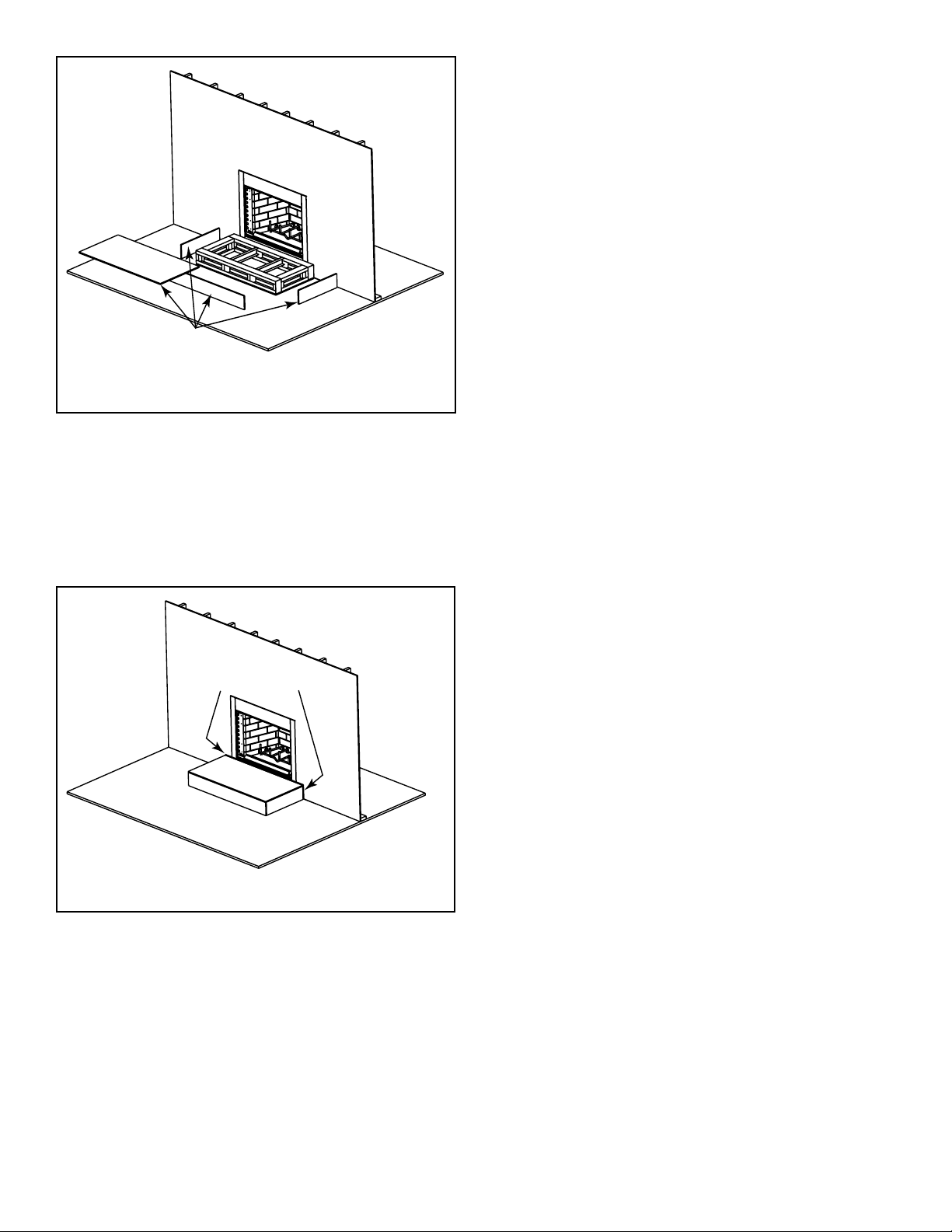
Noncombustible
Finishing Materials
Figure 11.5 Raised Platform Hearth Extension-Finishing Materials
Non-combustible Sealant
After completing the framing and applying the facing
materials over the framing, a bead of non-combustible
sealant must be used to close off any gaps at the top and
sides between the fi replace hearth.
Non-combustible Sealant
Figure 11.6 Place Non-combustible Sealant
40
Heat & Glo • RH-36/RH-42 • 4044-153 • Rev W • 11/08
Page 41
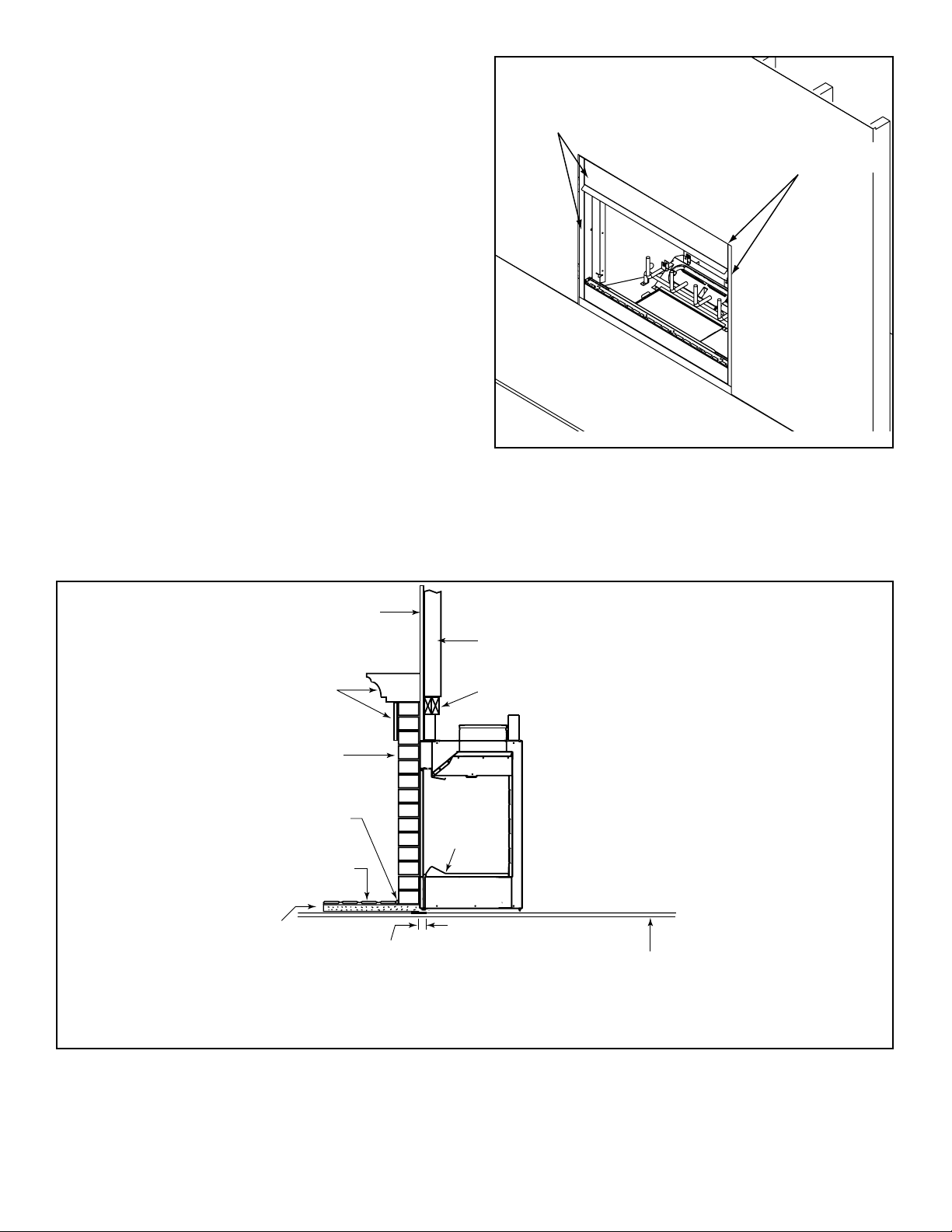
D. Finishing Material
Refer to Sections 11.A. and Sections 11.B. for combustible/noncombustible materials. Refer to Figure 11.7 for
noncombustible zone.
WARNING! Risk of Fire!
• Use only non-combustible framing material below
standoffs.
• Sheetrock, wood or other combustibles must NOT be
used as sheathing or facing in the noncombustible
zone.
• DO NOT cover metal fi replace front with combustible
materials.
• Install combustible materials only to specifi ed clearances
on top front and side edges.
• Complete framing and apply facing material (drywall)
over framing.
• A bead of 300-deg F minimum non-combustible sealant
must be used to close off any gaps at the top and sides
between the fi replace and facing to prevent cold air
leaks.
• Large gaps can be bridged with fiberglass rope
gasket.
• Only non-combustible materials may be used to cover
the metal fi replace front.
You must maintain clearances.
These surfaces
may be covered
with non-combustible
material.
Figure 11.7 Noncombustible Facing
Non-combustible
sealant.
Finished combustible wall
Combustible material
Non-combustible
decorative facing
(up to full brick depth)
Continuous,
non-combustible sealant
Tile, stone or other
non-combustible material
1/2 in. Micore
or equivilent
insulation
Figure 11.8 Decorative Facing
Flat 2 x 4 stud wall
2 x 4 header, flush with
front of stand-offs
Hearth
Refractory
Metal strips are placed 2 in. (51 mm)
under the front of the fireplace and must
extend beyond the front and sides of
fireplace opening by 2 in. (51 mm)
Floor constructed of wood or
other combustible material
Heat & Glo • RH-36/RH-42 • 4044-153 • Rev W • 11/08
41
Page 42

E. Combustible Mantel
• See Figure 11.9.
• A combustible mantel may be positioned no lower than 12
in. (305 mm) above the top of the fi replace opening.
• A combustible mantel may have a maximum depth of
12 in. (305 mm).
• Combustible trim and materials cannot be placed within
6 in. (152 mm) of the fi replace opening (top or sides).
• Combustible materials projecting more than 1-1/2 in.
(38 mm) shall not be placed within 12 in. (305 mm) from
the top of the fi replace opening.
• Combustible trim must not cover the metal surfaces of
the fi replace.
• Mantel clearance is in accordance with Section 7-3.3.3
of ANSI/NFPA211.
7 ft (2134 mm)
minimum
base of fireplace
to ceiling
Combustible Wall
2 x 4 stud wall
Standoffs
Combustible
Decorative Facing
12 in./305 mm MAXIMUM
Noncombustible
Decorative Facing
12 in./305 mm MINIMUM
Seal joint with
non-combustible
sealant
Measured from top of fireplace opening
Figure 11.9 Clearances to Mantels or other Combustibles above Fireplace
Î
42
Heat & Glo • RH-36/RH-42 • 4044-153 • Rev W • 11/08
Page 43

F. Sidewalls/Surrounds
• Adjacent combustible sidewalls must be located
a minimum of 12 in. (305 mm) from the fireplace
opening.
• Combustible or non-combustible mantel legs, surrounds
and stub walls may be constructed per Figure 11.10.
9 3/4 in.
4 in.
[248 mm]
[102 mm]
BRICK
FRONT
39° angle
12 in.
[305 mm]
B
FLUSH
FRONT
A
B
50° angle
12 in.
[305 mm]
mensions
Outside Di-
A
Opening
Fireplace
in. 36 41
Model #
mm 914 1041
RH-36
in. 42 47
RH-42
mm 1067 1194
11 1/4 in.
[286 mm]
Figure 11.10 Mantel Leg or Wall Projections (acceptable on both sides of opening)
Heat & Glo • RH-36/RH-42 • 4044-153 • Rev W • 11/08
43
Page 44

12
12
Accessories
A. Gas Log/Lighter Provision
WARNING! Fire and/or Asphyxiation Risk! Use with
solid wood fuel or decorative gas appliance only. Gas fi re
generates fumes.
• DO NOT install unvented gas logs
• Damper must be locked fully open when gas logs are
installed
A certifi ed gas log lighter or decorative gas log set can be
installed in this fi replace.
• Maximum input is 100,000 BTU/hr.
• Decorative gas appliance must be certifi ed to ANSI
Z21.60 “Standard for Decorative Gas Appliances for
Installation in Vented Fireplaces”.
• Must be installed in accordance with the National Fuel
Gas Code, ANSI Z223.1.
• A gas log set must incorporate a gas shutoff.
• Gas Log set requires the damper to be locked fully
open.
• A listed automatic damper system with safety interlock
may be used in this fi replace with only compatible,
listed gas log sets. See damper system manufacturer’s
insturctions.
• Knockouts are provided on both sides of the fi replace
and in refractories for 1/2 in. (13 mm) iron pipe.
• Seal refractory around pipe with fi replace mortar or a
non-combustible sealant.
B. Wood Burning Inserts
WARNING! Risk of Fire! Improper installation of wood inserts may cause fi replace or chimney system to overheat.
If a wood burning insert is being installed in this fi replace,
Hearth & Home Technologies recommends full reline of
the chimney.
• Cooling air openings at the top of the chimney must not
be obstructed in any manner.
• Hearth & Home Technologies recommends securing the
reline at the top of the fl ue and using the cap certifi ed for
use with this fi replace system.
Outer Shell
Firebox
Refractory
Seal with
fireplace mortar
or non-combustible sealant
Gas Line
Repack
Insulation
Knockout
Figure 12.1 Gas Line Installation
of Fireplace
Gas Line
4 in.
(102 mm)
Maintain air clearance
to combustibles.
Combustible
Materials
1 1/2 in. (38 mm)
air space around
pipe
Combustible materials
may be located at zero
clearance to gas line
beyond 4 in. (102 mm)
from fireplace side.
44
Heat & Glo • RH-36/RH-42 • 4044-153 • Rev W • 11/08
Page 45

13
13
Reference Materials
A. Fireplace Dimensions
39-1/2 in.
(1003 mm)
21 in.
(533 mm)
Gas
Knockout
9-1/4 in.
(235 mm)
7-1/2 in.
(191 mm)
7-1/2 in.
(191 mm)
7-3/8 in.
(187 mm)
D
C
21-3/8 in.
(543 mm)
7-1/2 in.
(191 mm)
B
18-3/4 in.
(476 mm)
21 in.
(533 mm)
9-1/4 in.
14-1/8 in.
A
(235 mm)
(359 mm)
in. 36 41 23-3/4 11-7/8
in. 42 47 29-3/4 14-7/8
mm 914 1041 603 302
mm 1067 1194 756 378
Model # A B C D
RH-36
RH-42
7-1/2 in.
Air
Outside
Gas
Knockout
Heat & Glo • RH-36/RH-42 • 4044-153 • Rev W • 11/08
(191 mm)
45
Page 46

B. Optional Components
52 in.
(1321 mm)
1/2 in.
(13 mm)
HX3 Hearth Extension
66 in.
(1676 mm)
16 in.
(406 mm)
Bifold Glass Doors
DM1036, DM1042
20 in.
(508 mm)
4044-036 Air Kit Parts
1/2 in.
(13 mm)
HX4 Hearth Extension
ID4 Insulated Duct
42 in.
(1067 mm)
UD4 Uninsulated Duct
42 in.
(1067 mm)
4 in. (102 mm) i.d.
4 in. (102 mm) i.d.
Outside Air
Hood
Fastener Pack
2 Wire Ties
AK24
Outside Air Kit
Outside Air
Plate
Assembly
46
See your Heat & Glo dealer for a complete listing of optional components.
Heat & Glo • RH-36/RH-42 • 4044-153 • Rev W • 11/08
Page 47

C. Chimney Components
i
i
The following pictures show only those chimney components which may be safely used with this fi replace.
CAK4A Chimney Air Kit
ID4 Insulated Duct/Outside Air
UD4 Uninsulated Duct/Outside Air
SL306 Chimney Section - 6 in. (152 mm) long
SL312 Chimney Section - 12 in. (305 mm) long
SL318 Chimney Section - 18 in. (457 mm) long
SL324 Chimney Section - 24 in. (610 mm) long
SL336 Chimney Section - 36 in. (914 mm) long
SL348 Chimney Section - 48 in. (1219 mm) long
SL3 Chimney Stabilizer
SL315 Chimney Offset/Return - 15 deg
SL330 Chimney Offset/Return - 30 deg
FS338 Ceiling Firestop - Straight
FS339 Ceiling Firestop - 15 deg
FS340 Ceiling Firestop - 30 deg
AS8 SL300 Straight Attic Insulation Shield, 24 in. (610 mm)
JB877 Chimney Joint Band
CB876 Chimney Bracket
RF370 Roof Flashing - Flat to 6/12 Pitch
RF371 Roof Flashing - 6/12 to 12/12 Pitch
TR344 Round Termination Cap
TR342 Round Telescoping Termination Cap
ST375 Square Termination Cap
TS345 Square Termination Cap
TS345P Square Termination Cap - Painted
TCT375 Terra Cotta Termination Cap
CT35 Chase Top
LDS33 Decorative Shroud - 3 ft x 3 ft (.91 m x .91 m)
LDS46 Decorative Shroud - 4 ft x 6 ft (1.22 m x 1.83 m)
LDS-BV Decorative Shroud - 26 in. x 26 in. (660 mm x 660 mm)
Field Constructed Shrouds (See “Woodburning
Termination Cap”)
CT-3A Adapter - May be used with the following copper caps
CT-King
CT-Queen
CT-Bishop-I
CT-Bishop-II
CT-Knight-I
CT-Pawn
12 in.
(305 mm)
5-1/4 in.
(133 mm)
12 in.
(305 mm)
4 in. (102 mm)
10-1/2 in.
(287 mm)
8 in.
(203 mm)
Catalog #
A = Actual Length
B = Effective Length (length of
ID4 Insulated Duct
4 in. (102 mm)
42 in.
(1067 mm)
UD4 Uninsulated Duct
4 in. (102 mm)
42 in.
A
B
Chimney Sections
AB
in mm in mm
SL306 6 152 4-3/4 121
SL312 12 305 10-3/4 273
SL318 18 457 16-3/4 425
SL324 24 610 22-3/4 578
SL336 36 914 34-3/4 883
SL348 48 1219 46-3/4 1187
chimney part after it has
been snapped to another)
Diameter
20-3/4 in.
(527 mm)
4-3/4 in. (121 mm)
Effective Height
(203 mm)
Diameter
10-1/2 in.
(267 mm)
10-1/2 in.
(267 mm)
Inside
8 in.
Outside
CAK4A Chimney Air Kit
Heat & Glo • RH-36/RH-42 • 4044-153 • Rev W • 11/08
SL3 Vent Stabilizer
47
Page 48
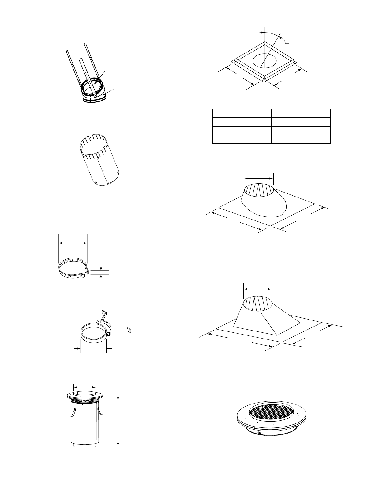
Effective
Height
4-3/4 in.
(121 mm)
SL315/SL330 Offset/Return
Assembled
Diameter: 14 1/2 in./368 mm
Height: 24 in./610 mm
Inside
Diameter
8 in. (203 mm)
Outside
Diameter
10-1/2 in.
(267 mm)
A
B
14-1/2 in.
(368 mm)
Ceiling Firestop
Catalog # A B
FS338 0-deg. 14-1/2 in. 368 mm
FS339 15-deg. 18-3/8 in. 467 mm
FS340 30-deg. 23 in. 584 mm
12 in.
(305 mm)
AS8 Straight Attic Insulation Shield
10-1/2 in.
(267 mm)
2 in. (51 mm)
JB877 Chimney Joint Band
10-1/2 in.
(267 mm)
CB876 Chimney Joint Band
7 3/4 in.
27-3/8 in.
(695 mm)
31 in.
(787 mm)
24-5/8 in.
(625 mm)
RF370 Roof Flashing
12 in.
(305 mm)
24-5/8 in.
(625 mm)
RF371 Roof Flashing
48
CT-3A
26 in.
TR-TVK
TR Top Vent Kit
Heat & Glo • RH-36/RH-42 • 4044-153 • Rev W • 11/08
Page 49
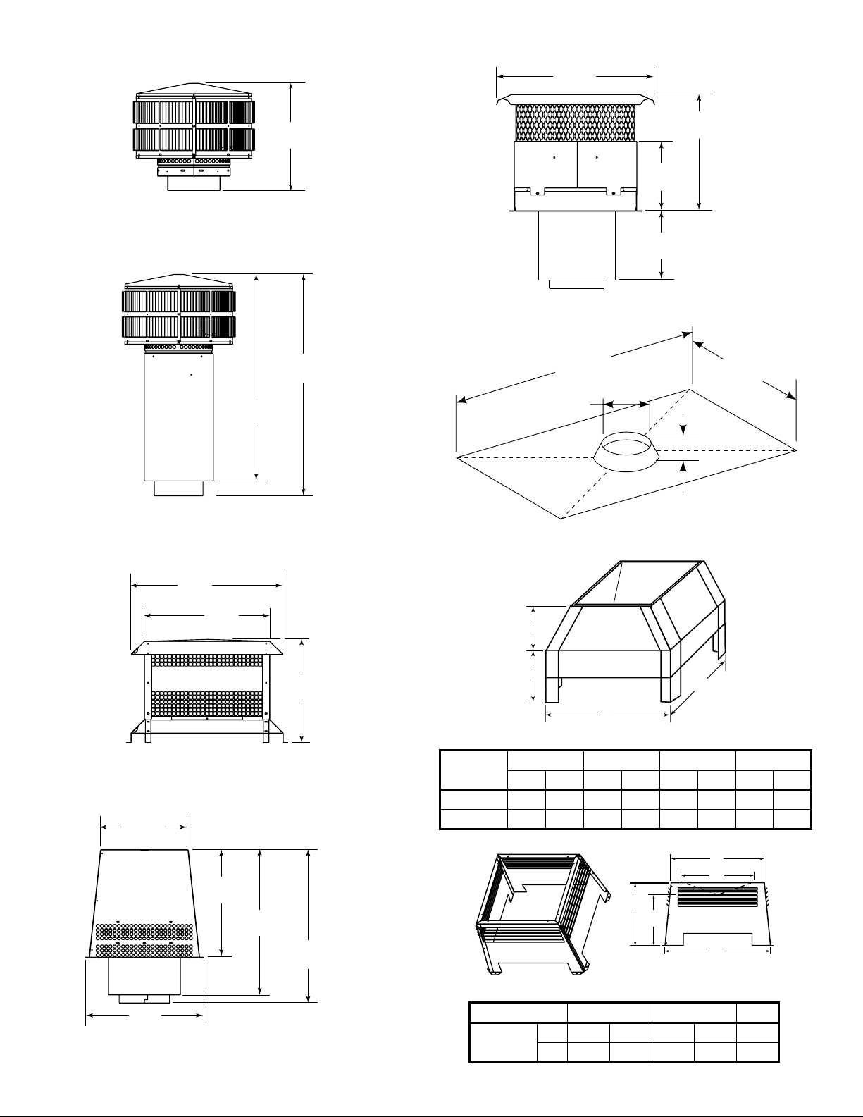
20 in.
(508 mm)
15-3/4 in.
(400 mm)
TR344 Round Termination Cap
34-3/4 in.
(883 mm)
32-1/2 in.
(826 mm)
TR342 Round Telescoping Termination Cap
TCT375 Terra Cotta Cap
72 in.
(1829 mm)
10-7/8 in.
(276 mm)
CT35 Chase Top
17 in.
(432 mm)
9-3/8 in.
(238 mm)
9-1/4 in.
(235 mm)
36 in.
(914 mm)
2 in. (51 mm)
23 in.
(584 mm)
19 in.
(483 mm)
15-5/8 in.
(397 mm)
ST375 Square Termination Cap
13-1/4 in.
(337 mm)
16-1/4 in.
(413 mm)
22 in.
(559 mm)
23-1/8 in.
(587 mm)
18 in.
(457 mm)
TS345/TS345P Square Termination Cap
C
D
A
LDS33/LDS46 Decorative Shroud
B
ABCD
Catalog #
LDS33 36 914 36 914 8-1/2 216 11 279
LDS46 48 1219 72 1829 8-1/2 216 11 279
in. mm in. mm in. mm in. mm
E
D
C
B
A
LDS-BV Decorative Shroud
Catalog # A B C D E
LDS-BV
in. 26 12-1/2 15-1/2 22 23
mm 660 318 394 533 584
Heat & Glo • RH-36/RH-42 • 4044-153 • Rev W • 11/08
49
Page 50
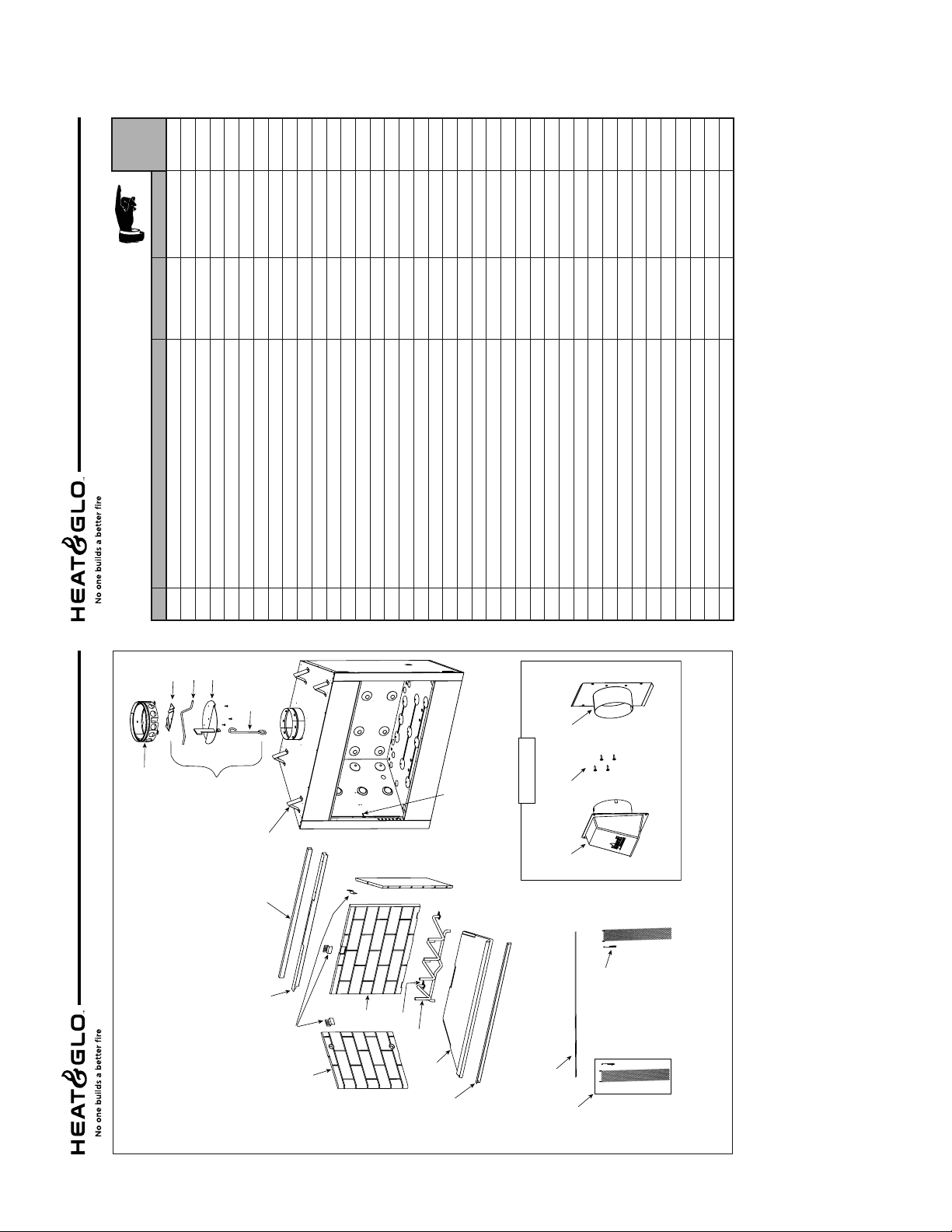
D. Service Parts
RH-36
Service Parts
Stocked
at Depot
Ending Manufacturing Date: Active
Beginning Manufacturing Date: Jan. 2005
Service Parts Diagram
Royal Hearth Woodburning Fireplace
N
4044-111
Qty. 4 req
N
N
4044-131
11847
1 ea.
Qty. 3 req
N
4044-114
Qty. 2 req
N
4044-170
Qty. 2 req
Y
N
4044-028
4044-175
1 ea.
Qty. 2 req
N
10002
1 ea.
N
N
N
N
N
31527
SRV4044-038
12010B
2 ea.
Qty. 2 req
Qty. 2 req
Fastener Pack
Smoke Shield Kit Installation Instructions 4044-165
Extended Smoke Shield Kit
Door Pivot Clip
Y
N
N
101025
4044-161
4044-116
Qty. 2 req
Qty. 4 req
Qty. 2 req
Hair Pin Clip
Nailing Flange
Smoke Baffl e
N
18320
Qty. 2 req
Strip Protector
Installation Instructions and Owner's Manual 4044-153 N
06/08
1 Starter Section Assembly 22069BY2 Damper Kit 4044-029Y3 Damper Weight 19785AN4 Damper Rod 28900N5 Damper Blade Assembly 4044-030N6 Damper Control 4044-152N7 Top Standoff
ITEM DESCRIPTION COMMENTS PART NUMBER
IMPORTANT: THIS IS DATED INFORMATION. When requesting service or replacement
parts for your appliance please provide model number and serial number. All parts listed
in this manual may be ordered from an authorized dealer.
3
4
RH-36
1
Ending Manufacturing Date: Active
Beginning Manufacturing Date: Jan. 2005
Service Parts Diagram
Royal Hearth Woodburning Fireplace
Service Parts
8 Door Track (used for upper) 15425N9 Smoke Shield
11 Side Refractory
12 Back Refractory 4044-130N13 Grate Retainer
10 Refractory Retainer
14 Grate GR41Y15 Hearth Refractory 4044-129N16 Hearth Retainer 4044-128N17 Firescreen Assembly
5
18 Firescreen Rod
19 Firescreen Handle
20 Outside Air Replacement Kit 4044-036Y21 Outside Air Shield 33271Y22 Fastener Pack 12010BN23 Outside Air Plate Assembly 4044-031
06/08
6
23
2
Air Handle
20 - Air Kit
22
)
(Duct sold separately
7
21
8
19
9
12
10
13
14
50
11
15
16
17
18
Heat & Glo • RH-36/RH-42 • 4044-153 • Rev W • 11/08
Part number list on following page.
Page 51

D. Service Parts (continued)
RH-42
Service Parts
Stocked
at Depot
Ending Manufacturing Date: Active
Beginning Manufacturing Date: Jan. 2005
Service Parts Diagram
Royal Hearth Woodburning Fireplace
N
4044-111
Qty. 4 req
N
N
4044-120
11847
1 ea.
Qty. 3 req
N
4044-114
Qty. 2 req
N
4044-170
Qty. 2 req
Y
N
4044-027
4044-172
1 ea.
Qty. 2 req
N
10002
1 ea.
N
N
N
N
N
31527
SRV4044-037
12010B
2 ea.
Qty. 2 req
Qty. 2 req
Fastener Pack
Smoke Shield Kit Installation Instructions 4044-165
Extended Smoke Shield Kit
Door Pivot Clip
Y
N
N
101025
4044-161
4044-116
Qty. 2 req
Qty. 4 req
Qty. 2 req
Hair Pin Clip
Nailing Flange
Smoke Baffl e
N
18320
Qty. 2 req
Strip Protector
Installation Instructions and Owner's Manual 4044-153 N
06/08
1 Starter Section Assembly 22069BY2 Damper Kit 4044-029Y3 Damper Weight 19785AN4 Damper Rod 28900N5 Damper Blade Assembly 4044-030N6 Damper Control 4044-152N7 Top Standoff
ITEM DESCRIPTION COMMENTS PART NUMBER
IMPORTANT: THIS IS DATED INFORMATION. When requesting service or replacement
parts for your appliance please provide model number and serial number. All parts listed
in this manual may be ordered from an authorized dealer.
3
RH-42
Ending Manufacturing Date: Active
Beginning Manufacturing Date: Jan. 2005
Service Parts Diagram
Royal Hearth Woodburning Fireplace
Service Parts
1
4
8 Door Track (used for upper) 15427N9 Smoke Shield
11 Side Refractory
12 Back Refractory 4044-113N13 Grate Retainer
10 Refractory Retainer
14 Grate GR40Y15 Hearth Refractory 4044-112N16 Hearth Retainer 4044-109N17 Firescreen Assembly
18 Firescreen Rod
19 Firescreen Handle
20 Outside Air Replacement Kit 4044-036Y21 Outside Air Shield 33271Y22 Fastener Pack 12010BN23 Outside Air Plate Assembly 4044-031
06/08
5
6
23
2
Air Handle
20 - Air Kit
22
)
(Duct sold separately
7
21
8
9
12
10
11
13
14
17 - Screen Assembly
19
18
15
16
Part number list on following page.
Heat & Glo • RH-36/RH-42 • 4044-153 • Rev W • 11/08
51
Page 52
E. Contact Information
Please contact your Heat & Glo dealer with any questions or concerns.
For the number of your nearest Heat & Glo dealer, please visit www.heatnglo.com.
– NOTES –
CAUTION
DO NOT
DISCARD
DO NOT DISCARD THIS MANUAL
• Important operating
and maintenance
instructions included.
This product may be covered by one or more of the following patents: (United States) 4593510, 4686807, 4766876,
4793322, 4811534, 5000162, 5016609, 5076254, 5113843, 5191877, 5218953, 5263471, 5328356, 5341794, 5347983,
5429495, 5452708, 5542407, 5601073, 5613487, 5647340, 5688568, 5762062, 5775408, 5890485, 5931661, 5941237,
5947112, 5996575, 6006743, 6019099, 6048195, 6053165, 6145502, 6170481, 6237588, 6296474, 6374822, 6413079,
6439226, 6484712, 6543698, 6550687, 6601579, 6672860, 6688302B2, 6715724B2, 6729551, 6736133, 6748940,
6748942, 6769426, 6774802, 6796302, 6840261, 6848441, 6863064, 6866205, 6869278, 6875012, 6880275, 6908039,
6919884, D320652, D445174, D462436; (Canada) 1297749, 2195264, 2225408, 2313972; (Australia) 780250, 780403,
1418504 or other U.S. and foreign patents pending.
52
Heat & Glo • RH-36/RH-42 • 4044-153 • Rev W • 11/08
• Read, understand
and follow these
instructions for safe
installation and
operation.
• Leave this manual with
party responsible for
use and operation.
 Loading...