

Page 1
RCT-MLT-II Remote Control Kits
- Installation and Operating Instructions -
INTRODUCTION
The remote control system can be operated thermostatically or manually from the transmitter. The system operates on radio frequencies (RF) within a 20 foot range. Can
be used with DSI, IPI or Standing Pilot systems.
This remote control kit has a hand held transmitter that
can be used as a remote on/off or as a thermostat. The
transmitter display shows the current room temperature,
target temperature, timer setting, on/off status, low battery indicator, current time, burner/valve operation and
fan operation. Electrical ratings for the receiver are: 1 10
VAC, 60 Hz, 6 W.
If pertinent, see additional fi replace wiring diagrams on
pages 9 to 11.
INSTALLATION PRECAUTIONS
This remote control kit is tested and safe when installed
in accordance with this installation manual.
Installation of this kit MUST be done by a qualifi ed
service technician.
NOTE: A manometer MUST be used to set the
manifold pressure on the gas valve.
It is the responsibility of the installer to read all instructions before starting installation and to follow these
instructions carefully during installation. Modifi cation of
the remote control system or any of its components will
void the warranty and may cause a fi re hazard.
NOTE: The factory installed junction box in the gas
fi replace must be wired with 110 VAC before installing this kit. See Installation Instructions section.
CAUTION: All wiring should be done by a qualifi ed
electrician and shall be in compliance with local codes
and with the National Electric Code ANSI/NFPA No. 70current (in the United States), or with the current CSA
C22.1 Canadian Electric Code (in Canada).
WARNING: DO NOT CONNECT 110-120 VAC
WIRING TO THE GAS CONTROL VAL VE OF THIS
APPLIANCE.
FCC REQUIREMENTS
WARNING: CHANGES OR MODIFICATIONS TO
THIS UNIT NOT EXPRESSLY APPROVED BY
THE PARTY RESPONSIBLE FOR COMPLIANCE
COULD VOID THE USER’S AUTHORITY T O OPERATE THE EQUIPMENT.
NOTE: This equipment has been tested and found
to comply with the limits for a Class B digital device,
pursuant to Part 15 of the FCC Rules. These limits are
designed to provide reasonable protection against harmful interference in a residential installation. This equipment generates, uses, and can radiate radio frequency
energy and, if not installed and used in accordance with
the instructions, may cause harmful interference to radio
communications. However, there is no guarantee that
interference will not occur in a particular installation. If
this equipment does cause harmful interference to radio
or television reception, which can be determined by turning the equipment off and on, the user is encouraged
to try to correct the interference by one or more of the
following measures:
- Reorient or relocate the receiving antenna.
- Increase the separation between the equipment and
receiver.
- Connect the equipment into an outlet on a circuit different from that to which the receiver is connected.
- Consult the dealer or an experienced radio TV technician for help.
Canadian Equipment Requirements
This digital apparatus does not exceed the (Class A/Class
B)* limits for radio noise emissions from digital apparatus set out in the Radio Interference Regulations of the
Canadian Department of Communications. Le present
appareil numerique n’emet pas de bruits radioelectriques
depassant les limites applicables aux appareils numeriques (de la class A/de la class B)* prescrites dans le
Reglement sur le brouillage radioelectrique edicte par le
ministere des Communications du Canada.
This device complies with RSS-210 of Industry and Science Canada. Operation is subject to the following two
conditions: (1) this device may not cause interference,
and (2) this device must accept any interference, including interference that may cause undesired operation of
the device.
Printed in U.S.A. Copyright 2008,
Hearth & Home Technologies Inc.
20802 Kensington Boulevard, Lakeville, MN 55044
100-907F 4/08
1
Page 2
INSTALLATION INSTRUCTIONS
Installing Electrical Service to the Junction Box
WARNING: TURN ELECTRICAL POWER OFF AT
THE CIRCUIT BREAKER BEFORE BEGINNING
THIS INSTALLATION.
Wire Colors
• Gas Valve - Millivolt or
Electronic Ignition ..............................................Red
• Fan/Blower - 110 VAC .........................Plug from Fan
• Flame Controller - HI/LO solenoid ..................Orange
NOTE: Some appliances do not have a cover plate.
Instead, there is a hole through which the Romex clamp
is attached to the outer wrap.
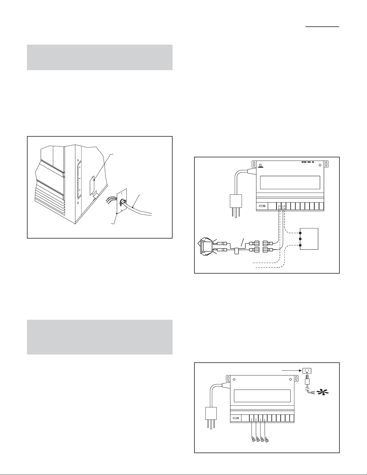
1. Remove the electrical cover plate from the lower side
of the fi replace. Remove the knock-out from the plate
and attach the Romex clamp (screws to the outside)
(see Figure 1).
ACCESS HOLE
110 VAC
SERVICE
COVER
PLATE
Figure 1
2. Feed the electrical service wires through the Romex
clamp and secure the wires to the clamp.
3. Using the wire nuts provided, connect the service
wires to the junction box. The black wires to the black
service wire, the white wires to the white service wire,
and the service ground wire to the ground stud of the
junction box.
4. Re-attach the cover plate to the outside of the fi re-
place.
RECEIVER WIRING INSTRUCTIONS
Incorrect wiring connections WILL cause damage to the
gas valve or electronic module operating the gas appliance and may also damage the remote receiver.
Wiring Flame Function (Standing Pilot, DSI, IPI)
Connect the remote receiver by connecting the two red
wires leading from the remote receiver to the red and
brown remote wires labeled “FOR USE WITH REMOTE
OR WALL SWITCH ONLY”. See Figure 2.
REMOTE
RECEIVER
RED
VALVE
TH
TP
TH
TP
ON/OFF
SWITCH REMOTE SWITCH
Figure 2.
BROWN
RED
PIGTAIL
WALL
SWITCH
RED
Alternative Wiring for units with a wall switch
Disconnect the wall switch wire from the TH terminal on
the valve and connect this wire to male connector supplied on the receiver. Connect remaining female connector from receiver to the TH terminal on the valve.
WARNING: LEAVE ELECTRICAL POWER OFF
AT THIS TIME. DO NOT RESTORE POWER UNTIL THE REMOTE CONTROL SYSTEM IS COMPLETELY INSTALLED.
REMOTE RECEIVER
Important: The remote receiver should be positioned
close to front in right or left corner where ambient
temperatures do not exceed 170º F.
The remote receiver is powered by 1 10-120V AC. It plugs
into a standard polarized duplex receptacle.
Locating Receiver and Operating Functions
This remote receiver can be positioned under the fi rebox
in the control compartment of the fi replace if ambient
temperatures do not exceed 170º F. This system is designed to control the following components:
Adding Optional Fan/Blower
Plug 2-prong fan cord directly into the 3 prong polarized
plug on the back of the receiver (see Figure 3). This
receptacle output is 110/120 VAC, 3 AMP.
(Receptacle on back)
Figure 3. Adding Fan/Blower
2
LEARN
REMOTE
RECEIVER
110/120 VAC, 3A
Line cord
from fan
Page 3
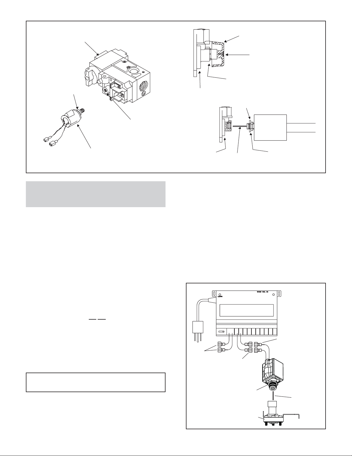
GAS CONTROL
D
VALVE
KNOB
SCREW
NUT
WASHER
VARIABLE
REGULATOR
FLAME CONTROL
SOLENOI
Figure 4.
NOTE: All steps required for installation of the
fl ame controller MUST be done by a qualifi ed gas
service technician.
Installing Flame Control Solenoid
1. Remove the screw and knob from the variable regulator and discard.
2. Unscrew the nut from the regulator and discard.
3. Remove the bag containing a washer and blue and
red plungers from the side of the fl ame control sole-
noid.
4. Place washer on fl ame control solenoid (see Figure 4).
5. Insert the correct plunger (blue - natural gas, red propane) into the fl ame control solenoid (see Figure 4).
6. Thread the fl ame control solenoid with correct plunger
into the thread hole in the variable regulator. Turn
one to two turns only . Do not tighten or damage may
occur.
VARIABLE REGULATOR
WASHER
SOLENOID
VARIABLE
REGULATOR
PLUNGER
JAM NUT
3. Plug the remote receiver into the 110/120 V AC power
supply.
4. Light the fi replace as directed in the Owner’s Manual.
5. Set the manifold pressure on the gas valve by rotating
the fl ame control solenoid. Adjust until the reading on
the manometer is 3.5 inches w.c. for natural gas, or
10.0 inches w.c. for LP.
6. Tighten the jam nut (see Figure 4) to the face of the
variable regulator body.
7. Turn the main gas knob on the gas valve OFF.
8. Remove the manometer from the pressure tap and
screw the tap closed.
REMOTE
RECEIVER
Wiring the Flame Controller
1. Connect the two leads from the fl ame control solenoid
to the orange leads from the receiver.
2. Install a manometer into the pressure tap.
NOTE: A manometer MUST be used to set the
manifold pressure on the gas valve.
BLUE
RED
ORANGE
JAM NUT
PLUNGER
REGULATOR
TOWER
Figure 5.
3
Page 4
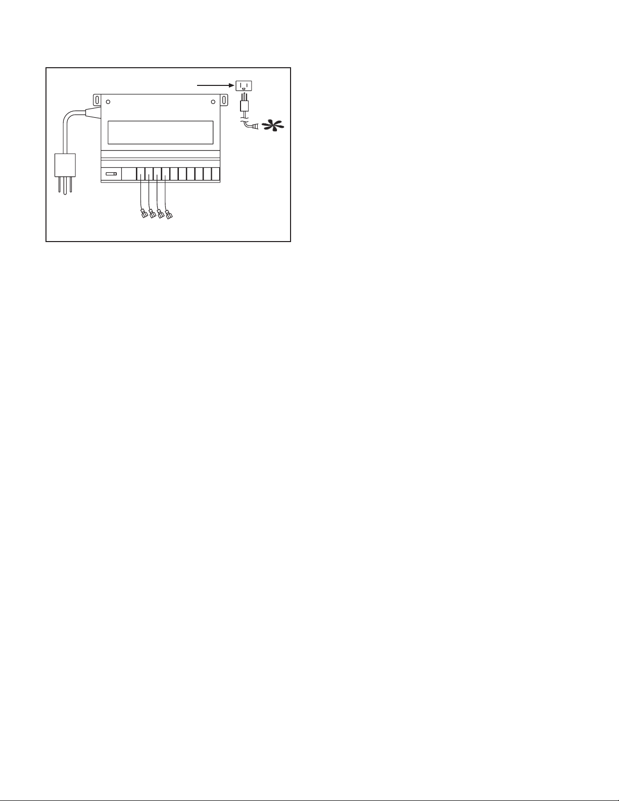
The remote receiver has a 3-position slide switch: OFF/
REMOTE/ON (see Figure 6).
(Receptacle on back)
LEARN
REMOTE
RECEIVER
Figure 6. Remote Receiver
110/120 VAC, 3A
Line cord
from fan
NOTE: The remote receiver will only respond to the
transmitter when the 3-position slide button on the
remote receiver is in the Remote position. If the
system does not respond to the transmitter on initial
use, see section Matching Security Codes.
1. With the slide switch in the ON position, the system
is on.
2. With the slide switch in the REMOTE position, the
system only operates if the remote receiver receives
commands from the transmitter.
3. With the slide switch in the OFF position, the system
is off.
NOTE: The slide switch should be placed in the OFF position if you will be away from your home for an extended
period of time. Placing the switch in the OFF position also
functions as a safety “lock out” by turning the system off
and rendering the remote receiver inoperative.
TRANSMITTER
Important: Before operating remote control, transmitter and receiver must have matching security codes.
See section ‘Matching Security Codes’.
Important: Review ‘Thermo-Updating/Communication-
Safety Features’ under ‘Transmitter Safety Features’
section. Communication Safety features shut down the
fi replace system when a potentially unsafe condition
exists.
Important: Review ‘Auto Shutdown’ section. This safety
feature shuts down the fi replace after 9 hours of continu-
ous operation, in ON mode only.
Important: New or fully charged batteries are essential
for proper operation of the multi-function transmitter. The
transmitter operates on 2 AAA-size 1.5V batteries. Use
Alkaline batteries for longer battery life and maximum
operational performance.
Insert 2 AAA-size 1.5V batteries into the battery compartment on the back of the transmitter. When the batteries
are correctly inserted, the screen will display numbers
(see Figure 7 for LCD Display Screen).
NOTE: If the transmitter is activated from a very cold
condition it may be necessary to allow the transmitter to
stabilize to room temperature (could take up to 15 minutes) before accurate room temperatures are displayed
on the screen.
NOTE: LCD screen is equipped with a “backlite” for
easier viewing of LCD screen. Backlite illuminates when
a function button is depressed. After 5 seconds elapses,
LCD screen will return to its normal state.
4
Page 5

1. LOW - Battery power low. Replace batteries within two weeks.
2. TIMER - Indicates time remaining before system shuts off, when timer-programmed, 9
- hour maximum setting.
3. MODE - Indicates operation MODE of system. ON indicates the system is on, either
manually or thermostatically. THERMO indicates the system will automatically cycle
ON/OFF , depending on programmed SET temperature. OFF indicates the entire system
is turned off.
4. SET - Indicates desired SET room temperature for THERMO operation.
5. FLAME - Single or double Flame/Hi icon indicates
burner/valve operational.
6. CLOCK - Indicates the current time in AM/PM.
7. ROOM - Indicates CURRENT room temperature.
8. ºF - Indicates degrees Fahrenheit (ºC indicates degrees
Celsius).
9. FAN - Indicates fan is on or programmed to come on.
Three speed settings are available.
Figure 7. Transmitter LCD Display Screen
MATCHING SECURITY CODES
It may be necessary to program the remote receiver to
the security code of the transmitter upon initial use, if
batteries are replaced, or if a replacement transmitter
is purchased from your dealer. To program the remote
receiver:
1. Set the slide button on the receiver to the REMOTE
position.
2. Push the LEARN button (one beep will be heard) on
the top of the remote receiver.
3. Then press the MODE button on the transmitter.
Several beeps indicate the transmitter’s code has
been programmed into the receiver. When an existing receiver is matched to a new transmitter, the new
security code will overwrite the old one. NOTE: When
the LEARN button is depressed, “beeping” sounds
should be heard. If no “beeping” is heard check to
see that the receiver has 110-120VAC power to it.
If you are unsuccessful in matching the security code on
the fi rst attempt, wait 1-2 minutes before trying again.
OPERATING INSTRUCTIONS
To operate the system, press the MODE button (Figure
7) on the transmitter to select the operational MODE
desired.
• ON indicates the system is on, either manually, timed
or thermostatically.
• THERMO indicates the system will automatically cycle
ON/OFF, depending on programmed set temperature.
• OFF indicates the entire system is turned off.
LCDDISPLA YSCREEN
THERMO
3
7
ROOM
6
ON
OFF
F
F
SET
AM
TIMER
1
4
8
2
MODE
SET
TIMER
TIME
FAN
5
FLAME
Transmitter Settings
Flip open the plastic cover on the front of the transmitter
to expose the “SET” buttons.
NOTE: Flashing numbers on the display indicate the
system is waiting for input, such as using the UP and
DOWN buttons to program a new setting. If no change
is made to fl ashing digits within 15 seconds, the system
will complete the procedure last programmed and reset
the display to its normal state.
Setting the Clock
1. Press and hold the TIMER/TIME button on the transmitter for more than two seconds. The hour digit(s)
will begin fl ashing (see Figure 7, Location #6).
2. Press the UP or DOWN button until the desired hour
is displayed in AM or PM.
3. After setting the desired hour, press and release the
TIMER/TIME button again to set the minutes; the
minute digits will begin fl ashing.
4. Press the UP or DOWN button until the desired minutes are displayed.
5. Press and hold the TIMER/TIME button again for more
than two seconds. The time digits will cease fl ashing,
indicating the clock has been successfully set. You
may also press the SET button on the transmitter to
stop the time digits from fl ashing and set the time.
5
UP
DOWN
FLAME
Page 6

Figure 8. Setting Button/Child Proof Lockout
Setting ºF/ºC Scale
The factory setting for temperature is degrees Fahrenheit
(ºF). To change this setting to degrees Centigrade (ºC):
1. Remove the battery cover on the back of the transmitter and locate the “setting button” at the top center of
battery compartment (see Figure 8).
2. Push setting button and ºF will begin fl ashing on the
LCD screen (see Figure 7, Location #4).
3. Push the DOWN button on the transmitter to change
ºF to ºC.
4. Push “setting button” on transmitter and Centigrade
(ºC) degree readings will display on LCD screen.
5. Repeat this process to change back to Fahrenheit (ºF)
reading, this time pushing the UP button. NOTE: LCD
screen will return to normal state if setting button is
not pushed within 15 seconds.
Setting Desired Room Temperature Thermo Operations
This remote control system can be thermostatically
controlled when the transmitter is in the THERMO
mode. (THERMO must be displayed on the screen). The
transmitter will “sense” the room temperature every two
minutes automatically turning the fi replace ON or OFF
thermostatically. To set the desired room temperature:
1. Press the MODE button to place the transmitter into
THERMO mode. THERMO ON or OFF will display.
2. Press the UP or DOWN button to select the desired room
temperature. The highest SET temperature is 99º F (32º
C). The lowest SET temperature is 45º F (6º C).
NOTE: To prevent repeated thermo-cycling of the gas
appliance, the sensing unit in the transmitter will only activate the remote receiver when the temperature change
exceeds 2º F (1º C) above or below the SET (desired)
temperature.
When the transmitter is in the THERMO mode, it should
be kept away from direct sources of heat such as fi re-
places, incandescent lighting and direct sunlight. Leaving
the transmitter in direct sunlight, for example, will cause it
to read the room temperature higher than it actually is.
Setting the Countdown Timer
This remote control system can operate with a built-in
countdown timer when the transmitter is in the ON or
THERMO modes (THERMO or ON must be displayed
on the LCD screen).
1. Press and release the TIMER/TIME button on the
transmitter. The word TIMER and 0:15 fl ash on the
screen (see Figure 7, Location #2).
2. Press the UP and DOWN button to begin advancing
through each of the countdown time options. A vailable
countdown times are 15 min, 30 min, 45 min, 1 hour,
1 hr 30 min, and each additional half hour up to nine
hours.
3. T o set the TIMER, press the SET button on the transmitter. If the system is ON, it will remain on until the
“time” has expired. If the system is in the THERMO
mode, it will cycle on and off as the room temperature
requires until the “time” has expired.
NOTE: When the timer is used in the THERMO mode,
the THERMO operation will discontinue when the “time”
has expired.
Operating the Fan Operates in ON or THERMO mode
This remote control system has the capability of operating
a 110 VAC fan or blower system that may be included
with your gas fi replace. The fan will only operate when
the transmitter is in the ON or THERMO mode. (THERMO
or ON must be displayed on LCD screen).
1. To turn fan ON, press and release the FAN button
on the transmitter (see Figure 7, Location #9). The
fan will operate at HI speed, and fan blade icon will
appear on LCD screen.
2. T o change fan speed to MED, press and release F AN
button again. To change fan speed to LO, press and
release FAN button again.
3. T o turn fan OFF , press and release F AN button again.
Fan blade icon will disappear from LCD screen.
6
Page 7

Adjusting the Flame Height Operates in ON or THERMO mode
This remote control system allows the user to control
the height of the FLAME when the gas valve is factory
equipped with a FLAME CONTROLLER.
1. Press and release FLAME button to change fl ame
height to HI (see Figure 7, Location #5), (a second
fl ame icon appears).
2. Press again to return fl ame to normal state.
Low/Battery Indicator
An “X” outlined by a battery on the right side of the LCD
screen will appear when battery power has dropped
signifi cantly. At this time, approximately two weeks of
battery power remains.
Child Proof Lockout (CP)
The transmitter contains a “Child Proof” lockout feature
that prevents unauthorized use of the remote control. To
access the “Child Proof” activation button, remove cover
on BACK of transmitter. To activate LOCKOUT:
1. Press and hold in the “setting button” for 5 seconds.
The letters CP will display on the LCD screen (see
Figure 8). This prevents the activation of fi replace.
When any function button is pressed ON/OFF etc.
the letter CP will display on the LCD screen.
To deactivate LOCKOUT:
1. Press and hold in the “setting button” for 5 seconds. The
LCD will display CP until 5 seconds have elapsed, and
then the LCD screen will return to its normal state.
TRANSMITTER SAFETY FEATURES
It is recommended that the TRANSMITTERS always be
located within a 20 foot operating range of the fi replace,
preferably in the same room in which the fi replace system
is located. The TRANSMITTER features several safety
features that alert the user when the TRANSMITTER is
placed outside the 20 foot normal operating range.
Thermo-Updating and Communication-Safety Features
This remote control has a COMMUNICATION-SAFETY
function built into its software. It provides an extra margin
of safety when the TRANSMITTER is out of the normal
20 foot operating range of the receiver. It is also activated
when the batteries become weak or are removed from
the transmitter.
In the THERMO-UPDATING feature (only in the THERMO or TIMER modes) the transmitter normally reads
the ROOM temperature every 2 minutes. In addition to
checking the temperature, the transmitter sends a signal
to the receiver indicating that the transmitter and its batteries are still active.
In the COMMUNICATION-SAFETY feature, at all times
and in all OPERATING MODES the transmitter sends a
signal every fi fteen (15) minutes to the receiver, indicat-
ing that the transmitter is within the normal operating
range of 20 feet.
Should the receiver NOT receive a transmitter signal
every 15 minutes (COMMUNICATION-SAFETY feature), the RECEIVER will begin a 2 HOUR (120 minute)
countdown timing function. If during this 2 hour period,
the receiver does not receive a signal from the transmitter, the RECEIVER will shut down the fi replace being
controlled by the receiver. The RECEIVER will then emit
a series of rapid “beeps”. Then, after 10 rapid “beeps”,
the RECEIVER will continue to emit a single “beep” every
4 seconds until a transmitter signal is again received.
The intermittent 4 second beeping will go on indefi nitely
until reset.
To “reset” the RECEIVER and operate the fi replace
system:
1. Press the MODE button on the transmitter. The word
ON must display on the LCD screen. The COMMUNICATION -SAFETY operation is overridden and the
system will return to normal operation depending on
the MODE selected at the transmitter.
We recommend the user check the batteries in the
TRANSMITTER to make sure the voltage is no less
than 2.7 volts.
Auto Shutdown
This remote control has an Auto Shutdown feature incorporated into its system. When the transmitter MODE is
in the ON position the fi replace will continuously operate
for 9 hours. After 9 hours, the fi replace will shut down.
To relight the fi replace:
1. Press the MODE button. The fi replace will operate
continuously for up to 9 hours before Auto Shutdown
repeats cycle. The Auto Shutdown signal comes from
the transmitter. The transmitter must be positioned
within a 20 foot operating range for the Auto Shutdown
feature to operate.
SYSTEM CHECK
Millivolt Valves
Light the appliance following the lighting instructions
that came with the fi replace. Confi rm that the pilot fl ame
is on. It must be in operation for the main gas valve to
operate.
1. Slide the 3-position button on the remote receiver to
the ON position. The main gas fl ame (i.e., the fi re)
should ignite.
2. Slide the button to OFF. The fl ame should extinguish
(the pilot fl ame will remain on).
3. Slide the button to REMOTE (the center position),
then press the MODE button on the transmitter to
change the system to ON. The main gas fl ame should
ignite.
4. Press the MODE button on the transmitter to change
the system to OFF. The fl ame should extinguish (the
pilot fl ame will remain on).
5. Press the MODE button on the transmitter to change
the system to THERMO.
7
Page 8

6. Advance the SET temperature on the transmitter to a
temperature of at least 2º F (1º C) above the ROOM
temperature displayed on the LCD screen and the
system fl ame will ignite.
7. Set the SET temperature to at least 2º F (1º C) below
the room temperature and the system fl ame will extin-
guish. Thereafter, it should continue to cycle on and
off thermostatically approximately every two minutes
as the ROOM temperature changes, but only when
the temperature differential between ROOM and SET
temperatures differs at least 2º F (1º C). The 2º F differential is the factory setting.
Electronic Ignition System
1. Slide the 3-position button on the remote receiver to
the ON position. The spark electrode should begin
sparking to ignite the pilot (the pilot may ignite after
only one spark). After the pilot fl ame is lit, the main
gas valve should open and the main gas fl ame should
ignite.
2. Slide the button to OFF. The main gas fl ame and pilot
fl ame should BOTH extinguish.
3. Slide the button to REMOTE (the center position).
4. Then press the MODE button on the transmitter to
change the system to ON. The spark electrode should
begin sparking to ignite the pilot. After the pilot is lit,
the main gas valve should open and the main gas
fl ame should ignite.
5. Press the MODE button on the transmitter to OFF.
The main gas fl ame and pilot fl ame should BOTH
extinguish.
6. Press the MODE button on the transmitter to change
the system to THERMO.
7. Advance the SET temperature on the transmitter to
temperature of at least 2º F (1º C) above the room
temperature displayed on the LCD screen and the
system fl ame will ignite.
8. Set the SET temperature to at least 2º F (1º C) below
the room temperature and the system will extinguish.
Thereafter, it should continue to cycle on and off
thermostatically approximately every two minutes as
the ROOM temperature changes, but only when the
temperature differential between ROOM and SET
temperatures differ at least 2º F (1º C). The 2º F differential is the factory setting.
Timer Operation
The countdown timer will operate in either the manual ON
or THERMO mode. Once the fi replace system is in an
operating mode, set the countdown timer to turn off in 15
minutes. The timer function will allow operation to continue
until the “countdown time” on the LCD screen expires. After
15 min. elapses, the system should turn off.
GENERAL INFORMATION
Transmitter Wall Bracket
The transmitter can be hung on a wall using the bracket
provided. Locate the bracket on an inside wall suffi -
ciently far away from direct sources of heat such as a
fi replace, incandescent lighting, or sunlight so it detects
ambient room temperatures, not a single heat source.
If the bracket is installed on a solid wood wall, drill 1/8”
pilot holes and install with the screws provided. If it is
installed on a plaster/wallboard wall, fi rst drill two 1/4”
holes into the wall, then use a hammer to tap in the two
plastic wall anchors fl ush with the wall, then install the
screws provided.
Battery Life
Life expectancy of the batteries in the transmitter should
be at least 12 months. Check batteries annually . When the
transmitter no longer operates the remote receiver from
a distance it did previously (i.e., the transmitter’s range
has decreased) the batteries should be checked.
Specifi cations
Batteries: Transmitter - 3V 2 ea.; AAA 1.5V, Alkaline
Remote - 110-120 VAC; 60Hz
Operating Frequency: 303.8 MHZ
FCC ID No.’s: Transmitter - K9L300ITX
Receiver - K9L3003RX
Canadian ISC ID No.’s: Transmitter - 2439 102 760
Receiver - 2439 102 760A
Service Parts List
DESCRIPTION SERVICE PART NO.
3-PRONG ADAPTER HTI-18-006
SOLENOID-110 VOLT HI/LO HTI-17-006
TRANSMITTER WALL HOLDER HTI-16-006
BATTERIES-TRANSMITTER HTI-14-006
RECEIVER HTI-13-006
TRANSMITTER (RCT-MLT-HNG) HTI-12-006-HNG
TRANSMITTER (RCT-MLT-HTL) HTI-12-006-HTL
HARDWARE PACKAGE HTI-11-006
Limited Warranty
This REMOTE CONTROL SYSTEM is warranted for 12
months from the date of purchase or installation to the
original purchaser to be free from defects in materials
and workmanship. Damage to the SYSTEM caused by
accident, misuse, abuse, or installation error whether
performed by a contractor, service company, or owner, is
not covered by this warranty . Seller will not be responsible
for labor charges and/or damage incurred in installation,
repair, replacement or for incidental or consequential
damages. Batteries and any damage caused by them
are not covered by this warranty.
Some states, provinces, and nations do not allow exclusion or limitations of incidental or consequential damages,
so the above limitations or exclusions may not apply . This
warranty gives you specifi c legal rights. You may have
other rights that vary by state, province or nation.
8
Page 9

IGNITION MODULE 3 VAC INTERMITTENT PILOT IGNITOR
I
S
BATTERY PACK
THERMOSTAT
WIREASSEMBLY
TRANSFORMER
3VAC
HOT
NEUTRAL
PLUG IN
D
E
R
JUMPER WIRE
(TO BROWN)
WHITE
ORANGE
GROUND TO
FIREPLACE
CHASSIS
ORANGE
VALVE
GREEN
Figure 9. Intermittent Pilot Ignition (IPI) Wiring Diagram
PIEZO
PILOT
THERMOCOUPLE
WHITE
VALVE
RED
Figure 10. Standing Pilot Ignition Wiring Diagram
THERMOSTAT
WIRE ASSEMBLY
9
Page 10

3V TRANSFORMER
V
ON/OFF
WALL
SWITCH
VALVE
NEUTRAL
PLUG-IN
IGNITION
MODULE
(3V)
LOW VOLTAGE
GROUND
FLAME SPARKER/
SENSOR
SEE NOTE 1
REMOTE
CONTROL
HOT
IGNITION MODULE
3VAC
I
S
WHT
ORG
GROUNDTO
FIREPLACE
CHASSIS
INTERMITTENT
PILOT
IGNITOR
WHITE WIRE
CAN BE
PLUGGED
INTOANY
BLACK WIRE CAN BE
PLUGGED INTO ANY OF
#1 - #5 LOCATIONS
ON THE HOT SIDE
OF #1-#5
LOCATIONS
ON THE
NEUTRAL SIDE
TRANSFORMER
PLUG IN
Figure 11. Intermittent Pilot Ignition (IPI) Wiring Diagram
3/16” PIGGYBACK CONNECTOR
3VAC
BLACK S2
BRN
PIGGYBACK
ON/OFF SWITCH
BRN
ORG
GRN
ALVE
REMOTE SWITCH
PIGTAIL
ON
OFF
ON/OFF
SWITCH
OPTIONALWALL SWITCH,
THERMOSTAT OR REMOTE
THERMOCOUPLE
GAS VALUE
WHITE T2
RED T1
THERMOPILE
BLACK S1
Figure 12. Standing Pilot Ignition Wiring Diagram
10
Page 11

Remote Control Wiring Diagrams
V
BATTERY PACK
REMOTE RECEIVER
TRANSFORMER
3 VAC
PLUG IN
IGNITION MODULE 3 VAC
K
C
A
L
B
D
E
R
JUMPER WIRE
(TO BROWN)
INTERMITTENT PILOT IGNITOR
I
S
WHITE
ORANGE
GROUND TO
FIREPLACE
CHASSIS
ORANGE
GREEN
Figure 13. Remote Control Intermittent Pilot Ignition (IPI) Wiring Diagram
PILOT
THERMOCOUPLE
VALVE
WHITE
RED
ALVE
PIEZO
REMOTE RECEIVER
Figure 14. Remote Control Standing Pilot Ignition Wiring Diagram
11
 Loading...